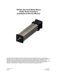
1
I-Series Universal Motor Mount Roller Screw Actuators Installation & Service Manual Information furnished by Curtiss-Wright, Exlar Actuation Group, is believed to be accurate and reliable. However, no responsibility is assumed by Curtiss-Wright for its use. Curtiss-Wright reserves the right to change the design and operation of the equipment described herein and any associated motion products that may appear in this document. Information in this document pertaining to equipment not furnished by Curtiss-Wright should be confirmed by that equipment manufacturer. Curtiss-Wright assumes no responsibility for changes to information by other manufacturers or errors in that information or the description of that information. Information in this document is subject to change without notice. I Series Manual.doc PN: 27667 Rev. Q 11/25/2014 Curtiss-Wright 952-500-6200 Table of Contents 1.0 Introduction 1.1 Warranty and Limitations of Liability . . . . . . . . . . . . . . . . . . . . . . . . . . 1.2 Safety Considerations . . . . . . . . . . . . . . . . . . . . . . . . . . . . . . . . . . . . . 1.3 I Series Roller Screw Based Linear Actuators Overview . . . . . . . . . . . 1.4 Basic Actuator Construction . . . . . . . . . . . . . . . . . . . . . . . . . . . . . . . . 1.5 Actuator Drive Train Configurations . . . . . . . . . . . . . . . . . . . . . . . . . . 3 4 5 5 6 2.0 Installation 2.1 Mounting Configurations . . . . . . . . . . . . . . . . . . . . . . . . . . . . . . . . . . . 2.2 Mounting Considerations . . . . . . . . . . . . . . . . . . . . . . . . . . . . . . . . . . 2.3 Lubrication . . . . . . . . . . . . . . . . . . . . . . . . . . . . . . . . . . . . . . . . . . . . . 2.4 Anti-Rotate System . . . . . . . . . . . . . . . . . . . . . . . . . . . . . . . . . . . . . . 9 9 12 12 3.0 Maintenance & Service 3.1 Seals . . . . . . . . . . . . . . . . . . . . . . . . . . . . . . . . . . . . . . . . . . . . . . . . 3.2 Thrust Bearings . . . . . . . . . . . . . . . . . . . . . . . . . . . . . . . . . . . . . . . . . 3.3 Drive Train . . . . . . . . . . . . . . . . . . . . . . . . . . . . . . . . . . . . . . . . . . . . . 3.4 Roller Screw . . . . . . . . . . . . . . . . . . . . . . . . . . . . . . . . . . . . . . . . . . . 3.5 End of Stroke Cushions . . . . . . . . . . . . . . . . . . . . . . . . . . . . . . . . . . . 3.6 Inspection and Lubrication Procedure . . . . . . . . . . . . . . . . . . . . . . . . 3.7 Fastener Torque Values . . . . . . . . . . . . . . . . . . . . . . . . . . . . . . . . . . . 3.8 Pulley Set Screw Torque Values. . . . . . . . . . . . . . . . . . . . . . . . . . . . . 14 15 15 19 19 21 28 29 4.0 Optional Equipment 4.1 Mounting Options . . . . . . . . . . . . . . . . . . . . . . . . . . . . . . . . . . . . . . . 4.2 Standard Motor Mounting Configurations . . . . . . . . . . . . . . . . . . . . . 4.3 Limit Switches . . . . . . . . . . . . . . . . . . . . . . . . . . . . . . . . . . . . . . . . . . 4.4 Rod Ends. . . . . . . . . . . . . . . . . . . . . . . . . . . . . . . . . . . . . . . . . . . . . . 4.5 Motors . . . . . . . . . . . . . . . . . . . . . . . . . . . . . . . . . . . . . . . . . . . . . . . . 4.6 Electronics . . . . . . . . . . . . . . . . . . . . . . . . . . . . . . . . . . . . . . . . . . . . . 30 30 30 30 31 31 5.0 Specifications 5.1 Travel Life Calculations . . . . . . . . . . . . . . . . . . . . . . . . . . . . . . . . . . . 32 5.2 Load, Torque, and Linear Speed Calculations . . . . . . . . . . . . . . . . . . 32 5.3 Load and Speed Ratings . . . . . . . . . . . . . . . . . . . . . . . . . . . . . . . . . . 34 6.0 Troubleshooting 6.1 Mechanical Problems . . . . . . . . . . . . . . . . . . . . . . . . . . . . . . . . . . . . . 36 6.2 Electrical Problems . . . . . . . . . . . . . . . . . . . . . . . . . . . . . . . . . . . . . . 36 6.3 Returning a Product for Repair . . . . . . . . . . . . . . . . . . . . . . . . . . . . . . 36 I Series Manual. PN: 27667 Rev.Q Page 2 11/12/14 Curtiss-Wright 952-500-6200 1.0 Introduction 1.1 Warranty and Limitations of Liability Products are warranted for two years from date of manufacture as determined by the serial number on the product label. Labels are generated and applied to the product at the time of shipment. The first and second digits are the year and the third and fourth digits represent the manufacturing week. Product repairs are warranted for 90 days from the date of the repair. The date of repair is recorded within Exlar’s database tracked by individual product serial number. Exlar warrants its product(s) to the original purchaser and in the case of original equipment manufacturers, to their original customer to be free from defects in material and workmanship and to be made only in accordance with Exlar's standard published catalog specifications for the product(s) as published at the time of purchase. Warranty or performance to any other specifications is not covered by this warranty unless otherwise agreed to in writing by Exlar and documented as part of any and all contracts, including but not limited to purchase orders, sales orders, order confirmations, purchase contracts and purchase agreements. In no event shall Exlar be liable or have any responsibility under such warranty if the product(s) has been improperly stored, installed, used or maintained, or if Buyer has permitted any unauthorized modifications, adjustments and/or repairs to such product(s). Seller's obligation hereunder is limited solely to repairing or replacing (at its opinion), at the factory any product(s), or parts thereof, which prove to Seller's satisfaction to be defective as a result of defective materials, or workmanship and within the period of time, in accordance with the Seller's stated product warranty (see Terms and Conditions above), provided, however, that written notice of claimed defects shall have been given to Exlar within thirty (30) days from the date of any such defect is first discovered. The product(s) claimed to be defective must be returned to Exlar, transportation prepaid by Buyer, with written specification of the claimed defect. Evidence acceptable to Exlar must be furnished that the claimed defects were not caused by misuse, abuse, or neglect by anyone other than Exlar. Components such as seals, wipers, bearings, brakes, bushings, gears, splines, and roller screw parts are considered wear parts and must be inspected and serviced on a regular basis. Any damage caused by failure to properly lubricate Exlar products and/or to replace wear parts at appropriate times, is not covered by this warranty. Any damage due to excessive loading is not covered by this warranty. The use of products or components under load such that they reach the end of their expected life is a normal characteristic of the application of mechanical products. Reaching the end of a product’s expected life does not indicate any defect in material or workmanship and is not covered by this warranty. Costs for shipment of units returned to the factory for warranty repairs are the responsibility of the owner of the product. Exlar will return ship all warranty repairs or replacements via UPS Ground at no cost to the customer. For international customers, Exlar will return ship warranty repairs or replacements via UPS Expedited Service and cover the associated shipping costs. Any VAT or local country taxes are the responsibility of the owner of the product. The foregoing warranty is in lieu of all other warranties (except as Title), whether expressed or implied, including without limitation, any warranty of merchantability, or of fitness for any particular purpose, other than as expressly set forth and to the extent specified herein, and is in lieu of all other obligations or liabilities on the part of Exlar. Seller's maximum liability with respect to these terms and conditions and any resulting sale, arising from any cause whatsoever, including without limitation, breach of contract or negligence, shall not exceed the price specified herein of the product(s) giving rise to the claim, and in no event shall Exlar be liable under this warranty otherwise for special, incidental or consequential damages, whether similar or dissimilar, of any nature arising or resulting from the purchase, installation, removal, repair, operation, use or breakdown of the product(s) or any other cause whatsoever, including negligence. The foregoing warranty shall also apply to products or parts which have been repaired or replaced pursuant to such warranty, and within the period of time, in accordance with Seller's stated warranty. NO PERSON INCLUDING ANY AGENT OR REPRESENTATIVE OF EXLAR IS AUTHORIZED TO MAKE ANY REPRESENTATION OR WARRANTY ON BEHALF OF EXLAR CONCERNING ANY PRODUCTS MANUFACTURED BY EXLAR, EXCEPT TO REFER PURCHASERS TO THIS WARRANTY. I Series Manual. PN: 27667 Rev.Q Page 3 11/12/14 Curtiss-Wright 952-500-6200 1.2 Safety Considerations As with any electro-mechanical device, safety should be considered during installation and operation of your I Series actuator. Throughout this manual you will see paragraphs marked with WARNING or CAUTION signs as shown below. CAUTION WARNING Pay particular attention to these paragraphs. They are intended to provide you with helpful information to ensure a safe and trouble free installation and operation. Care should be taken not to exceed the physical travel limits of I Series actuators. Doing so will cause the actuator to impact its end of travel bumpers. Repeated end of travel crashes can physically damage the roller screw and the internal components of the actuator. Care should be taken to avoid high speed impact with objects of high rigidity that immediately stop the travel of the actuator with no deceleration or energy absorption. An example would be a high speed impact of two solid steel parts. The resulting impact will create a very short effective deceleration time. Kinetic energy contained in the rotating inertia of the actuator and motor can possibly generate extremely high impact forces that exceed the mechanical capacities of the actuator and cause physical damage to the actuator. For applications requiring this type of impact, contact Exlar application engineering to insure that the actuator is properly sized or provisions are made to absorb the induced energy. I Series Manual. PN: 27667 Rev.Q Page 4 11/12/14 Curtiss-Wright 952-500-6200 1.3 I Series Linear Actuators Overview Exlar I Series actuators are offered in three standard nominal frame sizes of 2, 3 and 4 inches. Continuous duty thrust load ratings for the I Series product range from 145 lbf to 3966 lbf. (644-17642 N) Intermittent load ratings for each actuator are twice the respective continuous duty load rating. Exlar I Series actuators utilize a planetary roller screw mechanism to converts rotary to linear motion. The planetary roller screw offers superior travel life, rigidity, and resistance to shock load than the ball screws commonly found in electromechanical actuators. The planetary roller screw is mounted within a sealed, extending tube package. The main rod extends or retracts as the input drive shaft is rotated. The general operating principle is illustrated below. CCW Shaft rotation looking at input shaft of base unit = Extending motion CW Shaft rotation looking at input shaft of base unit = Retracting motion The I Series actuator designs offer contamination protection to IP54 or IP65 levels depending on the specific series or options selected. All rotary to linear conversion components are mounted within an IP65 or IP54 sealed housing. These levels of sealing protect the actuators internal components from particulate contamination or from corrosive agents. 1.4 Basic Actuator Construction The IP65 I Series designs offer o-ring seals at each housing joint, and a rod wiper to seal out liquid and particulate contaminates. Table of rod wiper manufacturer and PN can be found on page 27. The IP54 I Series designs offer protection from particulate contaminates, but are not sealed against liquid penetration. The aluminum actuator case and housing parts are anodized. All steel mounting parts (flange mounts, side lug plates, trunnions, etc.) offer a black oxide finish. Corrosion resistant options offer these mounting parts in stainless steel or with QPQ corrosion resistance heat treatment. Electroless Nickel and hard coat anodizing are available corrosion resistant options for the actuator housing and case parts. These finishes are intended to retard corrosion. The specific environment of the customer’s application should be discussed with Exlar application engineers. I Series Manual. PN: 27667 Rev.Q Page 5 11/12/14 Curtiss-Wright 952-500-6200 If the environment in which the I Series actuator will be commissioned involves contact with corrosive substances, contact Exlar for application assistance. The standard I Series output rod is manufactured from 4100 Series steel and is heat treated with a corrosion resistance QPQ process that provides corrosion resistance and wear resistance. If the extending rod of the I Series actuator is subject to abrasions, scratches and dents, this will allow contaminants to be carried past the actuators or wiper and will cause the wiper to wear prematurely allowing contamination to the internal components of the actuator. 1.5 Actuator Configurations The I Series base unit actuator includes a high performance planetary roller screw assembly, bearing support, anodized extruded aluminum housing, precision internal anti-rotate sliders, extending rod, and an input shaft for attachment to your drive system. An I Series base unit is shown below. Input Shaft Figure 2: I Series Base Model Actuator I Series Manual. PN: 27667 Rev.Q Page 6 11/12/14 Curtiss-Wright 952-500-6200 The I Series actuators are also available with provisions for mounting various motors. Standard motor mountings include parallel with belt drive, inline direct drive, and inline with planetary gearing. The parallel motor mounting configuration utilizes a high performance belt drive system, which while providing quiet operation, requires no re-tensioning for the life of the actuator as long as the motor is not removed or adjusted. Drive speed reduction ratios between 1:1 and 2:1 are available, with 1:1 and 2:1 being standard. Speed increasing ratios are available also. Figure 3: I Series with Parallel Motor Mount I Series Manual. PN: 27667 Rev.Q Page 7 11/12/14 Curtiss-Wright 952-500-6200 The inline motor mounting configuration uses a zero backlash coupling attaching the motors output shaft to the actuators drive shaft. Figure 4: I Series with Inline Motor Mount The inline planetary gearing option offers 5:1 or 10:1 planetary gear reduction. The planetary gearing is integral to the input of the actuator and an inline coupling is included to attach the motor’s output shaft to the input of the planetary gear stage. Figure 5: I Series with Inline Gearset Motor Mount I Series Manual. PN: 27667 Rev.Q Page 8 11/12/14 Curtiss-Wright 952-500-6200 2.0 Installation 2.1 Mounting Configurations The I Series actuators offer a wide variety of mounting accessories. The standard mounting accessories are; side lug or foot mounts, side mounted flange attachments and side mounted trunnions. Each of these mounting components utilizes the T-Slot tracks on the sides of the case for attachment. Also available is a front flange mount that is integral to the actuator housing and does not attach via the T slots. 2.2 Mounting Considerations Care should be taken to mount the I Series actuator such that its linear travel is well aligned with the allowable travel of its load. Misalignment imparts direct side load on the actuator’s extending rod. Side loading of the actuators extending rod leads to accelerated seal wear, bearing wear and roller screw wear, and should be avoided. Excessive side load on the output rod of the actuator may reduce the travel and seal life of the actuator. T Slot mounting hardware should be attached perpendicular to the axis of linear motion. All T-Nuts and associated flathead cap screws should be tightened to the appropriate torque level indicated in section 3.7 Fastener Torque Values. I Series Manual. PN: 27667 Rev.Q Page 9 11/12/14 Curtiss-Wright 952-500-6200 Mounting hardware installation: Step 1: Remove faceplate screws Step 2: Remove faceplate and rod wiper. If O-Ring does not stay in place, remove that as well (IP65 units only) Step 3: You may preassemble the T-nuts, with mounting attachments and appropriate Flat Head Cap Screws to be held loosely together as you guide the T-nuts into the slots. Alternatively, you can slip the T-Nuts into the slots, and then assemble the mounting components and screws to the captive T-Nuts. Once the components are fully engaged in the T-nuts, it is advised that you lightly tighten one screw on each mounting component to prevent it from sliding back and forth as you reassemble the actuator. I Series Manual. PN: 27667 Rev.Q Page 10 11/12/14 Curtiss-Wright 952-500-6200 I Series Mounting Hardware Torque Specifications Actuator IM/X20 Component Mounting Component T Nut/bolt, Black Oxide Mounting Component T Nut/bolt, Stainless IM/X20 Steel IM/X30 Mounting Component T Nut/bolt, Black Oxide Mounting Component T Nut/bolt, Stainless IM/X30 Steel IM/X40 Mounting Component T Nut/bolt, Black Oxide Mounting Component T Nut/bolt, Stainless IM/X40 Steel All values are assuming dry (not oily or plated components) in-lbs 252 ft-lb 21 N-m 28.5 169 252 14 21 19.1 28.5 169 252 14 21 19.1 28.5 169 14 19.1 Step 4: Rotate the drive shaft to extend the main rod about 2” from the fully retracted position. If the ORing has been removed, place O-Ring grease in the groove and fit the O-Ring back into the groove. Slide the wiper onto the main rod, leaving enough space for your fingers between the wiper and the front of the case. The flange on the wiper points towards the rod end as shown. Put the face Plate over the rod (with the counter bore for the wiper facing the wiper) and with your fingers press the wiper into the faceplate counter bore, while keeping it on the main rod cylinder. Then press the faceplate down onto the O-Ring and rotate it so the holes line up. I Series Manual. PN: 27667 Rev.Q Page 11 11/12/14 Curtiss-Wright 952-500-6200 Step 5: Torque faceplate screws to recommended value (see Section 3.4) Position mounting hardware to the same distance from the face plate and torque Flathead Cap Screws to their recommended value. 2.3 Lubrication Exlar’s I Series actuators are shipped from the factory fully lubricated with high temperature grease. Periodic inspection and renewal of the bearing and roller screw grease is recommended according to the periods shown in the table below. Follow the procedure in section 3.6 for renewing grease. RMS Rotational Speed (rpm) Recommended Grease Renewal Period (hours) 250 10,000 500 10,000 1000 8000 1500 7000 2000 5800 2500 5000 3000 4000 For duty cycles of varying speeds use RMS rotational speed to determine grease renewal period. To determine this value follow the equation below: Vrms = [(V12t1+ V22t2+V32t3+…)/ (t1+t2+t3+…)] 1/2 Where: Vrms = RMS Rotational speed (rpm) V1,2,3… = Rotational speed of roller screw shaft for corresponding t1,2,3… time (rpm) t1,2,3… = Time at corresponding V1,2,3… rotational speed (minutes) Over greasing or cold grease may cause elevated motor torque. Exlar recommends using Mobilith SHC 220, a high performance, extreme-pressure grease. The unique physical properties of the synthetic base oil provide outstanding protection against wear, rust, corrosion and high or low-temperature degradation. Mobilith SHC allows for very low starting and running torque values. Its operating range is -40 degrees C to 177 degrees C (-40 degrees F to 350 degrees F). For lubrication of seals see section 3.1. For inspection and lubrication procedure see section 3.6. 2.4 Anti-Rotate Mechanism Exlar’s I Series actuators have an internal anti-rotate mechanism. Internal anti-rotation sliders travel in channels integral to the actuator case. The anti-rotate mechanism limits angular motion to 0.35 degrees rotation and is designed to withstand the maximum rated input torque for each respective actuator size. Care should be taken when applying torque to the actuators main rod during rod end or load attachment to not damage the anti-rotate mechanism. The I Series standard main rod designs offer wrench flats that I Series Manual. PN: 27667 Rev.Q Page 12 11/12/14 Curtiss-Wright 952-500-6200 should be used to resist the torque applied when attaching rod end accessories or load attachments. The anti-rotate mechanism should not be used to resist this assembly torque. The anti-rotate mechanism is also the housing for the magnet sensed by the optional limit switches. (See Part Numbers in table below) Figure 6: Anti-Rotate Mechanism I 20 49198 Anti-Rotate Kit, includes magnets and bearings I 30 49199 Anti-Rotate Kit, includes magnets and bearings I 40 49200 Anti-Rotate Kit, includes magnets and bearings To avoid damage to the anti-rotate mechanism, care should be taken during assembly to avoid applying more torque to the main rod than shown below. I 20----5 FT*LBF (6.8Nm) I 30----10 FT*LBF (13.6 Nm) I 40----25 FT*LBF (33.9 Nm) I Series Manual. PN: 27667 Rev.Q Page 13 11/12/14 Curtiss-Wright 952-500-6200 3.0 Maintenance & Service 3.1 Seals I Series actuators provided with IP65 sealing have Buna-n o-rings at the joints of the actuator housing components. The extending rod is sealed with a wiper seal. The input shaft of an IP65 unit is sealed using a spring loaded nitrile shaft seal that is contained within the back end plate of the actuator. These seals are lubricated on initial assembly with a Teflon seal lubricant. The front wiper should have a small amount of mineral oil applied to it periodically depending on amount of actuator use or storage to keep the wiper operating smoothly and to prolong life. The o-rings are treated with an o-ring lubricant designed to slightly swell the o-ring to assure proper sealing. IP65 versions of the inline motor mount and inline gear set actuators have additional o-rings (or gaskets on I 40) between the actuator base unit and the motor mounting plate or gear set housing section. In parallel mounted units the pulley housing is not sealed but may be equipped with drain holes. Contact Exlar application engineers for details about custom sealing options. Figure 7-1: IP65 Base Unit Sealing Details Figure 7-2: IP65 Integrated Motor Mount Unit Sealing Details I Series Manual. PN: 27667 Rev.Q Page 14 11/12/14 Curtiss-Wright 952-500-6200 Figure 7-3: IP65 Gear set/Integrated Motor Mount Unit Sealing Details 3.2 Thrust Bearings IM Series actuators offer two deep groove ball bearings. IX series actuators provide two angular contact bearings mounted in duplex arrangement. These bearings support the drive shaft within the I Series actuator. The inner races of the angular contact bearings are pre-loaded using a bearing jam nut and lock washer to ensure that the pre-loaded condition is not lost. The outer races are pre-loaded by the end plate screws as shown in figure 8. Figure 8: Roller Screw Support Bearing Detail 3.3 Drive Train The parallel motor mount option for the I Series actuators provides a fiberglass reinforced belt and pulley drive train to transmit the motors rotation and torque to the actuators roller screw mechanism. The drive train does not require lubrication. The belt and pulley transmission is housed in a protective housing to help prevent contamination by dirt and debris. The belt housing and cover should be kept in place at all times during operation and should only be removed for motor mounting and drive train inspection. The belt and pulley system should be inspected periodically for wear and proper tensioning. I Series Manual. PN: 27667 Rev.Q Page 15 11/12/14 Curtiss-Wright 952-500-6200 Removing the protective housing from the belt and pulley drive train during operation of the actuator may cause damage to the actuator components or severe injury. Power should be removed and locked out from the actuators motor at any time the the protective drive train cover is removed. Failure to do so can result in damage to the actuator or cause serious injury. Improper belt tension can cause premature belt wear and failure, belt noise and slippage. The following picture is an example of a typical belt and pulley drive train in an I Series actuator. Actual drive trains will vary in configuration depending on exact actuator and motor configuration. Contact Exlar application engineers with any questions regarding the installation or maintenance of the belt and pulley drive train on your I Series Actuator. Figure 9: Parallel Motor Mount Drive Train Assembly I Series Manual. PN: 27667 Rev.Q Page 16 11/12/14 Curtiss-Wright 952-500-6200 Proper Belt Tension Parallel Motor Mounting The motor plate slots allow dropping of the motor so the belt can be placed, followed by raising the motor to tighten the belt. IM/X20 and IM/X30 Belt Tensioning The standard Size 20 and 30 I Series belts are GT2 belts, 5mm pitch, 9mm width. The proper tension for these belts is 1.5 lbs deflection tension for 1/64” deflection per inch of span. The standard center to center distances of the pulleys are: 1:1 Ratio: t = 3.642 inches (92.51 mm) 1:2 or 2:1 Ratio: t = 3.519 inches (89.38 mm) Non-standard configurations may have varying center to center distances. For standard units, the deflection should be: 1:1 Ratio: 1.5 lbs @ 1/16” deflection (0.68 kg @ 1.45 mm) 1:2 or 2:1 ratio: 1.5 lbs @ 1/16” deflection (0.68 kg @ 1.40 mm) IM/X40 Belt Tensioning The I 40 uses a 5mm pitch by 9mm wide belt for lower torque applications and an 8 mm pitch by 22 mm wide belt for higher torque applications. I Series Manual. PN: 27667 Rev.Q Page 17 11/12/14 Curtiss-Wright 952-500-6200 For the 9 mm wide belt, the proper tension is 1.5 pounds force to obtain 1/8 inches of deflection at the center of the belt between the two pulleys. For the 22 mm wide belt, the proper tension is at 4.5 pounds force to get 1/8 inch of deflection at the center of the belt between the two pulleys. These tensioning values apply to all pulley ratios used in the I 40. To identify which belt is used, a 9 mm wide belt = .35 inches wide, or approximately 3/8 of an inch, and a 22 mm wide belt = .866 inches or approximately 7/8 of an inch wide. Inline Motor Mounting (motor adapter or gear set motor adapter) 1.) Remove the clamp access plug by levering under the cap with a flat bladed screwdriver. 2.) Loosen the collar clamp screw so the motor shaft can slide into the shaft adapter/coupler shaft, but maintain enough pressure so the clamp screw stays aligned with the access hole. 3.) Position the splits in the clamp collar, motor coupler, and shaft adapter so they are not lined up with each other. 4.) Place the actuator vertically with the motor mount facing up. Assembling in a vertical orientation will prevent unwanted side load being applied by the motor’s weight. 5.) IP65 UNITS: Place appropriate o-ring around the motor pilot. 6.) Insert the shaft of the motor into the shaft adapter/ motor coupler. Slide the motor down so the motor flange is flush with the motor adapter plate. 7.) Rotate the motor so the mounting holes line up with the holes in the actuator’s motor adapter plate. 8.) Lightly tighten the motor mounting bolts, taking care to maintain alignment without imparting any side loading on the motor shaft. 9.) Tighten motor bolts to the designated torque value. (See table in Section 3.7) 10.) Using a hex key wrench, reach into the access hole and turn the collar clamp until the cap screw socket is accessible. Then tighten the collar clamp screw to 100 in-lbs. I 20 : Depending on size of clamp, either 1/8” or ¼” hex key wrench I 30: ¼” hex key wrench I 40: 3/16 inch hex key wrench 11.) Replace the clamp access plug. Do not tighten the collar clamp before tightening the motor mounting bolts. This will introduce compression loads into the motor and actuator bearings that may reduce the life of each. I Series Manual. PN: 27667 Rev.Q Page 18 11/12/14 Curtiss-Wright 952-500-6200 3.4 Roller Screw The planetary roller screw used within the I Series actuators is a precision mechanism. The standard actuator will be supplied lubricated and sealed from the factory. Lubrication of the roller screw should be maintained in accordance with section 2.3. Shock load and radial load should be avoided to provide maximum life from the actuator. Extending or retracting the roller screw into the ends of travel may cause damage to the actuator or the other components of the application. For roller screw life calculations and specifications see section 5.0. 3.5 End Of Stroke Cushions Every standard I Series actuator is equipped with nitrile rubber impact bumpers, which are designed to protect the actuator from accidental over extension or retraction. End of stroke cushions are provided for fail safe only and should not be used as an application limit of stroke. I-Series Actuators are designed with an additional 0.4” (10.16 mm) of length over nominal stroke. This is to allow users to utilize the full nominal stroke without causing damage by end crashing. See figures 10-1 to 10-3 for information on stroke limits and how to position limit switches. Figure 10-1: Actuator Shown in fully retracted “crash” position, with contact on forward impact bumper I Series Manual. PN: 27667 Rev.Q Page 19 11/12/14 Curtiss-Wright 952-500-6200 AA Figure 10-2: Actuator Shown in maximum recommended retract position, with 0.2” (5.08 mm) of clearance on forward impact bumper. B Figure 10-3: Actuator Shown in maximum recommended extension position, with 0.2” (5.08 mm) of clearance on aft impact bumper. Recommended Limit Switch Positions for Magnet Sensing in I Series Dim A Dim B I 20 2.47 in (62.7 mm) 1.29 in (32.8 mm) I 30 3.40 in (86.4 mm) 2.15 in (54.6 mm) I 40 5.20 in (132.1 mm) 2.54 in (64.5 mm) Care should be taken not to exceed the physical travel limits of I Series actuators. Doing so will cause the actuator to end-crash internally. End crashes can physically damage the roller screw and the internal components of the actuator. I Series Manual. PN: 27667 Rev.Q Page 20 11/12/14 Curtiss-Wright 952-500-6200 3.6 Inspection and Lubrication Procedure The following disassembly and reassembly procedures are general guidelines. Individual designs may differ from these procedures and any questions should be verified with Exlar before reassembling and reinstalling the actuator into your machine or application. For both procedures refer to the drawings included in the disassembly procedure for reference only. For torque values see chart in Section 3.7. Parallel Mount Disassembly: Figure 11: Parallel Motor Mount Drive Train Assembly 1. Remove power and dismount the actuator from the application 2. Remove pulley cover and cover plate by removing cover screws and pulling cover and plate away from the motor plate. 3. Loosen motor mounting screws and slide motor down to relieve tension on belt. Once the belt can clear the pulley flange, remove the belt. Mark the position of the pulleys on the shafts—this will aid positioning in reassembly and ensure that the pulleys are parallel when reassembled. 4a. Loosen the set screws on motor and actuator shaft pulleys and slide the pulleys off the shafts. Take care not to damage the flanges on the flanged pulley, as these are made of aluminum and can be bent if subjected to prying forces. 4b. Loosen the bolts on the pulley taper couplings and slide pulleys off the shafts. I Series Manual. PN: 27667 Rev.Q Page 21 11/12/14 Curtiss-Wright 952-500-6200 5. Support the motor, and remove the motor screws, washers, and nuts from the motor plate. Remove the motor. 6. Loosen and remove the four motor mounting screws. (I20 and I30 use ¼-20 and I40 uses 5/16-18). Remove the motor plate. If the unit is IP65 sealed, there will be O rings and shaft seals to be removed also. Remove the aluminum bearing spacer ring if possible, but if this is difficult it can be popped out when the actuator is pressed out of the case. 7. Proceed to the section on Actuator Disassembly. Inline Motor Mount Disassembly: Figure 12: Inline Motor Mount Disassembly 1. Remove the actuator assembly from the application or machine by removing power from the motor, disconnecting main rod coupling and actuator mounting bolts or fasteners. 2. Pry access cap from access hole on motor plate. 3. Using a (1/4” for I30 or larger motor I20); (1/8” for smaller motor I20) hex key wrench, reach into the access hole and turn the collar clamp until the cap screw socket is accessible. Then loosen the collar clamp. (Note: if the motor is equipped with an electronic brake, you may have to disable the brake to turn the motor shaft.) 4. Support the motor so it will not fall, and remove the motor screws, washers, and nuts from the motor plate. Remove the motor. If the unit is IP65 sealed, remove the motor pilot O-Ring. I Series Manual. PN: 27667 Rev.Q Page 22 11/12/14 Curtiss-Wright 952-500-6200 5. Remove the motor adapter mounting screws. Remove the inline motor adapter. Some models will have a two-part motor adapter/end plate, which will require removal of two components and associated screws sequentially. The collar clamp can be slipped off as the motor adapter is removed, by pulling on the adapter as you twist it back and forth. If the unit is IP65 sealed, the shaft seal and ORings will need to be removed. 6. Some motors will require a slotted shaft adapter inside the motor coupler. If present, remove this to prevent it from falling out and getting lost. 7. Proceed to the section on Actuator Disassembly. Inline gear set/motor mount disassembly: Figure 13: Inline gear set/Motor Mount Disassembly 1. Remove the actuator assembly from the application or machine by removing power from the motor, disconnecting main rod coupling and actuator mounting bolts or fasteners. 2. Pry access cap from access hole on motor plate. 3. Using a (1/4” for I30 or larger motor I20); (1/8” for smaller motor I20) hex key wrench, reach into the access hole and turn the collar clamp until the cap screw socket is accessible. Then loosen the collar clamp. (Note: if the motor is equipped with an electronic brake, you may have to disable the brake to turn the motor shaft.) I Series Manual. PN: 27667 Rev.Q Page 23 11/12/14 Curtiss-Wright 952-500-6200 4. Support the motor so it will not fall, and remove the motor screws, washers, and nuts from the motor plate. Remove the motor. If the unit is IP65 sealed, remove the motor pilot O-Ring. 5. Remove the motor adapter mounting screws. Remove the inline motor adapter. If the unit is IP65 sealed, remove the o-ring. 6. Remove the gear housing and collar clamp. The collar clamp can be slipped off as the gear housing is removed, by pulling on the housing as you twist it back and forth. If the unit is IP65 sealed, the shaft seal and o-ring will need to be removed. 7. Some motors will require a slotted shaft adapter inside the motor coupler. Remove the slotted shaft adapter if present. 8. Remove the planetary gear set’s sun gear assembly by pulling it away from the actuator. A slight side to side motion may assist in removing it. If the unit is IP65 sealed, remove the case o-ring. 9. The ring gear with its centering o-rings and the Spacer ring may have to be pushed out of the case with the main actuator mechanism. Take care to retain these components during disassembly. 10. Proceed to the section on Actuator Disassembly. If the actuator with which you are working has a preloaded follower, do not remove the nut or screw. Contact Exlar and arrange to have maintenance and/or relubrication performed on the actuator by an authorized Exlar repair facility. I Series Manual. PN: 27667 Rev.Q Page 24 11/12/14 Curtiss-Wright 952-500-6200 Actuator Disassembly Figure 14: Actuator Disassembly 1. Extend the main rod a few inches by turning the exposed drive shaft. Place the actuator rod side up in an arbor press, with the aft end of the case supported but with nothing interfering with the bearings as they are pushed out. Push down on the rod end until the bearings are pushed out of the case, taking care to prevent the inner mechanism from dropping and being damaged as the bearings clear the bore. 2. Remove the four (1/4-20 in I30; 10-32 in I20) screws and the front face plate. Remove the rod wiper from the face plate. Remove the aluminum front bearing housing (containing the linear bearings) from the case. 3. Pull the anti-rotate assemblies from the main rod. Do not attempt to remove or reinsert the drive shaft/roller screw without first removing the anti-rotate assembly. 4. Rotate the drive shaft counter-clockwise to remove it from the threaded cylinder. 5. Using a round brush and degreasing agent, remove all old grease from the roller screw, bearings and anti-rotate mechanism. I Series Manual. PN: 27667 Rev.Q Page 25 11/12/14 Curtiss-Wright 952-500-6200 Regreasing: 1. Apply a line of grease between each of the rollers on the roller screw. Apply two thin lines of grease to the inside of the threaded cylinder, at 180o to each other. Take care to prevent foreign objects from entering the actuator or contaminating the grease. Apply new grease with a brush or grease gun. Excessive grease is unnecessary and will increase the torque required to rotate the actuators roller screw. Insert the roller screw into the threaded cylinder and rotate the drive shaft clockwise until the roller screw assembly is beyond the holes for the anti-rotate mechanism screws. Replace the anti-rotate devices so they fully engage the cylinder wall. In applications that require continuous use within a short stroke distance, grease lubrication should be checked more often. The roller screw assembly does not have the distance needed to circulate viable grease to the rotating components when traveling under 1 inch of stroke. Heavy loads and high speed will further degrade the small amount of grease left within the short stroke path. In these conditions, it is best to run the actuator for the full length of stroke from back to front a minimum of two to three times at slow speed to re-gather grease that has migrated during operation. The frequency of this operation will depend upon the severity of the applied load and temperature. Higher temperatures will require more frequent “short stroke refreshing”. The grease renewal period should still be followed using the RMS rotational speed and hours run schedule. Failure to fully engage the anti-rotate channels will result in loss of anti-rotate capability, with resulting loss of position and/or force from the actuator. Take care that the impact cushions the o-ring is not twisted and is flush against the anti- rotate assemblies. Be sure that the anti-rotate assemblies are flush against the cylinder wall, so they will fit into the extrusion channels. 2. Grease the bearings from both sides so the ball bearings are thoroughly coated. Excessive grease is unnecessary and will require higher motor torque to rotate the bearings. 3. Apply thin beads of grease to the anti-rotate channels in the case. There are four channels. The Channel closest to the limit switch grooves are the anti-rotate channels. Extend the beads as far into the case as possible, and work from both ends of the case if necessary. If the actuator is too long to obtain continuous beads along the entire channel length, the anti rotate slider will distribute some of the grease as it travels through the first few cycles after reassembly. Reassemble the Actuator: 1. Have the cylinder extended from the complete retract position by 3 to 4 inches (76 – 102 mm). The case ends are identical in diameter and depth, so there isn’t a wrong way to assemble the actuator I Series Manual. PN: 27667 Rev.Q Page 26 11/12/14 Curtiss-Wright 952-500-6200 mechanism into the case. Insert the actuator mechanism (rod end first) into the case until the anti-rotate mechanisms come up to the bearing shoulder in the case. The magnets for position sensing are carried in the anti-rotate track sliders, so these must be positioned beside the limit switch grooves not in the grooves by the T-slot features in the case. Using the rod end and bearing end to position the anti-rotates to fit into the case channels, apply some pressure on the bearing end to get the anti-rotate mechanisms past the shoulder and into the channels. Continue pushing until bearings are seated at the entrance to the bore. You may need to use an arbor press to continue pushing the bearings into the housing until they seat against the shoulder in the case. 2. Replace the front bushing by sliding it over the rod end and cylinder, continuing into the front bore until it stops at the front shoulder. 3. Replace the O Ring if the unit is IP65 sealed. See table below for part numbers of replacement seals. IX20 Qty Per Part Number Description 1 1 27458 19019 O-Ring, Double Seal Viton AS568A-117 Wiper, Ø1.00 Rod 2 IX30 Qty Per 14152 O-Ring, -028 Buna N70 Part Number Description 1 1 2 26077 29030 1064 O-Ring, Double Seal Viton AS568A-220 Seal, MR, 1.37 ID, UR95 Loaded, IP65 O-Ring, -033 Buna N70 IX40 Qty Per Part Number Description 1 1 2 27634 29188 11631 O-Ring, Double Seal, Neoprene -329 Wiper, Main Rod, IP65 O-Ring, -040 Buna N70 4. Lubricate the rod wiper and push it onto the cylinder, with the wiping flange facing out. Push it down far enough that there is room for the face plate, but so the wiper is not against the front of the case. Place the face plate onto the cylinder, with the wiper countersink facing aft. Holding the face plate, push the wiper into the faceplate countersink, and then push the faceplate against the case front. Rotate the faceplate until the countersunk holes line up with the threaded case holes. Insert and tighten the four faceplate cap screws. 5. The motor and drive train can now be reassembled. On I Series that have a belt and pulley drive train (parallel motor mount) check the belt for wear. If the belt has excessive wear it may be necessary to replace it. Reverse the sequence followed in the disassembly section for reassembly, and use the torque values provided in Section 3.7 for tightening. I Series Manual. PN: 27667 Rev.Q Page 27 11/12/14 Curtiss-Wright 952-500-6200 3.7 Fastener Torque Values Fastener Torque Values Torque in-lbs Torque ft-lbs Torque N-m 1/4-20 Face Plate Screws (8X) 1/4-28 Tapered Shaft Screw 15 mm Bearing Locknut Split Collar Clamp Screw T Slot Mounting Screw, Grade 8 (Black) T Slot Mounting Screw, Stainless Steel Pulley Cover Mounting Screws, 1/4-20 (6X) I-30 Torque Values 96 96 180 50 252 252 96 8 8 15 4 21 21 8 11 11 20 6 28 28 11 1/4-20 Face Plate Screws (8X) 5/16-24 Tapered Shaft Screw 20 mm Bearing Locknut Split Collar Clamp Screw T Slot Mounting Screw, Grade 8 (Black) T Slot Mounting Screw, Stainless Pulley Cover Mounting Screws, 1/4-20 (6X) I-40 Torque Values 96 300 360 100 252 252 96 8 25 30 8 21 21 8 11 34 41 11 28 28 11 5/16-18 Face Plate Screws (8X) 7/16-18 Tapered Shaft Screw N-06 Bearing Locknut Split Collar Clamp Screw T Slot Mounting Screw, Grade 8 (Black) T Slot Mounting Screw, Stainless Pulley Cover Mounting Screws 1/4-20 (6X) 170 670 600 100 252 252 96 14 56 50 8 21 21 8 19 76 68 11 28 28 11 I-20 Torque Values Motor Mounting Torques For Stainless Steel Screws Imperial Screw Size 10-28 UNC 1/4-20 UNC 5/16-18 UNC 3/8-16 UNC 7/16-14 UNC 1/2-13 UNC 9/16-12 UNC 5/8-11 UNC 3/4-10 UNC Metric Screw Size M5 x .8 M6 x 1 M8 x 1.25 M10 x 1.5 M12 x 1.75 M16 x 2.0 M20 x 2.5 I Series Manual. PN: 27667 Rev.Q Torque (lbf-in) 40 95 170 300 485 750 920 1270 2260 Torque (ft-lbf) 3 8 14 25 40 63 77 106 188 Torque N-m 5 11 19 34 55 85 104 144 255 50 85 210 410 750 1760 3500 4 7 18 34 63 147 292 6 10 24 46 85 199 396 Page 28 11/12/14 Curtiss-Wright 952-500-6200 3.8 Pulley Set Screw Torque Values Pulley Set Screw Torque Values Screw Size M3 M4 M5 M6 I Series Manual. PN: 27667 Rev.Q Inch Pounds 19 41 85 140 Nm 2.1 4.6 9.5 16 Page 29 11/12/14 Curtiss-Wright 952-500-6200 4.0 Optional Equipment 4.1 Mounting Options As mentioned in section 2.1, standard mounting configurations on most models are Adjustable side lugs, adjustable side trunnions, and adjustable side flange mount. These options utilize the T-Slot grooves integrated into the case, offering a high degree of flexibility and adjustability. A fixed front flange mount is also available. 4.2 Standard Motor Mounting Configurations The I Series actuators are offered in two standard motor mounting configurations, parallel and inline. Each standard motor mounting is designed to accommodate any standard servo, DC or AC motor or planetary. Exlar recommends that the motor be sent to our facility for mounting on the actuator to insure successful mounting of the belt drive or inline coupling system. See section 1.5 for more details. 4.3 Limit Switches The I Series actuator is equipped for adjustable externally mounted limit switches. Exlar offers magnetic inductive proximity switches that are triggered by a target magnet that is located in the anti-rotate mechanisms inside of the actuator housing. The switches are available with normally open or normally closed PNP output. The logic configuration of the 3 standard options are indicated below: Configuration of Logic of Standard Switch Option Selections Option SW1 SW2 L1 Not Supplied Normally Open L2 Normally Closed Not Supplied L3 Normally Closed Normally Open SW3 Not Supplied Normally Closed Normally Closed Switch Type Normally Closed Switch Normally Open Switch Turck Part Number BIM-UNT-RP6X BIM-UNT-AP6X Exlar Part Number 43404 43403 For custom logic combinations, contact Exlar applications engineering. The magnetic inductive switch power is 10-30 VDC with a no-load operating current of <10 mA and a load current of less than or equal to 200 ma. 4.4 Rod Ends I Series actuators are available with standard male or female threaded rod ends with either Imperial or Metric threads. Each standard rod end is also equipped with wrench flats to aid in fastening rod end attachments or to the application load. I Series Manual. PN: 27667 Rev.Q Page 30 11/12/14 Curtiss-Wright 952-500-6200 I20 I30 I40 Standard I Series Rod End Thread Specifications US Male US Female Metric Male ½-20 ½-20 M12X1.5 ¾-16 ¾-16 M16x1.5 1-14 1-14 M27x2 Metric Female M12X1.5 M16x1.5 M24x2 Please Contact Exlar for rod end drawings. 4.5 Motors I Series actuators are designed to accept any type of standard electric servo, AC or DC motor or planetary gear reducer .Due to motor size, torque or speed, not all motors or reducers can be mounted to each standard actuator. Custom motor mounting may be required. See section 5.0 for torque specifications required to drive application load levels. 4.6 Electronics Electronics and drive amplifiers to match the appropriate motors are available from Exlar or from the same manufactures of the motors. All maintenance and service guidelines contained within the amplifier and motor manufacturer’s installation and maintenance manuals should be followed. I Series Manual. PN: 27667 Rev.Q Page 31 11/12/14 Curtiss-Wright 952-500-6200 5.0 Specifications 5.1 Travel Life Calculations The expected life of the roller screw in an I Series actuator is expressed as the linear travel distance that 90% of the screws are expected to meet or exceed before experiencing metal fatigue. This is not a guarantee. For higher than 90% reliability, the estimated travel life should be multiplied by the following factors: Reliability % 90 95 96 97 98 99 Factor 1.0 0.62 0.53 0.44 0.33 0.21 For accurate travel life estimates of a roller screw in a linear application, cubic mean load should be used. The mathematical formulas that define these values follow the chart below. Dynamic Load Rating lbf (kN) Lead of Roller Screw in (mm) 0.1(2.54 0.2 (5.08) 0.4 (10.16) 0.5 (12.7) 0.75 (19.05) IM20 1568 (6.97) 1219 (5.42) 738 (3.28) IX20 2075 (9.23) 1540 (6.85) 1230 (5.47) IM30 3310 (14.7) 3570 (15.9) IX30 5516 (24.5) 5800 (25.8) IM40 4736 (21.1) 4890 (21.7) IX40 7900 (35.1) 8300 (36.9) 3016 (13.4) 4900 (21.8) 4218 (18.7) 3328 (14.8) 7030 (31.2) 6335 (28.2) Standard non-preloaded follower: L10 = (C/F)3S F = [(F13s1+ F23s2+ F33s3+…)/(s1+s2+s3+…)]1/3 Where: L10 = Travel life in millions of inches (mm) C = Dynamic load rating of roller screw, lbf (N) F = Cubic mean load applied, lbf (N) S = Roller screw lead, in (mm) F1,2,3… = Force applied for corresponding s1,2,3… length of travel distance, lbf (N) s1,2,3… = Length of travel distance for corresponding F1,2,3… applied force, in (mm) 5.2 Load, Torque, and Linear Speed Calculations The thrust load applied by the I Series actuator is dependent on the torque applied to the roller screw input shaft and the lead of the roller screw. Any belt and pulley or gear reduction that increases motor torque should be factored into the calculation below. I Series Manual. PN: 27667 Rev.Q Page 32 11/12/14 Curtiss-Wright 952-500-6200 The equation below defines the amount of torque required for a corresponding thrust force. T = SF 2 Where: T = Torque applied to roller screw shaft, in-lbf (N-m) S = Roller screw lead, inches (mm) F = Thrust force required, lbf (N) = Efficiency of system (0.8 for standard I Series actuator assemblies, unitless) Motor torque will be required to accelerate the inertial components of the system in addition to the thrust. Consult Exlar’s sizing guidelines for further details. The resultant linear speed of the I Series actuator’s output rod is a function of rotational speed of the roller screw input shaft and roller screw lead. Any gearbox reduction or belt and pulley speed reduction should be factored into the equation below. The equation below defines the linear speed produced by an I Series actuator. V = nS Where: V = Linear speed, in/s (mm/s) n = Rotational speed of roller screw shaft, rev/s S = Roller screw Lead, in (mm) I Series Manual. PN: 27667 Rev.Q Page 33 11/12/14 Curtiss-Wright 952-500-6200 5.3 Load and Speed Ratings The following table gives the continuous force, linear speed and travel life ratings for the I Series actuators. PRODUCT IM20-xx01 IM20-xx02 IM20-xx04 IX20-xx01 IX20-xx02 IX20-xx04 IM30-xx01 IM30-xx02 IM30-xx05 IX30-xx01 IX30-xx02 IX30-xx05 IM40-xx01 IM40-xx02 IM40-xx05 IM40-xx08 IX40-xx01 IX40-xx02 IX40-xx05 IX40-xx08 Approx. Frame Size in (mm) 2 (51) 2 (51) 2 (51) 2 (51) 2 (51) 2 (51) 3 (76) 3 (76) 3 (76) 3 (76) 3 (76) 3 (76) 4 (102) 4 (102) 4 (102) 4 (102) 4 (102) 4 (102) 4 (102) 4 (102) Speed at rated RPM Continuous in/sec Force lbf (N) (mm/sec) 578 (2571) 8.33 (212) 289 (1286) 16.67 (423) 145 (645) 33.33 (847) 578 (2571) 8.33 (212) 385 (1713) 16.67 (423) 192 (854) 33.33 (847) 1347 (5992) 6.67 (169) 674 (2998) 13.33 (339) 269 (1197) 33.33 (847) 1347 (5992) 6.67 (169) 905 (4026) 13.33 (339) 362 (1610) 33.33 (847) 3966 (17642) 5 (127) 1983 (8821) 10 (254) 793 (3527) 25 (635) 529 (2353) 37.5 (952) 3966 (17642) 5 (127) 2692 (11975) 10 (254) 1077 (4791) 25 (635) 718 (3193) 37.5 (952) Life at Rated Continuous Force inch x106 (mm x 106) 2.9 (73.7) 13.1 (332.7) 44.7 (1135.4) 7.8 (198.2) 41.3 (1049) 140.6 (3571.2) 2.1 (53.3) 7.0 (177.6) 346.0 (8788.4) 5.5 (139.8) 21.5 (546.1) 1059.8 (26918.2) 0.4 (10.16) 2.1 (53.3) 32.6 (829) 174.3 (4427.2) 1.0 (25.4) 6.3 (160) 96.9 (2461.2) 517.5 (13144.5) Dynamic Load Rating lbf (N) 1782 (7927) 1165 (5182) 696 (3096) 2470 (10987) 2273 (10111) 1357 (6036) 3697 (16445) 2204 (9804) 2383 (10600) 5124 (22793) 4300 (19127) 4649 (20680) 6124 (27241) 4353 (19363) 3193 (14203) 3251 (14461) 8488 (37757) 8492 (37774) 6230 (27712) 6343 (28215) Screw lead in (mm) 0.1 (2.54) 0.2 (5.08) 0.4 (10.16) 0.1 (2.54) 0.2 (5.08) 0.4 (10.16) 0.1 (2.54) 0.2 (5.08) 0.5 (12.7) 0.1 (2.54) 0.2 (5.08) 0.5 (12.7) 0.1 (2.54) 0.2 (5.08) 0.5 (12.7) 0.75 (19.05) 0.1 (2.54) 0.2 (5.08) 0.5 (12.7) 0.75 (19.05) Allowable input Rated torque* lbf- input in (Nm) RPM 11.5 (1.3) 5000 11.5 (1.3) 5000 11.5 (1.3) 5000 11.5 (1.3) 5000 15.3 (1.73) 5000 15.3 (1.73) 5000 26.8 (3.03) 4000 26.8 (3.03) 4000 26.8 (3.03) 4000 26.8 (3.03) 4000 36.0 (4.07) 4000 36.0 (4.07) 4000 78.9 (8.91) 3000 78.9 (8.91) 3000 78.9 (8.91) 3000 78.9 (8.91) 3000 78.9 (8.91) 3000 107.1 (12.1) 3000 107.1 (12.1) 3000 107.1 (12.1) 3000 Peak force rating = 2X continuous force rating Do not exceed the peak force rating. Doing so may cause damage to the actuator or injury. I Series Weights I 20 Actuator Base Unit – zero stroke Adder per inch of stroke Adder for inline (excluding motor) Adder for gearset Adder for front flange option Adder for parallel drive (excluding motor) Adder for 2 trunnions Adder for 2 side mounts Adder for 2 adjustable flanges I Series Weights continued next page I Series Manual. PN: 27667 Rev.Q Page 34 lb kg 2.32 0.33 0.73 1.63 0.44 2.53 2.12 1.75 1.46 1.1 .15 .33 .74 .2 1.15 .96 .79 .66 11/12/14 Curtiss-Wright 952-500-6200 I 30 Actuator Base Unit – zero stroke Adder per inch of stroke Adder for inline (excluding motor) Adder for gearset Adder for front flange option Adder for parallel drive (excluding motor) Adder for 2 trunnions Adder for 2 side mounts Adder for 2 adjustable flanges lb kg 5.29 0.63 0.98 3.32 1.74 2.51 2.12 1.75 2.24 2.4 .3 .44 1.5 .79 1.14 .96 .79 1.02 I 40 Actuator Base Unit – zero stroke 14.6 Adder per inch of stroke 1.31 Adder for inline (excluding motor) 0.2* Adder for gearset 9.91 Adder for front flange option 2.6 Adder for parallel drive (excluding motor) 11.7** Adder for 2 trunnions 2.0 Adder for 2 side mounts 2.69 Adder for 2 adjustable flanges 4.28 *For NEMA motor size matching actuator size **For NEMA motor size matching actuator size (I40 adder for NEMA 34 = 7.3) I Series Manual. PN: 27667 Rev.Q Page 35 6.6 .6 .09 4.5 1.2 5.3 .9 1.2 1.94 11/12/14 Curtiss-Wright 952-500-6200 6.0 Troubleshooting 6.1 Mechanical Problems The following table offers suggestions to answer questions and offer solutions to issues that may arise during the installation or operation of your I Series actuator. Symptom/ Problem Possible Cause Problem Solution Seemingly excessive audible noise Misalignment or Side Load Check alignment with application, remount actuator if necessary. Remove side load. Seemingly excessive audible noise Improper servo tuning Consult tuning guidelines for servo motor and drive. Actuator motor rotates but output rod does not extend or retract. Belt or inline coupling failure Disconnect power to motor, remove belt cover and inspect belt or inline coupling. Replace if necessary. Motor does not operate. Motor electrical problem Consult motor manufacturer. Output rod has excessive rotation, or rotates but does not extend. Anti-rotate failure Replace anti-rotate mechanism An internal mechanism Excessive motor current to operate binding, application binding, actuator. roller screw failure. Operation over peak load rating. Consult Exlar 6.2 Electrical Problems All electrical problems associated with the motor used to drive the roller screw in an I Series actuator should be taken up with that motor manufacturer. Contact Exlar application engineers or the motor and amplifier manufacturer for assistance with electrical problems. If an externally mounted limit switch is not operating properly, check all power connections to the switch and make sure that the switch is wired properly. If the actuator has been disassembled, check to make sure that the switch groove in the case was lined up with the target. 6.3 Returning a Product for Repair STANDARD REPAIR LEADTIME: Two weeks for written evaluation from Exlar Two weeks from receipt of approval (by fax or email) for repair where parts are available. An evaluation charge per unit after evaluation applies if customer chooses not to repair; or if product is found not in need of repair. EXPEDITED REPAIR LEADTIME: An expedite charge per unit can be quoted. I Series Manual. PN: 27667 Rev.Q Page 36 11/12/14 Curtiss-Wright 952-500-6200 This provides one week for written evaluation from Exlar This provides one week from receipt of approval (by fax or email) for repair where parts are available. PROCEDURE: Please discuss the return with Exlar Technical Support prior to requesting an RGA number to see if it is possible to resolve the issue prior to return. If it is determined that an RGA number is required, please do so by contacting the Returned Goods Administrator. Phone 952-500-6200 or email [email protected]. International Repairs: Closely follow instructions provided by the Exlar Returned Goods Administrator. Failure to comply with issued instructions may result in delays for repair and return. Exlar requires a purchase order at the time of RGA; $0 on warranty returns, or for the standard evaluation charge per unit on all non-warranty units for the evaluation fee. Following the evaluation, you will receive a quote from Exlar on the charges that will apply. If the actuator repair is approved, the evaluation fee will be waived and we will request an amended PO for the actual repair value. I Series Manual. PN: 27667 Rev.Q Page 37 11/12/14 Curtiss-Wright 952-500-6200