1
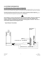
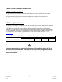
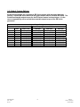
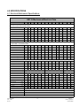
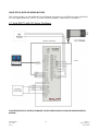
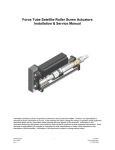
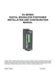
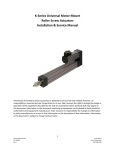
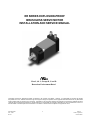
ER SERIES EXPLOSION-PROOF
BRUSHLESS SERVO MOTOR
INSTALLATION AND SERVICE MANUAL
Class I, div 1, Groups B, C and D
Hazardous Environment Rated
Information furnished by EXLAR Corporation is believed to be accurate and reliable. However, no responsibility is assumed by EXLAR
Corporation for its use. EXLAR reserves the right to change the design and operation of the equipment described herein and any associated
motion products that may appear in this document. Information in this document pertaining to equipment not furnished by EXLAR should be
confirmed by that equipment manufacturer. EXLAR assumes no responsibility for changes to information by other manufacturers or errors in
that information or the description of that information. Information in this document is subject to change without notice.
ER Manual.doc
PN: 23943
Rev B
1
06/2011
Exlar Corporation
855-620-6200
TABLE OF CONTENTS
1.0 Introduction
1.1 Warranty and Limitations of Liability
1.2 Safety Considerations
1.3 Explosion-Proof Classifications
2.0 System Configuration
2.1 Typical System Configuration
2.2 Feedback Information
3.0 Installation and Operation
3.1 Mounting Configurations
3.2 Mounting Considerations
3.3 Output Torque Ratings
4.0 Specifications
4.1 Electrical/Mechanical Specifications
4.2 ER Series Motor and Gear Stage Inertia
5.0 Troubleshooting Procedures
6.0 Installation
6.1 Exlar ER115 with Exlar SV Series Digital Positioner
ER Manual.doc
PN: 23943
Rev B
2
06/2011
Exlar Corporation
855-620-6200
1.0 INTRODUCTION
1.1 Warranty and Limitation of Liability
EXLAR warrants its product(s) to the original purchaser and in the case of original equipment
manufacturers, to their original customer to be free from defect in material and workmanship and to be
made in accordance with Exlar’s specifications for the product(s) as published at the time of purchase
unless otherwise agreed to in writing by an authorized Exlar representative. In no event shall EXLAR be
liable or have any responsibility under such warranty if the products have been improperly stored,
installed, used or maintained, or if Buyer has permitted any unauthorized modifications, adjustments
and/or repairs to such product(s).
Seller's obligation hereunder is limited solely to repairing or replacing (at its option), at the factory, any
product(s), or parts thereof, which prove to Seller's satisfaction to be defective materials or workmanship,
and within the period of time in accordance with the seller's stated product warranty (see terms and
conditions), however, that written notice of claimed defects shall have been given to EXLAR within 30
days from the date any such defect is first discovered. The product(s) or part(s) claimed to be defective
must be returned to EXLAR, transportation prepaid by Buyer, with written specification of the claimed
defect.
Components such as seals, wipers, bearings, bushings, gears, splines and roller screws are considered
wear parts and must be inspected and serviced on a regular basis. Any damage caused by failure to
properly lubricate EXLAR products and/or to replace wear parts at appropriate times is not covered by
this warranty.
THE FOREGOING WARRANTY IS IN LIEU OF ALL OTHER WARRANTIES (EXCEPT AS
TITLE), WHETHER EXPRESSED OR IMPLIED, INCLUDING WITHOUT LIMITATION, ANY
WARRANTY OF MERCHANTABILITY, OR OF FITNESS FOR ANY PARTICULAR PURPOSE,
OTHER THAN AS EXPRESSLY SET FORTH AND TO THE EXTENT SPECIFIED HEREIN, AND IS
IN LIEU OF ALL OTHER OBLIGATIONS OR LIABILITIES ON THE PART OF EXLAR.
SELLER'S MAXIMUM LIABILITY WITH RESPECT TO THESE TERMS AND CONDITIONS AND
ANY RESULTING SALE, ARISING FROM ANY CAUSE WHATSOEVER, INCLUDING WITHOUT
LIMITATION, BREACH OF CONTRACT OR NEGLIGENCE, SHALL NOT EXCEED THE PRICE
SPECIFIED HEREIN OF THE PRODUCT(S), GIVING RISE TO THE CLAIM, AND IN NO EVENT
SHALL EXLAR BE LIABLE UNDER THE TERMS OF THE WARRANTY OTHERWISE FOR
SPECIAL, INCIDENTAL OR CONSEQUENTIAL LOSSES RESULTING FROM INABILITY TO
USE THE PRODUCT(S), INCREASED OPERATING COST, LOSS OF PRODUCTION, LOSS OF
SPECIAL INCIDENTAL OR CONSEQUENTIAL DAMAGES, WHETHER SIMILAR OR
DISSIMILAR OF ANY NATURE ARISING OR RESULTING FROM THE PURCHASE,
INSTALLATION, REMOVAL, REPAIR, OPERATION, USE OR BREAKDOWN OF THE
PRODUCT(S), OR ANY OTHER CAUSE WHATSOEVER INCLUDING NEGLIGENCE.
The foregoing warranty shall apply to products or parts that have been repaired or replaced pursuant to
such warranty, and within the period of time, in accordance with the Seller's stated warranty.
No person including any agent of EXLAR, is authorized to make any representation of warranty on behalf
of EXLAR concerning any products manufactured by EXLAR, except to refer to this warranty.
ER Manual.doc
PN: 23943
Rev B
3
06/2011
Exlar Corporation
855-620-6200
1.2 Safety Considerations
As with any electro-mechanical device, safety should be considered during the installation and
operation of your ER Series brushless servo motor. Throughout this manual you will see
paragraphs marked with CAUTION and WARNING signs as shown below.
CAUTION
WARNING
Pay particular attention to these paragraphs. They are intended to provide you with helpful
information to ensure safe and trouble-free installation.
1.3 Explosion-Proof Ratings
ER Series motors are rated for Class 1, div 1, Groups B, C and D. The classification of "Class 1" means
that flammable gases or vapors may be present in the air in quantities sufficient to produce explosive or
ignitable mixtures. "Division 1" means that hazardous concentrations in the air may exist continuously,
intermittently, or periodically under normal operating conditions. "Group B" allows for atmospheres
containing hydrogen, or gases (or vapors) of equivalent hazard, such as manufactured gas. "Group C"
allows for atmospheres containing ethyl-ether vapors, ethylene or cyclo propane. "Group D" allows for
atmospheres containing gasoline, hexane, naptha, benzene, butane, alcohol, acetone, benzol, lacquer
solvent vapors, or natural gas. ER Series motors are not rated for operation in atmospheres
containing acetylene.
It is the responsibility of the user to provide for properly rated conduit connections to the ER
Series motor or gearmotor. Exlar takes no system responsibility beyond the motor or
gearmotor ratings.
ER Manual.doc
PN: 23943
Rev B
4
06/2011
Exlar Corporation
855-620-6200
2.0 SYSTEM CONFIGURATION
2.1 ER Series Servo Motor System Configuration
The design of the ER Series motor and selection of the proper feedback configuration allows it to be powered by
nearly any brand of brushless motor amplifier on the market that powers brushless motors with resolver feedback.
Each brand of brushless motor amplifiers may have unique wiring requirements, parameter settings and
operational principles that affect how the motor operates. Details on connections to specific brands of amplifiers
can be obtained from Exlar applications engineering or from Section 6.0.
Never attempt to connect or disconnect the motor with power applied. Dangerous voltages are
present. Damage to equipment and injury to personnel can result. Many amplifiers have
voltage present for a considerable time period after incoming power is removed. Take care to
insure that the amplifier has discharged all power.
Typical System Connections
ER Manual.doc
PN: 23943
Rev B
5
06/2011
Exlar Corporation
855-620-6200
2.2 Feedback Information
Standard ER Series motors use resolvers as their primary feedback device. Depending on the amplifier
that will be used to operate the actuator, the hookup of the actuator can vary. Always consult Section 6.0
for proper wiring, or contact Exlar for the correct wiring details. Most ER Series motors incorporate a 2
pole resolver with commutation signals as the primary rotary feedback device. The selection of this
feedback device is dictated by the amplifier that the end user will use to operate the motor. This amplifier
is indicated in the model number of the ER Series motor as a 3 digit code consisting of 2 letters and 1
number.
Each amplifier has specific requirements for the feedback on the motor. Not all resolver-based amplifiers
can use the same resolver, resolver alignment, or relative direction of resolver rotation.
Many amplifiers offer software that allows the entering of parameters or the downloading of "motor data
files" that dictate how the feedback must be set up on the motor. Exlar can provide many of these "data
files" or the proper parameters to enter. Entering motor parameter data to some amplifiers may require
assistance from the amplifier manufacturer.
Feedback Alignment
When Exlar manufactures an ER Series motor, the proper feedback is selected, mounted, aligned and test
run on the amplifier that the customer plans to use, or one that is known to be equivalent for confirming
proper feedback alignment and operation. In any case where it is determined that the feedback has become
mis-aligned, or an amplifier change is made requiring the feedback to be aligned differently, it is
recommended that Exlar be contacted and arrangements made to have that procedure performed.
Feedback Wiring
The wiring of the feedback device is critical to the operation of the motor with the selected amplifier. Miswiring the feedback cable can cause unstable operation, incorrect operation or no operation at all. In some
cases, if the proper current limits are not set in the amplifier, mis-wiring of the feedback cable can lead to
damage of the motor.
Resolvers
A resolver is a non-electronic device that works like a small transformer. When rotated, it generates two
sine waves that are out of phase with one another. By decoding these two sine waves, the amplifier can
monitor the direction, revolutions traveled and speed of rotation of the motor. Each sine wave typically
represents one revolution of the motor, so the amplifier can also use these signals to know where the motor
is within that revolution. By knowing the motor's position, the amplifier can properly time the supply of
current and voltage to the motor for it to rotate. This process is commutation. For the amplifier to
properly commutate the motor, it must have a reference, or zero, point from which to track the motor's
rotation. This reference point is critical, and is provided to the amplifier through the proper alignment of
the resolver to the phases of the motor during the actuator assembly.
ER Manual.doc
PN: 23943
Rev B
6
06/2011
Exlar Corporation
855-620-6200
3.0 INSTALLATION AND OPERATION
3.1 Mounting Configurations
The ER Series standard mounting configurations and dimensions can be obtained from the product
catalog or from our website, www.exlar.com.
The typical fasteners used to mount via the front through holes of the ER Series actuators are:
ER 115: M8 or 5/16” SHCS
3.2 Mounting Considerations
As with any motor product, misalignment of the ER Series motor with respect to whatever load the motor
is being used to move is of great concern. Any misalignment will decrease the life of the components
within the motor and also may create problems within the application associated with misalignment.
Therefore every effort should be made to minimize misalignment as much as is possible. Also, mounting
of pulleys and similar devices on the output shaft of the motor imparts side load on the output shaft. The
life of the gear stage of the actuator is dependant on side load as shown in the table below. Visit
www.exlar.com for more detailed tables.
ER115
Radial Load for 10,000 hour bearing life at 25mm from motor face
RPM
50
100
250
500
Lbf (N)
939 (4177)
745 (3314)
549 (2442)
435 (1935)
1000
346 (1539)
Excessive side load on the output shaft of the motor will dramatically reduce the life of
the motor and should be avoided. Side load can be caused from misalignment, loading
from devices such as pulleys mounted directly to the output shaft, and from the motor’s
use in the application.
ER Manual.doc
PN: 23943
Rev B
7
06/2011
Exlar Corporation
855-620-6200
3.3 Output Torque Ratings
ER Series gearmotors are equivalent to ER Series motors with integrated planetary
gearing. Consult ER Series electrical and speed torque data for use with ER ratios. The
maximum allowable output torque for the ER Series motors is shown below. It is the
user’s responsibility not to exceed the acceptable output torque of the ER Series
gearmotor.
Output Torque Ratings
Output Torque @ Indicated RPM for 10,000 Hour Life
Ratio
ER115
ER Manual.doc
PN: 23943
Rev B
4:1
5:1
10:1
16:1
20:1
25:1
40:1
50:1
100:1
Maximum
Static Load
Lbf-in (Nm)
4696 (530.4)
4066 (459.4)
2545 (287.5)
4696 (530.4)
4696 (530.4)
4066 (459.4)
4696 (530.4)
4066 (459.4)
2545 (287.5)
1000 RPM
Lbf-in (Nm)
1392 (157.3)
1445 (163.3)
1660 (187.6)
2112 (238.6)
2240 (253.1)
2350 (265.5)
2800 (316.4)
2900 (327.7)
2500 (282.5)
8
2000 RPM
Lbf-in (Nm)
1132 (127.9)
1175 (132.8)
1350 (152.6)
1714 (193.0)
1840 (207.9)
1900 (214.7)
2240 (253.1)
2350 (265.5)
2500 (282.5)
3000 RPM
Lbf-in (Nm)
1000 (112.9)
1040 (117.5)
1200 (135.6)
1518 (171.0)
1620 (183.0)
1675 (189.2)
2000 (225.9)
2100 (237.3)
2400 (271.2)
06/2011
Exlar Corporation
855-620-6200
4.0 SPECIFICATIONS
4.1 Electrical/Mechanical Specifications
ER115 Mechanical/Electrical Data
MOTOR STATOR
1A8
1B8
118
138
158
168
2A8
2B8
238
258
268
338
358
368
50.5
50.5
50.6
50.5
83.3
83.3
84.0
82.5
84.0
117.3
117.6
120.4
RMS Sinusoidal Commutation Data
Continuous Motor Torque* Lbf-in
49.7
49.7
Peak Motor Torque
Torque Constant (Kt)
(N-m)
5.61
5.61
5.70
5.70
5.72
5.70
9.41
9.41
9.49
9.32
9.49
13.25
13.29
13.60
Lbf-in
99.3
99.3
101.0
101.0
101.2
100.9
166.6
166.6
168.0
165.0
168.0
234.6
235.3
240.8
(N-m)
11.22 11.22 11.41
11.41
11.44
11.40
18.82
18.82
18.98
18.64
18.98
26.50
26.58
27.21
8.7
15.7
17.4
5.3
5.3
8.7
15.9
17.4
8.5
15.9
17.6
Lbf-in/A
5.3
5.3
4.3
0.6
0.6
0.5
1.0
1.8
2.0
0.6
0.6
1.0
1.8
2.0
1.0
1.8
2.0
Cont. Current Rating @ 80°C
A
10.5
10.5
13.0
6.5
3.6
3.2
17.6
17.6
10.8
5.8
5.4
15.4
8.3
7.7
Peak Current Rating @ 80°C
A
21.0
21.0
26.0
13.0
7.2
6.5
35.2
35.2
21.6
11.6
10.8
30.8
16.6
15.3
+/-10% @ 80°C
N-m/A
Trapezoidal Commutation Data
Continuous Motor Torque
47.4
47.4
48.2
48.2
48.3
48.2
79.5
79.5
80.2
78.8
80.2
112.0
112.3
115.0
5.36
5.36
5.45
5.45
5.46
5.45
8.99
8.99
9.06
8.90
9.06
12.66
12.69
12.99
230.0
Lbf-in
94.8
94.8
96.4
96.4
96.7
96.4
159.1
159.1
160.4
157.6
160.4
224.0
224.7
(N-m)
10.71
10.7
10.9
10.9
10.9
10.9
18.0
18.0
18.1
17.8
18.1
25.3
25.4
26.0
Lbf-in/A
4.12
4.12
3.39
6.78
12.22
13.55
4.12
4.12
6.78
12.37
13.55
6.63
12.37
13.70
(N-m/A)
0.47
0.47
0.38
0.77
1.38
1.53
0.47
0.47
0.77
1.40
1.53
0.75
1.40
1.55
Peak Motor Torque
Torque Constant (Kt)
+/-10% @ 80°C
Lbf-in
(N-m)
Cont. Current Rating @ 80°C
A
12.85 12.85 15.90
7.95
4.42
3.97
21.55
21.55
13.23
7.12
6.61
18.88
10.14
9.38
Peak Current Rating @ 80°C
A
25.69 25.69 31.81
15.90
8.84
7.95
43.10
43.10
26.46
14.23
13.23
37.76
20.29
18.76
51.1
51.1
42.0
83.9
151.4
167.9
53.1
51.1
83.9
153.3
167.9
82.1
153.3 169.7
36.1
36.1
29.7
59.4
107.1
118.7
36.1
36.1
59.4
108.4
118.7
58.1
108.4 120.0
8
8
8
8
8
8
8
8
8
8
8
8
8
8
Ohms
0.31
0.31
0.20
0.80
2.60
3.21
0.127
0.13
0.34
1.17
1.35
0.20
0.69
0.81
mH
4.8
4.8
3.3
13.0
42.4
52.1
2.3
2.3
6.3
21.1
25.3
4.0
13.9
17.1
Motor Stator Data
Voltage Constant (Ke) Vrms / Krpm
+/-10% @ 80°C
Vpk / Krpm
Pole Configuration
Resistance (L-L) +/-5%
Inductance (L-L) +/-15%
Armature Inertia
lbf-in-sec2
0.00555
Kg-cm2
Mech. Time Constant (tm), ms
min
6.27
0.53
0.53
0.52
0.54
0.52
0.43
0.42
max
15.73 15.73 16.26 16.26
16.34
16.25
18.41
18.41
18.72
18.06
18.72
20.08
20.19 21.16
ms
15.73 15.73 16.26 16.26
16.34
16.25
18.41
18.41
18.72
18.06
18.72
20.08
20.19 21.16
lbf-in/krpm
0.21
0.21
0.21
0.21
0.35
0.35
0.35
0.35
0.35
0.40
0.40
(N-m/krpm)
0.024 0.024 0.024 0.024
0.024
0.024
0.040
0.040
0.040
0.040
0.040
0.045
0.045 0.045
lbf-in
Bus Voltage
Vrms
Speed @ Bus Voltage
RPM
Motor Wire Insulation °C
(class)
0.56
0.21
0.56
0.82
12.56
0.82
(N-m)
0.85
9.42
0.82
Friction Torque
0.85
0.01112
0.82
Electrical Time Constant (te)
Damping Constant
0.00833
0.21
0.56
0.56
0.56
1.00
1.00
1.00
1.00
1.00
1.20
1.20
0.063
0.063
0.113
0.113
0.113
0.113
0.113
0.136
0.136 0.136
300
750
115
230
400
460
3000
3000
3000
3000
24VDC 48VDC
300
750
1.20
230
400
460
230
400
460
3000
3000
3000
3000
3000
3000
180(H)
Insulation System Voltage Rating
Thermal Switch, case temp.
0.40
0.063 0.063 0.063 0.063
24VDC 48VDC
0.56
0.40
460
°C
100
IP65
Environmental Rating
*For amplifiers using peak sinusoidal ratings, multiply RMS sinusoidal Kt by .707, and peak current by 1.414. Test data derived using NEMA 12" x 12" x 1/2" aluminum heat sink
ER Manual.doc
PN: 23943
Rev B
9
06/2011
Exlar Corporation
855-620-6200
4.2
ER Series Gearmotor Stage Inertia
ER115
Stator
1 Stack
2
2
2 Stack
3 Stack
ER Armature Inertia lb-in-sec (kg-m )
0.00344
(3.89)
0.00623
(7.036)
0.00901
(10.181)
ER Brake Inertia lb-in-sec2 (kg-m2)
0.00327
(3.70)
0.00327
(3.70)
0.00327
(3.70)
0.00538
(6.08)
0.00816
(9.22)
0.0109
(12.37)
2
2
ER Armature Inertia lb-in-sec (kg-m )
Reflected Inertias
Single Reduction
2
2
Reflected Inertias
Double Reduction
Gear Stages
lb-in-sec
(kg-cm )
Gear Stages
lb-in-sec2
(kg-cm2)
4:1
0.000635
(0.717)
16:1
0.000513
(0.580)
5:1
0.000428
(0.484)
20:1, 25:1
0.000350
(0.396)
10:1
0.000111
(0.125)
40:1, 50:1, 100:1
0.0000911
(0.103)
5.0 TROUBLESHOOTING PROCEDURES
This section provides you with guidelines and hints on troubleshooting various problems that may be encountered
during installation and operation of your Exlar ER Series motor.
Symptom / Trouble
Possible Cause / Troubleshooting Procedure
No response from motor.
1. Check amplifier for faults that may indicate problem.
2. Check to insure that amplifier is enabled
3. Check for proper wiring
1. Amplifier may be improperly tuned. Check all gain settings.
If a motor file, or parameters specific to your amplifier/motor
combination have been supplied by Exlar, be sure that they are
entered or downloaded properly.
2. Amplifier may be set up improperly for the particular motor being
used. Check amplifier settings for number of poles, voltage, current,
resistance, inductance, inertia,
3. Feedback wiring may be incorrect.
4. Feedback conductors touching, or feedback cable may be
damaged.
5. Motor phases are wired incorrectly or in incorrect order. (R,S,T)
6. Resolver feedback is improperly aligned. Contact Exlar.
1. Load is too large for the capacity of the motor or too much friction
is present.
2. Excessive side load.
3. Misalignment of output shaft to load.
4. Amplifier has too low of current capacity or is limited to too low of
current capacity.
1. Check motor mounting. Insure that the motor is securely mounted.
2. Amplifier is improperly tuned (wrong gain settings.) Tune amplifier.
Motor seems to be enabled
(receiving current) but is not
operating or is operating
erratically.
Motor cannot move load
Motor housing moves or
vibrates when shaft is in
motion.
Motor is overheating
1. Insufficient cooling for application requirements. Contact Exlar
engineering.
2. Motor is being operated outside of continuous ratings.
3. Amplifier is poorly tuned causing excessive unnecessary current to
be applied to motor. Check Gain settings.
6.0 SYSTEM INSTALLATION
ER Manual.doc
PN: 23943
Rev B
10
06/2011
Exlar Corporation
855-620-6200
DRIVE SET-UP WITH ER SERIES MOTORS
This section provides you with cable and wiring information for operation of your ER Series motor with Exlar's
SV Series Digital Positioner. (NOTE: If you use a different amplifier, contact Exlar for assistance.)
6.1 Exlar ER115 with SV Series Positioner
Resolver Feedback
Power
FOR DETAILED SETUP INSTRUCTIONS SEE THE SV SERIES INSTALLATION AND CONFIGURATION
MANUAL.
ER Manual.doc
PN: 23943
Rev B
11
06/2011
Exlar Corporation
855-620-6200