1
Platelet Storage System Manual
Model PC100
Version A
English
HELMER LABS, INC. 15425 HERRIMAN BLVD., NOBLESVILLE, IN46060 USA
PHONE (317) 773-9073 FAX (317) 773-9082
USA and CANADA
1-800-743-5637
Operation Manual
Installation
Page
2
/ ! \ - Labeling
2
Controls and Components
3
Temperature and Alarm Systems
4
A.
B.
C.
D.
E.
Digital Temperature Controller
Accessing the Chamber Set Temperature
Accessing the Low and High Alarm Programs
Alarm Timer Delay
Power Failure Alarm
Quality Control
6
A. Calibration of the Digital Controller
B. Alarm System Test
Specifications
8
Description of Symbols
8
Maintenance
8
Cleaning
9
Troubleshooting
10
Warranty
12
Appendix (Figures, List of European distributors where applicable)
1-3 6003 7/C
Installation
1) Carefully unpack your Helmer Platelet Incubator.
Included in the carton is a bag with the following accessories:
1) Power cord.
2) 16mm tube for Quality Control testing. Refer to the Quality Control section.
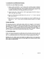
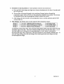
3) Fan cover for Agitator. This directs the hot air from the Agitator. Remove the
backing on the adhesive strips and press this in place onto your Agitator as shown
(Figure 0.0) so that the open side of the box is facing the back of the unit.
2) Select a location keeping the following in mind:
1) Allow 4 inches (10 cm) of air space above and to the right side of the unit for
adequate air circulation. Use a grounded outlet with adequate power specifications as
listed on the specifications label on the back of the unit.
2) Keep away from direct sunlight or high temperature areas.
3) Turn the power switch to "I" (ON) and allow the chamber temperature to stabilize (30
minutes) at the factory preset controller values. While waiting for the chamber temperature
to stabilize, carefully continue reading through the instruction manual.
4) Open the door to the chart recorder and connect the leads to the 9 volt battery.
5) Insert an approved, calibrated thermometer on the top shelf of your flatbed platelet agitator.
6) To install platelet agitators, open the incubator door and carefully place the platelet agitator
onto the center of the incubator. Plug the platelet agitator power cord into the chamber
outlet. Make sure that the power cord is properly secured to prevent cord damage. Turn the
platelet agitator power switch to the on position and verify that it is centered within the
drawer.
J\
-Labeling
(Figure 0.1) - The maximum amperage rating for the interior chamber outlet (1), is 0.5 amps. Do
not plug any device into the outlet that exceeds this rating.
1-3 6003 7/C
Controls and Components
Control Panel: The main control panel contains the following:
See Figure 1.1 in the Appendix for locations of components referenced below.
Digital Controller (1): Provides visual readouts and controlling of the chamber
temperature, alarms and other pertinent functions. All settings and calibration inputs are
made through the controller touch buttons.
Audible Alarm (2): Generates a tone when activated, signaling an alarm condition.
Main Power Switch (3): Controls all electrical current to the unit. When the switch is
turned to "I" (ON) the refrigeration, heating, fans and electrical systems become
operative. All unit functions are shut down when the main power switch is turned to "O"
(OFF).
Alarm Interrupt Button (4): Pressing this button when the audible high/low alarm has
sounded will temporarily silence the audible alarm by resetting the alarm time delay
period.
Audible Alarm Shutoff Switch (5): The audible alarm can be silenced with the key
activated shutoff switch. The unit is shipped with the switch in the "O" (alarm OFF)
position. Turn the switch to the "I" (alarm ON) position to activate the alarm.
Refrigeration and Heating System: The chamber is cooled by a refrigeration system in which
the compressor unit runs continuously. A heater is turned on by the controller system to maintain
the proper set temperature.
Thermostat Switch: A high temperature switch is mounted behind the interior back wall to
discontinue power to the heater in the event of heating circuit failure.
1 -36003 7/C
Temperature and Alarm Systems
A. Digital Temperature Controller
Your Helmer system incorporates a digital controller system and RTD sensor to accurately
control the temperature of the chamber. The controller system provides visual readouts of the
chamber operating temperature, alarm system, heater output, and other functions. All
temperature, calibration, and alarm settings are made through the controller touch buttons.
See Figure 2.1 in the appendix for locations of the items referenced below.
Heater On Indicator (1): This small round light labeled "1", will light whenever the
controller sends power to the heater. This indicator will light on and off continuously
during normal use.
Alarm Indicator (2): When the controller senses that the chamber temperature has
exceeded the high or low alarm limit the Alarm Indicator, labeled as "2", will illuminate.
The audible alarm is delayed for the period of time set by the Alarm Timer Delay. The
adjustable Alarm Timer Delay prevents unnecessary warnings that may be caused by
temporary temperature fluctuations when opening the doors.
Down Button ( v ) (3): Used to decrease the controller digit values in conjunction with
the SET button and to enter into the program functions in conjunction with the ^ button.
Up Button ( ^ ) (4): Used to increase the controller digit values in conjunction with the
SET button and to enter into the program functions in conjunction with the ^ button.
SET Button (5): Used to display the set temperature and to display the program function
values.
B. Accessing the Chamber Set Temperature
To alter the chamber temperature setting:
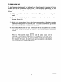
1) (Figure 3.1) This is the normal display of the current temperature reading.
2) (Figure 3.2) Press and hold the SET button to display the current set temperature value.
3) (Figure 3.3) While holding the SET button down, press either the A o r T button to alter
the set value as desired. (If the set value will not change, the Set Point Lockout is in the
lockout mode. To unlock this program value refer to "Accessing the Set Point Lockout"
in the Controller Lockout section of the Maintenance and Service manual.)
4) Release the SET button to complete the chamber temperature setting change.
1-360037/C
C. Accessing the Low and High Alarm Programs.
To alter the Low and/or High Alarm settings:
1) (Figure 4.1) Press and hold the ^ and ^ buttons until a controller program is displayed.
(If the "CnFg" prompt appears, the Controller Program Lockout will need to be unlocked.
To unlock this program value refer to "Accessing the Controller Program Lockout" in the
Controller Lockout section of the Maintenance and Service manual.)
2) (Figure 4.2) Press the ^ button until the "ALO" program appears for the Low Alarm, or
"Ahl" for the High Alarm program.
3) (Figure 4.3) While holding the SET button down, press the
alarm value as desired.
A
o r T button to alter the
4) (Figure 4.4) To exit back out to the main operating mode, release the SET button and
press both the ^ and ^ buttons until the operating temperature appears on the digital
display.
D. Alarm Timer Delay
The temperature alarm has a variable delay setting, which can be changed to set the length of
time desired before activating the audible and central alarm relays. The time can be set from
approximately 0 to 8 minutes. You can access this feature by removing the front panel of the
unit. The adjustment is made through the dial located on the internal circuit board (Figure 5.1).
Turning the dial to its extreme clockwise position sets the delay time to 8 minutes. Turning the
dial to its extreme counter-clockwise position sets the delay time to 0 minutes.
E. Power Failure Alarm
In the event of a power interruption the audible alarm will sound and the central alarm relay will
activate. To disable this alarm use the keylock switch located on the front control panel of the
unit. It is recommended to place the key for this switch in a location separate from the switch.
Disabling the power failure alarm also disables the audible portion of the temperature
alarm. However, in this disabled mode the red alarm light on the controller and the central
alarm output are still functional.
1-360037/C
Quality Control
A. Calibration of Digital Controller
To verify that the digital temperature controller is calibrated correctly allow the chamber
temperature to stabilize and then take a temperature reading from a calibrated thermometer
placed on the top shelf of the agitator inside the chamber. The temperature controller is
calibrated correctly if the thermometer reads the same as the controller display. The temperature
controller needs to be calibrated if there is a temperature variance.
As an example, if a calibrated thermometer reads 21.0°C and the Temperature Controller reads
22.0°C, then the controller display ("CAL" function) needs to be reduced by 1.0°C. If the
thermometer reads 23.0°C and the Temperature Controller reads 22.0°C, then the controller
display ("CAL" function) needs to be increased by 1.0°C.
To recalibrate the Temperature Controller:
1) (Figure 7.1) Press and hold the ^ and ^ buttons until a controller program is displayed.
(If the "CnFg" prompt appears first, the Controller will need to be unlocked. To unlock
this program value refer to "Accessing the Program Lockout" in the Controller Lockout
section of the Maintenance and Service manual.)
2) (Figure 7.2) Press the ^ button until the "Pid" Menu prompt appears.
3) (Figure 7.3) While pressing the SET button (the digital readout will display "no"), press
the ^ button to display "yes", and then release the SET button.
4) (Figure 7.4) Press the ^ button once to display the "CAL" prompt.
5) (Figure 7.5) While holding the SET button down, press either the
the calibration program value.
A
or
T
button to alter
6) (Figure 7.6) To exit back to the main operating mode, release the SET button and press
the A and ^ buttons simultaneously until the operating temperature appears on the
digital display.
After making any calibration changes to the Temperature Controller allow the chamber
temperature to stabilize and make a new reading to verify that the controller is properly
calibrated. Make any additional adjustments as needed until the controller readout is properly
calibrated.
1-360037/C
B. Alarm System Test
To test for proper functioning of the High and Low Alarm System it is important to follow
methods that may be recommended by the AABB or other governing organizations for such
alarm system checks. A suggested method to activate an actual alarm test condition is as
follows:
1) Fill the supplied 16mm tube with water that is at least 1°C beyond the alarm setting to be
tested.
2) Place the tube in the holding bracket and slide it up to submerse the end of the probe in
the water. (Figure 8.1)
3) Watch for the alarm indicator light on the Temperature controller to illuminate when the
temperature reading passes the alarm set point. The audible alarm will then go into the
delay mode and sound after the delay period has cycled.
4) Remove the tube and empty the water. Do not leave the tube in a position that covers the
RTD sensor. Doing so will cause the controls to take incorrect chamber temperature
readings.
Caution
When the RTD sensor is placed into the water the control system will be
responding as if the chamber temperature is the temperature of the water. As a
result, the system will adjust to this input accordingly and the actual temperature
of the chamber will change. Be careful not to expose any platelets in the chamber
to an extended period of varying temperatures.
1-360037/C
Specifications
Weight:
48 kg
Input Power:
115 / 230 V~, 50/60 Hz
Consumption:
920 VA
Includes the load from standard agitator placed inside the
chamber.
Circuit Breakers:
115 V: 12 A
230 V: 6 A
Size:
53 cm (W) x 63 cm (H) x 43 cm (D)
Operating Temperature:
+5 up to +35°C
This device complies with CSA standard 151 and UL standard 1252 for construction and
electrical safety.
Description of Symbols
C€
- Conforms to 93/42/EEC
I—I
- Date of Manufacturing
Maintenance
It is recommended to conduct the following maintenance items to help keep your Helmer
Platelet Incubator in good working condition:
Quarterly:
Clean condenser grill.
Conduct alarm and calibration checks.
Check the 9V-chart recorder battery.
1-360037/C
Cleaning
The importance of proper cleaning of your Helmer Platelet Incubator cannot be under estimated.
Lack of cleaning of items, such as the condensor fins, can significantly cut down on the life
expectancy of this equipment.
Exterior - A soft cotton cloth and non-abrasive liquid cleaner should be used for cleaning the
exterior surfaces. The door should be cleaned with a soft cotton cloth and window cleaner. The
black condensor fins located on the upper right side of the unit should be cleaned and vacuumed
often.
Interior - Always turn the power switch off when cleaning the interior of the incubator. A
disinfectant cleaner should be used to wipe down the inside stainless steel walls, drawer and
interior water drain tray. This should be done on a regular basis or when leaking bags require
you to clean the chamber.
1-3 60037/C
Troubleshooting
The information in this section is for the benefit of the user in diagnosing certain issues. If the
user cannot resolve a particular problem your service agent may use the more extensive
Troubleshooting section in the Service Manual. Contact HELMER or your authorized service
representative if more help is needed.
***Electrical***
Problem
Unit does not turn on.
Platelet agitator not
operating.
Power cord on agitator
rubbing.
Possible Cause
Action to be Taken
Circuit breaker or fuse
activated.
- Reset circuit breaker or replace fuse.
Faulty outlet connection.
- Verify outlet is good. Plug into a
different outlet.
- Faulty power cord.
- Verify proper cord connections.
Change power cord.
- Faulty power switch.
- Replace switch.
- Faulty platelet agitator.
- Verify that agitator is working
properly.
Agitator not centered in
chamber.
- Verify positioning of agitator.
Power cord not positioned - Verify positioning of cord,
properly.
1-3 60037/C
10
***Alarms and Controller***
Audible alarm not
sounding.
Alarm sounding
sporadically.
Not waiting for alarm
delay to cycle.
• The alarm system has a delay system
before the audible alarm will sound.
Wait sufficient time for alarm delay
to cycle.
Verify Alarm and
Controller settings.
• The controller alarm value or other
values may have been altered
causing the non-alarm condition.
Refer to the proper controller value
settings and change accordingly.
- Faulty alarm system.
• Verify proper operation of the
controller, secondary circuit board
and line connections.
Alarm deviation value set
too tight.
During normal operation the
temperature will fluctuate as a result
of many factors. If the alarm value
is set too tight to the operating value
the alarm may sound often. The
alarm system is to warn of serious
unit temperature fluctuations.
Increase the alarm value.
Door not closing.
Verify proper alignment of door
closure.
Verify door gaskets are sealing
properly.
Air gaps around door.
Chamber temperature not
stabilizing.
Verify that the chamber temperature
is maintaining a proper and
consistent temperature. Refer to
Quality Control section.
Alarm not activating at
proper temperature.
- Calibrate controller.
Refer to section on Calibration of the
Digital Controller.
Controller setting not
calibrated properly.
- Calibrate controller.
Refer to section on Calibration of the
Digital Controller.
1-3 6003 7/C
11
***Other***
Ice lying in water tray.
- Refrigerant pressure is
low.
- Verify refrigerant pressures. Add
refrigerant as needed.
Severe water puddling in
water tray.
- Drain hole plugged.
- Unclog drain hole.
Door not closing tight,
allowing humid air into
the chamber.
Water is puddling outside - Drain pan leaks.
of the incubator.
- Water is condensing on
evaporator lines to the
compressor.
Platelets are "pooling" to
one side of the bag.
Verify that door gasket is sealing and
door is closing properly.
Seal any leaks in drain pan with
silicone.
• Apply additional cork tape to copper
lines.
- Excessive humidity.
Water will accumulate more during
humid periods. Make sure door is
closing properly.
- Unit not level.
Verify that the unit is sitting level.
Verify that the agitator is sitting
level.
Limited Warranty
(USA and Canada)
The Helmer Platelet Incubators are warranted for one year for materials and labor at our factory.
(For all other countries contact your local distributor.)
1-3 60037/C
12
1-360039/B
0.1
<D
1-360039/B
3.3
3.2
3.1
r
221
01
02
OFtY
1-360039/B
1-360039/B
1-360039/B
Service Manual
Version A
Model PC100
Page
Central Alarm Hook-up
2
Remote Probe Installation
2
Temperature Controller Programs
3
Controller Lockout System
5
Controller Error Codes
8
Parts List
9
Refrigeration Recharging Chart
10
Wiring Schematic
11
Troubleshooting
16
A. Electrical
B. Alarms and Controller
C. Chamber Temperature
D. Other
1-360038/E
Central Alarm Hook-up
The central alarm hookup described in this section is for the high/low alarm and the power
failure alarm. By using this system you are connecting to a relay switch, either normally open
or normally closed, depending on terminals used. There is no voltage output provided from this
connection. To connect a central alarm system into the platelet incubator's high/low alarm
outputs you will need to do the following:
1) Turn the power switch off and unplug the unit.
2) Remove the front panel.
3) Locate the three terminals on the right side of the secondary circuit board. These three
outputs are for connecting to a central alarm system. The outside terminal (#16) is the
common, the next terminal to the left (#15) is the normally closed contact and the second
terminal to the left (#14) is the normally open contact.
4) Connect the central alarm wires to the proper terminals for your alarm system.
5) Cable tie the wires as necessary for stability.
6) Run the central alarm wires through the small grommet located in the back of the exterior
panel that was removed.
7) Replace the panel.
To connect a central alarm system to the agitator alarm in the platelet incubator, see the agitator
or motion alarm instructions. A hole is provided on the right side of the chamber wall for wire
access to the chamber. Remove the plug on the exterior side of the wall for access.
Remote Probe Installation
To install a third party probe for monitoring or for a supplemental temperature alarm system you
will need to do the following:
1) Locate the chamber access hole on the right side of the chamber wall. It is shipped with a
hole plug in it.
2) Remove the hole plugs and run the probe through the wall. Depending on the diameter of
your probe you may want to drill a hole in the hole plugs and run the probe through those so
that the plugs can be replaced in their positions.
3) Locate the two screws on the bottom edge of the rear wall. These two screws are for use in
mounting the probe. You may use both or just one depending on the length of the probe.
Mount the probe.
4) Seal the access hole in the right wall. If the hole plugs are reused pack the cavity in the wall
with a filler material.
Note: For accurate readings of the supplemental system you install using the above probe it is
important to locate the probe in this position.
1-3 6003 8/E
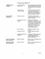
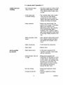
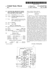
Temperature Controller Programs
The digital controller contains internal programs that effect the operation and accuracy of the
controller and alarm system. A few of the internal programs may be altered by the operator for
specific requirements and are noted below by an asterisk (*). The remaining program
functions must not be altered without consulting Helmer - doing so could effect the
operation of the unit and the manufacturer's warranty. The following is a summary of the
controller's internal programs with their description and proper value settings:
Main Program
Titles and Access
1. Operating Set Temp.
Press SET button
2. Operations Menu
Press ^ and ^ buttons
together for 3 seconds
3. PID Menu
Change the "Pid"
Menu setting to "yes"
4. Configuration Menu
Change the "CnFg"
Menu to "yes"
Program
Description
Program
Display
Chamber Set Temperature
Program
Value
*22.0
Auto-tune
Low Alarm Deviation
High Alarm Deviation
PID Menu
Configuration Menu
Aut
ALO
Ahl
Pid
CnFg
no
*20.0
*24.0
no
no
Proportional Band
Cycle Time
Integral Function
Derivative Function
Calibration Offset
Pbh
Cth
It
dE
CAL
1.0
0.5
30.00
0.80
*varies
Input Type
Celsius
Temperature Low Limit
Temperature High Limit
Output 1 Function
Output 2 Function
Display Default
Alarm Type
Alarm Hysteresis
Alarm Latch
Alarm Silencing
Failure Mode
Set Point Lockout
Controller Lockout Tag
In
C F
rL
rh
Otl
Ot2
dISP
ALty
AhyS
LAt
SIL
FAIL
SLOC
tAg
Rtd
°C
15.0
35.0
hEAt
ALr7
Ac
Prno
0.1
no
no
bPLS
*no
C A
1-360038/E
ECO
1
r
REV !
DATE
I REVISION DESCRIPTION
r in
j J> J j i
T l
i
1J
^
fLOCI ED
•— R u b
J HLD
Rh
>i P i d r
I
[n F9
TO R[TURN TO
TEMP DISPLAY.
(SET
NO
NO
LO TEMP
HI 1EMP
AL ARM
ALARM.
_YF?
LOniLEI)
.!
Ph h
Th h
r
L_
7TT
CRL
Db
TO RETURN 10
TEMP DISPLAY
nLby
bR9
XFF
5~iT
FR I L
o
o
|PEDR[
|__C___RJ
(FULL LOCKOUT)
(FACTORY LOCKOUT)
TO RETURN TO
TEMP D I S P L A Y
To unlock refer to "Accessing the Controller Program Lockout".
C0NPR01
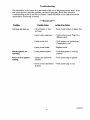
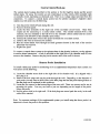
Controller Lockout System
A) Factory Lockout Mode:
tag = (_C_A)
The digital Temperature Controller has been set in a "factory lockout" mode. This means
that the user can access the Set Temperature, Low and High Alarms, Calibration Offset
and the Controller Lockout program values.
B) Full Lockout Mode:
tag = (PCOA)
If the Controller Lockout is set to "PCOA" then all controller programs will be inaccessible,
except the Set Temperature.
C) Unlocked Mode:
tag = (
)
If the Controller Lockout Tag is set to "
accessible to the user.
", then all controller programs will be
D) Set Point Lockout:
(SLOC) = "yes" or "no"
If the Set Point Lockout is set to "no", the operating set temperature can be changed by the
user. If the Set Point Lockout is set to "yes", the operating set temperature is locked and
can not be changed.
1) Accessing the Controller Program Lockout:
1) Press and hold the ^ and ^ buttons until a controller program is displayed. If the
lockout is in the factory lockout setting, the first controller program to appear will be
"ALO". If the " Aut" prompt appears, the controller programs are fully unlocked. If the
"CnFg" prompt appears, the controller programs are fully lockout.
2) Press the
A
o r T button until the "CnFg" prompt appears.
3) While pressing the SET button in (the digital readout will display "no") press the ^ or
^ button to display "yes", and then release the SET button. If the "In" prompt appears,
proceed to step 4. If the "tAg" prompt appears, you are at the program display for the
Controller Lockout Tag, proceed to step 5.
Caution
Do not change the "In" or "°C" program values. Doing so automatically changes
many of the controller program values causing uneven temperature controlling of
the incubator.
4) Press the ^ button once to display the "tAg" prompt. You are now at the program
display for the Controller Lockout Tag.
5) Press and hold the SET button to display the current input value of the "tAg" program.
6) To change the lockout program value, hold the SET button down and press the
button to change the program value.
7)
A
orT
To exit back to the main operating mode, release the SET button and press both the
^ and ^ buttons until the operating temperature appears on the digital display.
1-360038/E
2) Accessing the Set Point Lockout (SLOC):
1) With the controller fully unlocked, (refer to steps 1-6 in the Accessing the Controller
Program Lockout), press and hold the ^ and ^ buttons until a controller program is
displayed.
2) Press the
A
or
T
button until the "CnFg" prompt appears.
3) While pressing the SET button in (the digital readout will display "no"), press the ^ or
v
button to display "yes", and then release the SET button. The "In" prompt will
appear.
4) Press the ^ button twice to display the "SLOC" prompt. You are now at the program
display for the Set Point Lockout.
5) Press and hold the SET button to display the current input value of the Set Point program
- either "yes" or "no" will be displayed. The "yes" prompt means that the Set Point
Lockout is in the Lockout mode. The "no" prompt means that Set Point Lockout is
Unlocked.
6) To exit back to the main operating mode, release the SET button and press both the ^
and ^ buttons until the operating temperature appears on the digital display. If you want
to reset the lockout function, do so before returning to the main operating mode.
7) To change the program value simply hold the SET button in while pressing either the ^
or ^ button once.
1-36003 8/E
! ECO
RTF'"LLEP
HP I T 1?
I JL j[ A J
TO
ACCESS
T H E (. O N T R O L l . E R P R O G R A M S
TLMP
PP
^T1
T
I
"
11
^ 1
i
R E L E R T O T H L
RLD
!R E v l
D A TTE
REVISION DESCRIPTION
)
I - i T ALODF
" CONT R O L L E R P R O O R A M LL O W C H A R [
Rh I
P.d
HI T E M P
ALARM
Ph_h_
-««
|»>~
CnF3
(SET'
j_
IIITITIT11TT
LO TEMP
Al ARM.
; E I TEMP
'IT/
TfFh
dE
CRL
fi
SET
TEMP LOCKOUT
(SLOC)
WHEN THE SLOC VALUE IS
NO THE SET TEMP VALUE
CAN BE CHANCED.
PROGRAM LOCKOUT (TAG)
o
o
#2
—VZZ\
WHEN THE TAG. VALUE IS
-C._A NONE OF THE VALUES
THAT ARE SHADED ( Y/7//} )
CAN BE ACCESSED OR CHANCED.
C0NPR03
Error Codes
The temperature controller can diagnose certain problems and communicate the diagnosis
through error messages on the digital readout.
Error Code
Problem
Erl
Reversed RTD sensor wires
Er2
Er3
Incorrect input value ("In") in the configuration menu
- or - Open RTD sensor circuit
RTD sensor type mismatch
Er4
Open RTD sensor circuit (bad connection, broken wire)
1-360038/E
Parts List
Model PC100
To order parts for your Helmer Platelet Incubator, indicate the quantity, part number and
description with your purchase order number. Please provide the model number and serial
number as well.
Description
Digital Controller
Audible Alarm
On/Off Power Switch
Chart Recorder
Chart Recorder Paper - 4 inch (52/box)
Alarm Delay Switch
Audible Alarm Shutoff Switch
Heater Thermostat
Secondary Circuit Board
Chamber Electrical Outlet
Chamber Heater
Chamber Fan
Compressor
Condensor Fan Motor
Circuit Breaker
Part Number
115 Volt
230 Volt
120074
120313
120009
400333
120178
120259
120097
120314
120010
400334
120309
120288
400324
120160
120158
400409-1
220273
120197
120227
120250
400320
1-36003 8/E
Refrigeration Recharging Chart
Approximate recharging weight is 5 oz. (Note: Refrigerant is R134A)
After recharging follow the procedure below:
Allow the incubator chamber temperature to stabilize at 22.0 degrees C. With a pressure gauge
set on the refrigeration lines, the refrigerant pressure should be as follows:
Room Temperature
c
18
19
20
21
22
23
24
25
26
27
28
29
30
Low Side (suction) Pressure
F
PSI
29.0
29.5
30.0
30.5
31.0
31.5
32.0
32.6
33.3
33.5
34.3
34.8
35.4
64.4
66.2
68.0
69.8
71.6
73.4
75.2
77.0
78.8
80.6
82.4
84.2
86.0
A fluorescent additive has been added to the refrigeration system. Leaks may be diagnosed with
the aid of an ultraviolet light. Shine the light on joints where leaks may be occurring. A leak is
identified by a bright film residing at the site of the leak.
10
1-360038/E
h i |B 1 1 1 1 1 1 1 1 1 1 1 1 1 1 1 1 1 1 1
:•:: TAFLE ON -ULLLIWING HAG^S - np
11
JESCRIPTIDN nr
i ri
CDMPDNENT:
1-360038/E
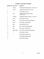
Wiring Descriptions
Digital Controller Terminals
Terminal
Wire Color
Description
1
Red
RTD input
2
Red
RTD input
3
Orange
Voltage output to seconc
system (1.2 volts (+) dc).
Blue
Voltage output to secondary circuit for heater
system (1.2 volts (-) dc).
Not Used
(2) Red
Voltage output to secondary board and alarm
(6 volts (+) dc).
Brown
Incoming power supply from circuit board.
Blue
Incoming power supply from circuit board.
12
1-360038/E
Secondary Circuit Board Terminals
Terminal (Tl) Wire Color
Description
1
Orange
Voltage input for heater system (1.2 volts (+) dc).
2
Yellow
Voltage output to alarm (6 volts (-) dc).
3
—
This terminal is not used.
4
Red
Voltage input for alarm delay system
5
Dark blue
6
Brown
7
Brown
(6 volts (+) dc).
Voltage input for heater system (1.2 volts (-) dc).
Power input from switch.
Power output to chart recorder transformer.
8
Brown
Power output to controller (#7).
9
Blue
Power input from switch.
10
Blue
Power to chart recorder transformer.
11
Blue
12
Black or F
Black or Red
—
Power output to controller (#8).
13
Power output to chamber heater thermostat.
This terminal is not used.
14
Central Alarm (normally open).
15
Central Alarm (normally closed).
16
Central Alarm (common).
13
1-3 6003 8/E
Terminal (T2) Wire Color
Description
Al
Brown
Main power input to unit and power failure alarm.
A2
Brown
Main power to power switch.
Bl
Blue
Main power input to unit and power failure alarm.
B2
Blue
Main power to power switch.
Terminal (T3) Wire Color
Description
1
Black
Power to Heater.
2
Black
Power to compressor.
3
Brown
Brown
Power to Interior fan.
Power to Interior Outlet.
4
Blue
Power to Interior Fan.
5
Blue
Power to Interior Outlet.
Black w/stripe
Power to compressor.
14
1-360038/E
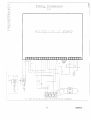
Component List for Schematic
Component
Location
Access
A - Audible alarm
Front control panel
Remove control panel
B - Alarm delay switch (NC)
Front control panel
Remove control panel
C - Main power switch
Front control panel
Remove control panel
D - Chart recorder
Top front panel
Open chart panel
E - Chamber fan
Inside chamber
(behind back wall)
Remove chamber back wall
F - Chamber heater
Inside chamber
(behind back wall)
Remove chamber back wall
G - Compressor and
Condensor fan
Top of unit
Remove top panel
H-RTD
Top of chamber
Remove front panel
I - Temperature controller
Front control panel
Remove control panel
J - Secondary circuit board
Top of unit (inside)
Remove control panel
L - Chamber outlet
Inside chamber
(right side wall)
Remove back panel
M - Audible alarm switch
Top front panel
Remove control panel
N - Thermostat Switch
Inside chamber
(back wall)
Remove chamber back wall
T2 - Chart transformer
Top of unit (inside)
Remove front panel
Components on secondary circuit board
PI - Alarm Timer Adjustment
See secondary circuit board above
1-360038/E
Troubleshooting
(PC 100)
***Electrical***
Problem
Unit does not turn on.
Controller does not turn
on.
Platelet agitator not
operating.
Power cord on agitator
rubbing.
Chamber fan not
operating.
Possible Cause
Action to be Taken
- Circuit breaker or fuse
activated.
- Reset circuit breaker or replace fuse.
- Faulty outlet connection.
- Verify outlet is good. Plug into a
different outlet.
- Faulty power cord.
- Verify proper cord connections.
Change power cord.
- Faulty power switch.
- Replace switch.
- Faulty connections.
- Verify connections from the power
switch to the controller.
- Faulty controller.
- Verify voltage to the controller. If
receiving voltage and not operating,
replace controller.
- Faulty platelet agitator.
- Verify that agitator is working
properly.
- Faulty power outlet.
- Verify voltage to outlet. If no
voltage, check connections to and
within the outlet.
- Agitator not centered in
chamber.
- Verify positioning of agitator.
- Power cord not
positioned properly.
- Verify positioning of cord.
- No power to fan.
- Verify power to the fans. If no
voltage check connections.
- Faulty fan.
- Replace fan.
16
1 -36003 8/E
Compressor not running
- Compressor not getting
power.
- Visually verify that condenser fan is
operating. If fan is operating see the
next step. If not, check for faulty
connection.
- Compressor failure.
- Replace compressor.
- Compressor in thermal
shutdown.
- Verify that the compressor unit is
getting proper airflow - at least 4
inches from any obstacles. Make
sure the condenser grill is clean.
Turn power off and allow
compressor to cool down. Turn unit
back on and verify whether
compressor is operating. If the
compressor fails to operate either the
compressor thermal switch could be
faulty or the compressor itself could
be faulty.
17
1-360038/E
***Alarms and Controller***
Audible alarm not
sounding.
Not waiting for alarm
delay to cycle.
- The alarm system has a delay system
before the audible alarm will sound.
Wait sufficient time for alarm delay
to cycle.
Verify Alarm and
Controller settings.
- The controller alarm value or other
values may have been altered
causing the non-alarm condition.
Refer to the proper controller value
settings and change accordingly.
- Faulty controller.
Faulty secondary circuit
board.
Alarm sounding
sporadically.
• Refer to the Alarm System Test
portion of this manual. If the alarm
light on the controller is not
illuminating, replace the controller.
If the controller alarm light is
operating, verify voltage to inputs 4
and 6 on the secondary circuit board.
If receiving voltage, proceed to next
step.
• After waiting for alarm delay period,
if no voltage is going to the alarm,
then replace the secondary circuit
board.
Faulty connections.
Verify proper line connections.
Faulty alarm
Replace alarm.
Faulty alarm system.
Verify proper operation of the
controller, secondary circuit board
and line connections.
Alarm deviation value set
too tight.
During normal operation the
temperature will fluctuate as a result
of many factors. If the alarm value
is set too tight to the operating value
the alarm may sound often. The
alarm system is to warn of serious
unit temperature fluctuations.
Increase the alarm value.
Door not closing.
Verify proper alignment of door
closure.
Verify door gaskets are sealing
properly.
Air gaps around door.
1-360038/E
Chamber temperature not
stabilizing.
• Verify that the chamber temperature
is maintaining a proper and
consistent temperature. Refer to
Quality Control section.
Alarm not activating at
proper temperature.
- Calibrate controller.
Refer to section on Calibration of the
Digital Controller.
Controller setting not
calibrated properly.
- Calibrate controller.
Refer to section on Calibration of the
Digital Controller.
Central alarm not
operating.
- Faulty connections.
Verify proper connections to
incubator and within the central
alarm system.
Alarm output relay is
faulty.
- Faulty controller.
Faulty secondary circuit
board.
19
Verify that you have the proper relay
for your central alarm system and
that it is connected properly (refer to
the section on central alarm hookup). Verify that the relay is
operating. If not, replace the faulty
relay.
Verify that the controller alarm
system is operating correctly. If not,
replace the controller.
Verify that there is voltage output to
the alarm. If not, replace the
secondary circuit board.
1-3 6003 8/E
*** Chamber Temperature
Chamber temperature
not cooling.
Chamber temperature
not heating.
"k"k-k
- Low refrigerant pressure.
- Verify proper refrigerant level in
compressor unit.
- Faulty compressor.
- Verify connections. Change
compressor unit.
- Faulty controller.
- If heater light is always illuminated
even when the chamber temperature
is above the set value, controller is
not operating correctly. Verify
correct controller input values. If
correct, then replace the controller.
Faulty secondary circuit
board.
- Current should only be going to
heater when controller heater light is
on. If current is going to the heater
all the time from the secondary
circuit board (line 12), then change
secondary circuit board.
Door not sealing tight.
- Verify that door is closing and
sealing properly.
Faulty controller.
- Verify that controller heater light is
illuminating to operate heater.
Verify voltage going into
connections 1 and 5 on the
secondary circuit board when the
heater light is illuminated. If no
voltage, change controller.
- Faulty thermostat
- Verify that the heater thermostat is
functioning properly. It should be
closed when the chamber temperature
is within normal operating limits. If it
is not closed then replace thermostat.
Faulty secondary circuit
board.
- Faulty heater.
- Current should be coming out of line
12 on the secondary circuit board to
the heater when the controller heater
light is on. If not, change secondary
circuit board. If yes, check
connections to the heater.
- Replace heater.
20
1-360038/E
***Other***
Ice lying in water tray.
Severe water puddling in
water tray.
- Refrigerant pressure is
low.
- Verify refrigerant pressures. Add
- Drain hole plugged.
- Unclog drain hole.
- Door not closing tight,
allowing humid air into
the chamber.
Water is puddling outside - Drain pan leaks.
of the incubator.
- Water is condensing on
evaporator lines to the
compressor.
Platelets are "pooling" to
one side of the bag.
refrigerant as needed.
Verify that door gasket is sealing and
door is closing properly.
• Seal any leaks in drain pan with
silicone.
• Apply additional cork tape to copper
lines.
- Excessive humidity.
Water will accumulate more during
humid periods. Make sure door is
closing properly.
- Unit not level.
Verify that the unit is sitting level.
Verify that the agitator is sitting
level.
21
1-360038/E
EL/TIE^
CHART RECORDER
OPERATION & TROUBLESHOOTING
Section 1 - Operation
1) Temperature calibration: If the temperature marked by the chart recorder does not match that
of the chamber (once stabilized at setpoint), adjustment is possible using the left and right arrow
keys (see figure 1). These must be pressed and held down for five seconds to initiate stylus
movement. Continue to hold down until stylus has moved to the correct temperature. If neither
button is pressed for 5 seconds the new offset will take effect and the recorder will return to
normal operation.
2) Changing the chart paper: Press and hold the "C" button. When the stylus begins to move
toward the left, release the button. Wait until the stylus has moved to the edge of the chart then
remove the old chart paper. Position the paper so that the correct time line coincides with the time
line groove (see fig 1). Re-attach the chart knob and screw it securely against the chart.
CAUTION: When stylus is in change pressing the Left or Right arrow buttons will change
the chart recorder temperature range. See section 1.5 for setting the chart
ranges.
Press and hold the "C" button again until the stylus begins to move to the right, then release.
Check to make sure that the stylus is marking on the chart paper. If not, refer to Section 2:
troubleshooting.
3) Battery Backup: Install a 9 volt battery as shown in figure 1 and connect the lead. This battery
allows the recorder to continue to function normally for approximately two hours in the event of a
power failure. The light on the face of the chart recorder remains a constant green color
indicating the battery is good. If the battery becomes weak and needs to be replaced, the light
will begin flashing.
Right Arrow
Battery Connection
Left Arrow
Chart Change
Time Line Groove
Stylus
Chart Knob
Figure 1
15425 Herriman Blvd, Noblesville, IN 46060
PHONE (317) 773-9073 FAX (317) 773-9082
USA & CAN: 1-800-743-5637
www.helmerinc.com
360076-1/C
4) Procedure to run test pattern (to verify operation of motors and electronics)
a) Press and hold chart change and right arrow buttons simultaneously for about 5 seconds until
the LED goes out.
b) The recorder will proceed through a test consisting of stepped patterns through the
temperature range, which will end once the pattern has completed one rotation. The test may
be terminated at any time by pressing any button for about one second.
c) After testing, the chart recorder will automatically return to normal operation and the LED
will turn back on.
5) Chart Range: The Helmer chart recorder supports three temperature ranges:
Range 1
Range 2
Range 3
0 to 35°C (Platelet Incubator Products)
-5 to 20°C (Helmer Refrigerator Products)
-50 to 0°C (Helmer Freezer Products)
LED Single Flash
LED Double Flash
LED Triple Flash
To determine current chart range, press and hold change paper button until stylus begins moving
toward the edge of the chart. The LED will flash out the currently selected chart range 1, 2 or 3.
The chart range may be changed by pressing the RIGHT or LEFT buttons, increasing or
decreasing the range value, respectively. The LED will flash out the currently selected range. To
save new range setting press and hold change chart button again until stylus begins moving
toward temperature range.
360076-110
Section 2 - Trouble Shooting
1) Chart recorder paper not moving:
a) Chart knob not tightened on paper: Tighten the chart knob.
b) Ribbon cable at P2 is either not connected or reversed with P3.
c) No power to the recorder: Check for line voltage supply to the chart recorder
transformer. Check for 13VAC from the transformer to the chart recorder. (See
product service manual for location of chart recorder transformer).
2) Stylus exceeds outer edge of paper: Home Stop Post Bent.
If the home stop post, which is located on the bottom of the circuit board, is bent the stylus will
travel off the paper. Verify that it is straight and that the stylus bracket makes contact with the
post during start up.
3) Chart stylus off scale and will not adjust back to center: JP1 is in probe simulation position
(over both pins). Move JP1 to one pin.
4) LED continuously blinks:
a) Battery is either low or not hooked up. Measure battery and check connection.
b) RTD probe defective. Move JP1 to probe simulation position (over both pins) if chart returns
to normal operation replace probe. Make sure to return JP1 to one pin after probe is replaced.
c) Chart is in paper change mode, as indicated by a repeated sequence of flashes. Press and hold
"C" button for about 2 seconds.
5) Chart stylus not marking on paper: Stylus is bent away from paper.
Gently bend stylus until it touches paper. If it is still not marking, remove the stylus arm by
loosening the two stylus arm mounting screws, bend the bracket, replace and retighten screws.
Note: when refastening the stylus arm, ensure it is positioned in line with the time line groove in
figure 2.
6) After changing paper with the "C" button, the stylus does not return to the proper
temperature: When the stylus was in the change paper position, the Left or Right button was
accidentally pressed changing the chart temperature range. Refer to section 1.5 for setting the
temperature range.
360076-1/C