1
TM-311
1st Printing
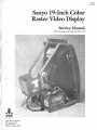
Sanyo 19-Inch Color
Raster Video Display
Service Manual
With Schematic and illustrated Parts List
JI~
ATARf
G A M E S
Atari Games Corporation
675 Sycamore Drive
P.O. Box 361110
Milpitas, California 95035
© 1987 by Atari Games Corporation
All rights reserved
No part of this publication may be reproduced by any mechanical, photographic, or electronic
process, or in the form of a phonographic recording, nor may it be stored in a retrieval system,
transmitted, or otherwise copied for public or private use, without permission from the publisher.
The game play, all graphic designs, this manual, the game operators manual, and its accompanying schematic diagrams are protected by the U.S. Copyright Act ofl976.
This Act provides for increased penalties for violating federal copyright laws. Courts can impound
infringing articles while legal action is pending. Ifinfringers are convicted, courts can order destructUm of the infringing articles.
In addition, the Act provides for payment of statutory damages of up to $250,000 in certain
cases. Infringers may also have to pay costs and attorneys' fees and face an imprisonment of up
to five years.
Atari Games Corporation will aggressively enforce its copyrights against any infringers. Uf will
use all kgal means to immediately halt any manufacture, distribution, or operation of a copy of
video games made by us. Anyone who purchases such copies risks forfeiting such a game.
Published by:
Atari Games Corporation
675 Sycamore Drive
P.O. Box 361110
Milpitas, California 95035
Printed in the U.S.A.
9R
Table of Contents
I
Warnings and Cautions
Introduction . . . . . . . . . . . . . . . . . . . . . . . . . . . . . . . . . . . . . . . . . . . . . . . . . . . . . . .
Before You Start . . . . . . . . . . . . . . . . . . . . . . . . . . . . . . . . . . . . . . . . . . . . . . . . . . . .
Safety Measures . . . . . . . . . . . . . . . . . . . . . . . . . . . . . . . . . . . . . . . . . . . . . . . . . . . .
Cathode-Ray Tube Handling . . . . . . . . . . . . . . . . . . . . . . . . . . . . . . . . . . . . . . . . . .
Replace with Proper Components . . . . . . . . . . . . . . . . . . . . . . . . . . . . . . . . . . . . . .
Final Testing Before Reinstalling Display . . . . . . . . . . . . . . . . . . . . . . . . . . . . . . . . . .
2
Specifications
Power Input and Consumption . . . . . . . . . . . . . . . . . . . . . . . . . . . . . . . . . . . . . . . .
Temperature and Humidity . . . . . . . . . . . . . . . . . . . . . . . . . . . . . . . . . . . . . . . . . . .
Current and Voltages . . . . . . . . . . . . . . . . . . . . . . . . . . . . . . . . . . . . . . . . . . . . . . . .
CR'.f Specifications . . . . . . . . . . . . . . . . . . . . . . . . . . . . . . . . . . . . . . . . . . . . . . . . . .
Connectors . . . . . . . . . . . . . . . . . . . . . . . . . . . . . . . . . . . . . . . . . . . . . . . . . . . . . . . .
Pattern Size . . . . . . . . . . . . . . . . . . . . . . . . . . . . . . . . . . . . . . . . . . . . . . . . . . . . . . . .
3
RGB Signals . . . . . . . . . . . . . . . . . . . . . . . . . . . . . . . . . . . . . . . . . . . . . . . . . . . . . . .
6
4
4
6
6
6
6
6
6
6
7
Repair
Cathode-Ray Tube Replacement. . . . . . . . . . . . . . . . . . . . . . . . . . . . . . . . . . . . . . . .
Yoke Replacement . . . . . . . . . . . . . . . . . . . . . . . . . . . . . . . . . . . . . . . . . . . . . . . . . .
Horizontal-Output Transformer Replacement . . . . . . . . . . . . . . . . . . . . . . . . . . . . .
J
3
3
3
Signal Test Points
Sync Signal . . . . . . . . . . . . . . . . . . . . . . . . . . . . . . . . . . . . . . . . . . . . . . . . . . . . . . . .
5
3
3
3
Control Adjustments
Brightness. . . . . . . . . . . . . . . . . . . . . . . . . . . . . . . . . . . . . . . . . . . . . . . . . . . . . . . . .
Tracking. . ...................... . ............... . ... . .............
Horizontal Centering . ...............................................
Vertical Hold . . . . . . . . . . . . . . . . . . . . . . . . . . . . . . . . . . . . . . . . . . . . . . . . . . . . . .
Vertical Size . . . . . . . . . . . . . . . . . . . . . . . . . . . . . . . . . . . . . . . . . . . . . . . . . . . . . . .
Horizontal Width. . . . . . . . . . . . . . . . . . . . . . . . . . . . . . . . . . . . . . . . . . . . . . . . . . .
Focus . . . . . . . . . . . . . . . . . .. . . . . . . . . . . . . . . . . . . . . . . . . . . . . . . . . . . . . . . . . . .
Horizontal Hold . . . . . . . . . . . . . . . . . . . . . . . . . . . . . . . . . . . . . . . . . . . . . . . . . . .
4
1
1
1
2
2
3
7
7
8
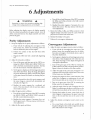
Adjustments
Purity Adjustments . . . . . . . . . . . . . . . . . . . . . . . . . . . . . . . . . . . . . . . . . . . . . . . . .
Convergence Adjustments . . . . . . . . . . . . . . . . . . . . . . . . . . . . . . . . . . . . . . . . . . . .
B+ Adjustment . . . . . . . . . . . . . . . . . . . . . . . . . . . . . . . . . . . . . . . . . . . . . . . . . . . .
9
9
10
Sanyo Video Display Parts List. . . . . . . . . . . . . . . . . . . . . . . . . . . .
11
List of IDustrations
Figure 1
Figure 2
Figure 3
Figure 4
Figure 5
Figure 6
Figure 7
Figure 8
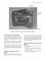
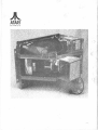
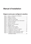
Overview of Sanyo 19-Inch Color Raster Display............ ... . . .
Display Pattern Sizes . . . . . . . . . . . . . . . . . . . . . . . . . . . . . . . . . . . . . . .
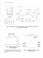
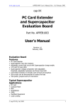
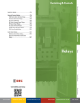
Adjustable Controls and Test Points on Main Chassis PCB, Control
PCB, and Signal Inversion PCB . . . . . . . . . . . . . . . . . . . . . . . . . . . . . . .
Blanking Pulse Waveform of Video Amplifiers . . . . . . . . . . . . . . . . . . . .
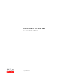
Adjustable Controls on Picture Tube Socket PCB . . . . . . . . . . . . . . . . .
Purity and Convergence Adjustments . . . . . . . . . . . . . . . . . . . . . . . . . .
Sanyo Model 20-EZV Video Display Schematic Diagram . . . . . . . . . . .
Sanyo Model 20-Z2AW Video Display Schematic Diagram . . . . . . . . . .
2
4
5
5
5
10
16
20
Sanyo 19" Standard-Resolution Display
I Warnings and Cautions
Introduction
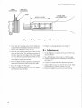
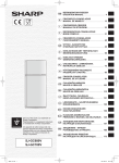
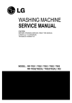
This display is contained within a separate chassis inside the
game cabinet. The Main Chassis printed-circuit board (PCB)
is mounted to the display chassis under the video tube, the
Control PCB is located next to the Main Chassis PCB, and
the Picture Tube Socket PCB is attached to the neck pins of
the video tube. Input signals for the display are suµglied
through a 6-pin harness connector to the Signal Inversion
PCB, then from that board to the Main Chassis PCB. (See
Figure 1.)
)
Before You Start
Never attempt to work on a display until you are familiar
with servicing precautions and procedures necessary for
high-voltage equipment. Remember, any video display has
three sources of possible danger:
A
WARNING
A
High Voltage
This display cont.ains high voltages capable of delivering
lethal quantities of energy. To avoid danger, do not attempt to service the chassis until you have observed all
precautions necessary for working on high-voltage
equipment.
X-Radiation
This chassis has been designed for minimum X-radiation
hazard. However, to avoid possible exposure to soft Xradiation, it is imperative that you never modify the
high-voltage circuitry.
Implosion Hazard
If you drop the display and the picture tube breaks, it
will implode! Shattered glass and the yoke can fly 6 feet
or more from the implosion. Use care when replacing
any display.
• Strong electric shock, due to high voltage or AC line
voltage
• X-ray radiation
• Implosion
Therefore, never modify any circuit in this display.
Do not service this video display until you are thoroughly
familiar with all warnings and safety measures given in this
chapter.
(
,/
Safety Measures
Good safety habits will allow you to automatically take the
proper precautions, even if you are rushed. Whenever you
work on a display, always ground the chassis first. Also, use
only one hand. This avoids the possibility of carelessly putting one hand on the chassis or ground and the other on an
electrical connection. Doing so could cause a severe electrical
shock.
Ifyou service the Sanyo Color Raster Display on a test bench,
use only the power supply that came with the game or a 100
VAC isolation transformer. (Refer to the parts list in the game
manual for the Atari part number of the power supply assembly.) Do not use line voltage because the voltage produced by this source will damage this display.
To prevent fire or shock hazard, never expose this display to
moisture.
Periodically check for frayed insulation on the wires within
the display. If frayed wires are found, replace them with the
same gauge and length of wire. Always observe the original
lead dress (routing and length of harness wires).
Use extra precaution in the high-voltage circuitry areas of the
display. Ifa short circuit occurs, replace any components that
indicate they may have overheated.
Sanyo 19" Standard-Resolution Display
Main Chassis PCB
Figure I Overview of Sanyo 19-Inch Color Raster Display
Cathode-Ray Tube Handling
Wear safety goggles and heavy gloves for protection whenever you handle a cathode-ray tube (CRT). Keep other people away if they are not wearing safety goggles. Never lift the
CRT by the neck; the neck should only be used to guide the
lifting process.
Use extreme care when handling the CRT. Rough handling
may cause the CRT tube to implode. Do not nick or scratch
the glass or subject any undue pressure upon the tube at any
time.
If servicing the CRT, first discharge the high voltage on the
anode connection to chassis ground-not to the cabinet or
other mounting parts. See Chapter 5, step 3 of the CathodeRay Tube Replacement procedure to discharge the high voltage.
Replace with Proper Components
Maintain the specified values of all components within the
display. Failure to do so could cause a rise in the high voltage.
2
The cathode-ray tube of this display employs integral implosion protection. For continued safety, replace it only with a
tube of the same type number. Refer to the parts lists in
Chapter 7 of this manual. For continued product safety,
use only exact replacement parts, especially for those
parts identified in the parts lists with the A symbol and on
the schematics with shading.
Final Testing Before Reinstalling
Display
Before reinstalling this color display into the game, you must
check the following:
1. Inspect all harness wiring within the display area. Be sure
no wires or cables are pinched between the cabinet and
other parts in the display.
2. Replace all protective devices such as insulating fish paper,
compartment covers, and shields.
Sanyo 19" Standard-Resolution Display
2 Specifications
Power Input and Consumption
Line Voltage
100 VAC, within + 10% and
-15%
Line Frequency
47to 63 Hz
Power Consumption
74 Wmaximum
Temperature and Humidity
Ambient Air Temperature:
Operating
0°C to +55°C ( +32°F to
+130°F)
Non-operating
-40°C to +65°C (-40°F to
+149°F)
Humidity
10% to 90%, non-condensing
Current and Voltages
CRT Anode Current
(Average)
Less than 650 µA
High Voltage
24kV ±1.5 kV
CRT Specifications
;
Convergence Tolerance:
At Screen Center
0.010 inch (0.25 mm) maximum
misconvergence
At Screen Edges
0.020 inch (0.5 mm) maximum
misconvergence
Color Purity
Practically uniform throughout
the scree~ area after degaussing
with a hand-held degaussing coil.
Scan Rates:
Horizontal
15.75 kHz, within ±500 Hz
Vertical
60 Hz, within ±5 Hz
CRT Type
5JOUTB22, 19-inch,90°
Tilt of Deflection Yoke
Declination of a horizontal line is
within 0.10 inch (2.54 mm) .
Connectors
6-Pin Connector for Video Signals:
Pin 1
Green
Pin 2
Red
Pin 3
Blue
Pin 4
Ground
Pin 5
Ground
Pin 6
Negative Composite Sync
3-Pin Connector for Power:
Pin 1
100 VAC
Pin 2
No Connection
Pin 3
Neutral
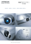
Pattern Size
You should be able to reproduce the patterns as shown in
Figure 2.
3
Sanyo 19" Standard-Resolution Display
Maximum Size
Minimum Size
Figure 2 Display Pattern Sizes
3 Control Adjustments
A
WARNING
A
Remember to observe the precautions regarding high
voltages when making adjustments to this display!
NOTE
Before making any of the following adjustments, turn
on the display and allow it to warm up for at least 5
minutes.
Brightness
The BRIGHT control VR351 should be adjusted if the picture image is either too bright or too dark. See Figure 3 for
the location of the Brightness control on the Control
Printed-Circuit Board (PCB).
NOTE
Too high a brightness level will cause the retrace lines to
show; too low a level will cause the entire screen to be
dark and obscure.
3. If the proper level of brightness cannot be obtained by
adjusting the Brightness control, adjust the SUBBRIGHT control VR301 as follows:
a. Set the game to display the self-test diagnostic pattern
showing a white crosshatch. (Refer to the Self-Test
chapter in the game manual for details on selecting
this pattern.)
b. Attach an oscilloscope probe to each collector of the
video amplifiers TR251, TR252, and TR253 and observe the blanking pulse waveform of each amplifier.
The one with the most deflection of the blanking
pulse is the lead gun.
c. Adjust the Sub-Brightness control so that the waveform is similar to the one shown in Figure 4.
1. Place the game in the attract or play mode.
Tracking
2. Using the Brightness control, adjust the display for a
pleasing level of brightness.
The Screen, Brightness, the three Bias, and two Drive controls should be adjusted ifthe picture image is not the correct
4
Sanyo 19" Standard-Resolution Display
MAIN PWB
INVERT~
aJ
~
OUT~
0....
z
0
Ui
a::
w
NON INVERT
z
OUT
>
ru;
o
~
4A
125V
SERVICE
VR101 VR102 VR103
~ ~ ~ ~
G
~~
B
R
TP91
OBJ
JooooooJ
SIGNAL INPUT
SW301
H SIZE
F301
H
CENT
V
HOLD
D
@
VR451
IC401
TR4~
-=-i
aJ
BRIGHT
H HOLD
TR402
i@:
R609
rr=IJ
VR355 VR351 VR352 VR353 VR354
INPUT
VR301
--;)
CONTROL PWB
VOL
~
0.3A 125V
®
L453
w
111
SIGNAL
SUB-BRIGHTNESS
F302
0
_J
~
~
V POS
@?J
VR403
UP
~v
CENT
HORZ
OUTPUT
0902
~
T452
FBT
ONO JUMPER
V
SIZE
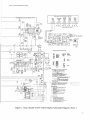
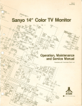
Figure 3 Adjustable Controls and Test Points on Main Chassis PCB, Control PCB,
and Signal Inversion PCB
Blanking Pulses
Picture Tube
Socket PCB
140V DC
A-Drive
VR254
Figure 4 Blanking Pulse Waveform
of Video Amplifiers
color or brightness, and whenever the purity and convergence is adjusted. (See Figure 3 for the location of the Screen
and Brightness controls and Figure 5 for the Bias and Drive
controls.)
B-Drive
VR255
G-Bias
VR253
ri
I
I
1--
r
,- -
I
A-Bias
'VR 251
r,
I II I
I ,--
B-Bias
VR252
Figure 5 Adjustable Controls on Picture
Tube Socket PCB
5
Sanyo 19" Standard-Resolution Display
l. &move power from both the game and the display.
2. Unplug the 6-pin video-signal connector, which is
wired to the Signal Inversion PCB.
3. Set the R-DRIVE control VR254 and the B-DRIVE
control VR255 to their mechanical centers.
4. Set all three BIAS controls VR251, VR252, and VR253
to their mechanical centers.
5. Set the Brightness control to its mechanical center and
the Screen control fully counterclockwise.
6. Ifthe game has a self-test diagnostic pattern for the color
purity test, set the game to display this test to complete
the white tracking procedure. If the game does not have
a color purity test, an RGB signal generator capable of
producing a gray and a white raster is necessary.
7. &connect the 6-pin video-signal connector and apply
power to the display.
8. Set the game to display the self-test diagnostic pattern
showing the gray raster.
9. Slowly adjust the Screen control until the CRT screen
displays the first hint of color. Do not adjust the Bias.
control for the color that first appeared on the screen.
Instead, slowly adjust the Bias controls for the other
two colors until the screen displays a faint gray color.
10. Set the game to display the self-test diagnostic pattern
showing the white raster, and adjust the R-Drive and BDrive controls for a uniform white. (Note: repeat steps
8 and 9 so that both the gray and white rasters have
uniform color.)
11. &tum the game to the attract mode. Ifnecessary, adjust
the Brightness control if the screen appears to be too
dark or too bright.
location ofV-HOLD control VR353 on the Control PCB.
Tum this control until the picture no longer drifts up or
down on the screen.
Vertical Size
The Vertical Size control should be adjusted if the screen
image is either not filling the screen vertically, or if it is overscanning the screen vertically. Figure 3 shows the location
ofV-SIZE control VR354 on the Control PCB.
1. Set the game for the diagnostic test that displays the convergence grid and dots.
2. Adjust V-SIZE control until the top and bottom grid
lines are along the top and bottom edges of the screen.
These grid lines should not disappear off the edges of the
screen, which would indicate overscanning.
Horizontal Width
The Horizontal Width coil should be adjusted if the screen
image is either too wide or narrow. Figure 3 shows the location ofHORIZ WIDTH coil IA53 on the Main Chassis
PCB.
1. Set the game for the diagnostic test that displays the convergence grid and dots.
2. Use only a non-metallic Allen wrench (commonly called
a "tweaking tool") to adjust the Horizontal Width coil
until the right and left grid lines run along the edges of
the screen. These grid lines should not disappear off the
edges of the screen, which would indicate overscanning.
Focus
Horizontal Centering
The Horizontal Centering control should be adjusted if the
picture is not centered on the screen, as indicated by a black
area at either the left or the right edge. Figure 3 shows the
location of the H-CENT control VR352 on the Control
PCB. Adjust this control until a normal screen image is obtained.
Vertical Hold
The Vertical Hold control should be adjusted if the picture
drifts straight up or down on the screen. Figure 3 shows the
6
The Focus control should be adjusted if the screen image is
not sanyoly defined. The Focus control is attached to the
top of the horizontal-output transformer as shown in Figure
3. Tum this control until you get optimum screen sanyoness.
Horizontal Hold
The Horizontal Hold control should be adjusted if the picture is drifting sideways across the screen. Figure 3 shows the
location ofH-HOLD control VR451 on the Main Chassis
PCB. Adjust this control until the black lines no longer slant
downward or upward and you get a normal screen image.
Sanyo 19" Standard-Resolution Display
4 Signal Test Points
RGBSignals
Sync Signal
The red, green, and blue signals can be checked at the collectors ofTR251 (Red), TR253 (Green), and TR252 (Blue).
These transistors are located on the Picture Tube Socket
PCB.
The negative composite synchronization (Sync) signal can
be checked at pin 6 of the 6-pin video-signal connector,
which is located off of the Signal Inversion PCB. Do not jam
a test probe into the connector pin, because this may cause
the pin to stretch and fall out of the connector housing.
5Repair
WARNING
Before removing or installing any component of this display, always disconnect the power source! Observe the
precautions regarding high voltages and cathode-ray
tube handling when servicing this display.
6. Unplug the 4-wire connector attaching the yoke wires
to the Main Chassis PCB.
7. Unhook the spring that holds the braided ground wire
(located near the bottom comer of the CRT).
8. Use a o/i 6 -inch hex socket wrench to remove the four
screws holding the CRT to the steel frame.
9. CAREFULLY remove the CRT by easing it out the
front of the chassis.
NOTE
The tools required to replace these assemblies include:
5/16-inch hex socket wrench, Phillips screwdriver, and a
soldering iron.
10. Place the CRT on a soft mat in a protected location .
11. Install a CRT in the reverse order of removal. Then adjust the SCREEN control G2 as follows:
a. Apply power to the display.
Cathode-Ray Tube Replacement
b. Tum the Brightness control on the Control PCB to
the fully counterclockwise position.
1. Disconnect the 6-pin video-signal connector located off
the Main Chassis PCB.
c. Adjust the Screen control for a dimly-lighted screen.
This control is attached to the horizontal-output
transformer as shown in Figure 3.
2. Remove the display assembly from the cabinet as described in the game manual.
d. Readjust the Brightness control as described in
Chapter 3.
3. Discharge the high voltage from the cathode-ray tube
(CRT) as follows:
a. Attach one end of a well-insulated, 20 kV-resistive
jumper to ground.
b. Briefly touch the free end of the resistive jumper to
the anode by sliding it under the anode cap.
c. Wait two minutes.
Yoke Replacement
NOTE
You must reconverge the picture whenever the yoke is
replaced.
d. Discharge the anode again.
e. OirefUlly remove the large high-voltage anode connector from the cathode-ray tube.
1. Disconnect the 6-pin video-signal connector located off
the Signal Inversion PCB.
4. Unplug the Picture Tube Socket PCB from the rear of
the tube.
2. Remove the display assembly from the cabinet as described in the game manual.
5. Unplug the degaussing coil 2-pin connector from the
Main Chassis PCB.
3. Discharge the high voltage from the CRT as described in
step 3 of Oithode-Ray Tube Replacement.
7
Sanyo 19" Standard-Resolution Display
4. Unplug the Picture Tube Socket PCB from the rear of
the CRT.
3. Discharge the .high voltage from the CRT as described
in step ·3 of Cathode-Ray Tube &placement.
5. Use a thin knife or a single-edged razor blade and carefully loosen the three rubber wedges from the CRT surface.
4. Open the anode holder and remove the anode lead.
6. Loosen the Phillips-head screws used to tighten the two
neck clamps around the neck of the CRT.
5. Unplug the Picture Tube Socket PCB at the rear of the
CRT. Then unsolder the white wire on the Main Chassis PCB (goes to AO) and white wire (goes into the
socket) on the Picture Tube Socket PCB.
7. Slide the magnet assembly and the yoke assembly off the
end of the CRT.
6. Remove the Phillips-head screws that secure the metal
cover over the transformer.
8. Replace the yoke assembly in the reverse order of removal.
7. Remove the Phillips-head screw holding the metal
bracket to the right side of the transformer.
Horizontal-Output Transformer
Replacement
1. Disconnect the 6-pin video-signal connector located off
the Main Chassis PCB.
2. Remove the display assembly from the cabinet as described in the game manual.
8
8. Unsolder the 11 transformer connections on the bottom side of the Main Chassis PCB.
9. Lift the transformer off the Main Chassis PCB.
10. Replace the transformer in the reverse order of removal.
Be sure to check the picture for sanyoness. If appropriate, readjust the Focus control as described in Chapter
3.
Sanyo 19" Standard-Resolution Display
6 Adjustments
A
WARNING
A
Remember to observe the precautions regarding high
voltages when making adjustments on this display!
Before adjusting the display, remove the display assembly
from the cabinet as described in the game manual. Leave all
cables connected between the display assembly and other
parts of the game.
Purity Adjustments
1. Set up the display for the purity adjustments as follows:
a. If you will also be adjusting the convergence of the
outer screen area, loosen the mounting screws for
both the deflection yoke and the magnet.
b. Position the cabinet so that the CRT faces either
north or south.
c. Degauss the CRT tube with a hand-held degaussing
coil.
2. Adjust for red purity as follows:
a. Tum off the green and blue guns of the CRT by rotating the G-BIAS VR253 and B-BIAS VR252 c~n
trols to the fully counterclockwise position. (See Figure 5 for the location of the Bias adjustments.)
b. Set the game to display any self-test diagnostic pattern
that shows solid white. Keep this image throughout
the purity adjustments. (Refe~ to the Self~Test c~apter
in the game manual for details on selectmg this pattern.)
c. Rotate and spread the tabs of the purity magnets until
the screen image is centered both horizontally and
vertically. (See Figure 6.)
d. Readjust the purity magnets for a uniformly red
screen. This may interact with the previous adjustment made in step 2c.
3. Adjust for green purity as follows:
a. Tum off the red and blue guns of the CRT by rotating
the R-Bias and G-Bias controls to the fully counterclockwise position.
b. Readjust the purity magnets, if necessary, for a uniformly blue screen. This may interact with the previous adjustments.
5. Return the R-Bias, G-Bias, and B-Bias controls to their
original settings. Check the screen for a pure white display that is not tinted with other hues.
6. Reinstall the display in the game.
7. Perform the convergence adjustments.
Convergence Adjustments
1. Adjust for static convergence (screen center) as follows:
a. If you will also be converging the outer area of the
picture, loosen the mounting screws for the deflection yoke and magnet, if not already done as part of
the purity adjustments.
b. Set the game to display the self-test diagnostic pattern
that shows a black background with white lines and
dots. Keep this image on the display throughout all
convergence adjustments.
c. Tum off the green gun of the CRT by rotating the
G-Bias control to the fully counterclockwise position.
Figure 4 shows the location of the Bias controls.
d. Adjust the angle of the center pair of magnets to superimpose the red and blue vertical lines in the center
of the screen area. (See Figure 5.)
e. Keeping their angles the same, rotate both tabs of the
center pair of magnets to superimpose the red and
blue horizontal lines in the center of the screen area.
f. Tum on the green gun of the CRT by returning the
G-Bias control to its original setting.
g. Adjust the angle of the rear pair of magnets shown in
Figure 5 to superimpose the green vertical lines on the
red and blue ones already in the center of the screen.
a. Tum off the red and blue guns of the CRT by rotating
the R-BIAS VR251 and B-BIAS VR252 controls to
the fully counterclockwise position.
h. Keeping their angles the same, rotate both ~abs of
these magnets to superimpose the green honzontal
lines on the red and blue ones in the center of the
screen.
b. Readjust the purity magnets, if necessary, for a uniformly green screen. This may interact with the previous adjustment.
2. Adjust the dynamic convergence (outer screen) as follows:
4. Adjust for blue purity as follows:
a. Use a razor blade or thin knife and carefully loosen
the glue holding the three rnbber wedges beneath the
yoke collar. Remove these wedges.
9
Sanyo 19" Standard-Resolution Display
GREEN
CONVERGENCE
RED & BLUE
CONVERGENCE
;/PURITY
APPROX. 2 INCHES
PICTURE TUBE
GUN ASSEMBLY GAP
[]
Figure 6 Purity and Convergence Adjustments
b. Check that the mounting screws for the deflection
yoke assembly and the magnet assembly are loosened.
c. Slide the yoke slightly away from the CRT.
d. Move the yoke until the outer lines and dots on the
screen are pure white. The up/down movement of
the yoke causes the outer edges of the screen image
to swivel clockwise/counterclockwise. A side-to-side
movement causes the lines and dots at the outer
screen edges to expand and contract.
10
3. Perform the tracking adjustments in Chapter 3.
B + Adjustment
1. Set the Brightness control on the Control PCB for maximum brightness.
2. Set a DC voltmeter to the 0-volt to+ 150-volt range.
3. Connect the plus lead of the voltmeter to test point 91.
(See Figure 3.)
e. Secure the deflection yoke in position by putting the
wedges back between the CRT and the yoke collar.
4. Connect the minus lead of the voltmeter to ground.
f. Secure the wedges with white glue.
5. Adjust VR601 located near the DC fuse on the Main
Chassis PCB for a voltmeter reading of + 108 V
g. Tighten the mounting screws to secure the magnet
and deflection yoke assemblies.
6. Return the Brightness control to its normal setting.
Sanyo 19" Standard-Resolution Display
Sanyo Models 20-Z2AW & 20-EZV Video Display
Atari Part Number 139021-002/003
Parts List
NOTE
These video displays contain circuits and components included specifically for safety purposes. The A symbol is used in the parts list to
mark safety-critical components that you should replace only with
exact factory replacement parts. Using substitute parts may create a
shock, fire, radiation, or other hazard. Only qualified personnel
should service these video displays.
~'
Designator
Description
A
A
A
A
A
Assembly,
Assembly,
Assembly,
Assembly,
Assembly,
Printed-Circuit Board Assemblies
Main PCB (Model 20-Z2AW only)
Main PCB (Model 20-EZV only)
CRT PCB
Control PCB
Signai Inversion PCB
99-160640
99-160639
99-160642
99-160641
99-160643
Cl61, C202
Cl62, C411
Cl64, C402
Cl65
Capacitor,
Capacitor,
Capacitor,
Capacitor,
Capacitors
Electrolytic, 220 µ.F, 16 V
Electrolytic, 4. 7 µ.F, 25 V
Mylar, .015 µ.F, 50 V
Mylar, 2700 µ.F, 50 V
99-160303
99-160306
99-160487
99-160486
Cl66, C302, C453,
C454
C201, C301, C303,
C406
C203, C305, C452
C251-253
Capacitor, Electrolytic, 1.0 µ.F, 50 V
99-160307
Capacitor, Electrolytic, 10 µ.F, 50 V
99-160623
Capacitor, Ceramic, .01 µ.F, 50 V
Capacitor, Ceramic, 150 pF, 50 V
99-160314
99-160471
C257, C258
C401
C403
C404
Capacitor, Ceramic, 1000 pF, 1000 V
Capacitor, Mylar, .068 µ.F, 50 V
Capacitor, Mylar, 0.33 µ.F, 50 V
Capacitor, Mylar, .056 µ.F, 50 V
99-160337
99-160332
99-160492
99-160488
C407
C408, C467, C610
C410, C472
C412
Capacitor,
Capacitor,
Capacitor,
Capacitor,
Electrolytic, 10 µ.F, 160 V
Electrolytic, 1.0 µ.F, 160 V
Electrolytic, 100 µ.F, 160 V
Mylar, 0.082 µ.F, 50 V
99-160498
99-160624
99-160310
99-160328
C451, C460
C455
C458
C459
Capacitor,
Capacitor,
Capacitor,
Capacitor,
Poly Film, 8200 pF, 50 V
Polypropylene, 2200 µ.F, 630 V
Electrolytic, 47 µ.F, 10 V
Electrolytic, 100 µ.F, 16 V
99-160661
99-160496
99-160586
99-160302
C461
C462
C464
C465, C466
Capacitor, Ceramic, 4700 pF, 500 V
Capacitor, Ceramic, 470 pF, 500 V
Capacitor, Electrolytic, 22 µ.F, 50 V
Capacitor, Ceramic, 820 pF, 500 V
99-160323
99-160322
99-160489
99-160324
C468
C469
C470
C471
Capacitor,
Capacitor,
Capacitor,
Capacitor,
99-160588
99-160587
99-160494
99-160309
Electrolytic, 330 µ.F, 25 V
Electrolytic, 220 µ.F, 25 V
Polypropylene, 0.47 µ.F, 200 V
Electrolytic, 10 µ.F, 160 V
Part No.
11
Sanyo 19" Standard-Resolution Display
Sanyo Models 20-Z2AW & 20-EZV Video Display
Parts List, Continued
Designator
Description
Part No.
CA73A
CA74
CA75A
Capacitor, Polypropylene, 6800 pF, 2000 V
Capacitor, Ceramic, 500 pF, 2000 V
Capacitor, Ceramic, 200 pF, 2000 V
Capacitor, Ceramic, 5. 0 pF, 50 V
99-160665
99-160327
99-160585
99-160584
C601A
C602- 6os.&
Capacitor, Mylar, .047 µF, 50 V
Capacitor, Mylar, 2700 pF, 50 V
Capacitor, Electrolytic, N-P, .056 µF, 125V
Capacitor, Ceramic, 1000 pF, 1000 V
99-160319
99-160491
99-160664
99-160325
C606
C607
C609
C611
Capacitor, Electrolytic, 470 µF, 160 V
Capacitor, Mylar, .1 µF, 50 V
Capacitor, Electrolytic, 470 µF, 10 V
Capacitor, Polypropylene, 0.022 µF, 200 V
99-160660
99-160485
99-160300
99-160495
Dl61, D202-207, D211,
D212, D302, D303,
D401, D403
D201
Diode, 1Sl555
99-160106
Diode, Zener, EQA01-07S
99-160581
D210
D301
D405-D406
D451A
Diode, Zener, EQAOl-12
Diode, SlBO 1-02
Diode, 1Sl88TV
Diode, Zener, EQAOl-12RlA
99-160666
99-160100
99-160619
99-160503
D452A
D453
D454, D457
D601-D604.4\
Diode, 1Sl553
Diode, EU-1
Diode, RU2
Diode, ERC04-06
99-160576
99-160657
99-160102
99-160104
ICAOl
IC601
Integrated Circuits
IC, Sync Separator, LAI 464
IC, Voltage Regulator, LA5112R
99-160007
99-160658
CA82
CASS
CA86
Diodes
A
Thermistors
99-160202
99-160502
TH301
TH401
Thermistor, SDT-500
Thermistor, SDT-1000
TR204-208, TR210,
TR211
TR251-TR253
TR301
TR302
Transistor, NPN, 2SC536NP
99-160015
Transistor, NPN, 2SC1507
Transistor, NPN, 2SC536
Transistor, PNP, 2SA659
99-160018
99-160513
99-160016
TR401
TR402
TR403
TR451
Transistor,
Transistor,
Transistor,
Transistor,
99-160580
99-160578
99-160579
99-160017
TR901A
TR902A
Transistor, NPN, 2SD1090
Transistor, NPN, 2SD869
Rl61
Rl62
R164,R308
R165A
Resistor, Carbon, 120 0, Yi W
Resistor, Carbon, 2.2 kO, 14 W
Resistor, Carbon, 220 0, 14 W
Resistor, Carbon, 1.0 kO, 14 W
Transistors
NPN, 2SC2551
NPN, 2SC2073R
PNP, 2SA940R
NPN, 2SC2271M
99-160469
99-160465
Resistors
12
99-160522
99-160673
99-160481
99-160548
Sanyo 19" Standard-Resolution Display
Sanyo Models 20-Z2AW & 20-EZV Video Display
Parts List, Continued
Designator
Description
Rl66
Rl67,R602,R603
Rl68, R405, R411
Rl69, R487, R488
Resistor,
Resistor,
Resistor,
Resistor,
Carbon, 560 kn, 1.4 W
Carbon, 120 kn, 1.4 W
Carbon, 56 kO, 1.4 W
Carbon, 68 kn, 1.4 W
99-160516
99-160561
99-160515
99-160520
R216A
R204-R206, R209,
R225-R227, R486,
R489,R222-R224
R213-R215,R305,R460
Resistor, Carbon, 10 n, 1.4 W
Resistor, Carbon, 1.0 kn, 1.4 W
99-160547
99-160556
Resistor, Carbon, 15 kn, 1.4 W
99-160563
R220, R310
R221
R228-R230,R309
R231,R255,R259
Resistor,
Resistor,
Resistor,
Resistor,
Carbon,
Carbon,
Carbon,
Carbon,
820 n, 1.4 W
330 n, 1.4 W
100 n, 1.4 W
1. 5 kn, 1.4 W
99-160521
99-160570
99-160555
99-160480
R236-R238, R410
R239,R473,R478A
R240
R252, R256, R260,
R266,R267
Resistor,
Resistor,
Resistor,
Resistor,
Carbon, 1. 5 kn, 1.4 W
Carbon, 1.0 n, 1.4 W
Metal Oxide, 330 n, 1 W
Carbon, 180 n, 1.4 W
99-160480
99-160546
99-160534
99-160564
R253,R257,R261
R263-R265
R273
R274
Resistor,
Resistor,
Resistor,
Resistor,
Metal Oxide, 5.6 kn, 1 W
Carbon, 1. 0 kn, Yz W
Metal Oxide, 0.39 n, 1 W
Carbon, 100 kn, Yz W
99-160483
99-160476
99-160482
99-160477
R279-281
R301
R302,R304,R466
R303,R608
Resistor,
Resistor,
Resistor,
Resistor,
Carbon, 1.2 kn, 1.4 W
Carbon, 27 kn, 1.4 W
Carbon, 3.3 kn, 1.4 W
Metal Oxide, 3. 9 kn, 1.4 W
99-160479
99-160569
99-160571
99-160573
R306
R307
R312, R454
R401
Resistor, Carbon,
Resistor, Carbon,
Resistor, Carbon,
Resistor, Carbon,
1.2 kn, 1.4 W
68 n, 1.4 W
4.7 kn, 1.4 W
1.8 kn, 1.4 W
99-160479
99-160517
99-160574
99-160565
R402, R407
R403
R404
R408
Resistor,
Resistor,
Resistor,
Resistor,
12 kn, 1.4 W
220 kn, 1.4 W
1.0 mn, 1,4 W
270 n, 1.4 W
99-160560
99-160567
99-160559
99-160568
R413
R414
R415, R423
R418
Resistor, Carbon, 33 kn, 1.4 W
Resistor, Wire Wound, 470 n, 7 W
Resistor, Carbon, 10 kn, Yz W
Resistor, Metal Oxide, 8.2 kn, 1 W
R419
R420
R421,R455A
R421
Resistor, Carbon,
Resistor, Carbon,
Resistor, Carbon,
Resistor, Carbon,
R424
R425
R426
R427
Resistor,
Resistor,
Resistor,
Resistor,
R451, R458, R459
R461, R476A
R461
R462
Resistor, Carbon,
Resistor, Carbon,
Resistor, Carbon,
Resistor, Carbon,
Carbon,
Carbon,
Carbon,
Carbon,
Part No.
18 kn, Yz W
18 n, Yz W
1 kn, Yz W
120 n, Yz W (Model EZV only)
Carbon, 22 kn, 1.4 W
Metal Oxide, 18 kn, 1 W
Carbon, 680 n, 1.4 W
Carbon, 180 n, 1.4 W
6.8 kn, 1.4 W
11 kn, 1.4 W (Model Z2AW only)
2.2 kn, 1.4 W
18 kn, 1.4 W
99-160572
99-160542
99-160524
99-160620
99-160670
99-160525
99-160523
99-160674
99-160566
99-160533
99-160518
99-160564
99-160519
99-160679
99-160672
99-160553
13
Sanyo 19" Standard-Resolution Display
Sanyo Models 20-Z2AW & 20-EZV Video Display
Parts List, Continued
Designator
Description
Part No.
R463
R464
R464
R465
Resistor,
Resistor,
Resistor,
Resistor,
99-160675
99-160675
99-160678
99-160562
R467
R470
R471,R453,R606,R607
R472, R612A
Resistor, Carbon, 5.6 kO, 14 W
Resistor, Metal Oxide, 1.0 kO, 1 W
Resistor, Carbon, 10 kO, 1,4 W
Resistor, Carbon, 33 0, 14 W
R474A
R476
R477A
R479A
Resistor,
Resistor,
Resistor,
Resistor,
R482A
R601A
R604
R605A
Resistor, Metal Film, 1.0 kO, Yi W
Resistor, Wire Wound, 1.5 0, 7 W
Resistor, Metal Oxide, 1.2 kO, 3 W
Resistor, Carbon, 39 kO, Yi W
99-160523
99-160677
99-160211
99-160526
R608
R609
R611A
Resistor, Metal Oxide, 5.6 kO, 14 W (Model EZV only)
Resistor, Wire Wound, 180 0, 20 W
Resistor, Carbon, 330 0, 14 W
99-160514
99-160676
99-160540
VR251- VR253, VR351
VR254, VR255
VR301
VR352, VR253
Potentiometer, Trimming,
Potentiometer, Trimming,
Potentiometer, Trimming,
Potentiometer, Trimming,
10 kO
200 0
10 kO
200 kO
99-160403
99-160404
99-160662
99-160401
VR354, VR355
VR403
VR451, VR362
VR601A
Potentiometer, Trimming,
Potentiometer, Trimming,
Potentiometer, Trimming,
Potentiometer, Trimming,
50 kO
10 kO
3 kO
10 kO
99-160402
99-160511
99-160510
99-160406
T451
T452A
T452A
T701
Transformer,
Transformer,
Transformer,
Transformer,
Transformers
Horiz, Drive
Flyback (Model Z2AW only)
Flyback (Model EZV only)
Choke
99-160010
99-160508
99-160669
99-213036
F301A
F302A
Fuse, DC, 125 V, 0.3 A
Fuse, AC, 125 V, 4 A
99-160668
99-160667
L251-L253
L452
L453A
L454A
Coil, Peaking, 6. 8 µH
Coil, Filter
Coil, Width
Coil, Linearity
99-160656
99-160451
99-160663
99-160582
L601A
L901A
L901
L902A
L902A
Filter, Line
Coil, Degaussing (Model Z2AW only)
Coil, Degaussing (Model EZV only)
Yoke, Deflection
Yoke, Deflection
99-160659
99-160637
99-160638
99-160635
99-160636
Q902A
K251A
SW301
CRT, 19" Color, Standard-Resolution 510UTB22
Socket, CRT
Switch, Service
Magnets, Convergence/Purity
99-160632
99-160472
99-160504
99-160459
Metal Oxide, 10 kO, 2 W
Metal Oxide, 5.8 kO, 2 W (Model EZV only)
Metal Oxide, 6.8 kO, 2 W (Model Z2AW only)
Carbon, 150 0, 14 W
Carbon, 15 kO, 14 W
Carbon, 13 kO, 14 W
Metal Film, 3.3 0, 1 W
Metal Film, 330 0, 2 W
99-160514
99-160532
99-160557
99-160549
99-160551
99-160671
99-160530
99-160531
Miscellaneous
A
14
Sanyo 19" Standard-Resolution Display
N
0
T
E
s
\
15
Sanyo 19" Standard-Resolution Display
°'
u
.;202
151555.
1$247],
152078,
OS-.02
GREEN
&
DRIVE
TR20I
(IJU)
TR251 - TR253
ZSC1507 IK. l. Ml
88
f ;;.9'AL
TO
c11cur
co ZSC175& IC, 0, El
GREEN OllTl'VT
TR25.l
{
lfAIO
EC
.c ... .to
VR2SJ
QSJ
llr10K
BC
1sor
R280 IGREE4
1200 BIAS
DC LEVEL
CONTROL IOI
TR:J02
ZSA67JA.
ZSA673.
"'ZSA6!ill
ES
EC
II
0211
151555
152473.
152071
ar DS-.02
JMa1 CASI
ZJk !~EE
TPJJ
VERT. OUTPUT Ill
TR403
2SA940R 10 , El
ar 2Sss.&6A ( 11 10. El
C410
160EE
100
C411
-
..
25EE
1141111
4. 71NPI
15K
R468
1001(
C459T
16EE_
100
R4S7
5600
n•66
c:.>60 -
JJOO
">OF
VR362
B- 3 K
B400P
R465
150
IHoRiZl
HORIZ. DRIVE
TR.tSl
~SC227t
.. 2SC2442
l.!AIN CHASSIS CIRCUIT BOARD
16
IM. NI
MnFUZ . OUTPUT
a~oz
2~0d69 2SOS99A-05
0t :2S099JA
U 8_8_5_4_8_6_ _ _ _ _ _ _ _ __
ltiQuLJ
c::--i
.i x:t
0 47
Sanyo 19" Standard-Resolution Display
PICTURE TUBE- SOCKET BOARD U8
~,r;1
8511
CONTROL CIRCUIT BOARD U88549 3
~
IBRIGHTNESS!
HORIZ.
CENTE
VR3S1
B-10K
VRJS2
B· 100K
TR3SS
5600
!-SOI(
~0
[illJ
E
VR35.J
8-200K
V~J!M
8-50K
~~~~~~~~~~~~~~--''----I-~--~
R26S
112C
;c
II(
~& (FA)
TO MAIN CHASSIS Cl RCUIT BOARD
w,o,
GROUNDING
CONNECTOR
J 193~
R7T.I
1R
Q..19
L901
DEGAUSSING
COIL
''.Q
1.
TRANSISTOR BASE INFORMATION.
c
~
2Sc1Sl17
2SC17511 IKI
2SD901
2SC2oT.JR
:zsA9.IOR
2Sll5C&A
BCE
~
ECB
~
Gk]
=-
2S0993A
2SOll9&A.QI
~
2SAS7J
fQ
2SD1D!IO
~
EC8
2SC5JI
ZSCM5A
2SC!M5L
2SC!il51
2SCZll57
2SCZ271
2SC24a2
2SA I 015
2sc222a
2SC2230
VR601
~
BCE
RESISTOR. CAPACITOR; INFORMATION.
; F Rf-J>~STOR - INFORMATION.
·~s_:._
JT ~RESISTOR
VALUE IN a.
TYPE.
POWER RATING.
AS TO 1/4W F-TYPE RESISTORS RESIST·
ANCE VALUES ALONE ARE GIVEN.
•
Ct==AP~R - INFORMATION
EXPRESSED IN P WHEN THE UNIT
!fv~~- OTHERWISE OMITTED.
RATING VOLTAGE (THE UNIT
-v"" OR 'WV'' IS OMITTED.I
~O~L'lgYv~-r:"PE- CAPACITORS VALUE
3. THIS BEING A FUNDAMENTAL SCHEMATIC
THERE WILL BE SOME CASES THAT THE
REAL CIRCUIT DOES NOT COINCIDE
WITH THIS..
t:.~
-~
Jf:.L1A
1 T . ; ..
RESISTOR TYPE
F; INSULATED FIXED CARBON FILM
RESISTOR.
N; INSULATED METAL FILM FIXED
RESISTOR.
R; INSULATED FIXED METAL OXIDE
FILM RESISTOR.
Y; INSULATED WIRE WOUND FIXED
RESISTOR.
C : FIXED CARBON COMPO:.ITION
RESISTOR .
CAPACITOR TYPE
~E
;
F
N
.
(NP);
~'.:J,~fi~~~L~~l~~~OR .
ELECTROLYTIC CAPAC:ITOR
POLYESTER FILM CAP .~CITOR
POLYPROPYLENE FIU1 CAPACITOR
NON .POLAR ALUMINU'<I
ELECTROLYTIC CAPAC: I TOR .
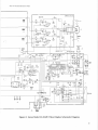
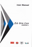
Figure 7 Sanyo Model 20-EZV Video Display Schematic Diagram, Sheet 1
17
Sanyo 19 11 Standard-Resolution Display
CI04
& - eulo'i:;FR
001
Q !Ol
-r·1-
r
TI
2SC.B,CF:.E:r)
oS
IOOfE
:
rt
0104
£Q~Ol -
FR OM
MA IN Cll?(U I T 1lOARO
---- ~Al>'
IZ.
: N v E_ RI
_,u1
mr
FROM
MAIN CIRCU IT S OARD
8- RUFI'(~
- - ---- -
-
··- -
" "~'"1----"'~--------------------~
11Jk
_J- -
_ _ _ _ _ ____.I
Sl&NAL CIRCUIT
~ ::: .\RO
NON
I N\/fkl t l U I
U FOOl~
WARNING
This product contains critical electrical and
mechanical parts essential for X-ray radiation protection. For continued protection,
use only type parts shown in the parts list.
The A symbol and the shaded areas on this
schematic diagram indicate parts essential
for X-ray radiation and safety protection.
Service work should only be performed by
a qualified service technician.
Before servicing or testing this display, you
must install an isolation transformer between
the AC supply and the AC plug of the monitor. The chassis and the heat sink are directly connected to one side of the AC line,
and therefore could present a shock hazard.
The supply voltage of the video display is
90-110 V, 50/60 Hz.
Figure 7 Sanyo Model 20-EZV Video Display Schematic Diagram, Sheet 2
18
)
Sanyo 19" Standard-Resolution Display
N
0
T
E
s
19
Sanyo 19" Standard-Resolution Display
0201 ...... 0'207
ro205. TQ206 . Tlt207 .
1$247J
1')2076
TR 20e.TQ-210.un11
1S 1~
1110
~tOt
OS.•2
-'SC,361F' . CllCJ
25C'i4~A{P . QIXJ
2SC.94!lil.fP . QUl
...... QI06
2'5C::!a.J4CF . GI
1111
Sl"""I'"'VT
• G
)
n
I
"""TAO.. CIROJIT
"""""i.ea... •J
1
I
I
~~ l~ ·ii:
~
EJ>
vQ3'12
0•200K
Cf'Ot82llt
GFOt82.l01
~
'""'''J
•-200K
GF"0182lal
G'FOISZll>I
~
·-"""''
CJ="OIUXB
GF'Ola.3:04
ill
WARNING
This product contains critical electrical and mechanical parts essential for X-ray
radiation protection. For continued protection, use only type parts shown in the
parts list. The
symbol and the shaded areas on this schematic diagram
indicate parts essential for X-ray radiation and safety protection.
A
Service work should only be performed by a qualified service technician.
Before servicing or testing this display, you must install an isolation transformer
between the AC supply and the AC plug of the monitor. The chassis and the
heat sink are directly connected to one side of the AC line, and therefore could
present a shock hazard. The supply voltage of the video display is 90-110 V,
50/60 Hz.
20
MAIN CHASSIS CIRCUIT BOARD
UF0276
Sanyo 19" Standard-Resolution Display
!~1-..,.T~ J
1<'26•
2SC1~711<. L . ~I
'"""'°
2SCl7~1C . 0.£1
n65
1/2CIOOO
....,,J =
9~ IOI(
>200
• 200
110
ll
'"°"
K2'1
~
/
~~
.,..,
\
?~~~
C . P J4
19
,.--------
E3'0t
=
'"""'°
1/2C IOOO
ll
0207
'"""'°
1111
/
(
~·-~
Gll25
XJIS
""""' ·""25e
Cll1U11
GlllAJO-t
Gl125X>I
FROM MAIN
CHASSIS CIRCUIT BOARD
...... 03
o+-...-----lr-+ g~~c;-DDM
••<>7
!"...:.
'"'
l
I
COJ
C.474
= ;:::
lrO~~J_~·_it_
I
-,;;; COii..
von
: :~
COIL
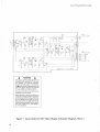
Figure 8 Sanyo Model 20-Z2AW Video Display Schematic Diagram
21
Sanyo 19 11 Standard-Resolution Display
N
22
0
T
E
s
WatTatlty
Seller warrants that its printed-circuit boards and parts thereon are free from defects in material
and workmanship under normal use and service for a period of ninety (90) days from date of
shipment. Seller warrants that its video displays and laser video ·disc players (in games supplied
with displays and video-disc players) are free from defects in material and workmanship under
normal use and service for a period of thirty (30) days from date of shipment. None of the Seller's
other products or parts thereof are warranted.
If the products described in this manual fail to conform to this warranty, Seller's sole liability
shall be, at its option, to repair, replace, or credit Buyer's account for such products which are
returned to Seller during said warranty period, provided:
(a) Seller is promptly notified in writing upon discovery by Buyer that said products are defective;
(b) Such products are returned prepaid to Seller's plant; and
(c) Seller's examination of said products discloses to Seller's satisfaction that such alleged defects existed and were not caused by accident, misuse, neglect, alteration, improper repair,
installation, or improper testing.
In no event shall Seller be liable for loss of profits, loss of use, incidental or consequential damages.
Except for any express warranry set forth in a written contract between Seller and Buyer which contract
supersedes the terms herein) this warranry is expressed in lieu ofall other warranties expressed or implied)
including the implied warranties of merchanmbiliry and fitness for a particular purpose) and ofall other
obligations or liabilities on the Seller)s part) and it neither assumes nor authorizes any other person to assume
for the Seller any other liabilities in connection with the sale ofproducts by Seller.
The use of any non-Atari parts may void your warranty, according to the terms of the warranty.
The use of any non-Atari parts may also adversely affect the safety of your game and cause injury
to you and others. Be very cautious in using non-Atari-supplied components with our games,
in order to ensure your safety.
Atari distributors are independent, being privately owned and operated. In their judgment they
may sell parts or accessories other than Atari parts or accessories. Atari Games Corporation cannot
be responsible for the quality, suitability or safety of any non-Atari part or any modification
including labor which is performed by such distributor.
JI\_®
ATARI
G A M E S
•·
·,,
...,,. ....~.._. \