1
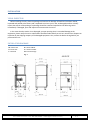
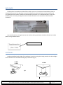
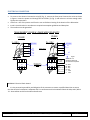
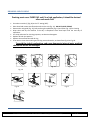
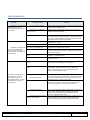
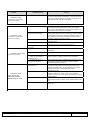
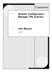
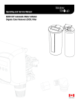
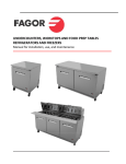
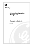
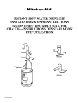
SERVICE MANUAL ********** 2013 DOOR STYLE DISHWASHER DOOR STYLE DISHWASHER Model: AD‐120CW Contents SPECIFICATIONS ...................................................................................................................................................3 AD – 48 W ............................................................................................... ERROR! BOOKMARK NOT DEFINED. AD ‐ 64 CW .............................................................................................. ERROR! BOOKMARK NOT DEFINED. AD – 72 W ............................................................................................... ERROR! BOOKMARK NOT DEFINED. INSTALLATION ......................................................................................................................................................4 VISUAL INSPECTION .........................................................................................................................................4 INSTALLATION DIAGRAMS ...............................................................................................................................4 DATA PLATE ..........................................................................................................................................................4 POSITIONING ...................................................................................................................................................5 WATER INSTALLATION .........................................................................................................................................6 REQUESTED QUALITY OF THE WATER .............................................................................................................7 WATER DRAINAGE INSTALLATION .......................................................................................................................7 ELECTRICAL CONNECTION ...................................................................................................................................8 TRANSFORMATION OF PHASES .................................................................. ERROR! BOOKMARK NOT DEFINED. INSTALLATION CHECKLIST ....................................................................................................................................9 OPERATION ....................................................................................................................................................... 10 TURNING THE MACHINE ON ......................................................................................................................... 10 PREPARING THE MACHINE ........................................................................................................................... 10 WASHING ...................................................................................................................................................... 10 DRAINING AND CLEANING ................................................................................................................................ 11 DETERGENT CONTROL ...................................................................................................................................... 11 PREPARING THE WARE...................................................................................................................................... 14 DELIMING ...................................................................................................................................................... 14 TROUBLESHOOTING .......................................................................................................................................... 15 ELECTRICAL DIAGRAMS ..................................................................................................................................... 18 WIRING SCHEMATICS ................................................................................................................................... 20 RECOMMENDED SPARE PARTS ................................................................... ERROR! BOOKMARK NOT DEFINED. LIMITED WARRANTY ......................................................................................................................................... 21 For Customer Service: Call 1‐866‐GO FAGOR – www.fagorcommercial.com | P. II SPECIFICATIONS MODEL:AD‐120CW PERFORMANCE/CAPACITIES Capacities Racks per hr.: 60 Dishes per hr.: 1500 Wash Tank: 11.8gal. / 44.6 liters Water Consumption / Requirements Gallons per hr. (Max. use): 48 gal. / 181 liters Gallons per cycles: .8gal. / 3.02 liters Inlet temperature (Optimum): 140ºF / 60ºC Flow rinse pressure: 15 – 25 psi Wash Pump Motor Motor (hp): (2) 1 hp Temperatures Wash: 150ºF / 66ºC Rinse: 190ºF / 88ºC TECHNICAL SPECIFICATIONS Total Power Consumption Volts Amps Power (KW) 208/60/3 47.6 14.4 220/60/3 50.1 16.1 240/60/3 53.2 19.2 Pump Power Consumption Volts Amps Power (KW) 208/60/3 5.2 1.2 220/60/3 5.4 1.2 240/60/3 6 1.2 Total Power Consumption Volts Amps Power (KW) 208/60/1 75.1 14.4 220/60/1 79.1 16.1 240/60/1 85.8 19.2 Pump Power Consumption Volts Amps Power (KW) 208/60/1 5.2 0.9 220/60/1 5.4 1.0 240/60/1 6 1.2 Heating Elements Electric wash tank heater: 4.5 Kw Electric booster heater: 12 Kw Operating Cycles Wash time (Seconds): 3 settings (35,55,100) Dwell (Seconds): 5 Rinse time (Seconds): 15 Total Time (Seconds): 3 settings (55,75,120) Dimensions / Shipping Width: 28 1/4” / 717 mm Depth: 32” / 813 mm Height: 62” / 1575 mm Max clearance for dishware16 ½” / 419 mm Rack: 20” x 20” / 500mm x 500mm Shipping weight: 330 lbs. / 150 kg Shipping volume (cu. ft.): 32 Boiler Power Consumption Volts Amps Power (KW) 208/60/3 32.2 9.8 220/60/3 33.8 11 240/60/3 35.4 13.1 Boiler Power Consumption Volts Amps Power (KW) 208/60/1 52.2 9.8 220/60/1 54.9 11 240/60/1 59.4 13.1 For Customer Service: Call 1‐866‐GO FAGOR – www.fagorcommercial.com | P. 3 INSTALLATION VISUALINSPECTION Before installing the unit, check the package and machine for damage. All machines have been tested, inspected and packed at the factory and is expected to arrive to you in new, undamaged condition. Visually inspect the exterior of the package. Any damage should be noted and reported to the delivering carrier immediately. If damaged, open and inspect the contents with the carrier. In the event that the exterior is not damaged, yet upon opening there is concealed damage to the equipment, please notify the carrier. Notification should be made verbally as well as in written form. Request an inspection by the shipping company of the damaged equipment. Also, contact the dealer through which you purchased the unit. INSTALLATIONDIAGRAMS W = Water inlet D = Drain hose C = Electrical R = Terminal Block V = Vacuum breaker M = Pressure Gauge Fig. 1 For Customer Service: Call 1‐866‐GO FAGOR – www.fagorcommercial.com | P. 4 DATAPLATE The data plate in located on one side of the machine. Under no circumstances should the data plate be removed from the unit. The data plate is essential to identify the particular features of your machine and is of great benefit to installers, operators and maintenance personnel. It is recommended that, in the event the data plate is removed, you copy down the essential information in this manual for reference before installation. Any transformations or changes made on the machines during installation should be reflected on the data plate or using a label as below: Total load at indicated POSITIONING Leveling and adjusting the height of the appliance is done by turning the leveling stands to the desire height. Ensure that the unit is level before making any connections (Fig. 2). FI‐48W FI‐72W FI‐64W Fig.2 For Customer Service: Call 1‐866‐GO FAGOR – www.fagorcommercial.com | P. 5 WATERINSTALLATION Water installation is carried out as shown in figures 3 and 4. The hot water line to the dishwasher must provide between 25±5 psi of water pressure. The hot water heater should be set to deliver 140F (not lower than 120°F) water temperature to the dishwasher for best results. Use ¾” copper tubing inlet line. S = Gate valve F = Filter H = Hose E = Fill valve M = Pressure Gauge R = 3/4” Copper V = Vacuum breaker T = Lid Fig. 3 CAUTION: Do not confuse static pressure with flow pressure. Static pressure is the line pressure in a “no flow” condition (all valves and services are closed). Flow pressure is the pressure in the fill line when the solenoid valve is opened during the cycle THE DISPLAY OF THE PRESSURE GAUGE SHALL BE CLEARLY VISIBLE OF THE OPERATOR OF THE MACHINE. THE GAUGE SHALL HAVE INCREMENTS OF 1 psi (7 kpa) OR SMALLER AND SHALL BE ACCURATE TO ±2 psi (±14 kpa) IN THE 20 psi (103‐172 kpa) RANGES. IF THE GAUGE IS LOCATED UPSTREAM OF THE CONTROL VALVE, IT SHALL BE MOUNTED IN AN ACCESSIBLE VALVE WITH A ¼ IN IRON PIPE SIZE CONNECTION. If the water pressure is less than 20 psi (1.4 kg/cm2), installation of a water pump is required as shown in Fig. 4. In areas where the pressure fluctuates or is greater than the recommended pressure, it is suggested that a water pressure regulator be installed. S = Stop cock F = Filter H = Hose E = Electro valve B = Electro pump M = Manometer R = ¾” Copper For Customer Service: Call 1‐866‐GO FAGOR – www.fagorcommercial.com | P. 6 REQUESTEDQUALITYOFTHEWATER ‐Hardness: 5‐10º F ‐Conductivity 200‐2000 µS ‐pH 6.5 – 7.5 ‐Chloride’s concentration < 150 m g/litre ‐Chlorine 0.2‐0.5 mg/litre ‐Impurities < 0,08 mm It is necessary to remove all foreign debris from the water line that may potentially get trapped in the valves or cause an obstruction, prior to connecting to the machine. Use only the supplied hoses (3/4” Female hose connector) at the water connections. Failure to do so may result in damage to the solenoid valve threads and leaking. Tighten by hand. Connect the bent side of the hose to the machine. Adaptor supplied for ¾” female garden hose connection. FOR HARD WATER SUPPLIES WITH A HARDNESS OF OVER 2 GRAINS OR 10ºF AND PH BEYOND THE RANGE OF 7.0 – 8.5, A WATER CONDITIONER MUST BE INSTALLED. Slowly turn on the water supply to the machine after the incoming fill line and the drain line have been installed. Check for any leaks and repair as required. All leaks must be repaired prior to placing the machine in operation. WATERDRAINAGEINSTALLATION 2 3/8" Attach the drain hose as shown in Fig. 5. It is recommended to affix a siphon pipe to prevent odors. All piping from the machine to the drain must be a minimum 1‐1/2” I.P.S. There should also be an air gap between the machine drain line and the drain. For natural overflow efficiency use floor drain. D = Drain hose C = Drain collector A = Air Gap F = Scrap Basket Fig. 5 For Customer Service: Call 1‐866‐GO FAGOR – www.fagorcommercial.com | P. 7 ELECTRICALCONNECTION To access to the electrical connection strip (R) (Fig. 1), remove the front panel. Connect the wires as shown in figure 6. Insert the power cord through the cord holder (C) (Fig. 1) and make sure to leave enough cable. Tighten the connections. Leave free 39” of the power cord from the rear to facilitate cleaning of the location of the dishwasher. Install a circuit breaker in accordance to required consumption guidelines and data plate. The machine must be grounded. THANK ELEMENT 3-PHASE & 1-PHASE WIRING SCHEMATIC 1-PHASE 3 -PHASE 3 ~ 220 V. 1N ~ 230V. GROUND Y/G BL GY BK BK, BR,GY N BL GY T S BR R BK L1 TERMINAL BLOCK T L2 S L3 BR BK, BR,GY 1 1 BK BR GY BR G TANK CONTACTIOR Z203050 CT BK BR GY BR GY BK Y CT BK BK Y BR BR GY GY Legend 1 1 BK BR GY BR G L2 R 2 2 2 2 1 N GROUND L1 Prensa estopas Rc: 12 Kw. R-033002 1N Remove 1x Z683097 16mm² 3x 683069 16mm ² Install 2x R263003 35mm² Wire Bundle "1" is idintified as a thicker wire with a Blue wire incorporated BR BK GY BL Y G Brown Black Gray Blue Yellow Green WARNING: Electrical Shock Hazard It is the personal responsibility and obligation of the customer to contact a qualified electrician to assure that the electrical installation is adequate and is in conformance with the National Electrical Code, ANSI / NFPA 70 – latest edition and all local codes and ordinance. For Customer Service: Call 1‐866‐GO FAGOR – www.fagorcommercial.com | P. 8 INSTALLATIONCHECKLIST CHECK OFF THE FOLLOWING ITEMS AS THEY ARE COMPLETED BEFORE PROCEEDING TO OPERATE OR SERVICE THE DISHWASHER. Has the dishwasher been properly leveled? Has the service voltage been checked to ensure that it meets the requirements listed on the dishwasher specifications (Page 2)? Circuit Breaker size ______ Voltage ______ Phase _______ Existing or New electrical install _______ Has the dishwasher been properly grounded? Are the electrical connections and plumbing pipes tightening to proper torque levels? Has been installed with the supplied water hose? If not, Specify specs of the water hose install Thread_____ Size ______ Brand ______ Flush water supply line before opening water valve Is the water valve open? Is the incoming water supply at 20 ‐ 25 psi? Verify water hose, drain hose and chemical hoses are not kinked? Is the hot water supply at the optimum temperature (140ºF)? If not, list water temperature _______ °F Is the water hardness ≤2.0gpg/34.2ppm and PH level 7 ‐ 8.5ph? Has the drain plumbing been installed according to the instructions in this manual? Height of the drain hose ______ Air gap size _______ Was the drain installed to a garbage disposal? If yes, has been installed a back flow safety in case the garbage disposal fail? ____ Damages to a drain pump due to a failure of a garbage disposal will not be covered under warranty Is the overflow tube with the O‐ring fitted in its position inside the tank Is the detergent for commercial dishwashers? Have you adjusted the amount of detergent / rinse going to the machine? ____ Adjustments on detergent/rinse pump are not cover under warranty. Please refer to page 18 for instructions. In order to validate your warranty this checklist must be return to Fagor along with the product registration card. MODEL NO.__________________________ SERIAL NO.___________________________ INSTALLATION DATE ___________________ SERVICE REP. NAME ___________________ PHONE Nº ___________________________ Registration can be completed by mail, phone, and fax or on the website www.fagorcommercial.com Fax: 3057790173 13105 NW 47 Ave. Opa Locka, FL 33054 [email protected] For Customer Service: Call 1‐866‐GO FAGOR – www.fagorcommercial.com | P. 9 OPERATION 9 10 2 1 3 4 5 6 8 7 Fig. 9 TURNINGTHEMACHINEON Press and hold the power button (1) for five seconds. LED # 2 will lit up and the machine will start filling up with water. PREPARINGTHEMACHINE After the machine has filled it will start heating up the rinse tank and the wash tank. The machine is ready to wash when the rinse thermometer (9) indicates 180º F (83˚C) and the tank thermometer (10) 160º F (71˚C). It is the user’s responsibility to wait until the minimum temperatures are displayed before putting the machine to wash. WASHING NOTE: All models are fitted with Thermo‐stop. The temperature of the incoming water should be higher than 120°F/ 50 ºC. (Ideal temp. 140°F/60 ºC) If it is lower, the machine's capacity may be affected and you may have extended cycles. There are 3 washing cycles for models described before: P1 (3), P2 (5) and P3 (7) of 60, 90 and 180 seconds respectively. (Fig.7). LED’s numbers 4, 6 and 8 indicate that the machine is working; depending on selected programme, one or other led will switch on. If you start your dishwasher prior to your booster heater (9) reaching a minimum of 180º F (83ºC), YOU WILL HAVE AN EXTENDED WASH CYCLE! For Customer Service: Call 1‐866‐GO FAGOR – www.fagorcommercial.com | P. 10 DRAININGANDCLEANING Draining must occur EVERY DAY and if in a high application; it should be drained after each meal rush! Set selector switch (1) (Fig. 8) to the “0” setting (OFF). Raise hood and remove overflow tube to drain the unit (Fig. 13). DO NOT LOOSE O’RING! Remove the rack guide (Fig. 12), Bulk and Long Scrap Baskets (Fig. 10) and Filter (Fig. 11) for cleaning Wipe clean and dry the machine if the day is completed. Leave hood open until the next day of operations. Use soap and water for cleaning purposes, not abrasive detergents Replace all back into position Replace the overflow tube with O‐ring From time to time clean washing and rinsing arms and nozzles, as shown from Fig.14 to Fig. 18. To avoid the risk of overheating, and cause damage to internal parts, machine should not be left on overnight Fig. 11 Fig. 10 Fig. 12 Fig. 13 Fig. 14 Fig. 15 Fig. 16 Fig. 17 For Customer Service: Call 1‐866‐GO FAGOR – www.fagorcommercial.com | P. 11 DETERGENTCONTROL Use ONLY Commercial Grade, High Temperature, Low Suds Liquid Detergent. Fagor doesn’t recommend any specific brand name of chemicals. Contact your local chemical distributor for questions concerning your chemical needs. All machines come equipped with an internal Detergent and Rinse dispenser. Take the tube located in the back or your machine marked “Detergent” and place inside detergent container. Take the tube with a blue stripe mark and place inside rinse container. Tubes are clear to provide you a visible means that chemicals are being dispensed. If desired you can control the amount of Chemical being dispensed by opening the bottom front panel of the machine. Locate the detergent dispenser (Fig. 9) and regulate according to the flow chart (Fig. 9a). For the Rinse, turn the button counterclockwise to get more rinse aide and clockwise for less. Verify all connections to the dispenser are hand tighten to prevent any leaks. Control and maintain the level of detergent and rinse aid of the tanks. Keep chemical tubing and filters submerged. DETERGENT PUMP DETERGENT ADJUSTMENT Gal./h. 220º Oº 1 7 1 0 2 6 2 0.06 3 0.20 3 5 4 0.40 4 5 0.53 6 0.66 Fig.9a 7 0.80 Fig. 9 RINSE PUMP RINSE PUMP ADJUSTMENT Warning! If you require the installation of an NON FAGOR Detergent and Rinse pump, a form MUST be fill out prior to installation by your installer. Failure to do so will void your Warranty. This form can be located inside your dishwasher. If lost, please contact Fagor to get a copy. Note: The detergent pump and rinse dispensing pump will only work during the process of fill and rinse. For Customer Service: Call 1‐866‐GO FAGOR – www.fagorcommercial.com | P. 12 InstallationofExternalChemicalPumps If you require the installation of an NON FAGOR Detergent and Rinse pump, a form MUST be fill out prior to installation by your installer. Failure to do so, will VOID YOUR WARRANTY!! This form can be located inside your dishwasher. If lost, please contact Fagor to get a copy. Dishwasher already incorporates a terminal block where you can connect an external chemical pump. Remove Right panel and locate terminal block (Fig. 25). Green and Violet are the connections for detergent. Green and White are the connections for rinse. Fig. Chemical Injectors: 1) Place External Detergent Injector at the back side of the machine above the stainless steel scrap filters. SOME MODELS INCORPORATE PREDRILLED HOLE AT THE BACK OVER WATER LEVEL. REMOVE PLUG FROM THE TANK AND FIT DETERGENT INJECTOR . 2) Remove black hose connected to the current rinse dispenser. Connect External Rinse Injector into the black hose. (Fig. 26) Black hose Fig. 26 3) If a PH sensor or similar is required, this can be installed between washing pumps pipes. Remove Right Panel to have access to that area. SOME MODELS INCORPORATE PREDRILLED HOLE AT THE BACK, MIDDLE HEIGHT OF THE TANK. REMOVE PLUG FROM THE TANK AND FIT PH SENSOR THROUGH IT. Also it is recommended to disconnect detergent pump that comes with the machine. Remove electrical connections and protect terminals, to prevent shortcuts. For Customer Service: Call 1‐866‐GO FAGOR – www.fagorcommercial.com | P. 13 PREPARINGTHEWARE Pre‐scrap and rinse all racks prior to placing them in the dishwasher to remove large food particles (pre‐ scrap) from the ware. Wash glassware first Put trays in the baskets, making sure is in its separate rack (Fig.12). Put plates in the baskets, making sure each is in its separate rack (Fig. 11). Put glasses in upside down. Put cutlery in the cutlery baskets handles down. Mix spoons with knives and forks. (Fig. 10) Put the special cutlery baskets in the base baskets. Fig. 10 Fig. 11 Fig.12 DELIMING In order to maintain dishwasher at optimum conditions, it is requested to remove lime and corrosion deposits on a frequent basis. A de‐liming solution should be available from your chemical supplier. Read and follow all instructions on the label of the de‐liming solution. Operations: Fill the machine. Add the correct amount of de‐liming solutions as recommended by the de‐liming solution manufacturer. The water capacity of the tank can be verified on the specification sheet of this manual Remove detergent and rinsing tubes from containers so no chemicals go to the machine Run the machine for the recommended period of time. As many cycles as needed. Turn off the machine and open the door. When clean, drain and re‐fill the machine and Run machine for 3‐4 cycles to remove de‐ liming solution Drain the machine. For Customer Service: Call 1‐866‐GO FAGOR – www.fagorcommercial.com | P. 14 TROUBLESHOOTING SYMPTOM Dishwasher will NOT FILL after the door is closed. Power “ON” light (L1) is not illuminated. POSSIBLE CAUSE Service breaker tripped Machine not connected to power source. Faulty Circuit Board No water to machine Machine not level Dishwasher will NOT FILL or reach the appropriate water level after the door is closed. Power “ON” light (L1) is illuminated. Overflow tube not attached or broken / missing O-ring. Faulty door switch Faulty fill pressure switch (P1) Faulty rinse/fill valve (V) Verify the unit is connected to a hot (live) feed. Verify voltage and proper phasing. Make sure power is being supplied to the board. Check for loose wiring harness connections. Check circuit board fuse. Check voltage between R (brown) and N (blue). If 208V-240V found, replace circuit board. Verify hose is not blocked or kinked, water valve is open and pressure > 20 psi. Level machine. Legs are height adjustable. Check condition of overflow tube. Make sure O-ring is in good working condition and in place. Verify the wiring at the switch for loose connections; if no loose connections are present, replace the switch (Ip) or the door relay (Cp) Verify voltage at terminal 2 (brown) and GND. If no voltage, P1 is possible stuck. Verify the wiring and proper voltage at valve; if correct replace fill valve. Verify it changes position of the switch; on terminal 1 to 2 (fill), and 1 to 3 (heating) If not replace it. Faulty Power/Start button Verify good connection between digital start buttons and circuit board. If disconnected, reconnect and verify. Verify circuit board fuse is If connected and still not working, replace Adhesive Trim. (St) Faulty Circuit board Faulty wash pump (MBL) Faulty start buttons Rinsing temperature gauge is lower than 180ºF. Reset. If the breaker trips again, contact an electrician to verify amps or possible short. Faulty fill pressure switch (P1) Dishwasher will NOT RUN after the door is closed. Power “ON” light (L1) is illuminated and the unit has completed the filling and heating cycle. ACTION Make sure power is being supplied to the board. Check for loose wiring harness connections. Check circuit board fuse. Check voltage between R (brown) and N (blue). If 208V-240V found, replace circuit board. Rotate the pump from the shaft flat head slot counterclock wise to verify free rotation. Verify that the wash pump is getting power. If so, replace the pump. Verify good connection between digital start buttons and circuit board. If disconnected, reconnect and verify. Verify circuit board fuse is If connected and still not working, replace Adhesive Trim. Wait until sanitized rinsing temperature reached a min.of 180ºF. Check out your incoming water temperature. Recommended incoming water temperature is 140°F For Customer Service: Call 1‐866‐GO FAGOR – www.fagorcommercial.com | P. 15 SYMPTOM POSSIBLE CAUSE Faulty Circuit Board Make sure power is being supplied to the board. Check for loose wiring harness connections. Check circuit board fuse. Check voltage between R (brown) and N (blue). If 208V-240V found, replace circuit board. Faulty Circuit Board Make sure power is being supplied to the board. Check for loose wiring harness connections. Check circuit board fuse. Check voltage between R (brown) and N (blue). If 208V-240V found, replace circuit board. Verify rinse gauge temperature is above 180°F. If above, replace circuit board. If rinse temperature <180°F replace Tc thermostat and/or boiler element and heater relay. If A4 is displayed, reconnect temperature sensor. If A5 is displayed, replace temperature sensor. Verify the wiring and correct voltage at valve; if correct replace fill valve. Verify hose is not blocked or kinked. Verify the inlet water pressure is at a min of 20 psi and max 25 psi. Remove and clean rinse arms/nozzles. Dishwasher RUNS continuously in the wash cycle or not rinsing. Faulty Operating t-stat (Tc)/Faulty Circuit Board Dishwasher RUNS continuously in the wash cycle or not rinsing. Faulty rinse/fill valve (V) No water to machine. Clogged or obstructed rinse arms Poor water pressure Dishwasher FILLS slowly and/or rinse is weak. Hose strainer is clogged Bad rinse/ fill valve (V) Valve can be clogged causing poor flow. Temperature gauge in front panel is defective. Misadjusted/faulty thermostat (Tc) Faulty high limit stat (Tl) Dishwasher RUNS. RINSE WATER NOT REACHING MINIMUM TEMPERATURE OF 180°F ACTION Faulty heater relay (Cc) Faulty Boiler element (Rc) Verify the inlet water pressure is at a min of 20 psi and max 25 psi. Check strainer or any filters installed. Disconnect hose from fill valve and check filter screen inside for debris. Replace rinse/fill valve as needed. Check temperature with a calibrated thermometer at the corresponding temperature sensor location. Replace temperature gauge as needed. Verify rinse temperature probe sensor is properly inserted inside probe well. Replace Tc thermostat and/or boiler element and heater relay. If A4 is displayed, reconnect temperature sensor. If A5 is displayed, replace temperature sensor. Reset thermostat by depressing red button. Replace if necessary. Make sure heater relay (Cc) is working properly (not stuck in or out) and Tc thermostat is cutting off below 195°F Verify voltage at heater relay coil (A1, A2), solenoid closes when receiving voltage. If not, replace heater relay (Cc). Ohm out element check for continuity; if open, replace heater (Rc). For Customer Service: Call 1‐866‐GO FAGOR – www.fagorcommercial.com | P. 16 SYMPTOM POSSIBLE CAUSE Low incoming water temperature supplied to the Dishwasher Faulty thermostat (Tc) Dishwasher RUNS. WASH WATER NOT REACHING REQUIRED TEMPERATURE OF 150°F Misadjusted/faulty thermostat (Tt) Tank heater relay (Ct) faulty. Tank heater (Rt) faulty Door is closed Overflow tube not removed. Drain pump (BD) clogged. Drain hose kinked Dishwasher Washes and Rinses but Does NOT DRAIN or overflows. Faulty Drain pump (BD) Faulty safety pressure switch (P2), Overflow. Machine temperatures or pressure may not be to specification. None or too little detergent being used. Improper loading or overloading Washing and or rinsing arms jammed or dirty. Clogged drain Dishes are not coming out clean enough. Machine not level Excessive inlet pressure WATER OVERFLOW FROM BOTTOM OF THE DOOR Rinse agent not being dispensed EXCESS FOAM coming out of the door. Low water pressure, rinse aid container is empty, air in the pump and/or lines. Detergent tubes not placed properly inside container/improper adjustment ACTION Check out that incoming water temperature is at least 120°F and pressure is at least 20 psi. Optimal incoming water temperature is 140°F and optimal incoming water pressure is 25 psi. Verify that there is power on violet (vi) coming from Tc to Tt (only applies after Tc has been satisfied or > 180°F). If A4 is displayed, reconnect temperature sensor. If A5 is displayed, replace temperature sensor. Verify voltage to t-stat. If voltage has been verified ok, check tank heater relay Ct Verify voltage at heater relay coil (A1, A2), solenoid closes when receiving voltage. If not, replace heater relay (Ct) Ohm out (between 10-12 Ohms) element check for continuity; if open, replace heater (Rt). Open the door and push the drain button for 3 sec. Open the door and remove the Front Right S/S Filter and remove the overflow tube by inserting a finger through the hole on top of the overflow tube and pull upward. Open drain pump cover and remove debris. (Lower front panel; unscrew white removable cover, rotate counterclock wise Make sure the drain hose is not kinked and flush out any debris that may have been accumulated. Verify voltage to drain pump; if receiving voltage, replace Drain pump (BD). Verify that the black rubber pressure tube is not kinked or damaged (air leak). If so, replace black rubber pressure tube. If not kinked or damaged, replace pressure switch P2. Wait until sanitized rinsing temperature reached a min.of 180ºF. Check out your incoming water temperature. Recommended incoming water temperature is 140°F and incoming water pressure is 20-25 psi. Make sure detergent to dish ratio is fallowed to manufacturer specification. Make sure that the detergent and rinse pumps have been adjusted and primed (priming only applies to the rinse pump). Check for kinks along the chemical lines. Make sure that the chemical line brass filters are completely submerged below the chemical level. Read chapter on proper loading of dishwasher. Refer to page 15 of this manual. Check that arms rotate properly by spinning them manually and that rinsing and washing nozzles are not blocked or dirty. Clean if necessary Remove obstruction from the pump and/or make sure the drain hose is not kinked and flush out any debris that may have been accumulated. Level machine by adjusting the unit’s legs accordingly. Refer to page 6 of this manual Install pressure reducing valve. Ensure flow is 20-25 psi. Use ONLY commercial grade, low suds, liquid detergent for commercial appliances. Adjust the amount of chemicals being dispensed to the unit. Refer to page 14 of this manual. Verify that the min. incoming water pressure is 20 psi. Verify that there is enough rinse aid left in the container. Make sure that the rinse agent chemical lines are primed and free of kinks. Verify detergent tubes are secured inside container Adjust chemicals to proper levels For Customer Service: Call 1‐866‐GO FAGOR – www.fagorcommercial.com | P. 17 DIAGNOSTICS . ON/OFF LED FLASHING: Errors or Faults are notified by flashes of the ON/OFF LED. The flashes stay on for half second, followed by 2 seconds off. On On Off On On Off Example of a 2 flashes ERROR ( Tank Water Fill Error) 1 Flash ( OPEN DOOR): This is indicated by a one flash and a pause. This continues as long as the door is open and the selected cycle is unfinished. 2 Flashes ( TANK FILL ERROR): This is indicated by a two flashes and a pause. This continues while the water in the tank does not reach the correct level in the specified time. 3 Flashes ( TANK DRAINAGE ERROR): This is indicated by a three flashes and a pause. This continues while the drainage pump does not drain the water in the tank to the correct level in the specified time. 4 Flashes ( BOILER HEATING ERROR): This is indicated by a four flashes and a pause. This continues while the water in the boiler does not reach the correct temperature in the specified time. 5 Flashes ( TANK HEATING ERROR): This is indicated by a five flashes and a pause. This continues while the water in the tank does not reach the correct temperature in the specified time. TEMPERATURE PROBE ERROR: The display may show different alarms for the temperature probes. The alarm is shown on the corresponding display ( boiler temperature display or tank temperature display). A4 : “Temperature probe open” alarm: A5: “Temperature probe short-circuit” alarm: For Customer Service: Call 1‐866‐GO FAGOR – www.fagorcommercial.com | P. 18 ELECTRICALDIAGRAMS For Customer Service: Call 1‐866‐GO FAGOR – www.fagorcommercial.com | P. 19 WIRINGSCHEMATICS For Customer Service: Call 1‐866‐GO FAGOR – www.fagorcommercial.com | P. 20 LIMITEDWARRANTY One Year Parts & Labor Warranty: Fagor Commercial, Inc. (“Fagor”) warrants to the first-end-user purchaser (the “User”) that the Fagor brand equipment sold hereunder, except for parts and accessories which carry the warranty of a supplier (the “Equipment”) will be free from defects in material and factory workmanship under normal conditions of use and maintenance for a period of (1) one year from the date of Installation (Warranty Commencement Date), but in no event to exceed (15) fifteen months from the date of shipment. Warranty Coverage: If there is a defect in material or factory workmanship covered by this Warranty reported to Fagor during the period the applicable Warranty is in force and effect, Fagor will repair or replace, at Fagor’s option, that part of the Equipment that has become defective. Fagor will cover labor cost within one year from the Warranty Commencement date or 15 months from shipment date, whichever occurs first with the exception of the Glasswasher models, which will be 90 days labor and one year parts warranty. Fagor shall bear all labor costs in connection with the installation of these replacement parts, provided that, the installation is conducted by Fagor or its authorized representative. Charges for warranty travel time to round trip total (2) two hours or up to 100 miles. Any charges exceeding those stated herein must have prior authorization by Fagor. In case Fagor deems the equipment non-repairable, said equipment will be replaced and the replacement unit(s) will carry the same warranty period from the original unit’s installation date (Original Warranty Commencement Date). Exclusions from and Conditions to Warranty Coverage: This Warranty does not cover parts or accessories, which (a) carry the warranty of a supplier or (b) are abused. Application of this Warranty is further conditioned upon the following: • Installation. The Equipment must be properly installed in accordance with Fagor’s installation procedures and instructions and reviewed and tested by a professional technician. • No Alteration. The Equipment must not have been modified or altered from its condition at the date of original installation. • Use. FAGOR EQUIPMENT IN NOT DESIGNED FOR PERSONAL, FAMILY OR HOUSEHOLD PURPOSES, AND ITS SALE FOR SUCH PURPOSES IS NOT INTENDED. IN THE EVENT THE EQUIPMENT IS SO USED, THIS WARRANTY SHALL BE NULL AND VOID, AND THE EQUIPMENT SHALL BE DEEMED TO HAVE BEEN SOLD “AS IS-WHERE IS” WITHOUT ANY WARRANTY OF ANY KIND, INCLUDING WITHOUT LIMITATION ANY WARRANTY OF TITLE, NON-INFRINGEMENT, MERCHANT-ABILITY OR FITNESS FOR A PARTICULAR PURPOSE. • Water Quality. Water supply should have hardness between .25 and 2.0 grains per gallon, pH level between 7.0 – 8.5 and TDS level at 250 PPM. Equipment failure due to inadequate water supply is not covered by this Warranty. • Proper Maintenance and Operation. The Equipment must be properly maintained and operated in accordance with Fagor’s maintenance and operating procedures. All service, labor and parts must be acquired from Fagor or its authorized service representative for the User’s area. • Minor Parts. No labor will be associated with the replacement of minor items such as, and not limited to, switches, pilot lights, gauges, fuses, etc. or replacement of wear items such as curtains, squeeze tubes, etc. • This warranty is void if failure is a direct result of handling &/or transportation, fire, water, accident, misuse, acts of God, attempted repair by unauthorized persons, improper installation, if serial number has been removed or altered, or if unit is used for purpose other than it was originally intended. Failure to comply with any of these conditions will void this Warranty. In addition, this Warranty does not cover defects due to apparent abuse, misuse or accident. Fagor will have no responsibility to honor claims received after the date the applicable Warranty expires. Notwithstanding the foregoing, any claim with reference to the Equipment or any parts therefore for any cause shall be deemed waived unless submitted by the User to Fagor within thirty (30) days after the date the User discovered, or should have discovered, the claim. In connection with all claims under this Warranty, Fagor will have the right, at its own expense, to have its representatives inspect the Equipment at the User’s premises and to request all of User’s records pertaining to the Equipment to determine whether a defect exists, whether the conditions set forth in this Warranty have been satisfied, and whether or not the applicable Warranty is in effect. THE FOREGOING WARRANTY IS IN LIEU OF AND EXCLUDES ALL OTHER WARRANTIES NOT EXPRESSLY SET FORTH HEREIN, WHETHER EXPRESS OR IMPLIED BY OPERATION OF LAW OR OTHERWISE, INCLUDING BUT NOT LIMITED TO ANY REPRESENTATION OF PERFORMANCE AND ANY IMPLIED WARRANTIES OF TITLE, NON-INFRINGEMENT, MERCHANTABILITY OR FITNESS FOR A PARTICULAR PURPOSE. NO OTHER WAR-RANTIES ARE AUTHORIZED ON BEHALF OF FAGOR UNLESS SPECIFICALLY ISSUED BY FAGOR. Fagor shall have no liability for incidental or consequential losses, damages or expenses, loss of sales, profits or goodwill, or punitive or exemplary damages directly or indirectly arising from the sale, handling or use of the Equipment or from any other cause relating thereto, whether arising in contract, tort, warranty, strict liability or otherwise. Fagor’s liability hereunder in any case is expressly limited, at Fagor’s election, to repair or replacement of Equipment or parts therefore or to the repayment of, or crediting the user with, an amount equal to the purchase price of such goods. Fagor Commercial, Inc. 13105 NW 47th Ave. Miami, Fl. 33054 Tel: (305) 779 0170 Fax: (305) 779 0173 1‐866‐GO‐FAGOR www.fagorcommercial.com For Customer Service: Call 1‐866‐GO FAGOR – www.fagorcommercial.com | P. 22