1
Operating and Service Manual
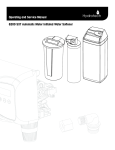
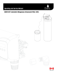
6200 SXT Automatic Meter Initiated
Organic Color Removal (OCR) Filter
Made in Canada
Introduction
Read this Manual First
• Read this manual thoroughly to become familiar with the device and its capabilities before installing or operating your
Water Filter. Failure to follow instructions in this manual could result in personal injury or property damage. This manual will
also help you to get the most out of your filter.
• This system and its installation must comply with state and local regulations. Check with your local public works department for plumbing and sanitation codes. In the event the codes conflict with any content in this manual the local codes
should be followed. For installations in Massachusetts, Massachusetts Plumbing Code 248 CMR shall be adhered to. Consult your licensed plumber for installation of this system.
• This water softener is designed to operate on pressures of 20 psig 125 psig. If the water pressure is higher than the maximum use a pressure reducing valve in the water supply line to the filter.
• This unit is capable of operating at temperatures between 40°F and 110°F (4°C - 43°C). Do not use this water softener on
hot water supplies.
• Do not install this unit where it may be exposed to wet weather, direct sunlight, or temperatures outside of the range
specified above.
• Do not use water that is microbiologically unsafe without adequate disinfection before or after this system.
• This publication is based on information available when approved for printing. Continuing design refinement could cause
changes that may not be included in this publication. WaterGroup reserves the right to change the specifications referred
to in this literature at any time, without prior notice.
Safety Messages
Watch for the following safety messages in this manual:
NOTE: used to emphasize installation, operation or maintenance information which is important but does not
present a hazard.
Example: NOTE: Check and comply with you state and local codes. You must follow these guidelines.
CAUTION: used when failure to follow directions could result in damage to equipment or property.
Example:
CAUTION! Disassembly while under pressure can result in flooding.
WARNING: used to indicate a hazard which could cause injury or death if ignored.
Example:
WARNING! ELECTRICAL SHOCK HAZARD! UNPLUG THE UNIT BEFORE REMOVING THE COVER OR ACCESSING
ANY INTERNAL CONTROL PARTS
NOTE: Do not remove or destroy the serial number. It must be referenced on request for
warranty repair or replacement
1
Application and Installations of Organic Colour Removal Unit
This Organic Colour Removal Filter (OCR) has been designed to remove tannins from your water supply. Tannins can cause
a yellow to brown colour in the water (i.e. organic colour) and also may impact taste and odour as well. Tannins are formed
by the decomposition of vegetable matter. All tannins are not equal, and thus the type of OCR unit selected should have
been with the assistance of an authorized representative or distributor. This is typically done based on a water analysis and
column testing of the source water and/or with experience on other successful installations in the area on the same source
water.
Application Notes about OCR Units:
1. Although the OCR unit was selected using this source water, the selected OCR unit was the most suitable type for this
application, total removable of all colour contaminants may occasionally not be attained due to:
a) Multiple types of tannins in the source water. OCR Unit media may only be successful at removing some of these
organics, but not all.
b) Colour may be caused by contaminants other than organics.
c) The remaining contaminants may require removal by other methods such as activated carbon, reverse osmosis, etc.
Please consult your authorized representative or distributor for solutions.
2. If water hardness is also present (particularly if total hardness > 10 grains/US Gal), a softener must be installed ahead
(upstream) of the OCR unit. Without the softener, the OCR resin bed is prone to fouling by the precipitation of calcium
carbonate. Meter initiated softeners with a reserve capacity are preferred to calendar clock softeners to ensure the
softener is not overrun.
(Installation Tip: Ensure that the OCR Unit is only allowed to regenerate after the regeneration of a water softener if one is
present)
3. Metals in the water such as Iron and Manganese can also foul the OCR resin bed, reducing the ability to remove tannins.
An iron filter or iron guard softener should be used to reduce the problem causing contaminants to an acceptable level.
(Installation Tip: As in item #2, the OCR Unit and any softeners and filters should not be allowed to regenerate at the
same time. Consult the applicable unit owners manuals on regeneration time and adjustment if necessary.)
4. Turbidity caused by suspended solids and sediment can foul the OCR resin bed. Removal of the turbidity can be
achieved through some type of mechanical filtration such as a multi-media filter and/or cartridge filters.
5. Depending on the Alkalinity of the source water being treated, the pH of the water after the OCR unit will likely drop for
part or all of the units service run after regeneration. This is caused by the OCR unit’s resin ability to also remove alkalinity
in the water. Adjustment of the waters pH may be required once treated by the OCR unit.
6. If “nitrates” are present in the source water, consult your authorized representative or distributor for additional solutions.
CAUTION! This unit has not been designed for nitrate removal and should be dealt with separately.
7. Occasionally, a fishy odour will occur if the source water is of a high pH, typically greater than 8.0. If this occurs, putting
the unit through a couple regeneration cycles can sometimes reduce the odour. Chlorine in combination with a higher
pH can also make the odour worse or more difficult to overcome as chlorine degrades the resin in the OCR unit.
8. Depending on the alkalinity of the source water being treated, the chlorides in the treated water from the OCR unit will
increase proportionally. This may result in a bitter salty taste which should be treated with a reverse osmosis drinking water system for household drinking and cooking water
2
Water Chemistry Guideline
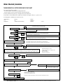
TANNIN REMOVAL FILTER GUIDELINE FLOWCHART
There are two major groups of organics:
• The carboxylic groups - removed by ion exchange by Anion Resin
• The phenolic group - They are non-ionized and can be removed by adsorption
For effective removal, macroporous Type 1 strong base anion resin can bed used.
The performance of removal will depend on organic level, measured in total organic carbon (TOC), presence of iron
The following water contaminants are needed to be tested :
• Total Hardness*
• Iron*
• Manganese*
• Nitrates*
• pH
• Total Dissolved Solids (TDS)*
• Tannins*
• Sulphates*
• Alkalinity*
* Critical
If the hardness and iron is high, the calcium and iron will precipitate and foul the anion
resin which will cause an irreversible change
NO
If Hardness <10 gpg
A separate softener will be required
YES
If Iron < 0.1ppm
Iron Filter is required depending on Fe++, Fe+++ and pH levels, If pH is low and Fe++ concentration is low
<10ppm and no chlorine is present, Softener can be used if properly sized
NO
YES
If Manganese < 0.03ppm
YES
** Check Fe++ and Fe+++ concentration in the field
Manganese Greensand or Iron Filter is required depending on Mn++ and pH levels, If pH is low and Mn++ is
low<0.75 ppm and no chlorine is present, softener can be used
NO
** Check Mn++ concentration in the field
Check Sulphate to Nitrate Ratio to determine the anion resin
Strong Acid Base Anion Resin Selectivity - Sulphate>Nitrates>Chloride>bicarbonate
Strong Acid Base Anion Nitrate Resin Selectivity - Nitrates>Sulphate>Chloride>bicarbonate
If {Nitrate/(Nitrate+Sulphate)}>0.6 (WHO Limit)
Nitrate Selective Resin to be used, Capacity can be calculated by nitrate ions percentage and silica leakage
NO
YES
This is done to avoid nitrate dumping
Check Sulphates, Bicarbonates (alkalinity), Tannins, Nitrates concentration and calculate the capacity of OCR Resin
for each of these substances and and determine the largest CF of anion resin required to be regenerated every three
days - X CUFT (The capacity can be calculated by calculating the percentage of sulphate and the leakage of silica
If Hardness < 10gpg
Size the OCR filter based on the capacity for tannin, sulphate,nitrate and bicarbonate
NO
YES
Tannin removal capacity - 2000 ppm
Sulphate removal capacity - 7000 grains per cubic
feet (Rule of thumb)
Nitrate removal capacity Bicarbonate removal capacity
Calculate the CF of softener resin required to be regenerated every three days - Y CUFT
NO
Go for a separate OCR removal filter
Backwash needs to be 1.8gpm/ sqft
Backwash frequency need be 2 to 3 days
Service Flow Rate - 2USGPM/CF of Resin
Go for OCR combination unit
If pH is <6 and TDS<100
YES
If TDS>500, Use A850 Resin, If TDS<100, Use A860 Resin
Backwash needs to be 1.8gpm/ sqft
Backwash frequency need be 2 to 3 days
Service Flow Rate - 2USGPM/CF of Resin
At low TDS, the deficiency in bicarbonates can decrease the pH of water making it more acidic
Consider Installing a Neutralizing filter after Tannin removal filter
RESIN CLEANING PROCEDURE Soda ash can be used in combination with the salt to keep the resin bed clean. Half to 1 lbs of soda ash can be added to the brine well.
OCR Filter Unit
Otherwise, iron filter or softener needs to installed before
Otherwise, iron filter, softener or manganese greensand unit needs to installed before depending on
Manganese concentration
If <0.6, nitrate selective resin needs to be used
If Hardness >10
If Iron <0.1 ppm
If Manganese <0.03 ppm
If {Nitrate/(Nitrate+Sulphate)}>0.6 (WHO Limit)
Resin Tannin Capacity - 2000 ppm per CuFt of Resin
Sulphate Removal Capacity - 7000 grains/CF of Resin
Flow Rate - 2GPM/CF of Resin
Backwash - 1.8 GPM/SqFT (min)
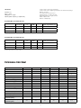
The following filters is used when TDS >500
Model
Tannin Removal
Capacity( ppm)
Resin Volume
(CF)
Flow Rate
(GPM)
Backwash
Sulphate Removal Capacity
(grains = mg/l divided by 17.1)
OCR15-850 SXT
3,000
1.5
3
1.2
10500
OCR20-850 SXT
4,000
2
4
2
14000
OCR30-850 SXT
6,000
3
6
2.4
21000
Needs to be regenerated every 2 (ideal) to 3 days
The following filters is used when TDS <500
Model
Tannin Removal
Capacity( ppm)
Resin Volume
(CF)
Flow Rate
(GPM)
Backwash
Sulphate Removal Capacity
(grains = mg/l divided by 17.1)
OCR15-860 SXT
3,000
1.5
3
1.2
10500
OCR20-860 SXT
4,000
2
4
2
14000
OCR30-860 SXT
6,000
3
6
2.4
21000
Needs to be regenerated every 2 (ideal) to 3 days
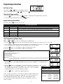
Performance Data Sheet
4924
4925
4926
4927
4928
4929
Model #
OCR15-850SXT
OCR20-850SXT
OCR30-850SXT
OCR15-860SXT
OCR20-860SXT
OCR30-860SXT
Tank Size
10 X 54
12 X 52
14 X 65
10 X 54
12 X 52
14 X 65
1.5
2
3
1.5
2
3
3,000
4,000
6,000
3,000
4,000
6,000
3
4
6
3
4
6
5
7
10
5
7
10
1.2
2
2.4
1.2
2
2.4
Unit Item #
Media (CF)
Capacity - 10 lbs of Salt/CF of Resin
Service Flow Rate (gpm)
Peak Service Flow Rate (gpm)
Backwash Flow Rate (gpm)
Injector
#00
#00
#0
#00
#00
#0
BLFC
0.25
0.25
0.5
0.25
0.25
0.5
Slow Rinse Flow Rate (gpm)
0.254
0.254
0.254
0.254
0.254
0.375
Brine Draw/Slow Rinse Time (minutes)
60
60
60
60
60
60
Backwash Time (minutes)
10
10
10
10
10
10
Rapid Rinse (minutes)
10
10
10
10
10
10
Brine Refill (minutes)
20
27
20
20
27
20
Total Time Consumed during
Regeneration (minutes)
100
107
100
100
107
100
Total Water Consumption during
Regeneration (gallons)
44.2
61.9
73.2
44.2
61.9
80.5
4
Specification
Unit †
Item #
Model #
Tank Size
Media (CF)
10 lbs of
Salt/CF of
Resin
Service
Flow Rate
(gpm)
Peak Service
Flow Rate
(gpm)
Backwash
Flow Rate
(gpm)
Brine Tank
Dimension (W X
D X H) Inches
Salt
Capacity
(lbs)
Shipping
Weight
(lbs)
4924
OCR15-850SXT
10 X 54
1.5
3,000
3
1.2
21 X 36
300
110
4925
OCR20-850SXT
12 X 52
2
4,000
4
4926
OCR30-850SXT
14 X 65
3
6,000
6
7
2
23 X 38
400
150
10
2.4
23 X 38
400
200
4927
OCR15-860SXT
10 X 54
1.5
3,000
3
5
1.2
21 X 36
300
110
4928
OCR20-860SXT
12 X 52
2
4,000
4
4929
OCR30-860SXT
14 X 65
3
6,000
6
7
2
23 X 38
400
150
10
2.4
23 X 38
400
200
Organic Color Removal Filters*
* Application must be based on analysis by an authorized
representative or distributor
Working Temperature = 34-110°F (1-43°C)
(Do not subject the unit to freezing temperatures)
Working Pressure = 20-125 PSIG (137-861 kPa)
Voltage = 120V / 60 Hz
Pipe Size = 3/4”
5
• At the stated service flow rates, the pressure drop through these devices will not exceed 15 psig.
• Changing salt settings from factory setting may require changing injector sizes to achieve stated capacities
• The manufacturer reserves the right to make product improvements which may deviate from the specifications and descriptions stated herein,
without obligation to change previously manufactured products or to note the change.
* Do not use water that is microbiologically unsafe without adequate disinfection before or after the system.
† USA customers will need to add “-4” to the item numbers for ordering.
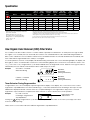
How Organic Color Removal (OCR) Filter Works
The OCR filter works like a water softener. It contains a bed of specially formulated resin. As water passes through the bed,
the organic color is held by the resin. Eventually the resin becomes saturated and must be cleaned and regenerated. A
brine solution is drawn into the resin bed to release the accumulated minerals. The minerals and brine are rinsed away with
fresh water and the regenerated resin is ready to work again.
In normal operation, the Time of Day display will alternate being viewed with the Volume Remaining display. This display will
be in gallons or liters. As treated water is used, the Volume Remaining display will count down from a maximum value to zero
or (---). Once this occurs, a regeneration cycle will be initiated at the Set Regeneration Time. Water flow through the valve is
indicated by the Flow Indicator that will flash in direct relationship to flow rate.
Example
833 Gallons of Treated
Water Remaining
PM Indicator
0 Gallons of Treated
Water Remaining
PM Indicator
Flow Indicator
(Flashing with water flow)
Flow Indicator
(Flashing with water flow)
Timer Behavior During Regeneration
In regeneration, the control will display a special regeneration display. In this display, the control will show the current
regeneration step abbreviation the valve is advancing to or has reached and the time remaining in that step. The step
abbreviation displayed will flash until the valve has completed driving into this regeneration step position. Once all
regeneration steps have been completed, the valve will return to Service and resume normal operation.
Example
Less than 6 minutes
remaining in Regeneration
Step Rapid Rinse
5
Regeneration Step
Abbreviation
Pushing the
during a regeneration cycle will immediately advance the valve to the next cycle step position and
resume normal step timing.
Please see the control valve manual for different regeneration step abbreviations.
5
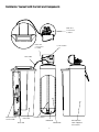
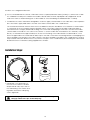
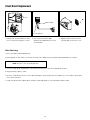
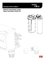
Familiarize Yourself with the Unit and Components
Drain Line
Connection
to Valve
Brine Line
Connection
to Valve
Control Valve
Brine Tube
Safety Float/Air
Check Inside
Brine Tank
Distributor/Riser
Underbed
Brine Well
Media Bed
6
Mineral/Resin
Tank wrapped
with Jacket
Installation Instructions
Contact your local distributor to use WaterGroup laboratory for complete water analysis free of cost and no
obligation to you.
All government codes and regulations governing the installation of these devices must be observed.
.
If the ground from the electrical panel or breaker box to the water meter or underground copper pipe is tied
to the copper water lines and these lines are cut during installation of the Noryl bypass valve and/or poly
pipe, an approved grounding strap must be used between the two lines that have been cut in order to maintain continuity. The length of the grounding strap will depend upon the number of units being installed and/or
the amount of copper pipe being replaced with plastic pipe. See Figure 1.
In all cases where metal pipe was originally used and is later interrupted by poly pipe or the Noryl bypass valve as in Figure
1 or by physical separation as in Figure 2, an approved ground clamp with no less than #6 copper conductor must be used
for continuity, to maintain proper metallic pipe bonding.
NOTE: Check your local electrical code for the correct clamp.
Figure 1
Hard
Filtered
Water
Electrical Panel
Cold Soft Water
Hard Soft Water
Ground Strap
Raw Water
To Outdoors
Drain
Drain
Water Meter
Filter
Organic Color Removal Filter
Figure 2
Unfiltered Water Bypass
Loop Cut & Capped
Ground Strap Required
Because of Break in Continuity
Filtered Water Line in Home
7
Water Heater
Preparations
1. Determine the best location for your water softener,
bearing in mind the location of your water supply lines,
drain line and 120 volt AC electrical outlet. Subjecting the
softener to freezing or temperatures above 43°C (110°F)
will void the warranty.
Hard
Filtered
Water
Electrical Panel
1
Hard Soft Water
Ground Strap
Raw
Water
Electrical
Outlet
To Outdoors
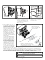
2. Media Installation (When Necessary). Models including
and higher than 1.5 CF of media are shipped with separate media in pails or boxes. Models lower than 1.5 CF of
media come loaded with media and this step can be
skipped for new installation.
Cold Soft Water
Drain
Drain
Water Meter
Drain
Filter
D
a
e
e
Plug
the
Riser
Tube
The riser
(distributor)
remains inside
the tank seated
in the depression
at the bottom
Organic Color
Removal Filter
Water Heater
C
B
b
a) Remove the valve from
the mineral tank.
b) Temporarily plug the open end
of the riser tube to ensure that no
resin or gravel falls down into the
distribution.
The riser (distributor) remains
inside the tank seated in the
depression at the bottom.
Plug tube with a tape.
Remove after media is loaded.
8
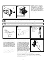
Fill support bed first. (if supplied)
The media will not always spill down
inside the tank and may need to be
swept inside.
Organic Color Removal
(OCR) Filter
d
The large funnel (sold separately part
# 43000) makes filling the tank easier
and neater. (Or an empty 1 gallon or 4
liter container with the bottom cut out
makes a good funnel.)
OCR Resin
(White)
f
O-ring
Support Bed
(when supplied)
Fine, Medium and/or
Course Gravel
c. F ill mineral tank one quarter full of
water to protect distribution during
gravel installation.
d. P
lace the media into the tank in the
order indicated above. Slowly and
carefully add the gravel support
bed and the softener or filtration
media leveling each layer as it is
placed into the tank.
e. Fill support bed (if supplied) first.
During the filling process, ensure the
distributor tube stays on the bottom
of the tank, reasonably centered.
Remove the tape from the distributor once media is loaded. Whenever
possible, fill the tank outdoors to
avoid problems with dust. If filling
indoors, a dust mask should be worn.
f
f. U
nplug the riser tube, carefully position the valve over it and turn the
valve into the threads in the fiberglass tank, tightening securely into
tank. Note: Ensure that the internal
O-ring in the valve fits securely over
the riser tube. Silicone grease (part #
92360) or other food grade lubricant
may be applied to the O-ring to
ease installation of the riser tube.
DO NOT use petroleum based lubricants as they will cause swelling of O-ring seals.
9
The filter is now charged with filter resin.
g. It is recommended that the softener or filter tank now be completely filled with water (SLOWLY) to soak the resin or filtration media before startup. This will allow the media to absorb water as well as help displace any trapped air. This will
reduce the chance of backwashing resin or filter media out of the tank during the initial backwash on startup.
3.Outside faucets used to water lawns and gardens should not supply softened water. A new water line is often required to
be connected to supply hard water to the inlet of the water softener and to the outside faucets.
Cut the water line between where it enters the house and before any lines that branch off to feed the hot water heater
or other fixtures in the house and as near the desired location of the water softener as possible. Install a tee fitting on
the feed end of the cut pipe, and an elbow fitting on the other end. Install piping from the tee to the inlet of the water
softener and from the elbow to the outlet of the softener. To sever the water lines which branch off to feed any outside
faucets, cut the branch lines approximately two inches from the fitting on the main water line. Install an elbow on the
end of the pipe nearest the outside faucet and a cap on the end connected to the existing water line. Install piping from
the tee installed on the inlet line to the water softener to the elbow installed on the pipe to the outside faucet. Following
this procedure will result in all lines in the house, with the exception of the outside faucets, but including the water heater
and therefore the hot water lines, being supplied with soft water.
Installation Steps:
1
1. C
lamp Ring – The clamp ring connects the control valve to the tank
and provide an easy way to disconnect tank during control valve servicing. Make sure that the clamp ring
screw is tightened.
The “Clamp Ring” should secure the valve with the top of the flange
facing up. Please note “top” on the clamp ring.
10
Timer Controls
Brine Line 3/8”
Extra Cycle
Button
Outlet
Inlet
2
Drain 1/2”
2. Familiarize yourself with the location
of the inlet, outlet and drain on the
control valve. Be very careful not to
get the controls wet.
4. Attach the bypass valve to the control valve (and yoke if plastic bypass
is used). Connect the inlet and outlet
of the water softener to the plumbing in the house. The control valve
must not be submitted to temperatures above 43°C (110°F). When
sweat fittings are used, to avoid
damaging the control valve, solder
the threaded copper adapters to
the copper pipe and then, using
Teflon tape, screw the assembly into
the bypass valve.
4
3
UP button
DOWN
button
3. Familiarize yourself with the buttons
on the timer control.
Make sure that the flow
meter is connected to the
outlet of the valve
OCR Filters are supplied with brass
Yoke
service line flow controls, similar to
the one shown in Figure 4. OCR15
size filters are supplied with #15177
flow control housing and 5.0 GPM
flow button with 3/4” x 1/2” FNPT
Bypass
connections. OCR20 size filters are
Flow
Directon
supplied with #15177 flow control
Install Flow control at the outlet of the
housing and 7.0 GPM flow button
valve. Note the arrow of the flow control
with 3/4” x 1/2” FNPT connections.
should point away from the valve
OCR30 size filters are supplied with
#019480 flow control housing and
10.0 GPM flow button with 3/4” x 3/4” FNPT connections. The
installation of this flow control ensure the recommended service flowrate of the OCR filter is not exceeded. If this flow
control is not installed, some colour may bleed through at higher flow rates. Thread the flow control onto the threaded
OUTLET of the bypass and yoke assembly. Only use teflon tape to seal the threads of the bypass and yoke assembly as
pipe thread compound may attack the material. Ensure the flow control indicates the direction of flow.
CAUTION! Check service line flow control direction of flow arrow and
only thread onto the service outlet line.
.
Do not use pipe thread compound as it may attack the material
in the valve body
.
11
5
Hose Barb
5. Drain Line Connection: Using teflon
tape, screw the 1/2” hose barb into
the drain port in the valve. Attach
1/2” drain hose to the hose barb and
tighten securely with a hose clamp.
Run the drain line to a floor drain or a
laundry drain. Complete any necessary plumbing.
5
Connect 1/2”
drain hose (not supplied)
with a hose clamp here
Waste connections or drain outlet shall be designed and constructed to provide for connection to the sanitary
waste system through an air-gap of 2 pipe diameters or 1 inch (22 mm) whichever is larger.
Never insert drain line directly into a drain, sewer line, or trap. Always allow an air gap between the drain line and
the wastewater to prevent the possibility of sewage being back-siphoned into the conditioner.
5
6
One end of the
6
brine tubing come
attached to the
safety float
assembly
Tube Insert
6. T he brine line is connected to the
safety float assembly of the brine
tank. Pull the 3/8” brine line through
the hole in the back of the brine
tank. Connect the brine line to the
fitting on the side of the valve using
the nut and ferrule. Tighten snugly.
Remove the nut from the brine line
of the valve and push the other end
of the brine tube inside it. Make sure
that the brass insert is snugged inside
the brine tubing. The brine tubing
should pass through both plastic
inserts of the black nut.
7. Overflow Connection (Optional): In
the event of a malfunction, the brine
TANK OVERFLOW will direct “overflow”
to the drain instead of spilling on the
floor. This fitting should be installed at
the side of the cabinet or brine tank.
6
Brine
Tubing
To connect the overflow line, drill
the hole on the side of the tank, 2 to
3 inches below from the top of the
brine tank. Insert overflow fitting (sold
separately part # 33006) into tank and
tighten with plastic thumb nut and
gasket as shown. Attach length of
1/2-inch (1.3-cm) I.D. tubing (not supplied) to fitting and run to drain. Do not
elevate overflow line higher than overflow fitting.
Do not tie into drain line of control unit. Overflow line must be a direct,
separate line from overflow fitting to drain, sewer or tub. Allow an air gap
as per drain line instructions.
12
7
8
9
Overflow Fitting
outlet
Drain Tubing
intlet
Secure hose in place
Air Gap
Drain
8. Make sure the bypass valve is in the
service position.
9. Plug the 24-volt transformer into a
120 VAC 60 Hz outlet.
10
Circuit Board Screen
Position Label
Brine
Valve
Brine Cam
10. This valve has four positions: 1) Brine/
Rinse 2) Backwash 3) Rapid Rinse
and 4) Brine Refill. When the valve
is in the Service position
must
be pressed and held for 5 seconds
before it activates. Press and hold
the
pic for 5 seconds to advance the valve into the “1” Brine/
Rinse position. Press once more to
advance to the “2” position.
The valve position during regeneration and servicing can be checked
in the circuit board screen as well
the position label on the cam.
13
Cycle Step
BD
BW
RR
BF
SV
Abbreviation
Brine Draw
Backwash
Rapid Rinse
Brine Refill
Service
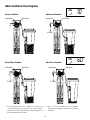
Water Conditioner Flow Diagrams
Service Position
Backwash Position
BW
Hard Water
Soft Water
Hard Water
Soft Water
Hard Water
Soft Water
Hard Water
Soft Water
To Drain
To Drain
To Drain
To Drain
BrineWater
Rinse
Hard
Hard Water
Position Soft Water
Slow
Rinse
Position
Hard
Water
Hard Water
Soft Water
To Drain
To Drain
To Drain
To Drain
Soft Water
60
Soft Water
12. Press once more to advance to the “3” Rapid
Rinse position and allow water to run to drain for
2Hard
Minutes.
Water
Soft Water
11. P
ress the extra cycle button to advance the valve to the
“2” Backwash position. Slowly turn on the water supply
Hard
Water
Soft Water
and
allow the unit to backwash
until the air purges out of
the tank and clears the system.
Hard Water
BD
10
Hard Water
Soft Water
14
Soft Water
RR
Rapid Rinse Position
Hard Water
BF
10
Brine Refill Position
Hard Water
Soft Water
To Drain
Soft Water
To Drain
13. Press once more to advance to the “4” Brine refill
position. Wait until the water level reaches 6” in
the brine tank. Water can be added to the tank to
speed up the filling but the valve should be in the
Brine Refill position for a minimum of two minutes to
purge the air out of the injector set.
14. Press
to advance the valve from the Brine Fill position through service to the “1” position Brine/
Rinse position. Verify that water is being drawn from the tank. If not, repeat step 9.
15. Press
button to advance the valve to the “2” Backwash position.
16. Press
to advance the valve to the “3” Rapid Rinse position.
17. Press
to advance the valve to the “4” Brine Fill position until there is 6” of water in the brine tank.
Press
to advance the valve back into the service position indicated by the
of the display.
15
in upper left corner
12
18. P
ut 40 kgs of crystal water softener
salt in the brine tank. The unit will
automatically fill the water to the
correct level when it regenerates.
19. Set time of the day in the control
valve and program the user section of the control. Refer to control
valve programming section in this
manual.
20. It is suggested that for the first
couple service/regeneration
cycles the colour of the water
should be closely monitored. If
colour begins to break through
prior to the calculated amount set,
the gallonage setting should be
reduced accordingly.
Optional Sanitization Procedure: We recommend that all new water conditioners be disinfected as
part of the startup.
Water Softener Sanitization
1a
Sanitization Solution
1a. P
our entire packet of Sani-System
Liquid Concentrate – Part # 50032
(24 packets) into the brine well. If
no brine well is present, pour entire
packet into bottom of brine tank
when salt is nearly empty.
1b
Press and Hold
to manually regenerate
1b. Manually regenerate the softener
according to the manufacturer’s
specifications.
Sanitization can also achieved by the application of chlorine in the regeneration cycle of the conditioner. A liquid solution
of 5.25% sodium hypochlorite (commonly referred to as household bleach) is recommended as a suitable disinfectant.
Use only unscented products. For every cubic foot of resin in the softener, pour approximately two (2) tablespoons of sodium hypochlorite into the brine well tube. The brine tank refill step of regeneration should add the correct amount of water
to the brine tank. If not, the water can be added manually now. Press and hold the
to begin a manual regeneration.
Allow softener to complete the Brine/Rinse cycle, then let the manual regeneration continue until the brine tank is refilled
again with the correct amount of water.
NOTE: ALL STATE AND LOCAL GOVERNMENT CODES GOVERNING INSTALLATION OF THESE DEVICES MUST BE OBSERVED.
16
Programming Instructions
Set Time of Day
Press and hold
or
buttons until display reads TD
Adjust the displayed time with
or
buttons. Press
to resume normal operation
Queuing a Regeneration
1. P
ress the
button. The service icon
will flash to indicate that a regeneration is queued.
2. T o cancel a queued regeneration, press the
button.
Regenerating Immediately
Press and hold the
button for five seconds.
User Programming Mode Options
Abbreviation
Parameter
DO
Day Override
Description
The timer’s day override setting
This is an option only. Please do not adjust before consulting an authorized dealer.
RT
Regeneration Time
The time of day that the system will regenerate (meter delayed, timeclock, and day-of-week systems)
H
Feed Water Hardness
RC
Reserve Capacity
CD
Current Day
The hardness of the inlet water - used to calculate system capacity for metered systems
OFF
The fixed reserve capacity
The current day of week
OFF
OFF
User Programming Mode Steps
Note: Use
1. Press the
and
and
Down button to adjust values for parameters
buttons for five seconds while in service, and the time of day is NOT set to 12:01 PM.
2. U
se this display to adjust the Day Override. Adjust this to OFF parameter for softeners. It should be
set to 3 if days between regeneration is calculated to be more than 3 days.
3. P
ress the
button. Use this display to adjust the Regeneration Time.
4. Press the
button. Use this display to adjust the Feed Water.
OFF
OFF
Tannin concentration of water in ppm. The capacity should also be calculated separately in order to determine the days between regeneration. If the days between regeneration is calculated more than
3 than day Override (DO) should be set to 3.
The frequency of automatic regeneration can be determined as follows
Capacity of your OCR Filter (See Specifications Page 1)
÷ ppm of tannins in water sample.
= No. of Gals. between regeneration
- Reserve (No. of people x 75 gals.)
= No. of Gals. at which to set the program wheel
Important Note : D
ue to the nature of the interaction between the colour producing organic molecules and the resin bed in your OCR filter, we recommend OCR filters be regenerated a minimum of
every 3 days. If the calculated capacity allows a service run longer than 3 days (on average) between regenerations, the set gallonage should be reduced accordingly. This is to
extend the life of the resin bed in your OCR filter.
5. P
ress the
button. Use this display to adjust the Fixed Reserve Capacity. This option setting is
identified by “RC” in the upper left-hand corner of the screen. 75 gallons X # of people in the
house = RC
6. P
ress the
button. Use this display to set the Current Day of the Week. This option setting is
identified by “CD” in the upper left hand corner of the screen. This option is
Regeneration Cycle Step Programming
only available after the Day of the Week control is set to ‘ON’ in the Master
1. Brine Rinse
60 minutes
Programming. Refer to the valve manual for details.
2. Backwash
10 minutes
7. Press the
button to end User Programming Mode.
3. Rapid Rinse 10 minutes
In the second level mode, the control valve has been programmed as per the
following main parameters related to regeneration. For more information on
master programming manual, read control valve manual part # 54802
The valve has been pre-programmed with factory settings as shown in the
chart to the right:
17
4. Brine Refill
20 minutes
27 minutes
20 minutes
20 minutes
27 minutes
20 minutes
OCR15-850SXT
OCR20-850SXT
OCR30-850SXT
OCR15-860SXT
OCR20-860SXT
OCR30-860SXT
Sizing Example
Suppose the raw water has the following amount of organic substances:
Sulfates – 350 mg/l
+Alkalinity - 500mg/l
+Tannin – 3.0 mg/l
Total of Sulfates and Alkalinity
= 850 ppm divided by 17.1 to convert to grains per gallon = 50gpg
Total of grains per gallon to dealt with
= 50gpg (Sulfates and Alkalinity) + 3.0gpg (Tannin) = 53gpg
Given an example of 4 people in a family, sizing would be as follows:
4 people X 60 gallons per day per person X 53 grains per gallon = 12720 grains
In a three day period, the grains to be removed will be = 12720 X 3 or 12720 X 3 / 17.1(to convert in ppm) = 2231 ppm
Utilizing your resin; 2000 ppm capacity per cubic foot.
Amount of resin required to deal with 2231 ppm of organic substances = 1.11 Cubic feet.
So we require a unit to have at least 1.5 cubic foot of resin.
The capacity of 1.5 cubic of resin = 2000 X 1.5 = 3000 ppm or 3000 X 17.1 grains per gallon
Total gallons of water capacity of the resin = 3000 X 17.1/ 53gpg = 967 gallons
One day water reserve for four people = 4 X 60 = 240
The unit needs to be set at 967-240 = 727 gallons between regeneration.
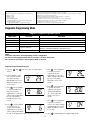
Diagnostic Programming Mode
Diagnostic Programming Mode Options
Abbreviation
Parameter
Description
FR
Flow Rate
Displays the current outlet flow rate
PF
Peak Flow Rate
Displays the highest flow rate measured since the last regeneration
HR
Hours in Service
Displays the total hours that the unit has been in service
VU
Volume Used
Displays the total volume of water treated by the unit
RC
Reserve Capacity
Displays the system’s reserve capacity calculated from the system
capacity, feed water hardness, and safety factor
SV
Software Version
Displays the software version installed on the controller
NOTES:
Some items may not be shown depending on timer configuration.
The timer will exit Diagnostic Mode after 60 seconds if no buttons are pressed.
Press the Extra Cycle button to exit Diagnostic Mode at any time.
Diagnostic Programming Mode Steps
1. Press the
service.
and
5. Press
. Use this display
to view the Volume
Used since the last
regeneration cycle. This
option setting is identified
by “VU” in the upper
left hand corner of the
screen.
buttons for five seconds while in
2. Use this display to view
the current Flow Rate.
This option setting is
identified by “FR” in the
upper left hand corner
of the screen.
6. Press
. Use this display
to view the Reserve
Capacity. This option
setting is identified by
“RC” in the upper left
hand corner of the
screen.
3. Press
. Use this display
to view the Peak Flow
Rate since the last
regeneration cycle. This
option setting is identified
by “PF” in the upper
left hand corner of the
screen.
7. Press
. Use this display
to view the Software
Version. This option setting
is identified by “SV” in the
upper left hand corner of
the screen.
4. Press
. Use this display
to view the Hours in
Service since the last
regeneration cycle. This
option setting is identified
by “HR” in the upper left hand corner of the screen.
8. Press
18
to end Diagnostic Programming Mode.
Controller Behavior
Control Operation During Programming
The control will only enter the Program Mode with the valve in Service. While in the Program Mode, the control will
continue to operate normally, monitoring water usage and keeping all displays up to date. Control programming is stored
in memory permanently, eliminating the need for battery back-up power.
Meter Immediate Control
A meter immediate control measures water usage and regenerates the system as soon as the calculated system capacity
is depleted. The control calculates the system capacity by dividing the unit capacity (typically expressed in grains/unit
volume) by the feedwater hardness and subtracting the reserve. Meter Immediate systems generally do not use a reserve
volume. However, in twin tank systems with soft-water regeneration, the reserve capacity should be set to the volume
of water used during regeneration to prevent hard water break-through. A Meter Immediate control will also start a
regeneration cycle at the programmed regeneration time if a number of days equal to the regeneration day override
pass before water usage depletes the calculated system capacity.
Meter Delayed Control
A Meter Delayed Control measures water usage and regenerates the system at the programmed regeneration time after
the calculated system capacity is depleted. As with Meter Immediate systems, the control calculates the system capacity
by dividing the unit capacity by the feedwater hardness and subtracting the reserve. The reserve should be set to insure
that the system delivers treated water between the time the system capacity is depleted and the actual regeneration
time. A Meter Delayed control will also start a regeneration cycle at the programmed regeneration time if a number of
days equal to the regeneration day override pass before water usage depletes the calculated system capacity.
Time Clock Delayed Control
A Time Clock Delayed Control regenerates the system on a timed interval. The control will initiate a regeneration cycle at
the programmed regeneration time when the number of days since the last regeneration equals the regeneration day
override value.
Day of the Week Control
This control regenerates the system on a weekly schedule. The schedule is defined in Master Programming by setting
each day to either “off” or “on.” The control will initiates a regeneration cycle on days that have been set to “on” at the
specified regeneration time.
Control Operation During a Power Failure
The SXT includes integral power backup. In the event of power failure, the control shifts into a power-saving mode. The
control stops monitoring water usage, and the display and motor shut down, but it continues to keep track of the time and
day for a minimum of 48 hours.
The system configuration settings are stored in a non-volatile memory and are stored indefinitely with or without line power.
The Time of Day flashes when there has been a power failure. Press any button to stop the Time of Day from flashing.
If power fails while the unit is in regeneration, the control will save the current valve position before it shuts down. When
power is restored, the control will resume the regeneration cycle from the point where power failed. Note that if power fails
during a regeneration cycle, the valve will remain in it’s current position until power is restored. The valve system should
include all required safety components to prevent overflows resulting from a power failure during regeneration.
The control will not start a new regeneration cycle without line power. If the valve misses a scheduled regeneration due to
a power failure, it will queue a regeneration. Once power is restored, the control will initiate a regeneration cycle the next
time that the Time of Day equals the programmed regeneration time. Typically, this means that the valve will regenerate
one day after it was originally scheduled. If the treated water output is important and power interruptions are expected,
the system should be setup with a sufficient reserve capacity to compensate for regeneration delays.
19
During Regeneration
Automatic Bypass
The regeneration cycle lasts approximately 2 hours, after which soft water service will be restored. During regeneration, hard
water is automatically bypassed for use in the household. Hot water should be used as little as possible during this time to
prevent hard water from filling the water heater.
IMPORTANT: This is why the automatic regeneration is set for sometime during the night and manual regenerations should be
performed when little or no water will be used in the household.
New Sounds
You may notice new sounds as your water softener operates. The regeneration cycle lasts approximately 2-1/2 hours. During
this time, you may hear water running intermittently to the drain.
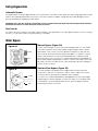
Water Bypass
Manual Bypass (Figure 5A)
Figure 5A
Outlet
Inlet
In case of an emergency such as an overflowing brine tank, you can isolate
your water softener from the water supply using the bypass valve located
at the back of the control. In normal operation the bypass is open with the
ON/OFF knobs in line with the INLET and OUTLET pipes. To isolate the softener,
simply rotate the knobs clockwise (as indicated by the word BYPASS and
arrow) until they lock. You can use your water related fixtures and appliances
as the water supply is bypassing the softener. However, the water you use will
be hard. To resume soft water service, open the bypass valve by rotating the
knobs counter-clockwise.
Stainless Steel Bypass (Figure 5B)
Figure 5B
In normal operation the bypass lever is aligned with the inlet/outlet with
the pointer on SERVICE. To isolate the softener or filter, rotate lever counter
clockwise until it stops and pointer indicates unit is in bypass.
Outlet
Inlet
You can use your water related fixtures and appliances as the water supply
is bypassing the softener and filter. However, the water you use will be hard
or untreated. To resume treated water service, open the bypass valve by
reversing the rotation of the lever.
20
Maintenance Instructions
Checking the Salt Level
Check the salt level monthly. Remove the lid from the cabinet or brine tank, make sure salt level is always above
the brine level
NOTE: You should not be able to see water
Adding Salt
Use only clean salt labeled for water conditioner use, such as crystal, pellet, nugget, button or solar.
The use of rock salt is discouraged because it contains insoluble silt and sand which build up in the brine tank and can
cause problems with the system’s operation.
Add the salt directly to the tank, filling no higher than the top of the brine well.
Bridging
Humidity or the wrong type of salt may create a cavity between the water and the salt.
This action, known as “bridging”, prevents the brine solution from being made, leading to
your water supply being hard.
If you suspect salt bridging, carefully pound on the outside of the plastic brine tank or pour
some warm water over the salt to break up the bridge. This should always be followed up
by allowing the unit to use up any remaining salt and then thoroughly cleaning out the
brine tank. Allow four hours to produce a brine solution, then manually regenerate the
softener.
CAUTION! Liquid brine will irritate eyes, skin and open wounds gently wash exposed area with fresh water. Keep children away from
your water conditioner.
Resin Cleaner
An approved resin cleaner must be used on a regular basis if your water supply contains iron. The amount of resin cleaner
and frequency of use is determined by the quantity of iron in your water (consult your local representative or follow the
directions on the resin cleaner package).
Iron Fouling Recommended Product: PRO RUST OUT – Clean iron from resin media bed with a reducing agent such
as sodium bisulfite or sodium hydrosulfite by adding it to the brine tank down the brine well and allowing time to mix.
Manually regenerate softener (see instructions on bottle on cleaning of water softeners).
Calcium Carbonate Recommended Product: PRO Res-Care – Clean calcium carbonate from resin media with a mild
acid solution such as phosphoric acid. Do this by adding cleaning product to the brine tank via the brine well and then
manually regenerate. Once complete, manually regenerate again with salt brine (see instructions on bottle on cleaning of
water softeners).
Care of Your Softener
To retain the attractive appearance of your new water softener, clean occasionally with a mild soap solution. Do not use
abrasive cleaners, ammonia or solvents. Never subject your softener to freezing or to temperatures above 43°C (110°F).
Servicing Components.
• T he injector assembly should be cleaned or replaced every year depending on the inlet water quality and water usage.
• The seals and spacer cartridge should be inspected/cleaned or replaced every year depending on the inlet water
quality and water usage.
Please refer to the servicing section of this manual for step by step procedure.
Not following the above will void all warranty on the control valve.
21
Res-Up® Feeder Installation Instructions
1. Remove top cover, fill the
Res-Up® Feeder (plastic
container) to the top with water
so that the wick retaining clip,
tube and wick are wetted, allow
to soak for 15 minutes or more.
Res-up Feeder
5/8" hole in Brine
Well Cap
2. Empty water and pull tube and
wick through Feeder until slack is
removed from inside. The outlet
end tube and wick must be
below the bottom level of the
Res-Up® Feeder.
3. Drill two 1/4” holes in brine tank
as shown.
1/4” Holes
4. Drill a 5/8” hole in the
brine well cap.
5. Clip mounting bracket over
feeder with “hooks” pointed up.
Insert end of tube in the brine well
cap and mounting bracket with
the 1/4” holes in the brine tank,
rotating feeder downward into
position as shown in Figure 1.
6. Fill Feeder with Res-Up® Cleaner
to “Fill Line” on label.
7. Replace cover on Feeder and
automatic feeding will occur in a
few hours.
Res-Up Feeders attach to your brine tank and automatically dispense the Res-Up cleaner into the brine solution where it
cleans the resin during the regeneration cycle.
The feeder hooks onto the tube inside your brine tank and you just pour some chemical in it and your water softener should
last significantly longer. A res-up feeder is essential if your raw water contains measurable amounts of iron.
Res-up Feeder Bottle (Chemical sold Separately)
The 12 cc feeder (Part # 33010) is for softeners up to 64,000 grains (2 ft3 or CF of resin) .
The 30 cc feeder (Part # 33018) is for larger softeners over 64,000 grains.
Pro-Res Care Chemicals
Item #45147 Pro-ResCare - Gallon
Item #45148 Pro-ResCare - Quart
22
Servicing 6200 Valve
Before Servicing
1. Turn off water supply to conditioner :
a. If the conditioner installation has a 3 valve bypass system first open the valve in the bypass line, then close the valves at
the conditioner inlet & outlet.
b. If the conditioner has an integral bypass valve, put it in the bypass position.
c. If there is only a shut-off valve near the conditioner inlet, close it.
2. R
elieve water pressure in the conditioner by stepping the control into the backwash position momentarily. Return the
control to the In Service position. (Refer to programming instructions)
3. Unplug Electrical Cord from outlet.
4. D
isconnect brine tube and drain line connections.
WARNING! E
LECTRICAL SHOCK HAZARD! UNPLUG THE UNIT BEFORE REMOVING THE COVER OR ACCESSING ANY
INTERNAL CONTROL PARTS.
CAUTION! Disassembly while under pressure can result in flooding. Always follow these steps prior
to servicing the valve.
23
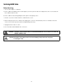
6200 Service Kits – Piston and Cartridge Assembly
O-Ring 97
O-Ring 98
Blank
7
6
5
1
2
3
4
REVISIONS
ECN
ZONE
REV.
DATE
DESCRIPTION
APP'D
100
D
Blank
101
C
Dwg #
Part #
Part Description
7
61799-01
Cartridge Assembly with Piston
76
11335
Screw, 4-40X3/16
97
16394
O-Ring, 029
98
13287
O-Ring, 123
99
61799
Seal and Spacer Cartridge
100
42920
Piston
101
19984
Piston Rod
76
B
LAST SAVED IN SMARTEAM:
LEVEL I
LEVEL II
DO NOT SCALE DRAWING. DIMS. ARE IN INCHES [mm]
INTERPRET DIMS AND TOLERANCES PER ASME Y14.5M -1994
UNLESS OTHERWISE SPECIFIED:
CORNER FILLETS R.005-.020 [.127-.508]
TOLERANCES:
ANGLES :
1
1 PLACE .X:
.015 [0.38]
2 PLACE .XX:
.01 [0.3]
3 PLACE .XXX:
.005 [0.13]
7
6
5
4
3
O-Ring 97
DATE AND TIME
CRITICALITY SYMBOLS PER QPSP-001.2
THIS DOCUMENT IS SOLELY THE PROPERTY OF PENTAIR
WATER TREATMENT. REPRODUCTION, USE DISCLOSURE, OR
TRANSMISSION OF THIS DOCUMENT OR DETAILS CONTAINED
HEREIN, IN PART OR IN WHOLE, IS PROHIBITED WITHOUT
THE WRITTEN CONSENT OF PENTAIR WATER TREATMENT
ENGINEERING. THIS DOCUMENT AND ANY COPIES SHALL BE
RETURNED TO PENTAIR WATER TREATMENT UPON WRITTEN
REQUEST.
LEVEL III
A
THE COMPONENT, PART, OR ASSEMBLY DESCRIBED IN THIS DOCUMENT MUST COMPLY WITH THE EU (EUROPEAN UNION) DIRECTIVE:
RoHS DIRECTIVE 2002/95/EC,
THIS DRAWING MUST BE COMPARED TO THE ERP SYSTEM TO ENSURE CORRECT REVISION LEVEL PRIOR TO USE.
THIRD ANGLE
PROJECTION
APPROVALS
DRAWN
CHECKED
APPROVED
2
DATE
Pentair Residential
Filtration
TITLE
SIZE
SCALE
D
1:1
DWG NO.
REV
_
SOLIDWORKS FORMAT
SHEET 4 OF 4
1
O-Ring 97
7
99
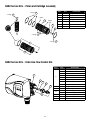
6200 Service Kits – Drain Line Flow Control Kits
Dwg #
19
61
61
62
63
88
12086
Washer, Flow, 1.50 GPM
12087
Washer, Flow, 2.0 GPM
12088
Washer, Flow, 2.4 GPM
12089
Washer, Flow, 3.0 GPM
12090
Washer, Flow, 3.5 GPM
12091
Washer, Flow, 4.0 GPM
12092
Washer, Flow, 5.0 GPM
11183
O-Ring, 017
63
11385-01
89
19
24
Part Description
Washer, Flow, 1.2 GPM
62
88
89
Part #
12085
13308
12388
Adapter, Fitting, DLFC
Hose Barb, Straight, DLFC,1/2"
Hose Barb, 90 Deg, DLFC,1/2"
60705-XX
DLFC Assembly, XX GPM For < 7 GPM
60706-XX
DLFC Assembly, XX GPM For > 7 GPM
18312
Retainer, Drain
6200 Service Kits – Brine Line Flow Control Kits
18
Dwg #
Part #
17
13302
O-Ring, 014
12
10141
O-Ring, 010
17307
Washer, Flow, 0.125 GPM
12094
Washer, Flow, 0.25 GPM
12095
Washer, Flow, 0.5 GPM
12097
Washer, Flow, 1.0 GPM
15
19334
Retainer, Flow Washer, BLFC
16
19335
Fitting, BLFC,3/8"
68
17
12
68
15
20
19625
95
60422-XX
Part Description
Nut, Assembly, 3/8" Plastic
BLFC Assembly, Specify XX=GPM
16
95
20
6200 Service Kits – Brine Valve
Dwg #
Part #
17
13302
O-Ring, 014
60032
Brine Valve Assembly
93
52
17
52
93
53
60
25
Part Description
40055-06 Bracket, Plastic
53
15137
Screw, Hex Washer Head
60
40134
Screw, Self Tap
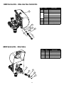
6200 Service Kits – Flow Meter
Dwg #
Part #
84
19791-01
22
19569
Clip, Flow Meter
84
24
22
Part Description
Cable, Meter
24
13314
Screw, Slot Hex, 8-18 X0.6
23
19797
Meter, Assy,3 /4" Dual Port
105
13305
O-Ring, -119
21
14613
Flow Straightener
94
60626
Meter Only, Electronic Turbine
21
23
94
105
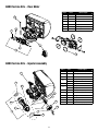
6200 Service Kits – Injector Assembly
91
Dwg #
Part #
91
18276-01
Plug, Injector, Assembly
64
040095
Flow Dispersor
40058
Screen, Injector
56
58
12
29
66
14
64
56
65
67
90
58
14
29
Replace with
91 for filter valve
13
26
Part Description
40079-20 Cap, Injector, Regulated, Softener
18277
Cap, Injector Filter
18262
Screw, #10-24 X 1
040064
Seal, Injector, Softener
18301
Seal, Injector, Filter
66
18275-X
Throat, Injector, Specify Size X
65
18274-X
Nozzle, Injector, Specify Size X
12
10141
O-Ring, -010
67
18273
Generator, Vortex
13
13771
O-Ring, -012
90
61514-XX
Injector Assembly, Specify Size XX
6200 Service Kits – Circuit Board
Dwg #
37
Part #
Part Description
82
19474-01
Harness, Power, SXT
84
19791-01
Cable Meter
36
42766-02
Circuit Board, SXT
37
17020
Screw
36
84
82
6200 Service Kits – Other Parts
Dwg #
17020
Screw, Stl Hex, 6-20 X 3/8
51
040050
Screw, Hex Washer
34
42919
Cam, Brine
43107
Label, Cam Position, Softener
43121
Label, Cam Position, Filter
24
13314
Screw, Slot, Hex, 8-18 X 0.60
87
18280
Collector, Top, 1"
48
19619
Bracket, Idler
47
43298
Gear Idler
42
10218
Switch, Micro
51
34
42
85
47
24
87
48
27
Part Description
37
85
37
Part #
6200 Service Kits – Other Parts Continued
35
49
40
54
Dwg #
40
41
31
43
55
37
32
Part #
Part Description
43052-01
Cover, Black
43052-02
Cover, Cream
54
10231
Screw, Slot Hex, 1/4-20 X 1/2
49
19597
Motor, 24V, 50/60 Hz
43053-01
Backplate, Black
35
43053-02
Backplate, Cream
41
19581
Bracket, Drive
43
10302
Insulator, Limit Switch
32
019688
Link, Piston Rod
31
019493
Shaft, Drive
55
13363
Washer
37
17020
Screw, Hex, 6-20 X 3/8
Dwg #
Part #
28
19998
Part Description
Shaft, Drive
27
40057
Screw, Hex Washer Head
26
40254
Clamp, Ring
92
60503
Clamp Ring Assembly
26
27
28
92
28
Bypass Valve Assembly & Yokes (Plastic)
Item No.
Quantity
Part No.
Description
1
2
13305
O-ring, -119
2
2
13255
Clip, Mounting
3
2
13314
Screw, Hex Washer Head, 8-18 x 5/8
4A
1
18706
Yoke, Plastic, 1” NPT
4B
1
18706-02 Yoke, Plastic, 3/4” NPT
13708
13708NP
13398
13398NP
40636
Yoke, Brass, 3/4” NPT
Yoke, 3/4” NPT Nickel Plated
Yoke, Brass, 1” NPT
Yoke, 1” NPT Nickel Plated
Yoke, 1 1/4” NPT
40636-49 Yoke, 1 1/4” Sweat
2310 Safety Brine Valve
Item No.
Quantity
Part No.
Description
1
1
19645
Body, Safety Brine Valve, 2310
2
1
19803
Safety Brine Valve Assembly
3
1
19804
Screw, Socket Hd, Set, 10-24 X .75
4
1
19805
Poppet Assembly, SBV w/O-ring
5
1
19652-01
3RSSHW $VV\, 6%9 Z/2-ULQJ
6
1
19649
Flow Dispenser
7
1
11183
O-ring, -017
8
1
19647
Elbow, Safety Brine Valve
9
2
19625
Nut Assembly, 3/8” Plastic
10
1
18312
Retainer, Drain
11
1
60014
Safety Brine Valve Assembly, 2310
12
2
10150
Grommet, .30 Diameter
13
1
60068-30
Float Assembly, 2310, w/30” Rod
14
1
60002-34
Air Check, #500, 34” Long
29
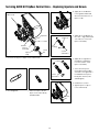
Servicing 6200 SXT Upflow Control Valve – Replacing Injectors and Screen
4.Apply silicone lubricant
to the gasket and install
around oval extension on
injector cap.
Valve Body
Disperser
Disperser
Screen
Gasket
Injector
Assembly
5.Apply silicone lubricant to
two new o-rings and install
over 2 bosses of the new
injector assembly.
Two
O-Rings
Screw
Vortex
Generator
Injector
Cap
1. Unscrew the injector cap from the valve body.
6.Apply silicone grease to
the dispersor and press
it on the surface of the
injector assembly.
Disperser
7.Screw in new injector
throat and nozzle (make
sure that vortex generator
is installed in the injector
body), be sure they are
seated tightly.
Vortex
Generator
8. Install a new screen.
9.Tighten injector cap on
to the valve body.
2. Discard gasket.
3.Remove injector assembly from the valve body
and discard it.
Screen
30
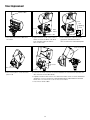
Replacing Brine Valve
Front Cover
1.Open the front cover of the powerhead, unscrew the
brine cam and push the brine valve in order to remove
the cam.
2.Remove the two screws from the grey brine valve bracket
and remove it from the valve back plate.
3.Pull brine valve from injector body. Also remove and
discard o-ring at bottom of brine valve hole.
4.Apply silicone lubricant to new o-ring and install at
bottom of brine valve hole.
5.Apply silicone lubricant to o-ring on new valve assembly
and press into brine valve hole. Be sure shoulder on
bushing is flush with injector body.
6.Reinstall the brine valve bracket. Make sure to use self
tapping screw at the bottom of the bracket. Reinstall
brine cam. Close the front cover of the control valve.
Brine Cam
Brine Valve
Screw
Bracket
Screw
Self tapping screw
Brine Valve
O-ring
31
Timer Replacement
Meter Cable
Screw
Self
tapping
screw
Screw
Brine
Valve
Brine Cam
1.Disconnect the meter cable from
the meter.
2.Open the front cover of the control
valve, unscrew the brine cam and
push the brine valve in order to
remove the cam.
Bracket
3.Remove the two screws from the
grey brine valve bracket and
remove it from the valve back plate.
Timer Assembly
Screw
Piston screw
4.Remove the piston screw from the
piston rod.
Screw
5.Remove the three screws from the front bracket. The entire timer assembly will
disconnect from the valve body.
6.Replace the timer with a new one. Attach the three screws to the front bracket
and piston screw to the piston rod. Reinstall the brine valve bracket. Reinstall
brine cam. Close the front cover of the control valve.
7. Reconnect meter cable.
32
Piston Cartridge Assembly Replacement
7
8
6
5
3
4
All 5 O-rings need to be
inspected for damages
and lubricated
1
2
REVISIONS
ECN
ZONE
D
REV.
DATE
DESCRIPTION
APP'D
D
C
C
B
B
DATE AND TIME
LAST SAVED IN SMARTEAM:
A
CRITICALITY SYMBOLS PER QPSP-001.2
LEVEL I
LEVEL II
THIS DOCUMENT IS SOLELY THE PROPERTY OF PENTAIR
WATER TREATMENT. REPRODUCTION, USE DISCLOSURE, OR
TRANSMISSION OF THIS DOCUMENT OR DETAILS CONTAINED
HEREIN, IN PART OR IN WHOLE, IS PROHIBITED WITHOUT
THE WRITTEN CONSENT OF PENTAIR WATER TREATMENT
ENGINEERING. THIS DOCUMENT AND ANY COPIES SHALL BE
RETURNED TO PENTAIR WATER TREATMENT UPON WRITTEN
REQUEST.
DO NOT SCALE DRAWING. DIMS. ARE IN INCHES [mm]
INTERPRET DIMS AND TOLERANCES PER ASME Y14.5M -1994
UNLESS OTHERWISE SPECIFIED:
CORNER FILLETS R.005-.020 [.127-.508]
TOLERANCES:
ANGLES :
1
1 PLACE .X:
.015 [0.38]
2 PLACE .XX:
.01 [0.3]
3 PLACE .XXX:
.005 [0.13]
BR42889
8
7
6
5
4
3
LEVEL III
A
THE COMPONENT, PART, OR ASSEMBLY DESCRIBED IN THIS DOCUMENT MUST COMPLY WITH THE EU (EUROPEAN UNION) DIRECTIVE:
RoHS DIRECTIVE 2002/95/EC,
THIS DRAWING MUST BE COMPARED TO THE ERP SYSTEM TO ENSURE CORRECT REVISION LEVEL PRIOR TO USE.
THIRD ANGLE
PROJECTION
APPROVALS
DRAWN
CHECKED
APPROVED
DATE
Pentair Residential
Filtration
TITLE
SIZE
SCALE
D
1:1
DWG NO.
REV
_
SOLIDWORKS FORMAT
2
SHEET 4 OF 4
1
This O-ring goes to the
bottom of the cartridge
Cartridge Assembly
1.Follow steps 1 to 5 of timer
replacement.
2.Use a flat head screw drive on the
notch of the valve body as shown
to loosen the piston cartridge, pull
the cartridge out of the body using
pliers.
3.Inspect the inside of the valve to
make sure that there is no foreign
matter that would interfere with the
valve operation.
4.Put food grade silicone grease on
the o-rings of the new piston cartridge assembly and install it inside
the valve body.
5.Reinstall the timer assembly, brine
valve bracket and meter cable.
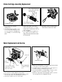
Meter Replacement and Service
Meter Cable
Outlet Port
Lubricate O-rings
Meter
Assembly
Clip
Flow Meter should be
attached to the outlet
side of the valve
Screw
4.Apply silicone lubricant to four new o-rings and assemble
to four ports on new meter module.
5.Assemble meter to control valve. Note, meter portion of
module must be assembled at valve outlet.
6.Push resin tank back to the plumbing connections and
engage meter ports with bypass valve or yoke.
7.Attach two clips and screws at bypass valve or yoke. Be
sure clip legs are firmly engaged with lugs.
Flow Straightainer
Inside the Outlet
Port
1.Disconnect the meter cable from the meter.
2.Remove two screws and clips at bypass valve or yoke.
Pull resin tank away from plumbing connections.
3.Pull meter module out from control valve.
33
Servicing and Replacing Brine Line Flow Control (BLFC)
1.Disconnect the brine line
retainer clip.
2.Remove the BLFC assembly and pull
the flow washer retainer out of the
BLFC housing with the help of plier.
3.Remove the flow washer from the
retainer and clean it with water to
remove any debris. Replace it with a
new washer if necessary.
4.Re-install the BLFC housing
and retainer.
Servicing and Replacing Drain Line Flow Control (DLFC)
1. Disconnect the drain line retainer clip.
2.Remove the DLFC assembly and pull the flow washer out
of the DLFC housing with the help of plier.
3.Remove the flow washer from the housing and clean it
with water to remove any debris. Replace it with a new
washer if necessary.
4. Re-install the DLFC housing and retainer.
DLFC
Retainer
Flow Washer
Housing
Flow Washer
Hose
Barb
34
Circuit Board Replacement
Screws
Meter Cable
Power Harness
1.Detach the circuit board from valve
front cover by removing two screws.
2.Disconnect the meter cable
and power head harness from the
circuit board.
3.Replace and connect the new
circuit board on the front cover.
After Servicing
1. Reconnect brine tube and drain line.
2. Return bypass or inlet valve to normal in service position. Water Pressure will automatically build in the softener.
NOTE: Be sure to shut off any bypass line.
3. Check for leaks at all sealed areas. Check Drain seal with the control in the backwash position.
4. Plug electrical cord into outlet.
5. Set Time of Day and cycle the control valve manually to assure proper function. Make sure control valve is returned to
the In Service position.
6. Verify the salt level in the brine tank is sufficient. Start regeneration cycle manually if water is hard.
35
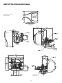
6200 SXT Valve Dimensional Drawings
All dimensions are in
Inches (mm).
36
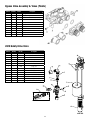
Parts Breakdown - Twin Tank
10
2
7
6
12
1
Common Components
Item No.
6
10
11
Part No.
48004
60626
60049
Description
Brine Well Cap
Meter
Bypass
Part
Number
Model
Description
Distributor
(1)
4924
OCR15-850SXT
19477
Valve
(2)
5
Tank
(3)
6200311 110541
Brine Tank
(4)
Grid
(5)
100362
4
8
3
Safety Float
(7)
Resin
Gravel
(#22001)
Inlet Flow Control (Housing
and Flow Washer)
13623
1.25 CF
0.08 CF
15177 (12091)
4925
OCR20-850SXT
19477
6200312 112521
100192
95009-21
13623
2.00 CF
0.12 CF
15177 (12408)
4926
OCR30-850SXT
60098
6200313 114651
100192
19706
13526
3.00 CF
0.15 CF
019480 (16529)
4927
OCR15-860SXT
19477
6200311 110541
100362
13623
1.25 CF
0.08 CF
15177 (12091)
4928
OCR20-860SXT
19477
6200312 112521
100192
95009-21
13623
2.00 CF
0.12 CF
15177 (12408)
4929
OCR30-860SXT
60098
6200313 114651
100192
19706
13526
3.00 CF
0.15 CF
019480 (16529)
4924, 4925 & 4926 use Resin #21494
4927, 4928 and 4929 use Resin #21491
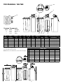
Dimesions (inches)
Note: All USA units come standard with #60040SS - Stainless Steel Bypass
G
B
C
A
OCR15-850SXT
OCR20-850SXT
OCR30-850SXT
36
OCR15-860SXT
OCR20-860SXT
OCR30-860SXT
38
38
36
38
38
B
21
22
22
21
22
22
C
10
12
14
10
12
14
D
61
59
72
61
59
72
E
19
19
19
19
19
19
F
56
54
67
56
54
67
G
2
2
2
2
2
2
E
D
F
A
37
Error Codes
Note: Error codes appear on the In Service display
Error Code
Probable Cause
Recover and Resetting
[Err 0]
Drive motor is stalled
Unplug the unit from the power source
[Err 1]
Drive motor is running continuously
When power is restored to the unit, the Err _ display
code clears. If the condition causing the error has
not been resolved the Err _ code reappears in the
four digit display. Do not attempt to troubleshoot this
problem any further.
[Err 2]
There have been more than 99 days since
the last Regeneration. If the Day of the Week
mode of regeneration is selected and days
since last regeneration exceeds 7 days.
Regeneration must occur for the unit to recover, the
display to clear and the valve to
function normally.
[ 7 - - 5 ]: There have been more than 7 days
since the last regeneration. All individual
settings (d1, d2, d3, d4, d5, d6, d7) are set to
0.
[Err 3]
Control board memory failure.
[ 7 - - 5 ]: To recover from [Err2], the user must
initiate a regeneration or set at least one individual
day to 1.
Perform a Master Reset. If the error returns,
do not attempt to troubleshoot this problem any
further.
Error Display Example
NOTE: Unit will flash when an error exists.
38
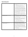
Trouble Shooting Guide
Problem: Fishy or unpleasant odour is apparent in the treated water that is not present in the untreated water.
1.
pH of the incoming water may be high.
2.pH of the incoming water maybe high in combination with
chlorine present for disinfection.
•
T his odour may be apparent on startup and will typically
be reduced or eliminated after a couple service runs and
regenerations cycles of the OCR filter.
•
T he addition of chlorine along with high pH typically increases
the chances that an odour will be present in the treated
water With the presence of chlorine, it is unlikely odour will be
eliminated. Chlorine can be removed through the use of an
activated carbon filter, however it is highly recommended
that additional disinfection methods be re-employed
downstream of the OCR filter with Ultraviolet Sterilizers or
Chlorination Pumps
Problem: O
CR unit was removing colour from water, but then starts to show colour again until regeneration.
Then colour is removed again.
1.Capacity of OCR unit is being overrun and resulting in tannins
not being removed near the end of service run.
• D
ecrease the gallons between service runs to a point where
no coloured water is appearing between one regeneration
to the next.
Problem: OCR unit was removing colour from water, but then starts to show colour earlier and earlier into service run.
OR
Problem: OCR unit was removing colour from water, but no longer seems to be effective.
1.
Regeneration is not being performed adequately.
•
•
•
2.
Regeneration is not being performed at all.
•
•
•
3.
Resin Media may be backwashing to drain.
•
•
4. OCR unit resin media may be fouled with organics. Check
resin visually to confirm.
•
39
heck to see if salt is in brine tank. If no salt is present, last
C
regeneration(s) may have been done without salt brine. Add
salt to brine tank and manually regenerate OCR until after
allowing brine to dilute in water for at least four (4) hours.
Check to see if brine tank is being refilled with water properly
at the end of the regeneration cycle and/or if water is being
drawn into the valve during the brine draw cycle. Injector &
Screen or Brine Valve may be plugged and require cleaning.
Check to see that valve settings are correct.
heck gallonage setting between regenerations. Capacity
C
set may be too large.
Check to see that meter is turning and properly connected
via the meter cable to the timer.
Check to ensure that Bypass Valve is not open and bypassing
the OCR unit with untreated water.
onfirm backwash flow control is installed on drain line and
C
check that backwash flow control has not been swapped for
service line flow control.
Monitor drain line during regeneration cycle and check that
no resin beads are exiting the OCR unit.
T ry manually regenerating OCR unit two or three times
in a row. Allowing approximately four (4) hours between
regenerations to allow salt brine to be saturated.
Trouble Shooting Guide
•
•
•
5.OCR filter resin media may be fouled with Iron.
Check visually to confirm.
•
•
•
6.OCR filter resin media may be fouled
with Calcium Carbonate.
•
•
40
dd small amount of Soda Ash to the brine well. Allow time
A
to mix with saturated brine solution and perform a manual
regeneration.
Recommended Product: PRO SODA ASH — see instructions
for cleaning tannin water softeners on bottle.)
As a last resort, try adding approximately four (4) ounces
of household bleach (5.25%) into the brine well. Begin a
manual regeneration. Monitor the drain line for a strong
chlorine odour which should occur in the brine draw cycle
. When odour is present, halt regeneration by unplugging
unit and shutting down water flow to the OCR unit via the
bypass valve. Shutdown OCR unit for approximately two (2)
hours, then continue regeneration by plugging unit back in
and replacing bypass valve to service position. Only try this
step as a last resort as chlorine will degrade the resin bed. If
unsuccessful, see next step.
Resin bed may have become permanently fouled due to
infrequency of regenerations or nature oftannins causing
colour in water. Replace resin media bed and check to see
that regeneration frequency is adequate or consult your
dealer.
Iron should typically be removed prior to the OCR unit. Install
an iron filter upstream of OCR unit or if small amounts of iron
are being removed with a softener, check to see that water
softener is working correctly.
Clean iron from resin media bed with a reducing agent such
as sodium bisulfite or sodium hydrosulfite by adding it to the
brine tank down the brine well and allowing time to mix.
Manually regenerate softener.
Recommended Product: PRO RUST OUT — see instructions
on bottle on cleaning of water softeners.
If resin bed cannot be cleaned, it may be permanently
fouled with iron. Replace resin media bed and install
treatment upstream of OCR unit to remove iron.
alcium Carbonate fouling is the result of hardness
C
precipitating onto the resin media. If a softener is installed,
check to see that it is functioning properly. If no water
softener is installed, have a water analysis done to confirm
hardness and install water softener upstream of OCR unit.
Clean calcium carbonate from resin media with a mild
acid solution such as phosphoric acid. Do this by adding
cleaning product to the brine tank via the brine well and then
manually regenerate. Once complete, manually regenerate
again with salt brine.
Recommended Product: PRO Res-Care — see instructions
on bottle on cleaning of water softeners.
Trouble Shooting Guide
Problem: OCR unit appear to be causing a high pressure drop in home water system.
1.
Pressure drop may be due other factors.
•
•
•
onfirm pressure loss is due to the OCR unit, and not the result
C
of distribution or well pump problem.
Confirm pressure loss is due to OCR unit by checking flow
while in BYPASS mode.
Check that flow demand is not exceeding rated
flow rate of OCR unit. OCR units are supplied with a
SERVICE LINE FLOW CONTROL to ensure maximum
effectiveness is maintained. Attempting to exceed this flow
control rating will result in a pressure drop. OCR unit should be
increased in size to compensate for larger demand.
NOTE: Do not remove this FLOW CONTROL from valve outlet.
It will likely result in a decrease in OCR unit performance.
2.Pressure loss may be due to fouling from Organics, Iron or
Calcium Carbonate.
•
S ee troubleshooting notes above on dealing with fouling
problems.
3.Pressure loss may be due to Resin Media being plugged with
•
Try manually regenerating OCR unit and extending the
Silt and Turbidity.
•
backwash by unplugging unit during the first cycle that
begins to send water to the drain. Monitor water to the drain
and watch for dirt and silt. If present, continue this backwash
cycle until water runs clear then plug unit and allow valve to
finish regeneration normally.
Install multi-media filter or 5 micron cartridge filter ahead of
OCR unit to remove Silt and Turbidity.
Problem: OCR unit appears to be removing most of the colour in the water, but some still passes through.
1.Raw water may be partially slipping past OCR unit
OR the Organics (Tannins) not being removed may be
impervious to the resin media in the OCR unit.
•
•
•
•
41
heck to see that SERVICE LINE FLOW CONTROL is in place
C
on the valve outlet. Flowrates higher than recommended
through the OCR unit may be causing some leakage of
colour.
Check to see that BYPASS valve is not partially open and
bleeding some raw water to distribution lines.
Check that pipelines after OCR unit are not lined with
organics that are slowly being stripped away. Lines may
require flushing.
If all equipment and distribution sources of problem have
been eliminated, consult your water treatment dealer, who
may try to “polish” the remaining colour after the OCR unit
with an ACTIVATED CARBON filter or cartridges or other
treatment method.
WaterGroup Guarantee
WaterGroup Inc. guarantees that your new water conditioner is built of quality material and workmanship.
When properly installed and maintained, it will give years of trouble free service.
Seven Year Complete Parts Guarantee:
WaterGroup Inc. will replace any part which fails within 60 months from date of manufacture, as indicated
by the serial number provided the failure is due to a defect in material or workmanship. The only exception
shall be when proof of purchase or installation is provided and then the warranty period shall be from the date
thereof.
Ten Year Guarantee on Mineral Tanks and Brine Tanks:
WaterGroup Inc. will provide a replacement mineral tank or brine tank to any original equipment purchaser in
possession of a tank that fails within 120 months, provided that the water conditioner is at all times operated in
accordance with specifications and not subject to freezing.
General Provisions:
WaterGroup Inc. assumes no responsibility for consequential damage, labor or expense incurred as a result of
a defect or for failure to meet the terms of these guarantees because of circumstances beyond its control.
U.S. Headquarters
WaterGroup Companies, Inc.
193 Osborne Road
Fridley, MN 55432, USA
Toll Free Phone: 1-877-581-1833
Canada Headquarters
WaterGroup Companies, Inc.
490 Pinebush Road, Unit 1
Cambridge, ON N1T 0A5, Canada
Toll Free Phone: 1-877-288-9888
www.watergroup.com
Distribution Locations
Durham, NC
Libertyville, IL
Pottstown, PA
Rancho Cucamonga, CA
Cambridge, ON
Calgary, AB
Regina, SK
52315.0512
Printed in Canada