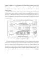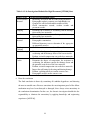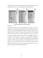
1
Technical Report Documentation Page
1. Report No.
2. Government Accession No.
3. Recipient's Catalog No.
SWUTC/02/167203-1
4. Title and Subtitle
5. Report Date
IMPLEMENTATION OF A DATABASE AND INFORMATION
SYSTEM FOR FORENSIC INVESTIGATION OF PAVEMENTS
September 2002
7. Author(s)
8. Performing Organization Report No.
Zhanmin Zhang and Chunrong Zhou
Research Report 167203-1
9. Performing Organization Name and Address
10. Work Unit No. (TRAIS)
Center for Transportation Research
University of Texas at Austin
3208 Red River, Suite 200
Austin, Texas 78705-2650
11. Contract or Grant No.
12. Sponsoring Agency Name and Address
13. Type of Report and Period Covered
6. Performing Organization Code
10727
Southwest Region University Transportation Center
Texas Transportation Institute
Texas A&M University System
College Station, Texas 77843-3135
14. Sponsoring Agency Code
15. Supplementary Notes
Supported by general revenues from the State of Texas
16. Abstract
This report describes the implementation of a database and information system for forensic
investigation of pavements by enhancing the 1998 version of the ForenSys database software. The
enhanced ForenSys database software can serve as the center component of an integrated forensic
information and analysis system for analyzing forensic related data and information and producing
forensic reports. In the study, a literature review on the basic concept and current practice of forensic
engineering has been performed; the system design concept of the relational database has been applied;
the 1998 version of the ForenSys database software has been improved; the guidelines of using the
ForenSys software have been developed; and a computerized procedure for automatically importing
PMIS data and Layer data to the ForenSys database has been developed.
17. Key Words
18. Distribution Statement
Forensic Investigation, Database, Information
Systems, Pavement Management Systems
No restrictions. This document is available to the
public through NTIS:
National Technical Information Service
5285 Port Royal Road
Springfield, Virginia 22161
19. Security Classif.(of this report)
20. Security Classif.(of this page)
21. No. of Pages
Unclassified
Unclassified
106
Form DOT F 1700.7 (8-72)
Reproduction of completed page authorized
22. Price
IMPLEMENTATION OF A DATABASE AND INFORMATION SYSTEM
FOR FORENSIC INVESTIGATION OF PAVEMENTS
by
Zhanmin Zhang
Chunrong Zhou
Research Report SWUTC/02/167203-1
SOUTHWEST REGION UNIVERSITY TRANSPORTATION CENTER
Center for Transportation Research
The University of Texas at Austin
Austin, Texas 78712
September 2002
DISCLAIMER
The contents of this report reflect the views of the authors, who are responsible for the
facts and the accuracy of the information presented herein. This document is disseminated under
the sponsorship of the Department of Transportation, University Transportation Centers
Program, in the interest of information exchange. The U.S. Government assumes no liability for
the contents or use thereof. Mention of trade names or commercial products does not constitute
endorsement or recommendation for use.
iii
ABSTRACT
This report describes the implementation of a database and information system for
forensic investigation of pavements by enhancing the 1998 version of the ForenSys database
software. The enhanced ForenSys database software can serve as the center component of an
integrated forensic information and analysis system for analyzing forensic related data and
information and producing forensic reports. In the study, a literature review on the basic
concept and current practice of forensic engineering has been performed; the system design
concept of the relational database has been applied; the 1998 version of the ForenSys database
software has been improved; the guidelines of using the ForenSys software have been
developed; and a computerized procedure for automatically importing PMIS data and Layer
data to the ForenSys database has been developed.
iv
ACKNOWLEDGMENTS
The authors recognize that support for this research was provided by a grant from the
U.S. Department of Transportation, University Transportation Centers Program to the Southwest
Region University Transportation Center which is funded 50 percent with general revenue funds
from the State of Texas.
v
EXECUTIVE SUMMARY
1.
BACKGROUND
Pavement forensic engineering is an essential part of the integrated pavement
management process. The forensic investigation can help pavement engineers determine the
cause of the premature failures of pavements, develop the rehabilitation strategies and improve
the future design and construction.
Forensic engineering synthesizes the art and the science of engineering to investigate the
causes of failures. It deals with the knowledge of many fields including mathematics, statistics,
structure engineering, dynamic mechanics, corrosion chemistry, hydraulics, soil mechanics and
infrastructure management [Noon 92]. A comprehensive definition of forensic engineering has
been provided by Milton F. Lunch, former General Counsel to the National Society of
Professional Engineers: “Forensic engineering is the application of the art and science of
engineering in the jurisprudence system, requiring the services of legally qualified professional
engineers. Forensic engineering may include investigation of the physical causes of accidents and
other sources of claims and litigation, preparation of engineering reports, testimony at hearings
and trials in administrative or judicial proceedings, and the rendition of advisory opinions to
assist the resolution of disputes affecting life or property” [Carper 89].
From the definition, it can be seen that compared to other engineering fields, forensic
engineering has some special characteristics. Having a comprehensive realization of these special
characteristics is very important for a forensic engineer to perform his or her task effectively and
efficiently. The following is a list of the main attributes of forensic engineering:
1.
Forensic engineering does not deal with the proposed infrastructure but with the
existing infrastructure that has premature failures.
2.
The task of forensic engineering is not planning, design or construction but the
investigation of the causes of failures.
3.
Forensic engineering always involves legal problems. Forensic engineers solve the
problems not only in technology and engineering fields but are also involved in
dispute resolutions. One of the primary objectives of forensic engineering is to
determine the responsibility of the failure. The report of the forensic investigation is
often used as proof in the court.
vii
4.
Forensic engineers usually face urgent deadlines to fulfill their tasks. The problem
recognition step and the field data collection step should be performed as soon as
possible, for example debris should be removed in time to prevent the blocking of
traffic from causing further danger. Also, meeting the deadline on a report may be
critical in jury deliberations and verdict outcomes.
5.
Forensic engineering always includes uncertainty. The final conclusion of the
forensic investigation may be drawn on the basis of insufficient information.
Sometimes the most important proof of the failure mechanism may have been
destroyed or damaged. In that case, the forensic investigators should take the
responsibility to eliminate the uncertainty by applying their knowledge and
engineering experience [ASCE 86].
2.
CURRENT FORENSIC ANALYSIS PRACTICE IN TxDOT
The Center for Transportation Research (CTR) Research Report 1731-1 entitled, “Basic
Concepts, Current Practices, and Available Resources for Forensic Investigations on Pavement,”
summarizes a comprehensive overview on the current practice of forensic investigation in the
Texas Department of Transportation (TxDOT) by reviewing part of the forensic investigation
reports prepared by TxDOT in the past 6 years and the TxDOT Department Circular #19-93,
which outlines the forensic practices within the state.
The report indicates that because the forensic investigation is affected by many various
factors, TxDOT currently conducts forensic engineering investigations on a case-by-case basis
without having a formal investigation procedure. Although the investigations are conducted on a
case-by-case basis, some common steps do exist in the investigation methodology. These steps
are investigation request, preliminary meetings between the project coordinator and the
investigation team, interviews with people who are familiar with the failure work, onsite
investigation, review of project records, detailed condition survey, materials sampling and
laboratory testing, analysis of data and identification of the most likely cause of the problem, and
production of a final report that documents the entire forensic investigation process in detail
[Victorine 97].
Report 1731-1 introduces these common investigation steps in detail. The following is a
summation of the information retrieved from the report. In the investigation request step, the
viii
district or division submits a memorandum to the Director of the Division of Highway Design
requesting that an investigation be conducted. As a general practice, the memorandum should
include the pavement inventory information, such as the pavement history, the pavement
structure, the material information and the construction records. The memorandum should also
include the environmental data like the traffic information, the weather condition records and the
soil and geologic information. If the request is approved, the preliminary meeting will be held
between the investigative team and the coordinator of the project to discuss the failure facts and
to become familiar with the case. Then the interviews with the construction engineer, the project
engineer and other people who are familiar with the case are carried out. After these preparatory
tasks have been performed and the elementary information has been grasped, the onsite
investigation is then conducted in order to gather the firsthand information about the current
condition of the pavement. A review of the project records is another necessary way to collect
information on the failed pavement section. The design records, construction records,
maintenance records and soil and geological records are all important records which should be
reviewed. Detailed condition survey, material sampling and laboratory testing are then conducted
to get detailed and accurate information. In a detailed condition survey procedure, the main field
test methods used in TxDOT include: the Falling Weight Deflectometer (FWD) test, the
Dynaflect test, the Dynamic Cone Penetration tests, the Ground Penetrating Radar (GPR) test and
the TxDOT profilometer test. In materials sampling and laboratory testing, the main laboratory
test methods used in TxDOT include coring, trenching and subsurface investigation. The output
of the investigation is a comprehensive final report and a generic report for statewide distribution
[Victorine 97].
3.
THE NEED FOR A FORENSIC DATABASE
The foregoing literature review on the basic concept and the current practice of the
forensic engineering indicates that data play a very important role throughout the forensic
investigation process. For example, the data acquired from the initial site observation are the
foundation of determining the appropriate methods to conduct the field investigation and the
laboratory material tests. Another example is that the data acquired by reviewing existing
documents can help the forensic engineers grasp the overall picture of the failure pavement
ix
section. Generally speaking, the input and the output of every step of the forensic investigation
are some kinds of data.
Since data are so important to the forensic investigation, it is desired that TxDOT have a
database system to manage its forensic-related data instead of managing them manually.
Compared to manual data management, a computerized data management system is both
convenient and effective. Some advantages of database system have been summarized by
Hudson, et al, in the book, Infrastructure Management [Hudson 97].
1. Data are stored in a compact space like a computer hard disk or a CD ROM. These
computer storage devices occupy much less space than paper does and cost fewer
natural resources.
2. Data can be stored and retrieved much faster than a manual method. Some of the data
can even be imported directly from the existing database.
3. Standards can be guaranteed by the data format and the value validation automatically
detecting function in the database system.
4. Security restrictions can be set to ensure that only the authorized users can access the
data.
Other advantages of a database system include:
1. Data are accessible to all users simultaneously. Processing data by one user does not
prevent other users from accessing them.
2. Data validation can be maintained by assigning different users a different access right.
Only the users with a high-level right can update the data in the database.
3. Data can be displayed in many forms such as the table form, the scatter point diagram
and the pie chart. These forms can give the users more intuitional perception of the
data.
4. Database systems not only can store and display data, but also can perform data
process functions like sorting data, filtering data, computing data and comparing data.
Taking into account the advantages of the database system over the paper-based system
and the fact that TxDOT did not have a forensic database system led to the development of a
forensic database system (ForenSys) for TxDOT. The framework of this forensic database system
was developed in the year 1998. Although the framework implemented most of the required
x
functions, it cannot serve as the final product of the forensic database software because of the
additional functions needed. Therefore, it is necessary to develop a stable and fully
implementable forensic database software on the basis of the 1998 version of the ForenSys
database software.
With the developed forensic database serving as the core component, the framework of the
TxDOT forensic analysis will be an integrated system as discussed by Zhang in his Ph. D.
dissertation, “A GIS Based and GIS integrated Infrastructure Management System” [Zhang 96].
Figure 1 is an illustration of the framework for the forensic database by applying the concept of
an integrated system.
Figure 1. Conceptual Framework Designed for TxDOT Forensic Information
and Analysis System [Victorine 97]
This framework illustrates that the forensic database is the center component of the proposed
forensic information and analysis system. The forensic database will perform the regular database
functions like storing, retrieving and manipulating data. Besides that, the forensic database will
also implement the system analysis function and the report writing function on a knowledge base.
The output of the forensic database will be in multiple document interfaces, such as views,
tables, charts and layouts. The whole system will be encapsulated in a user friend graphic
interface.
xi
4.
CONCLUSIONS
The purpose of this study is to improve the 1998 version of the ForenSys software and
implement it by using real data obtained from TxDOT. The enhanced ForenSys database
software can serve as the center component of an integrated forensic information and analysis
system for analyzing forensic related data and information and producing forensic reports.
The major research efforts under this study are summarized as follows:
1. A literature review on the basic concept and current practice of forensic engineering has been
performed. The literature review summarized the attributes, objectives and tasks of forensic
engineering, studied the current practice of forensic investigation within TxDOT, and
presented the necessity of ForenSys database software.
2. The system design concept of the relational database has been applied. System design of the
database software always concentrates on two important issues: the data issue and the
operation issue. These two issues are discussed by using the ForenSys database software as
an example.
3. The 1998 version of the ForenSys software has been debugged. The software problems and
unstable factors were located and corrected. The software interfaces were enhanced.
4. Some new functions were added to the 1998 version of the ForenSys software.
5. The guidelines for using the ForenSys software have been developed.
6. The layer database, which is one of the databases to provide data for ForenSys, has been
debugged and improved.
7. An automated procedure for importing the PMIS data and Layer data to the ForenSys
database has been developed.
5.
RECOMMENDATIONS
The ForenSys database software makes the pavement-related data easily accessible to the
forensic engineer and provides an interface to easily store, display and analyze the forensic
investigation results. Additional improvements can be made to this database software taking
advantage of the renovated database technology.
It is recommended that the following issues be given additional research in the future:
1. The ForenSys database is a relational database. All the data items in the ForenSys database
are in standard data formats such as integer, double, or string. But in practice, a forensic
xii
investigation often needs to deal with the objects such as photographs taken in the field. It is
desirable that the ForenSys database is able to handle objects besides the mere data. In order
to have such a capability, the ForenSys database must be upgraded to an object-relational
database that combines the relational technology and the object-oriented technology together.
Since the technology for an object-relational database has not been well developed yet, it is
not possible to apply it in this study. With the rapid development of the database technology,
however, this concept may become more realistic in the near future.
2. The ForenSys database software is a stand-alone database system that runs on a single
computer. To input the data collected in the field into the database, the users must locally
access a particular computer that has the ForenSys software installed. In a future study,
efforts should be made to enhance the current ForenSys database software so that it can be
operated under the Internet environment, where the authorized users can access the forensic
software interface through the Internet by using a web browser.
xiii
TABLE OF CONTENTS
Abstract ...................................................................................................................................iv
Acknowledgments....................................................................................................................v
Executive Summary...............................................................................................................vii
List of Figures ......................................................................................................................xvii
List of Tables.........................................................................................................................xix
CHAPTER 1. INTRODUCTION..........................................................................................1
1.1 Background...................................................................................................................1
1.2 Objective and Scope .....................................................................................................2
1.3 Organization of the Report ...........................................................................................2
CHAPTER 2. BASIC CONCEPT AND CURRENT PRACTICE OF FORENSIC
ENGINEERING ...........................................................................................5
2.1 Basic Concept of Forensic Engineering........................................................................5
2.1.1 Objectives of Forensic Engineering................................................................6
2.1.2 Tasks of Forensic Engineering .......................................................................6
2.2 Current Forensic Analysis Practice in TxDOT.........................................................15
2.3 The Necessity of A Forensic Database .....................................................................16
CHAPTER 3. THE CONCEPT OF SYSTEM DESIGN OF THE FORENSYS
DATABASE .................................................................................................19
3.1 Introduction to the Development Environment ..........................................................19
3.2 Data Related Issues of Forensys Database System Design.........................................20
3.2.1 Essential Data Items .....................................................................................20
3.2.2 Database Table Design .................................................................................26
3.3 Operation Related Issues of Forensys Database System Design ................................29
3.4 The Framework of the ForenSys Database.................................................................33
CHAPTER 4. PAVEMENT FORENSIC INFORMATION SYSTEM
SOFTWARE .................................................................................................35
4.1 System Components and Menu Structure...................................................................35
4.2 Operation of Forensys.................................................................................................36
4.2.1 Getting Started................................................................................................36
4.2.2 Setup Menu.....................................................................................................38
4.2.2.1 User Setup........................................................................................38
4.2.2.2 System Setup ...................................................................................39
4.2.2.3 Printer Setup ....................................................................................40
4.2.3 Main Menu .....................................................................................................41
4.2.3.1 ForenSys ..........................................................................................42
4.2.3.2 PMIS ................................................................................................61
4.2.3.3 Plan ..................................................................................................62
4.2.3.4 Graph ...............................................................................................63
xv
CHAPTER 5. PILOT DATA IMPLEMENTATION........................................................67
5.1 Study the Source Databases........................................................................................68
5.1.1 Pavement Management Information System Database ..................................68
5.1.2 Layer Database................................................................................................71
5.2 Compare the Location Reference Systems .................................................................73
5.2.1 The Location Reference System of the PMIS Database .................................73
5.2.2 The Location Reference System of Layer Database .......................................75
5.3 Select Source Data Tables and Source Data Items .....................................................75
CHAPTER 6. CONCLUSIONS AND RECOMMENDATIONS.....................................79
6.1 Conclusions ................................................................................................................79
6.2 Recommendations ......................................................................................................80
REFERENCES ......................................................................................................................83
xvi
LIST OF FIGURES
Figure 2.1 Conceptual Framework Designed for TxDOT Forensic Information and
Analysis System..............................................................................................18
Figure 3.1 Typical Tables in ForenSys Database .............................................................27
Figure 3.2 Primary Key of Typical Tables........................................................................28
Figure 3.3 Field Design for Forensic_main Table............................................................29
Figure 3.4 The Framework of the ForenSys Database System.........................................33
Figure 4.1 Main Menu Structure of ForenSys ..................................................................36
Figure 4.2 “Logon to ForenSys” Window ........................................................................37
Figure 4.3 The Main Frame of ForenSys..........................................................................37
Figure 4.4 “User Setup” Window.....................................................................................38
Figure 4.5 “Save” Window...............................................................................................39
Figure 4.6 “Setup” Window .............................................................................................40
Figure 4.7 “Printer Setup” Window..................................................................................40
Figure 4.8 “Printer Property Setup” Window...................................................................41
Figure 4.9 “ForenSys Database” in Freeform Format ......................................................42
Figure 4.10 “ForenSys Database” in Tabular Format.......................................................43
Figure 4.11 Magnified Pavement Layer Structure Graph.................................................44
Figure 4.12 Error Message for Unexpected Format .........................................................45
Figure 4.13 “Save As” Window .......................................................................................46
Figure 4.14 Part of the Backup File..................................................................................47
Figure 4.15 “Select Import File” Window........................................................................47
Figure 4.16 Delete Confirmation Window .......................................................................48
Figure 4.17 “Specify Filter” Window...............................................................................49
Figure 4.18 “Specify Sort Columns” Window .................................................................50
Figure 4.19 “Modify Expression” Window......................................................................51
Figure 4.20 “Distress Data View” Window for Fatigue Cracking ...................................53
Figure 4.21 “Distress Data View” Window for Long Cracking.......................................54
Figure 4.22 “Distress Data View” Window for Unspecified Distress..............................54
Figure 4.23 “Distress Data Entry” Window for Fatigue Cracking ...................................56
Figure 4.24 “Distress Data Entry” Window for Block Cracking......................................56
Figure 4.25 “Distress Data Entry” Window for Bleeding ................................................57
xvii
Figure 4.26 Picture of Fatigue Cracking...........................................................................58
Figure 4.27 “User Defined Data Item” Window ..............................................................59
Figure 4.28 “Distress Data Entry” Window with Defined Items.......................................59
Figure 4.29 “View Comments” Window..........................................................................60
Figure 4.30 “Modify Comments” Window ......................................................................61
Figure 4.31 “PMIS Logon” Window................................................................................61
Figure 4.32 “PMIS Database” Window............................................................................62
Figure 4.33 “Plan Logon” Window ..................................................................................62
Figure 4.34 “Plan Database” Window..............................................................................63
Figure 4.35 “Graphs” Window .........................................................................................64
Figure 4.36 Attribute Graphs............................................................................................65
Figure 5.1 Layer Database Software User Interface .........................................................73
xviii
LIST OF TABLES
Table 2.1 Field Investigation Methods for Flexible Pavements .........................................9
Table 2.2 Field Investigation Methods for Rigid Pavements ...........................................10
Table 2.3 Lab Investigation Methods for Flexible Pavements .........................................12
Table 2.4 Lab Investigation Methods for Rigid Pavements .............................................13
Table 3.1 Sample Location Reference Data in ForenSys Database..................................23
Table 3.2 Application Tasks for ForenSys Database........................................................30
Table 3.3 Desired Functions for ForenSys Database........................................................30
Table 4.1 Shortcut Icons and the Corresponding Menu Items..........................................36
Table 5.1 Candidate Source Database Tables...................................................................70
Table 5.2 The Source Data for the PMIS Menu of the ForenSys .....................................76
Table 5.3 The Source Data for the Forensic_main Table of the ForenSys Software .......77
xix
CHAPTER 1:
INTRODUCTION
1.1
BACKGROUND
Pavement forensic engineering is an essential part of the integrated pavement
management process. The forensic investigation can help pavement engineers determine the
cause of the premature failures of pavements, develop the rehabilitation strategies and improve
the future design and construction.
By reviewing the objective and the task of pavement forensic engineering, it is clear that
data and information play a crucial role throughout the forensic investigation process. Thus it is
important for TxDOT to have an advanced system to manage its data and information related to
pavement forensic investigations. To fulfill this requirement, a framework of forensic database
software was developed in 1998. This framework accommodated most of the user requirements.
However, it cannot serve as the final product of the forensic database software because of the
following problems:
1.
Some user interfaces of the 1998 version of the ForenSys software are only shells.
They are not executable as scripts were not written to carry out the functions under
these interfaces.
2.
Some executable user interfaces of the 1998 version of the ForenSys software do
not work in a stable mode or even correctly sometimes.
3.
Some required functions are not included in the 1998 version of the ForenSys
software.
4.
The ForenSys database in the 1998 version of the ForenSys software is not
populated. There are no real data in it. It is necessary to develop an efficient procedure
to import data into the ForenSys database. This procedure should be a computerautomated process so that the user’s workload can be minimized and the errors caused
by manual data input can be avoided.
5.
The portability of the 1998 version of the ForenSys software is not satisfactory. It
can only be installed under the default directory in the computer. Otherwise, there will
be database register errors and the program cannot be executed.
1
These problems lead to the demand for developing a stable and fully implementable
forensic database software with real data in it by enhancing the 1998 version of the ForenSys
database software.
1.2
OBJECTIVE AND SCOPE
The objective of this study is two fold: 1) to develop a stable, portable and fully
implementable forensic database system on the basis of the 1998 version of the ForenSys
database software; and 2) to develop an automated procedure to import forensic related data into
the forensic database.
To achieve this goal, the following steps have been undertaken in the study:
1.
Review the basic concept of forensic engineering so that the background
knowledge of forensic engineering, including the objectives, the tasks and the main
attributes of forensic engineering, can be grasped. This can serve as a solid basis for
the future database implementation.
2.
Review the current practice of pavement forensic investigations at TxDOT. This
is to make sure that the ForenSys software will be consistent with TxDOT practices.
3.
Apply the system design concept to the ForenSys database system using the 1998
version of the ForenSys database software as the example.
4.
Debug the 1998 version of the ForenSys database software by correcting the errors
of the executable interfaces and implementing the functions of the interfaces that are
only shells in the 1998 version.
5.
Add new functions to the 1998 version of the ForenSys software.
6.
Develop a computer-automated procedure to import data into the ForenSys
database and write the corresponding scripts.
1.3
ORGANIZATION OF THE REPORT
This report summarizes the work accomplished under the study and discusses the
implementation of the ForenSys software.
The report includes 6 chapters. Chapter 1 introduces the background and the objective of
the study. Chapter 2 presents findings from the literature review of the basic concept and the
current practice of forensic engineering. Chapter 3 discusses the concept of system design for the
relational database using the ForenSys Database software as an example. Chapter 4 provides
2
guidelines for using the ForenSys database system software. It can serve as the user manual for
this software. Chapter 5 describes the procedures used in the study to develop a methodology to
import data into the ForenSys database. Chapter 6 gives the conclusion of this study and provides
recommendations for future research.
3
CHAPTER 2:
BASIC CONCEPT AND CURRENT PRACTICE OF FORENSIC ENGINEERING
2.1
BASIC CONCEPT OF FORENSIC ENGINEERING
Forensic engineering synthesizes the art and the science of engineering to investigate the
causes of failures. It deals with the knowledge of many fields including mathematics, statistics,
structure engineering, dynamic mechanics, corrosion chemistry, hydraulics, soil mechanics and
infrastructure management [Noon 92]. A comprehensive definition of forensic engineering has
been provided by Milton F. Lunch, former General Counsel to the National Society of
Professional Engineers: “Forensic engineering is the application of the art and science of
engineering in the jurisprudence system, requiring the services of legally qualified professional
engineers. Forensic engineering may include investigation of the physical causes of accidents and
other sources of claims and litigation, preparation of engineering reports, testimony at hearings
and trials in administrative or judicial proceedings, and the rendition of advisory opinions to
assist the resolution of disputes affecting life or property” [Carper 89].
From the definition, it can be seen that compared to other engineering fields, forensic
engineering has some special characteristics. Having a comprehensive realization of these special
characteristics is very important for a forensic engineer to perform his or her task effectively and
efficiently. The following is a list of the main attributes of forensic engineering:
6. Forensic engineering does not deal with the proposed infrastructure but with the
existing infrastructure that has premature failures.
7. The task of forensic engineering is not planning, design or construction but the
investigation of the causes of failures.
8. Forensic engineering always involves legal problems. Forensic engineers solve the
problems not only in technology and engineering fields but are also involved in
dispute resolutions. One of the primary objectives of forensic engineering is to
determine the responsibility of the failure. The report of the forensic investigation is
often used as proof in the court.
9. Forensic engineers usually face urgent deadlines to fulfill their tasks. The problem
recognition step and the field data collection step should be performed as soon as
5
possible, for example debris should be removed in time to prevent the blocking of
traffic from causing further danger. Also, meeting the deadline on a report may be
critical in jury deliberations and verdict outcomes.
10. Forensic engineering always includes uncertainty. The final conclusion of the forensic
investigation may be drawn on the basis of insufficient information. Sometimes the
most important proof of the failure mechanism may have been destroyed or damaged.
In that case, the forensic investigators should take the responsibility to eliminate the
uncertainty by applying their knowledge and engineering experience [ASCE 86].
2.1.1
Objectives of Forensic Engineering
The objectives of the forensic investigation are multidimensional. The primary objective
is to determine the causes of failures. Failure does not necessarily mean a catastrophic event
[ASCE 86]. Instead, failure can refer to not only the collapse of a structure that causes the loss of
life, but also the loss or the reduction in the serviceability that the designer and the property
owner intend the infrastructure to perform. In pavement forensic engineering, failure refers to the
latter connotation in most cases, because pavements never totally fail. Failure can be classified in
many ways [ASCE 86]. According to the severity, failure can be classified as safety failure that
causes the injury or loss of life and functional failure that is the compromise of the expected
serviceability of the infrastructure. According to the time of occurrence, failure can be classified
as pre-service phase failure, service phase failure and post-service failure. Failure can also be the
result of improper design or construction, disqualified materials, environmental factors, or
external overload.
Other objectives of forensic engineering include determining the responsibility of the
failure, writing the report, determining the rehabilitation strategy and summarizing the lessons
learned to improve the future design and construction.
2.1.2
Tasks of Forensic Engineering
To implement the objectives of the forensic investigation, the following tasks need to be
fulfilled: initial site observation and problem recognition, previous data review, field
investigation, material testing, analysis of the collected data, establishment of a failure theory,
establishment of the candidate hypotheses, development of the conclusion and the report [ASCE
86]. Some of the tasks are not necessarily performed in the listed order. For example, the
6
problem might not be recognized clearly until the field investigation and the material testing have
been performed. And sometimes the previous data review can be performed in parallel with other
steps.
1. Perform initial site observation and problem recognition.
The initial site observation is the precondition for the tasks which follow, especially
for the field investigation and the lab investigation. The initial site observation can
determine the possible distress types occurring in the pavement section [Crampton
00]. Only after the possible distresses occurring on the pavement section are
recognized, can the candidate methods of the field investigation and the lab
investigation be developed. For example, if the distress of a section of the flexible
pavement is recognized as alligator cracking, the field investigation may include the
GPR (Ground Penetrating Radar) method, the defection test, and material sampling
using pavement cores. On the other hand, when the distress type is polished
aggregate, the valid investigation method will be to test the skid resistance to
determine if the friction coefficient satisfies the specification. The detailed discussion
about the description, the possible mechanisms, the field and lab investigation method
and the repair strategy for various kinds of distress of both flexible and rigid
pavements can be found in the “Diagnostic Manual for Flexible Pavement” and the
“Diagnostic Manual for Rigid Pavement” [CTR 00].
2. Review the previous data.
The previous data include the design data, the construction data, the maintenance and
rehabilitation record data, the performance related data, the environmental related
data and other data which are related to the failure facility and can be obtained from
the record files or the field measurements records. The resources of the previous data
include “the contract documents, the design record, construction change orders,
engineering reports, correspondence, job memoranda, and daily field reports
maintained by the owner’s and the contractor’s representatives” [ASCE 86]. These
previous data are important because the failure of the facility is generally caused by:
1) inappropriate design; 2) careless construction; or 3) the interaction of the design,
the construction and the environment. From the performance curve, which illustrates
7
the serviceability of the pavement section and the time and effect of the rehabilitation
and maintenance work, the history of the pavement serviceability can be analyzed and
the performance trend can be predicted. From the design record, it can be checked
whether the design life of the pavement has been achieved or whether the real traffic
loading has exceeded the design traffic loading. With all these previous data, the big
picture of the failure facility will be clear.
3. Acquire field data.
Field data are acquired by performing the field investigation. The objective of the
field investigation is to verify the documented data and to collect the debris
information. Before performing the field investigation, some preparation work is
required, such as preparing the data collection sheet for field observation and
determining the methods which are going to be used in the field investigation. The
candidate methods are developed in the problem recognition step and the previous
data review step according to the distress information acquired by the initial site
observation. Tables 2.1 and 2.2 summarize the distress type and the corresponding
field investigation methods for flexible pavements and rigid pavements. The
information is retrieved from the “Diagnostic Manual for Flexible Pavement” and the
“Diagnostic Manual for Rigid Pavement” [CTR 00]. During the field investigation
process, the debris should not be removed until photographs have been taken, the inplace study has been performed and the necessary data have been recorded. This is
because, in some cases, transferring the full-size components is impractical and the
material properties might be changed during the transport process [ASCE 86].
8
Table 2.1: Field Investigation Methods For Flexible Pavements [CTR 00]
Distress Type
Alligator Cracking
Block Cracking
Bump/Swell
Edge Cracking
Flushing/Bleeding
Longitudinal
Cracking
1.
2.
3.
1.
1.
2.
3.
1.
1.
1.
Polished Aggregate
Potholes
2.
1.
1.
2.
Rippling/Shoving/
Corrugation
1.
2.
Rutting
1.
2.
Settlement
1.
2.
3.
4.
Slippage Cracking
Transverse Cracking
Weathering/Raveling
1.
1.
1.
Field Investigation Method
Material sampling of the pavement cores.
Ground Penetrating Radar.
Deflection test. (FWD, Dynaflect, etc.)
A pavement core can be taken.
Material sampling or checking the pavement
design.
Soil boring.
Pavement coring.
Soil boring.
Material sampling of the pavement.
Sampling of the pavement beneath the asphalt
layer.
Inspect the cracking area.
Test skid resistance.
Visual inspection of a pavement core.
Test the modulus of subgrade reaction. (Tex-125E)
Material sampling.
Determine the moisture content of bituminous
mixtures.
A pavement core can be taken.
Perform a test to determine modulus of subgrade
reaction. (Tex-125-E)
Sampling pavement cores
Deflection testing. (Dynaflect, FWD, etc.)
GPR may be used to estimate void locations.
Inspect the distress areas to see if frost action
exists.
Pavement coring.
Pavement coring.
Sampling of the pavement cores.
9
Table 2.2: Field Investigation Methods For Rigid Pavements [CTR 00]
Distress Type
Bump
Corner Break;
Slab Shattering;
Punchout
Crack Spalling
D-Cracking
Faulting;
Joint Failure
Joint Sealant
Extrusion
1.
1.
2.
3.
1.
1.
2.
1.
2.
3.
4.
5.
1.
2.
Joint Separation;
Settlement
Joint Spalling
Longitudinal
Cracking
Loss of SR
Loss of Surface
Material
Pumping
Reactive Material
Transverse Cracks
3.
1.
2.
3.
1.
2.
1.
2.
3.
1.
1.
2.
1.
1.
1.
2.
3.
4.
5.
Field Investigation Method
Soil boring of the underlying layers.
Deflection testing.
Soil boring of the underlying layers.
Observe the base materials below the failure.
Pavement coring.
A soil boring of the underlying layers.
A concrete core can be taken through the cracking.
Deflection testing. (Dynaflect, FWD, etc.)
GPR.
A concrete core can be taken.
Soil boring of the underlying layers.
Observe the base materials below the fault.
A knife blade may be pushed down along the joint
face and then twisted.
Compare the actual joint width with the specified
width.
Measure the joint spacing.
Deflection testing. (Dynaflect, FWD, etc.)
GPR may be used to estimate void locations.
Soil boring of the underlying layers.
A pavement core can be taken through the joint and
near the joint.
Deflection test. (Dynaflect, FWD, etc.)
Soil boring of the underlying layers.
Deflection testing. (Dynaflect, FWD, etc.)
Measuring longitudinal joints spacing.
Measuring skid resistance.
Pavement coring.
Visual inspection of the core.
Soil boring of the underlying layers.
A concrete core can be taken through a crack..
Soil boring of the underlying layers.
Deflection testing. (Dynaflect, FWD, etc.)
A core can be taken through the concrete slab.
A cover meter can be used.
Determine the proper spacing of transverse joints
and compare with the actual spacing.
10
4. Conduct laboratory material tests.
The majority of the tests on the samples taken from the field investigation are
performed in laboratories. The laboratory test methods are also determined by the
possible distress types. The commonly used methods include: “moisture content tests,
compressive strength tests, long-term creep tests, petrographic studies, long-term
shrinkage/expansion tests, split tensile strength tests, aggregate matrix microcracking,
air-content tests, and modulus of elasticity tests” [Victorine 97]. Tables 2.3 and 2.4
summarize the distress type and the corresponding lab investigation methods for
flexible pavements and rigid pavements. The information is retrieved from the
“Diagnostic Manual for Flexible Pavement” and the “Diagnostic Manual for Rigid
Pavement” [CTR 00].
5. Analyze data, develop the failure theory and formulate the candidate hypotheses.
After the data have been acquired from the previous documents and the field
investigation and the lab material test are completed, these data should be analyzed in
order to study the failure theory and to work out the candidate hypotheses. The
analysis procedure includes three steps: summarize the observed phenomena, study
the possible failure mechanism and its corresponding phenomena, and then compare
the observed phenomena with the candidate phenomena to work out the candidate
hypotheses.
11
Table 2.3: Lab Investigation Methods For Flexible Pavements [CTR 00]
Distress Type
Lab Investigation Method
Alligator Cracking 1. Test the asphalt pavement core. (Tex-117-E)
2. Check design records and traffic record.
Block Cracking
1. A pavement core can be used.
2. Check the record of daily temperature.
Bump/Swell
1. Determine the potential vertical rise of the base
materials. (Tex-124-E)
Edge Cracking
1. Test the asphalt pavement core.
2. Check the construction record.
Flushing/Bleeding 1. Pavement core.
2. Check the record of construction.
Longitudinal
1. Check the recent record of daily temperature.
Cracking
2. A pavement core can be used.
Polished
1. Check the design traffic.
Aggregate
2. Examine the components of the surface mixture.
Potholes
1. Triaxial compression test.
2. Petrographic analysis.
3. Determine the degree of compaction of base
materials. (Tex-115-E)
Rippling/Shoving/ 1. Test the temperature stability of pavement surface and
Corrugation
base.
Rutting
1.
Test the pavement core.
2.
Test the degree of compaction of sublayer and
course.
3.
Test the compressive strength of base and
subgrade.
4.
Check the record of daily temperature or test.
pavement temperature.
5.
Check the record of design traffic.
Settlement
1.
Perform a triaxial compression test on the base
materials. (Tex-117-E)
2.
Determine the degree of compaction of the base
materials. (Tex-115-E)
3.
Determine the moisture content of the base
materials.
4.
Check the construction records and traffic records.
Slippage Cracking 1.
Test the asphalt mixture.
Transverse
1.
Check initial records of pavement design.
Cracking
2.
Check the daily temperature records.
Weathering/
1.
Check the record of traffic.
Raveling
2.
Test pavement cores.
12
Table 2.4: Lab Investigation Methods For Rigid Pavements [CTR 00]
Distress Type
Bump
Lab Investigation Method
1. Determine the moisture content, the potential of swelling
and the drainage factor of the base materials.
2. Inspect the soil boring for freezing and thawing damage.
3. Check the weather records and the construction record.
Corner Break
1. Determine the resistance to weathering and drainage
factor of the base materials.
Crack Spalling 1. Check the weather records for recent severe weather.
2. Observe the concrete core for freezing and thawing
damage.
D-Cracking
1. Observe the core for freezing and thawing damage.
2. Determine the drainage factor of the base materials.
Faulting
1. Determine the resistance to weathering and the drainage
factor of the base materials.
2. Observe the soil boring for freezing and thawing damage.
3. Check the weather records and construction records.
Joint Failure
1. Determine the resistance to weathering and the drainage
factor of the base materials.
2. Check the weather records and the construction records.
Joint Sealant
1. Check weather records for recent hot weather.
Extrusion
2. Determine the adhesion and/or cohesion properties of the
joint sealant.
Joint Separation 1. Check the construction records.
Settlement
2. Determine the degree of compaction, the moisture
content, the resistance to weathering and the drainage
factor of base materials.
3. Perform a triaxial compression test on the base materials.
Joint Spalling
1. Test the concrete core to determine the compressive
strength.
2. Check the weather records for recent severe weather.
3. Observe the core for freezing and thawing damage.
Longitudinal
1. Check the construction records and the weather records.
Cracking
2. Determine the degree of compaction, the resistance to
weathering, the moisture content, the drainage factor and
the potential vertical rise of the base materials.
3. Perform a triaxial compression test on the base materials.
4. Inspect the soil boring for freezing and thawing damage.
Loss of Skid
1. Accelerated polish test.
Resistance
13
Table 2.4: Lab Investigation Methods For Rigid Pavements [CTR 00] Cont.
Distress Type
Loss of Surface
Material
Pumping
Punchout
Reactive
Material
Lab Investigation Method (Cont.)
1. Measuring air-content and air-void-system parameters.
2. Petrographic analysis, concrete core and chloride test.
3. Compare the affected slab and the unaffected slab.
4. Check construction records, weather records and
pavement records.
1. Determine the resistance to weathering and the drainage
factor of the base materials.
1. Determine the resistance to weathering and the drainange
factor of the base materials.
1. Check the field service records.
2. Petrographic examination.
3. Different laboratory tests to determine if the aggregates
are potentially reactive.
1. Check the construction records and the weather records.
Shrinkage
Cracking
Slab Shattering
1.
Transverse
Cracks
2.
1.
2.
3.
4.
5.
6.
Determine the degree of compaction, the resistance to
weathering and the drainage factor of the base materials.
Perform a triaxial compression test on the base materials.
Check the construction records and the weather records.
Determine the degree of compaction, the resistance to
weathering, the moisture content, the drainage factor and
the potential vertical rise of the base materials.
Perform a triaxial compression test on the base materials.
Inspect the soil boring for freezing and thawing damage.
Perform a splitting tensile test on the concrete core.
Petrographic analysis on the concrete core.
6. Draw the conclusion
The final conclusion is drawn by examining all candidate hypotheses and choosing
the most reasonable ones. Because sometimes the most important proof of the failure
mechanism may have been destroyed or damaged, there always exists uncertainty in
the conclusion determination. In that case, the forensic investigator should take the
responsibility to eliminate the uncertainty by applying knowledge and engineering
experiences [ASCE 86].
14
7. Write the report.
The report is the output of the whole forensic investigation procedure. Thus the report
should at least include the review of the documented data, the valuable data acquired
from the field investigation and the lab investigation, the analysis process, the
candidate hypothesis list and the final conclusions of the study. Besides this necessary
information, the forensic report should also include the strategies for repairing the
damaged pavement section.
2.2
CURRENT FORENSIC ANALYSIS PRACTICE IN TxDOT
Research Report 1731-1 entitled, “Basic Concepts, Current Practices, and Available
Resources for Forensic Investigations on Pavement,” summarizes a comprehensive overview on
the current practice of forensic investigation in TxDOT by reviewing part of the forensic
investigation reports prepared by TxDOT in the past 6 years and the TxDOT Department
Circular #19-93, which outlines the forensic practices within the state.
The report indicates that because the forensic investigation is affected by many various
factors, TxDOT currently conducts forensic engineering investigations on a case-by-case basis
without having a formal investigation procedure. Although the investigations are conducted on a
case-by-case basis, some common steps do exist in the investigation methodology. These steps
are investigation request, preliminary meetings between the project coordinator and the
investigation team, interviews with people who are familiar with the failure work, onsite
investigation, review of project records, detailed condition survey, materials sampling and
laboratory testing, analysis of data and identification of the most likely cause of the problem, and
production of a final report that documents the entire forensic investigation process in detail
[Victorine 97].
Report 1731-1 introduces these common investigation steps in detail. The following is a
summation of the information retrieved from the report. In the investigation request step, the
district or division submits a memorandum to the Director of the Division of Highway Design
requesting that an investigation be conducted. As a general practice, the memorandum should
include the pavement inventory information, such as the pavement history, the pavement
structure, the material information and the construction records. The memorandum should also
include the environmental data like the traffic information, the weather condition records and the
15
soil and geologic information. If the request is approved, the preliminary meeting will be held
between the investigative team and the coordinator of the project to discuss the failure facts and
to become familiar with the case. Then the interviews with the construction engineer, the project
engineer and other people who are familiar with the case are carried out. After these preparatory
tasks have been performed and the elementary information has been grasped, the onsite
investigation is then conducted in order to gather the firsthand information about the current
condition of the pavement. A review of the project records is another necessary way to collect
information on the failed pavement section. The design records, construction records,
maintenance records and soil and geological records are all important records which should be
reviewed. Detailed condition survey, material sampling and laboratory testing are then conducted
to get detailed and accurate information. In a detailed condition survey procedure, the main field
test methods used in TxDOT include: the Falling Weight Deflectometer (FWD) test, the
Dynaflect test, the Dynamic Cone Penetration tests, the Ground Penetrating Radar (GPR) test and
the TxDOT profilometer test. In materials sampling and laboratory testing, the main laboratory
test methods used in TxDOT include coring, trenching and subsurface investigation. The output
of the investigation is a comprehensive final report and a generic report for statewide distribution
[Victorine 97].
2.3
THE NECESSITY OF A FORENSIC DATABASE
The foregoing literature review on the basic concept and the current practice of the
forensic engineering indicates that data play a very important role throughout the forensic
investigation process. For example, the data acquired from the initial site observation are the
foundation of determining the appropriate methods to conduct the field investigation and the
laboratory material tests. Another example is that the data acquired by reviewing existing
documents can help the forensic engineers grasp the overall picture of the failure pavement
section. Generally speaking, the input and the output of every step of the forensic investigation
are some kinds of data.
Since data are so important to the forensic investigation, it is desired that TxDOT have a
database system to manage its forensic-related data instead of managing them manually.
Compared to manual data management, a computerized data management system is both
16
convenient and effective. Some advantages of database system have been summarized by
Hudson, et al, in the book, Infrastructure Management [Hudson 97].
5. Data are stored in a compact space like a computer hard disk or a CD ROM. These
computer storage devices occupy much less space than paper does and cost fewer
natural resources.
6. Data can be stored and retrieved much faster than a manual method. Some of the data
can even be imported directly from the existing database.
7. Standards can be guaranteed by the data format and the value validation automatically
detecting function in the database system.
8. Security restrictions can be set to ensure that only the authorized users can access the
data.
Other advantages of a database system include:
5. Data are accessible to all users simultaneously. Processing data by one user does not
prevent other users from accessing them.
6. Data validation can be maintained by assigning different users a different access right.
Only the users with a high-level right can update the data in the database.
7. Data can be displayed in many forms such as the table form, the scatter point diagram
and the pie chart. These forms can give the users more intuitional perception of the
data.
8. Database systems not only can store and display data, but also can perform data
process functions like sorting data, filtering data, computing data and comparing data.
Taking into account the advantages of the database system over the paper-based system
and the fact that TxDOT did not have a forensic database system led to the development of a
forensic database system for TxDOT. The framework of this forensic database system was
developed in the year 1998. Although the framework implemented most of the required
functions, it cannot serve as the final product of the forensic database software because of the
problems discussed in Chapter 1. Therefore, it is necessary to develop a stable and fully
implementable forensic database software on the basis of the 1998 version of the ForenSys
database software.
17
With the developed forensic database serving as the core component, the framework of the
TxDOT forensic analysis will be an integrated system as discussed by Zhang in his Ph. D.
dissertation, “A GIS Based and GIS integrated Infrastructure Management System” [Zhang 96].
Figure 2.1 is an illustration of the framework for the forensic database by applying the concept of
an integrated system.
Figure 2.1 Conceptual Framework Designed for TxDOT Forensic Information
and Analysis System [Victorine 97]
This framework illustrates that the forensic database is the center component of the proposed
forensic information and analysis system. The forensic database will perform the regular database
functions like storing, retrieving and manipulating data. Besides that, the forensic database will
also implement the system analysis function and the report writing function on a knowledge base.
The output of the forensic database will be in multiple document interfaces, such as views,
tables, charts and layouts. The whole system will be encapsulated in a user friend graphic
interface.
18
CHAPTER 3:
THE CONCEPT OF SYSTEM DESIGN OF THE FORENSYS DATABASE
The purpose of developing a forensic database application is to make the pavement
management information, such as the design, construction and maintenance information, easily
accessible to the forensic engineer through an interface that can easily store, display and analyze
the forensic investigation result. It is desired that with the forensic database, the general
information and the forensic investigation result of any specific section of highways in Texas can
be retrieved easily from the database and displayed in various formats including tables, freeforms
and graphs. The following three chapters discuss the important issues of designing and pilotimplementing the ForenSys database software. This chapter focuses on the concept of system
design issue. Chapter 4 introduces the ForenSys database software functions and interfaces.
Chapter 5 summarizes the procedures of importing data to the ForenSys database.
System design of the database software always concentrates on two important issues: the data
and the operation. The issue on data addresses concerns related to what data items should be
included in the database, how they should be organized into database tables, which data should
be identified as a primary key and what kind of relationships should be built among tables. The
issue on operation addresses concerns related to what operations should be applied onto those
data, what functions the database should provide and how to design the user interface.
3.1
INTRODUCTION TO THE DEVELOPMENT ENVIRONMENT
PowerBuilder 6.0 for Windows NT is used to develop the ForenSys database.
PowerBuilder is one of the products from Sybase, Inc. It is a powerful object-oriented application
tool that provides an environment for the database software designer to develop the relational
database applications [Sybase 97].
PowerBuilder has the following characteristics that make it a competent database
development tool:
1. PowerBuilder contains user interface design functions. It helps the software developer
to design such user interfaces as menus, windows and window controls.
2. PowerBuilder adopts an event trigger mechanism. The application responds to user
actions like clicking the mouse button, moving down the scroll bar, changing the
19
position of the cursor or clicking the function button. This mechanism makes it
possible that, after the software begins to run, the next step is controlled by the user.
3. PowerBuilder provides a data window object which connects the database with the
window interface. With the data window, the data stored in the database can be
displayed in the window interface. The software developer can add restrictions to
retrieve only desired data items which satisfy the particular conditions. The software
developer can also specify the data display format.
4. PowerBuilder provides easy access to data stored in various kinds of relational
databases. This characteristic makes it possible for the ForenSys database to
communicate with other databases at TxDOT.
The ForenSys database is designed as a relational database that operates on a collection of
tables. Each table is composed of many rows and columns. Each row, which is also called a
record, represents a particular entity. Each column in a row, called a field, describes one attribute
of that entity. The entity is identified by the primary key, which is a data item or a combination of
some data items that are unique to each record. The tables are related by the foreign keys, which
are data items that serve as a primary key in other tables.
In each table of a relational database system, there should be only one type of record. The
content of each record should be unique and the fields in the table should be distinct [Mayne 83].
The length of a field is determined by the maximum required length of that field of all rows.
3.2
DATA RELATED ISSUES OF FORENSYS DATABASE SYSTEM DESIGN
3.2.1
Essential Data Items
To meet the forensic investigation requirements, both the general management data and the
forensic investigation result data of pavements should be included in the database. To determine
the data items essential to the ForenSys database, previous forensic reports and existing
pavement management databases have been reviewed and the meetings with experts have been
held.
The following data items were included in the ForenSys database:
1. Section Description Data.
The general management data and the forensic investigation data of pavements in the
ForenSys database are organized according to pavement sections. The section
20
description data describe the location of the pavement section. The combination of the
section description data should be unique to each pavement section, thus it can
identify the location of the pavement section. In the ForenSys database, the pavement
section description method, also known as the location reference system, is similar to
the location description method in the PMIS database, which is a pavement
management information system database currently used by TxDOT to manage its
pavement data. The reason for using the similar method here is not only because this
location reference system is widely used at TxDOT to collect data but also because
with the similar location reference system, the communication between two databases
will be very convenient. As it will be discussed in Chapter 5, the PMIS database is
one of the most important data resources for the ForenSys database; the data import
from the PMIS database to the ForenSys database relies on the communications
between these two databases.
The following is a list of the section description data items in the ForenSys
database. The definition of these data items are acquired from the “Pavement
Management Information System Rater’s Manual for Fiscal Year 1999” [TxDOT 98].
1) County number.
The county number is the unique number that is assigned to each county in Texas.
Since there are 254 counties in Texas, the range of the county number is from 1 to
254.
2) Highway ID.
The highway ID is composed of two parts: the route description and the number.
The route description describes the ranking of the route. There are 9 possible route
descriptions: IH (Interstate Highway), US (US Highway), SH (State Highway
includes NASA, OSR), BI (Business Interstate), BU (Business US Highway), BS
(Business State Highway), FM (Farm to Market), BF (Business Farm to Market)
and PR (Park Road). The number identifies each highway from other highways
with the same route description.
3) Roadbed ID.
21
Roadbed ID provides the information of the position of the roadbed central line
relative to the highway centerline. For the single roadbed highway, the roadbed ID
is K, which means the central line of the roadbed is overlapped with the central
line of highway. For multiple roadbeds, the left frontage roadbed ID is X, the left
main roadbed ID is L, the right main roadbed ID is R and the right frontage
roadbed is A.
4) Beginning reference marker and ending reference marker.
Given the county number and the highway ID, the location of the highway is
determined. The highway is then divided into many sections. Each section is
typically 0.5 mile long, although some are as long as 1.0 mile and some are as
short as 0.1 mile. The reference marker specifies the boundary of the sections. The
first marker number represents the beginning of the route. It is the same as the
nearest grid location that is derived by imposing a grid on the Texas State map.
The following marker number is generally increased by 2, subsequently, until the
end of the route is reached. In general, the reference marker increment direction is
from west to east or from south to north for straight routes and clockwise for
circular loops with the exception that for north-south interstate highway, the
increment direction is from south to north.
5) The beginning reference marker displacement and ending reference marker
displacement.
Because the real data collection section or the maintenance section does not
exactly match the sections divided by the road reference marks, the beginning
reference marker displacement and the ending reference marker displacement are
needed to provide the information about the difference in the location of the two
kinds of sections. For example, a beginning reference marker displacement of 0.5
means that the beginning of the data collection section is 0.5 mile from the nearest
reference marker.
With these six data items, the location of a pavement section can be fully determined.
Table 3.1 is an example from the ForenSys database location reference data.
22
Table 3.1: Sample Location Reference Data in ForenSys Database
County No
Highway ID +
Roadbed ID
Beg Ref
Marker
Beg Disp
End Ref
Marker
End Disp
127
BU0067K
0450
0.5
0450
1
From the table, it can be learned that the highway is a business state highway in Johnson
County in the Fort Worth district. The data collection section begins at a point 0.5 mile away
from the mark 0450 along the increment direction and ends at a point 1 mile away from the mark
0450 along the increment direction. The total length of this data collection section is 0.5 mile.
2. Construction Data.
1) Pavement type, such as continuously reinforced concrete pavement (CRCP),
jointed concrete pavement (JCP), flexible asphalt concrete pavement (ACP), and
jointed reinforced concrete pavement (JRCP).
2) Number of layers in the pavement section.
3) Name of each layer. Eight layer names have been predefined for the database: BS
for base, ML for milled surface, OS for original surface, OV for overlay, SB for
subbase, SC for seal coat, SG for subgrade and NA for not available layer type.
4) Thickness of each layer.
5) Material of each layer.
6) Total thickness of the pavement.
7) The number of lanes.
8) Construction year.
3. Traffic Related Data.
1) ADT: average daily traffic.
2) ESAL: equivalent single axle load.
3) %Truck: the percentage of truck traffic.
4) Speed limit.
4. Performance Related Data.
1) SI: service index.
2) SN: skid number.
23
3) SSI: structural strength index.
4) SCI: structural capacity index.
5. Forensic Related Data.
1) Forensic analysis flag: to indicate whether the forensic analysis exists in this
pavement section.
2) Failure mode: such as cracking, bleeding or raveling.
3) Comment flag: to indicate whether the comment for the forensic situation of this
pavement section exists.
4) Experiment section: to indicate if the section is a TxDOT experimental section or
not.
5) Report name: the path and name of the electronic forensic report file for this
pavement section.
6) Forensic investigation related data: these data are grouped as HMAC property
data, subgrade/fill property data, base property data and ad hoc data. According to
the pavement type, the pavement section may include one or more of these data
groups for every possible failure type to this pavement type.
n
Hot mixed asphalt content (HMAC) property data: mix design, stability,
asphalt content, asphalt penetration, asphalt viscosity, aggregate gradation,
aggregate absorption, aggregate shape, aggregate surface texture, air void
content, thickness.
n
Subgrade/fill property data: liquid limit, plasticity index, volume change
properties, consolidation properties, fill slope stability, fill shear strength,
underlying pavement condition.
n
Base property data: gradation, stiffness, triaxial class, thickness, asphalt
treated base (ATB) stability, ATB asphalt content, ATB asphalt penetration,
ATB asphalt viscosity, ATB aggregate gradation, ATB aggregate absorption,
ATB aggregate shape, ATB aggregate surface texture, ATB air void content,
cement treated base (CTB) compaction strength, CTB tension strength.
n
Ad hoc Data:
24
Although for each distress type, some data items, such as those listed above,
have been predefined, because of the complex nature of the forensic
investigation, there are always some data items that cannot be predicted and
included in the ForenSys database software. The ad hoc data function is used
to solve this problem. With the ad hoc data function, the user is allowed to
define the name of the desired data items. Once defined, the ad hoc data items
can be used just as those predefined items.
6.
Distress Description Data.
1) Asphalt concrete pavement (ACP): shallow rutting percentage, deep rutting
percentage, patching percentage, number of ACP failures, block cracking
percentage, alligator cracking percentage, longitudinal cracking percentage,
number of transverse cracks, raveling code, flushing code.
2) Continuously reinforced concrete pavement (CRCP): number of spalled cracks,
number of punchouts, average crack spacing, number of CRCP-ACP patches,
number of CRCP-PCC patches.
3) Jointed concrete pavement (JCP): number of failed joints and cracks, number of
JCP failures, number of shattered slabs, number of longitudinal cracks, number of
JCP-PCC patches, apparent joint spacing.
7. Database System Management Related Data.
1) Database name: the name of the database.
2) Database directory: the location of the database file.
3) Microsoft Word directory: the path and name of the execution file of the
Microsoft Word.
4) Report Template Directory: the path and name of the template file for the forensic
report.
8. Database Security Related Data.
1) User name: the logon name of the user.
2) User password: the logon password corresponding to the user name.
3) Update grant tag: indicate whether the user has the right to update the
information.
25
database
4) Delete grant tag: indicate whether the user has the right to delete the existing data
of the database.
5) Insert grant tag: indicate whether the user has the right to insert new data into the
database.
6) Print grant tag: indicate whether the user has the right to print the database
information.
7) View grant tag: indicate whether the user has the right to view the database
information.
3.2.2
Database Table Design
The listed essential data items should be grouped into data tables of the database. The
database table design method recommended by Saunders [Saunders 93] and the database
structure design method recommended by Teorey [Teorey 82] are followed in the ForenSys
database table design process. The following are the steps adopted in the ForenSys database table
design procedure:
1. Identify the entities
This step is to assess which entity each information element listed in the Section 3.2.1
describes. The elements that describe the same entity are then grouped together to form a
table. Entity here refers to “a thing that has a definite, individual existence in reality or in
the mind, anything real in itself ” [Saunders 93]. Figure 3.1 shows some typical tables, or
grouped data items, in the ForenSys database and the corresponding entity they describe.
26
User (logon):
Database:
User (general info):
Pavement Section
(comments):
Distress Type:
Figure 3.1 Typical Tables in ForenSys Database
2. Identify the primary key.
In each table, every record should be unique. The primary key is used to guarantee and
identify the uniqueness of the record in the table. Either a single data item or a
combination of some data items can serve as the primary key whenever it is unique to
each record.
All the tables in the ForenSys database that describe the pavement section entity use the
combination of County number, Highway ID + Roadbed ID, section begin position
(Begin Reference Marker + Begin Reference Marker Displacement), section end position
(End Reference Marker + End Reference Marker Displacement) as their primary key. The
table that describes the user logon information uses the user name and the password as
27
the primary key. The table that describes the system information uses the database name
as the primary key. Figure 3.2 shows the primary key of some typical tables.
Figure 3.2 Primary Key of Typical Tables
3. Design field.
Each column in a table is called a field. A field describes one attribute of that entity. The
field design is to determine the data type and byte length of each column in a table. The
candidate data types in PowerBuilder 6.0 include: char, varchar, numeric, integer,
smallint, tinyint, double, binary, long binary, date, time and float. If the attribute a field
describes is a name, a directory or a comment, character types like “char,” “varchar” or
“long varchar” (character with longer allowable bytes) are the appropriate data types. If
the attribute a field describes is a quantity, the numerical types, including the
“numerical,” “integer,” “smallint” (integer with fewer allowable bytes), “tinyint” (integer
with the fewest allowable bytes), “double,” “binary,” “long binary” and “float” are the
appropriate data types. The width of a field is determined by the maximum required
length of that field of all rows. Figure 3.3 shows part of the field design result for one of
the tables in the ForenSys database called “forensic_main”.
28
Figure 3.3 Field Design for Forensic_main Table
“Dec” represents the number of digits after the decimal point in a decimal number. “Null”
tag indicates whether the field can be blank.
3.3
OPERATION RELATED ISSUES OF FORENSYS DATABASE SYSTEM
DESIGN
The operation related system design determines: 1) what operations should be applied
onto the data; 2) what functions the database should provide; and 3) how to design the user
interface. This section describes the general operation design procedure. The software functions
will be introduced in detail in Chapter 4.
In order to determine the desired functions of the ForenSys database, the tasks that the
database is to perform should be identified, first. Table 3.2 shows the required tasks for the
ForenSys database.
29
Table 3.2: Application Tasks for ForenSys Database
Manage the user information.
Manage the system information.
Manage the forensic information of the pavement section.
Manage the pavement management information of the pavement section.
Manage the plan information of the pavement section.
Visualize the pavement section information.
Transfer data between the ForenSys database and other TxDOT databases.
Each general task then should be split into specific functions as descriptive as possible.
Table 3.3 shows the desired functions of the ForenSys database application software.
Table 3.3: Desired Functions for ForenSys Database
Application Tasks
Desired Functions
Manage the user
information
1. Insert a new user record.
2. Delete an existing user record.
3. Update existing user record information.
Manage the system
information
1. Insert new database information.
2. Delete existing database information.
3. Update existing database information.
4. Input the Microsoft Word execution file directory.
5. Input the MS Word template directory.
6. Set up printer property.
30
Table 3.3: Desired Functions for ForenSys Database (Cont.)
Application Tasks
Desired Functions
Manage the forensic
information of the
pavement section
1. Insert, delete and update the general information of
a pavement section.
2. Import the pavement general information from a
text file.
3. Backup the pavement general information to a text
file.
4. Sort and filter the pavement general information.
5. Delete all existing pavement general information
records.
6. For each existing pavement section record:
a) view the forensic related data and the forensic
report.
b) edit the forensic related data and the forensic
report.
c) view the forensic photo.
7. For each existing pavement section record, view
and edit the comments.
Manage the
pavement
management
information of the
pavement section
1. Insert, delete and update the pavement
management information of a pavement section.
2. Import the pavement management information
from a text file.
3. Backup the pavement management information to
a text file.
4. Sort and filter the pavement management
information.
5. Delete all existing pavement management
information records.
31
Table 3.3: Desired Functions for ForenSys Database (Cont.)
Application Tasks
Desired Functions
Manage the plan
information of the
pavement section
1. Insert, delete and update the pavement plan
information of a pavement section.
2. Import the pavement plan information from a text
file.
3. Backup the pavement plan information to a text
file.
4. Sort and filter the pavement plan information.
5. Delete all existing pavement plan information
records.
Visualize the
pavement section
information
1. Visualize the layer thickness and material data.
2. Visualize the qualification highway property.
The user interface serves as the linkage between the software user and the functions the
database application software provides; therefore, it should be friendly, intuitive and selfexplanatory enough so that the learning curve of the software will not be so high as to impede the
adoption of it.
32
3.4
THE FRAMEWORK OF THE FORENSYS DATABASE
Figure 3.4 is an illustration of the framework of the developed ForenSys database system.
TxDOT Forensic Information and Analysis System (ForenSys)
Setup Functions:
PMIS
Databases
User Setup
System Setup
Printer Setup
ForenSys
Database
ForenSys Analysis
PMIS Analysis
Plan Analysis
Document
File
Layer
Databases
Multiple Document Interface
Graphical User Interface (GUI)
Figure 3.4 The Framework of the ForenSys Database System
Figure 3.4 shows that the ForenSys database is the central component of the ForenSys
information and analysis system. The ForenSys database performs the system analysis functions
as well as the system setup functions. The data of the ForenSys database are acquired from other
TxDOT databases, like the Layer database and the PMIS database and the documentation file.
The output of the ForenSys database can be displayed in various formats such as the freeform
format, the tabular format, and the graph format.
33
CHAPTER 4:
PAVEMENT FORENSIC INFORMATION SYSTEM SOFTWARE
The database and information system for the forensic investigation of pavements (ForenSys)
is designed to manage the pavement forensic related information. With the ForenSys software,
the pavement forensic related data can be easily accessed by the forensic engineer. The software
also provides an interface to easily store, display, and analyze the forensic investigation result.
The final product of ForenSys software is an executable computer program running under the
Windows environment.
This chapter describes the ForenSys software structure and provides guidelines for using the
software. design
4.1
SYSTEM COMPONENTS AND MENU STRUCTURE
The ForenSys software consists of two major components: system setup and database
management. The system setup component launches the user, database and printer information.
The database management component stores, displays, analyzes and visualizes the forensic data
and other related data, such as the pavement management information system (PMIS) data.
The primary menu of ForenSys software includes four parts: About, Setup, Main and Exit.
Each part has its own submenu items that perform various functions. The software also provides
shortcut icons for some frequently used menu items to make those functions easily accessible.
These shortcut icons are docked on the main frame of the forensic database software. Figure 4.1
shows the detailed menu structure of the ForenSys software.
35
Figure 4.1 Main Menu Structure of ForenSys
Table 4.1 shows the shortcut icons and the menu items they represent.
Table 4.1: Shortcut Icons and the Corresponding Menu Items
About
PMIS Database
Database Setup
Plan Database
Forensic Database
Exit
4.2
OPERATION OF FORENSYS
4.2.1
Getting Started
To start the ForenSys software, the user uses the “Start” button on the Windows task bar
and selects “Programs”. Then the user selects the “ForenSys” program group and clicks on
“Forensic” icon
. Upon starting the ForenSys software, the “Opening ForenSys” window will
appear to prompt the user that the software is in the process of connecting the databases. At the
same time a separate window is created by the Sybase SQL Anywhere to show the user the
database connecting status information. The user can switch to the window to check the database
connecting status. The connecting status window will stay unless the user exits the ForenSys
36
software. After the successful connection to the databases, the “Opening ForenSys” window
disappears and the “Logon to ForenSys” window appears as shown in Figure 4.2.
Figure 4.2 “Logon to ForenSys” Window
At this point, the user can input the user name and password, then click “OK” to log on to
the system. The software checks the validation of the user logon data and assigns the appropriate
right to the user if he or she is authorized. If the user name or password is invalid, the system will
pop up a window to display “The user name and password you entered are not valid,” and ask the
user to reenter the logon data. If the user fails to input the valid user name and password for three
times, the system prompts the user that “logon failed three times, please contact your
administrator,” and exits the program automatically. If the user is successful with the logon
process, the mainframe of ForenSys software appears as shown in Figure 4.3. At this point, the
system is ready for the user to use the program.
Figure 4.3 The Main Frame of ForenSys
37
4.2.2
Setup Menu
The setup menu is used to setup the user information and the system information. It
includes three submenu items: User Setup, System Setup, and Printer Setup.
4.2.2.1 User Setup
The first item in the Setup menu is “User Setup”. This item is visible only when the user
logs on as an administrator. It allows the administrator to setup the user logon information of the
authorized users. As seen in Figure 4.4, the logon information of a user includes the name, the
password and the user’s right to update, delete, insert, print or view the database.
Figure 4.4 “User Setup” Window
To authorize a new user, the administrator can click “Insert” and input the information of
that new user in the newly displayed line. To remove an existing user, the administrator can click
anywhere on that user’s record and then click “Delete”. To modify existing user information, the
administrator can click the appropriate cell and modify the information. It should be noticed that
all the changes including insertion, deletion and modification are stored in memory only and will
be discarded when the user closes the “User Setup” window unless the user takes further actions.
To make these changes permanent, the administrator should click the “Update” button. The
“Close” button allows the administrator to close the “User Setup” window and return to the
mainframe of the ForenSys software. After clicking the ”Close” button, the software will check
38
whether there are some changes the user has made, but not stored. If there are, the “Save”
window will pop up as shown in figure 4.5 to prompt the user to save the changes. Otherwise, the
“User Setup” window will close.
Figure 4.5 “Save” Window
4.2.2.2 System Setup
The second item in the Setup menu is “System Setup” which includes four independent
function groups as shown in Figure 4.6.
The first function group is “Update Database Information”. This group is used to manage
database files. To insert a new record, the user can click “Insert” and input the database file name
and directory in the newly displayed line. To remove an existing record, the user can click
anywhere on that record and then click “Delete”. To modify existing database file information,
the user can click the appropriate cell and modify the information. It should be noticed that all the
changes will not be permanent unless the user clicks the “Update” button.
The second function group is “Update User information”. This function allows the user to
modify one’s own logon information. The user can modify the User Number, User Name, User
Code and Date information. The user cannot modify the authorized privileged information which
indicates whether he or she has the right to update, delete, insert, print or view the database. The
user does not have the right to view or change the information pertaining to other users.
39
Figure 4.6 “Setup” Window
The third function group is “Enter Microsoft Word Directory”. The user can either enter
the directory and the name of the Microsoft Word execution file directly into the edit window or
use the “Browse” button to locate the execution file. This information will be used later to open
the forensic report.
The fourth function group is “Enter Report Template’s Directory”. The user can either
enter the directory and the name of the report template directly into the edit window or use the
“Browse” button to locate the template file. This information will be used later to open the
template file for the forensic report. The user can click the “Close” button to close the “User
Setup” window and return to the mainframe of the ForenSys software.
4.2.2.3 Printer Setup
The third item in the Setup menu is “Printer Setup” which is used to set up the printer
properties. With a click of the “Printer Setup” item, the “Printer Setup” window will pop up as
shown in Figure 4.7.
Figure 4.7 “Printer Setup” Window
40
All the printers that are installed in the Windows operating system will be displayed in
the list box. The user can select the desired printer by highlighting the printer name and clicking
“OK”. This will make the selected printer the default printer of the ForenSys software. The user
can also setup the properties of the selected printer by clicking the “Setup…” button before
clicking “OK”. The printer property setup window of the Windows operating system will appear
as shown in Figure 4.8.
Figure 4.8 “Printer Property Setup” Window
The user can setup the print effects, the paper source, the paper size, the print layout and other
properties of the printer. The detailed instructions of how to set up the properties of the printer
can be found in the Windows help file.
4.2.3
Main Menu
The main menu is used to manage the pavement forensic data, the PMIS data and the
other related data. It includes four submenu items: ForenSys, PMIS, Plan and Graphs.
41
4.2.3.1 ForenSys
The first item in the Main menu is “ForenSys”. This item is used to manage the pavement
forensic related data and the pavement forensic report. The pavement general data are displayed
in two presentation formats: the freeform format as shown in Figure 4.9 and the tabular format as
shown in Figure 4.10. The user can switch between these two formats by clicking the tag “Form”
or “Table”.
Figure 4.9 “ForenSys Database” in Freeform Format
42
Figure 4.10 “ForenSys Database” in Tabular Format
43
In the tabular format, each line describes a pavement section. In the freeform format, the
full screen describes a pavement section. In both formats, the user can move the scroll bar or
click “Page Up” or “Page Down” to view the data of other pavement sections.
In freeform format, the pavement general data are grouped into three parts: the section
definition, the general information, and the layer information. A graph illustrating the layer
information is shown below the layer information table. In the graph, different layers are
represented by different shading patterns. The height of each layer in the graph is proportional to
the real layer thickness of the corresponding pavement section of the highway. If the cursor is
moved onto the graph, the cursor will change to a magnifier
. With the click of the left button
of the mouse, the graph will zoom out to a big scale as shown in Figure 4.11. If the cursor is
moved onto the magnified graph, the cursor will change to a zoom-out lens
. The click of the
left button of the mouse would return the graph to the original size as in Figure 4.9.
Figure 4.11 Magnified Pavement Layer Structure Graph
44
The freeform format window and the tabular format window share the same function
keys. The function keys are grouped into two parts: functions that manage the pavement general
data at network level and functions that manage the detailed forensic data, forensic report and
comment at project level.
The function groups that manage the pavement general data include nine function keys:
Insert, Delete, Import, Backup, Update Data, Delete Data, Filter, Sort and Close.
1. Insert.
To insert a new pavement section, the user can click “Insert” and input the
information of that new pavement section into the newly displayed blank record. It is
possible that after the user clicks the “Insert” button, the blank record cannot be seen.
This is because the blank record is always on top of all the other records. In that case,
the user should scroll up to display that blank record. The system will perform format
validation, checking after the user fills data in each blank, and then the highlight is
moved to another blank. If the data input does not match the desired format, the
system will pop up a window to prompt the user to reenter the data. For example, in
the “County No” blank, a number is expected. If the user keys in non-numerical digits
such as “a32”, an error message would be displayed as shown in Figure 4.12.
Similarly, the “Current Year” blank expects an input in the format of a date such as
08/29/1972, other formats will not be accepted.
Figure 4.12 Error Message for Unexpected Format
45
2. Delete.
To remove an existing pavement section record, the user can move the scroll bar to
display that record, and delete it by clicking on that record and then clicking “Delete”.
3. Modify.
To modify an existing pavement section record, the user can move the scroll bar to
display that record, then click the appropriate cell and modify the information.
4. Backup.
The backup function is used to backup the general data of all pavement sections into a
file. After clicking the “Backup” button, the “Save As” window will pop up as shown
in Figure 4.13.
Figure 4.13 “Save As” Window
The user can then type in the file name, select the desired file type and the directory under
which the user wants to store the file, and click on the “Save” button. The backup file will be
created. The data can be backed up in various types including Dbase 2, Dbase 3, Excel, Excel
with headers, Excel5, Excel5 with headers, Hyper Text Marker Link (HTML) Table, Powersoft
Report, System Query Language (SQL), Text, Text with headers, windows metafile and other
commonly used file formats. Figure 4.14 shows part of the backup file using Excel with header.
46
Figure 4.14 Part of the Backup File
5. Import.
The import function is used to restore the data stored in the backup file back to the
database. After clicking the “Import” button, the “Select Import File” window will
pop up as shown in Figure 4.15. Only the backup file with the text without header
type or Dbase type can serve as the import source of the database.
Figure 4.15 “Select Import File” Window
47
6. Update.
All the changes including insertion, deletion, importation and modification are stored
in memory only and will be discarded when the user closes the “User Setup” window,
unless the user performs further actions. To make these changes permanently stored in
the hard disk, the user should click the “Update” button.
7. Delete Data.
The “Delete Data” function is used to empty the database. Since this function is to
delete all the data in the database, its result might be catastrophic. Thus, the software
will prompt the user to confirm the operation by popping up a window message as
shown in Figure 4.16. If clicking “Yes”, the database will be emptied. If clicking
“No”, the software will return to the ForenSys Database window without doing
anything.
Figure 4.16 Delete Confirmation Window
8. Filter.
The “Filter” function allows the user to set up the display criteria or conditions. Only
those records that satisfy the criteria will be displayed. After clicking the “Filter”
button, the “Specify Filter” window will pop up as shown in Figure 4.17 to allow the
user to establish the criteria.
48
Figure 4.17 “Specify Filter” Window
The filter criteria are expressed by a relational expression. The user can click any column
names and use them as the relational variable. There are also many functions available for use in
the relational expression. Four relational operations are provided, including “Greater Than”,
“Less Than”, “Greater Than or Equal to” and “Less Than or Equal to”. The user can also use
other relational operations like “=” by typing it directly. Many relational expressions can be
connected by using the logical operators such as “NOT”, “AND” or “OR”. An example of the
filter criteria is provided in Figure 4.17. The “Verify” function can be used to check the
validation of the relational expression. The clicking of “OK” would allow the user to return to
the “Forensys Database” window. At this time, only those records that satisfied the criteria will
be displayed. The user can move the scroll bar to view them.
9. Sort.
The “Sort” function is used to reorder the records according to the order specified by
the user. When the user clicks “Sort”, the “Specify Sort Columns” window will pop
up as shown in Figure 4.18.
49
Figure 4.18 “Specify Sort Columns” Window
The columns that are expected to serve as the order keys are dragged from the Source
Data portion into the Columns portion. The software allows the user to specify more than one
order key. As shown in Figure 4.18, the primary key is “county_no”, the first minor key is
“layer_1_thickness + layer_2_ thickness”, and the second minor key is “highway”. In this case,
the records will be sorted according to the primary key first. The records with the same primary
key value will be sorted according to the first minor key value and so on. The user can choose to
check or not check the ascending box following the column name to define whether the records
are sorted ascending or descending according to that key. The key can be either a single column
name or an arithmetic expression like “layer_1_thickness + layer_2_ thickness” in Figure 4.18.
To edit the arithmetic expression, the user can double-click the column name in the column
portion; the “Modify Expression” window will pop up as shown in Figure 4.19.
50
Figure 4.19 “Modify Expression” Window
By double clicking the functions, the columns and the arithmetic operators can be added
into the expression. After finishing the editing, “Verify” can be used to check the validation of
the expression. The user can then click “OK” to return to the “Specify Sort Columns” window.
The expression the user has just created will be shown in the “Columns” portion of that window.
After all the sort columns have been specified, the user can click “OK” to return to the “ForenSys
database” window. At this time, the records will be displayed in the order specified by the user.
The user can move the scroll bar to view them.
10. Close.
The user can click the “Close” button to minimize the “Forensys Database” window
and return to the mainframe of the ForenSys software. The user can return to the
“Forensys Database” window at anytime by selecting the menu item Main-> ForenSys
or clicking the “ForenSys” button in the task bar of Windows operating system.
51
The function groups that manage the detailed forensic related data, forensic report and
comments on the pavement section at project level include four function keys: View Forensic
Data/Report, Edit Forensic Data/Report, View/Modify Comments, and Edit Comments.
1. View Forensic Data/Report.
The “View Forensic Data/Report” function allows the user to view the detailed
forensic data and to view and modify the forensic report of the pavement section
whose general data are currently displayed in the “ForenSys Database” window. A
click on the “View Forensic Data/Report” button would display the “Distress Data
View” window. The appearance of the “Distress Data View” window varies
according to distress types. For example, if the failure mode of the currently displayed
pavement section is “Fatigue Cracking”, the window will have the appearance of the
one in Figure 4.20. If the failure mode of the currently displayed pavement section is
“Longitudinal Cracking”, the window will have the appearance of Figure 4.21. If the
failure mode of the currently displayed pavement section is not specified, the window
will be blank as shown in Figure 4.22. Generally there are twelve kinds of “Distress
Data View” windows for the following twelve types of distress:
n
Fatigue cracking.
n
Longitudinal cracking.
n
Block cracking.
n
Rutting.
n
Raveling.
n
Striping.
n
Bleeding.
n
Transverse cracking.
n
Pumping.
n
Faulting.
n
Skid.
n
Unspecified distress.
52
The data displayed in the “Distress Data View” window are for view purposes only. The
user cannot modify the information in this window. To modify the data, the user should use the
“Edit Forensic Data/Report” function which will be introduced in the following paragraph.
Separating the “View function” from the “Modify” function can prevent the user from
unintentionally modifying the data.
Figure 4.20 “Distress Data View” Window for Fatigue Cracking
53
Figure 4.21 “Distress Data View” Window for Long Cracking
Figure 4.22 “Distress Data View” Window for Unspecified Distress
The “View/Modify” Report function in the “Distress Data View” window allows the user
to view and modify the electronic version of the pavement forensic report in the Microsoft Word
environment. After the user clicks the “View/Modify Report” button, the software will use the
Microsoft Word execution file, whose name and directory is specified by the user in the system
setup step, to open the forensic report specified by the user in the “ForenSys Database” window.
54
The user can switch between the Microsoft Word software and the ForenSys by using the “Alt +
Tab” key.
The user can output the forensic related data displayed in the “Distress Data View”
window into a hardcopy by clicking the “Print” button. The software will use the printer
specified by the user in the “Printer Setup” step to print the data.
2. Edit Forensic Data/Report.
The “Edit Forensic Data/Report” function allows the user to view and edit the
forensic related data and the forensic report as well as view the distress picture of the
pavement section whose general data are currently displayed in the “ForenSys
Database” window. The user can also use this function to define new data items for
various types of distress. To do so, the user should click the “Edit Forensic
Data/Report” button to open the “Distress Data Entry” window. In the top part of the
window, there is a drop list called “Select Distress Type”. The distress type selected
in this drop list determines the appearance of the bottom part of the “Distress Data
Entry” window. For example, if the selected distress is “Fatigue Cracking,” the
window will look like Figure 4.23. If the selected distress is “Block Cracking”, the
window will look like Figure 4.24. If the selected distress is “Bleeding,” the window
will look like Figure 4.25, etc. There are eleven candidate distress types: fatigue
cracking, longitudinal cracking, block cracking, rutting, raveling, striping, bleeding,
transverse cracking, pumping, faulting, and skid.
The common function keys in the “Distress Data Entry” window include “View Picture,”
“Edit Report,” “Save” and “Close”. In the bottom part of the “Distress Data Entry” window, for
some distress types, there is a “Setup User Defined Item” function.
55
Figure 4.23 “Distress Data Entry” Window for Fatigue Cracking
Figure 4.24 “Distress Data Entry” Window for Block Cracking
56
Figure 4.25 “Distress Data Entry” Window for Bleeding
57
The user can click the “View Picture” button to view the sample picture of the selected
distress type. For example, if the selected distress type is “Fatigue Cracking,” the photo of a
sample fatigue cracking will pop up as shown in Figure 4.26 when the “View Picture” button is
clicked.
Figure 4.26 Picture of Fatigue Cracking
The “Edit Report” function is used to view and edit the electronic version of the forensic
report of the pavement section whose general data are currently displayed in the “ForenSys
Database” window. The usage of this function is the same as the View/Modify Report function in
the “Distress Data View” window.
To edit the forensic related data, the user should first select the desired distress type and
then click the appropriate cell to modify the information. To store the modification permanently
in the hard disk, the user should click the “Save” button.
For some distress types, there is an available function called “Set User Defined Item”.
This function is designed to accommodate situations where some required data items are not
anticipated by the forensic database software developer. The function allows the user to set the
name of those data items that are not defined in the software. For example, in Figure 4.25, all the
data items in the left column are predefined items and all the data items in the right column are
user-defined items. Each data item in the left column has a fixed name such as “Mix Design,”
“Stability” and “Asphalt Content”. On the contrary, the names of the data items in the right
column can be set by the user. To set the name of the user-defined items, the user should click
the “Set User Defined Item” button. The “Set User Defined Item” window will pop up as shown
in Figure 4.27.
58
Figure 4.27 “User Defined Data Item” Window
The user can edit the characters in the cells to define the desired item names and click “OK” to
return to the “Distress Data Entry” window. The defined name will appear in the name column as
shown in Figure 4.28.
Figure 4.28 “Distress Data Entry” Window with Defined Items
59
3. View/Modify Comments.
The “View/Modify” Comments function is used to view and modify the existing
comment associated with the pavement section whose general data are currently
displayed in the “ForenSys Database” window. If the comment of the pavement
section does not exist, this function will be disabled and the user cannot click it.
Whether the comment for a pavement section exists is indicated by the “Comment”
tag data item which is displayed in the General Information part of the “ForenSys
Database” window. Figure 4.29 shows the “View Comments” window. The user can
modify the existing comments in the edit box and click “Update” to save the
modification.
Figure 4.29 “View Comments” Window
4. Edit Comments.
The “Edit Comments” function is used to append comments to the pavement section
whose general data are currently displayed in the “ForenSys Database” window. The
user can click the “Edit Comments” button to open the "Edit Comments” window as
shown in Figure 4.30. After modifying the comments in the edit box, the user can
click “Update” to save the modification.
60
Figure 4.30 “Modify Comments” Window
4.2.3.2 PMIS
The second item in the Main menu is “PMIS”. This item is used to manage the PMIS data
for forensic use. When the user clicks the “PMIS” item, the “PMIS Logon” window will pop up
as shown in Figure 4.31.
Figure 4.31 “PMIS Logon” Window
To view the PMIS data, the user can select the target district name from the District Name
drop list and click “OK” to enter the “PMIS Database” window as shown in Figure 4.32.
61
Figure 4.32 “PMIS Database” Window
In the “PMIS Database” window, the pavement management data of the target district are
displayed in a tabular format. The user can move the horizontal scroll bar to view more data
items and move the vertical scroll bar to view data of other pavement sections. The “Insert,”
“Delete,” “Import,” “Backup,” “Update Data,” “Delete Data,” “Filter,” “Sort,” “Close” and
“Exit” functions are available to manage the displayed data. The usages of these functions are the
same as those in the “Forensys Database” window which have been discussed in the earlier
sections.
4.2.3.3 Plan
The third item in the Main menu is “Plan”. This item is used to manage the pavement
plan data which is available in the Odessa District. When the user clicks the “Plan” item, the
“Plan Logon” window will pop up as shown in Figure 4.33.
Figure 4.33 “Plan Logon” Window
62
Once a district is selected, the “Plan Database” window is displayed as shown in Figure
4.34.
Figure 4.34 “Plan Database” Window
In the “Plan Database” window, the pavement plan data of the target district are displayed
in a tabular format. The user can move the horizontal scroll bar to view more data items and
move the vertical scroll bar to view data of other pavement sections. The “Insert,” “Delete,”
“Import,” “Backup,” “Update Data,” “Delete Data,” “Filter,” “Sort,” “Close” and “Exit”
functions are available to manage the displayed data. The usages of these functions are the same
as those in the “Forensys Database” window which have been introduced before.
4.2.3.4 Graph
The fourth function in the Main menu is “Graphs”. This function is designed to visualize
three pavement data items simultaneously. With the click of the “Graph,” the “Graphs” window
will pop up as shown in Figure 4.35.
63
Figure 4.35 “Graphs” Window
To visualize the pavement attribute data with the graphs, the user should first use the drop
list box at the left bottom corner of the “Graphs” window to select the highway name. After the
highway name is selected, the name, the beginning position (Begin Reference Marker + Begin
Reference Marker Displacement), the ending position (End Reference Marker + End Reference
Marker Displacement), and the roadbed type of the selected highway will be displayed in the
“Selected Highway Properties” group box.
According to the displayed information, the user can then focus on any section of the
selected highway by inputting the beginning position of that section into the “Beg Rm” box and
the ending position of the that section into the “End Rm” box. The beginning position of the
specified section should be larger than the beginning position of the highway and the ending
position of the specified section should be smaller than the ending position of the highway.
After the desired highway and section have been defined, the user can select the attributes
that he or she wants to visualize using the “Select Attributes” drop list. The “Graphs” window
can display three graphs simultaneously. From the graph, the user can understand the overall
situation of the specified highway section. To get the exact data value of a particular point, the
user should move the cursor in the scroll bar to the appropriate position and double click the box
which is located under the cursor and shows the location information. The exact value of the data
will then be displayed.
64
Figure 4.36 Attribute Graphs
Figure 4.36 shows a sample of finished graphs. The selected highway is FM0011 which
begins at 0232+00.0 and ends at 0286+00.1. The graphs show the “SI,” “Condition” and “ADT”
attributes of the specified section which begins at 0240+00.0 and ends at 0260+00.0. The exact
value of the data of the position 0243+00.5 is shown in the box underneath the name of the data.
65
CHAPTER 5:
PILOT DATA IMPLEMENTATION
Since the ForenSys was developed to manage the forensic related data, it is critical to find an
efficient way to get those data into the database. To manually input the data into the database,
based on the history of construction and maintenance records, is a possible method; although
apparently it is time consuming, arduous and easy to introduce errors. Considering the fact that
the Pavement Management Information System (PMIS) database which contains the pavement
maintenance related data and the Layer database which manages the pavement structure related
data are essential to forensic studies of pavements, it is reasonable to use these two developed
databases as the data resources for the ForenSys database.
This chapter describes the procedure and the methodology developed under this to import
data from the PMIS database and the Layer database into the ForenSys database. The procedure
includes the following four steps:
1. Study the data items and the data organization of the PMIS database and the Layer
database.
2. Compare the location reference system of the three involved databases: the PMIS
database, the Layer database and the ForenSys database.
3. Identify the data items in the PMIS database and the Layer database that can serve as
the data source for the ForenSys software.
4. Write programs that would automatically import data from the source databases into the
ForenSys. The difficulties for developing such a program are:
1) The source data items are spread throughout the different data tables of the
different databases. The program should be able to locate the data records that
describe the same pavement section but are located in different positions of
different data tables in different databases. The program should be able to integrate
these records together to form a new record in the ForenSys database.
2) The location reference systems are different between the Layer database and the
other two databases (the PMIS database and the ForenSys database). The program
67
should be able to translate one location reference system into the other location
reference system.
3) The primary key of the source data table and the target data table is different. So it
is possible that two records, which have different primary key values according to
the primary key definition of the source database, may have the same primary key
value according to the target database primary key definition. Thus the program
should take actions to prevent the insertion of the record whose primary keys are
duplicated with an existing record.
4) The data type of the source data item and the target data item might not be
consistent. Importing such a data item directly will cause errors. So after reading
the value of the source data item, the program should convert the value to the
desired data type.
5.1
STUDY THE SOURCE DATABASES
5.1.1
Pavement Management Information System Database
The Pavement Management Information System (PMIS) database software is an automated
system that is designed to store, update, retrieve, analyze, calculate and visualize pavement
management related data in support of the pavement management decision-making process.
The operating environment for PMIS is a combination of the Customer Information and
Control System (CICS) and the Remote Operating System Conversational On-Line Environment
(ROSCOE) [TxDOT 94]. CICS is a direct access environment in which PMIS can perform the
following tasks: run standard reports, run action reports, store visual data, browse data, delete
data and analyze data using needs estimate reports, funds optimization reports, and impact
analysis reports. ROSCOE is a batch operating environment in which PMIS can perform the
following tasks: print and review reports, store data such as visual data, ride data, deflection data,
skid data and automated rutting data.
A typical procedure of PMIS includes four steps: 1) collect data and transfer collected data to
ROSCOE library members; 2) generate raw data reports and summarized data report; 3) perform
need estimation function, funding optimization function, impact analysis function; and 4)
generate the result reports [TxDOT 94]. The purpose of PMIS is to assist the Districts and
68
Divisions at TxDOT to allocate the budget, determine the schedule, select the rehabilitation
strategy and make other decisions.
The PMIS data are converted from the mainframe database to the PC environment by
using the Microsoft Access Database to store data. The extension name of the database file is
“mdb”. The data items in the PMIS database are organized into twenty-six tables. Some of these
tables are populated with data. The others are empty tables with only column names in it. The
features and the contents of the tables whose data items might be used as the source data of the
ForenSys are described in Table 5.1.
69
Table 5.1: Candidate Source Database Tables
Table Name
Content
Population
Status
Primary Key
Detail_Pavement_Types
The pavement type name and
the number that represents
that pavement type name
Populated
1. Detail_Pavement_Type
Database_Last_Update
The latest update date of the
database of each district
Populated
1. fiscal_year
Match two kinds of location
reference systems
Empty
Control_Sections
2. responsible_district
1. signed_highway_id
2. control
3. section
4. beg_mile_point
Distance_From_Origin
Distress_Types
PMIS_ AUTOMATED_
RUTTING
The distance from the
original point of the highway
to the reference marker
Populated
The distress type name of
each broad pavement type
and the number that
represents that distress type
Populated
The characteristics of the
rutting failure of the
pavement section
Empty
1. responsible_district
2. signed_highway_id
3. ref_marker_nbr
1. Broad_Pavement_Type
2. Distress_Id
1. fiscal_year
2. signed_highway_rdbd_i
d
3. beg_ref_marker_nbr
4. beg_ref_marker_disp
5. calculated_distance_me
as
6. rating_cycle_code
PMIS_
CONDITION_ The pavement general
SUMMARY
condition and failure status
of each pavement segment
Populated
1. fiscal_year
2. signed_highway_rdbd_i
d
3. beg_ref_marker_nbr
4. beg_ref_ marker_disp
5. rating_cycle_code
PMIS_DATA_COLLEC
TION_SECTION
The general traffic data and
the highway geometric data
of each pavement segment
Populated
1. signed_highway_rdbd_i
d
2. beg_ref_marker_nbr
3. beg_ref_marker_disp
70
Table 5.1: Candidate Source Database Tables (Cont.)
Table Name
Content
Population
Status
PMIS_
The traffic data, the
MANAGEMENT_SECTI geometric data and the
ON
maintenance history of the
pavement maintenance
section
Populated
Primary Key
1. fiscal_year
2. signed_highway_rdbd_i
d
3. beg_ref_marker_nbr
4. beg_ref_marker_disp
PMIS_RIDE
The ride related data of the
pavement section such as the
ride service index, the ride
test date, the wheel path, etc
Empty
1. fiscal_year
2. signed_highway_
rdbd_id
3. beg_ref_marker_nbr
4. beg_ref_marker_disp
5. calculated_distance_me
as
6. rating_cycle_code
PMIS_SKID
The pavement skid related
data of the pavement section
such as the skid test date, the
skid comment, the skid
speed, etc
Empty
1. fiscal_year
2. signed_highway_
rdbd_id
3. beg_ref_marker_nbr
4. beg_ref_marker_disp
5. calculated_distance_me
as
6. rating_cycle_code
5.1.2
Layer Database
The Layer database software is designed to manage the pavement layer information. It has a
user-friendly interface as shown in Figure 5.1 for inputting the layer related data, including the
layer thickness, width, name, material and stabilization status of a pavement section. The
software was developed in 1998; however, the original Layer software has the following
problems:
1.
From the database design point of view, in the 1998 version of the Layer database,
the word length of the “control” item is three characters and the word length of the
“section” item is also three characters. But according to TxDOT’s definition to a
“control-section”, it is required that the word length of the “control” item be four
characters and the word length of the “section” item be two characters.
71
2.
As a result of this problem, the “control” data and the “section” data are stored
incorrectly because of the inappropriate word length. For example, if the “control” is
1330 and the “section” is 01, the “control” data are stored as 133 and the “section”
data as 001 in the 1998 version.
3.
The pavement layer data for five districts of TxDOT are stored in a single
database. This makes the database very large. It is time-consuming to retrieve, insert,
or update data. It is desired that this large database can be split into relatively small
separate databases, each containing the pavement layer data of one district.
As part of the effort under this study, these problems have been eliminated. Therefore, the Layer
database can serve as one of the data sources of the ForenSys database.
Figure 5.1 shows that the top part of the interface is used to input the general information
of the pavement section. After inputting the layer number, the lane number and the shoulder
information, a graph of the pavement cross section will be displayed. The user can then click the
cells to input the layer type such as the Original Surface, the Base, the Overlay and so on. After
that, the Data Entry window for the specified layer type will be displayed. The user can use this
window to input the thickness, the material, and other information of the layer.
72
Figure 5.1 Layer Database Software User Interface
The layer database software uses Sybase Database to store data. The extension name of
the database file is “db”. The Layer database contains the “layer_main” table. This table is used
to record the pavement section location information, the pavement construction date information
and the layer information. The primary key of this table is the “control_section_job” and the
“box_name”.
5.2
COMPARE THE LOCATION REFERENCE SYSTEMS
5.2.1
The Location Reference System of the PMIS Database
As discussed in the Chapter 3, the PMIS data tables use the same location reference
system as the ForenSys. The location of the pavement section in the PMIS database is determined
by the combination of the Highway ID, the Roadbed ID, the Begin Reference Marker, the Begin
Reference Displacement, the End Reference Marker, and the End Reference Displacement. The
definition of these data items are acquired from the “Pavement Management Information System
Rater’s Manual for Fiscal Year 1999” [TxDOT 98].
73
1.
Highway ID.
The highway ID is composed of two parts: the route description and the number. The
route description describes the ranking of the route. There are 9 possible route
descriptions: IH (Interstate Highway), US (US Highway), SH (State Highway
includes NASA, OSR), BI (Business Interstate), BU (Business US Highway), BS
(Business State Highway), FM (Farm to Market), BF (Business Farm to Market) and
PR (Park Road). The number identifies each highway from other highways with the
same route description.
2.
Roadbed ID.
Roadbed ID provides the information of the position of the roadbed central line
relative to the highway centerline. For the single main roadbed highway, the roadbed
ID is K, which means the central line of the roadbed is overlapped with the central
line of highway. For multiple roadbeds, the left frontage roadbed ID is X, the left
main roadbed ID is L, the right main roadbed ID is R, and the right frontage roadbed
is A.
3.
Beginning reference marker and ending reference marker.
The highway is divided into many sections. The section is typically 0.5 mile long,
although some are as long as 1.0 mile and some are as short as 0.1 mile. The reference
marker specifies the boundary of the sections. The first marker number represents the
beginning of the route. It is the same as the nearest grid location that is derived by
imposing a grid on the Texas State map. The following marker number is generally
increased by 2, subsequently, until the end of the route is reached. In general, the
reference marker increment direction is from west to east or from south to north for
straight routes and clockwise for circular loops with the exception that, for northsouth interstate highway, the increment direction is from south to north.
4.
Beginning reference marker displacement and ending reference marker
displacement.
Because the real data collection section or the maintenance section does not exactly
match the sections divided by the road reference marks, the beginning reference
74
marker displacement and the ending reference marker displacement are needed to
provide the information about the difference in location of the two kinds of sections.
For example, a beginning reference marker displacement of 0.5 means that the
beginning of the data collection section is 0.5 mile from the nearest reference marker.
5.2.2
The Location Reference System of the Layer Database
The Layer database uses the combination of “control”, “section”, and “subsection” to
identify the pavement segment location. The reason why the Layer database does not adopt the
same location reference system as the other two databases is that the data are input into the Layer
database according to the construction history data recorded in the R-log files which use the
“control”, “section”, and “subsection” as the location reference system.
The fact that the Layer database uses a location reference system different from the other
two databases, including the PMIS database and the ForenSys, increases the difficulty of
importing data from the Layer database to the ForenSys. The location reference consolidation
work is therefore required in the program. This subject will be further discussed in this chapter.
5.3
SELECT SOURCE DATA TABLES AND SOURCE DATA ITEMS
The objective of examining the data tables and the data items of the PMIS database and
the ForenSys database is to locate the source data item for each data item in the ForenSys
database. It might be possible that more than one table contains the required source data item. In
that case, only the data item in the data table which contains the required source data item that
exists only in this data table will be chosen.
Table 5.2 lists the result of the selected source database, source data table, and source
data item name for the pmis_main table of the ForenSys Software.
75
Table 5.2 The Source Data for the PMIS Menu of the ForenSys
Target Data
Item Name
Source
Database
Source Data Table
Source Data Item
Name
County_no
PMIS
pmis_data_collection_section
county_nbr
Highway
PMIS
pmis_condition_summary
signed_highway_
rdbd_id
Beg_Rm
PMIS
pmis_condition_summary
beg_ref_marker_ nbr +
beg_ref_marker_ disp
End_Rm
PMIS
pmis_condition_summary
end_ref_marker_ nbr +
end_ref_marker_ disp
ADT
PMIS
pmis_data_collection_section
aadt_current
18kip
PMIS
pmis_data_collection_section
current_18kip_ meas
SI
N/A
N/A
N/A
Pav_Type
PMIS
pmis_data_collection_section
pvmnt_type_broad_
code
Main_Sec
PMIS
pmis_data_collection_section
maintenance_ section
Roadbed
PMIS
pmis_data_collection_section
signed_highway_
rdbd_id
Hwy_Dsn
PMIS
pmis_data_collection_section
highway_design_ code
Speed_ Limit
PMIS
pmis_data_collection_section
speed_limit_max
SN
N/A
N/A
N/A
SSI
PMIS
pmis_condition_summary
ssi_score
SCI
PMIS
pmis_condition_summary
sci_adj
Dist_Score
PMIS
pmis_condition_summary
distress_score
Cond_Score
PMIS
pmis_condition_summary
condition_score
Lane
PMIS
pmis_data_collection_section
number_thru_ lanes
Comments
N/A
N/A
N/A
Sh_Ruts
PMIS
pmis_condition_summary
acp_rut_auto_
shallow_avg_pct
Deep_Ruts
PMIS
pmis_condition_summary
acp_rut_auto_deep_avg
_pct
Pat
PMIS
pmis_condition_summary
acp_patching_pct
Fail
PMIS
pmis_condition_summary
acp_failure_qty
Blk_Crk
PMIS
pmis_condition_summary
acp_block_
cracking_pct
Alg_Crk
PMIS
pmis_condition_summary
acp_alligator_
cracking_pct
Lng_Crk
PMIS
pmis_condition_summary
acp_longitude_
cracking_pct
Trn_Crk
PMIS
pmis_condition_summary
acp_transverse_
cracking_qty
Rav
PMIS
pmis_condition_summary
acp_raveling_code
76
Table 5.2 The Source Data for the PMIS Menu of the ForenSys (Cont.)
Target Data
Item Name
Source
Database
Source Data Item
Name
Source Data Table
Fiscal_Year
PMIS
pmis_condition_summary
fiscal_year
Flu
PMIS
pmis_condition_summary
acp_flushing_code
Table 5.3 lists the results of the selected source database, source data table and source
data item name for the Forensic_main table of the ForenSys Software.
Table 5.3 The Source Data for the Forensic_main Table of the ForenSys Software
Target Data Item
Name
Source
Data-base
County_no
PMIS
pmis_data_collection_section
county_nbr
Highway
PMIS
pmis_condition_summary
signed_highway_
rdbd_id
Beg_rm
PMIS
pmis_condition_summary
beg_ref_marker_ nbr +
beg_ref_marker_ disp
End_rm
PMIS
pmis_condition_summary
end_ref_marker_ nbr +
end_ref_marker_ disp
Constr_year
Layer
Layer_main
Date_completed
Adt
PMIS
pmis_data_collection_section
aadt_current
Current_date
Use Today() function to get the current date
Thickness
Add thickness of all layers to get this data item
Si
N/A
N/A
N/A
Sn
N/A
N/A
N/A
Comments
N/A
N/A
N/A
Pav_type
PMIS
pmis_data_collection_section
pvmnt_type_ broad_code
Lane
PMIS
pmis_data_collection_section
Number_thru_ lanes
Failure_ mode
N/A
N/A
N/A
Analys_exis
N/A
N/A
N/A
Rep_directory
N/A
N/A
N/A
Experiment_
section
N/A
N/A
N/A
Layer_n_ name
Layer
Layer_main
Uncertainty
Layer_n_
Thickness
Layer
Layer_main
Uncertainty
Layer_n_ Material
Layer
Layer_main
Uncertainty
Source Data Table
77
Source Data Item
Name
CHAPTER 6:
CONCLUSIONS AND RECOMMENDATIONS
6.1
CONCLUSIONS
The purpose of this study is to improve the 1998 version of the ForenSys software and
implement it by using real data obtained from TxDOT. The enhanced ForenSys database
software can serve as the center component of an integrated forensic information and analysis
system for analyzing forensic related data and information and producing forensic reports.
The major research efforts under this study are summarized as follows:
8.
A literature review on the basic concept and current practice of forensic
engineering has been performed. The literature review summarized the attributes,
objectives and tasks of forensic engineering, studied the current practice of forensic
investigation within TxDOT, and presented the necessity of ForenSys database
software.
9.
The system design concept of the relational database has been applied. System
design of the database software always concentrates on two important issues: the data
issue and the operation issue. These two issues are discussed by using the ForenSys
database software as an example.
10.
The 1998 version of the ForenSys software has been debugged. The software
problems and unstable factors were located and corrected. The software interfaces
were enhanced.
11.
Some new functions were added to the 1998 version of the ForenSys software.
12.
The guidelines for using the ForenSys software have been developed.
13.
The layer database, which is one of the databases to provide data for ForenSys,
has been debugged and improved.
14.
An automated procedure for importing the PMIS data and Layer data to the
ForenSys database has been developed. Major work of the procedure development
includes:
1) The data structure of the PMIS database and the Layer database was studied to
identify the data items that can serve as the data source of the ForenSys.
79
2) The location reference system of the three databases including the PMIS database,
the Layer database and the ForenSys database was compared. Since the Layer
database uses the “control,” “section” and “subsection” to identify the pavement
section location while the other two databases use the combination of the
Highway ID, the Roadbed ID, the Begin Reference Marker, the Begin Reference
Displacement, the End Reference Marker and the End Reference Displacement to
identify the pavement section location, a methodology to synchronize the two
location reference systems was developed.
3) The program that automatically performs the data import has been developed. The
program follows the following steps: 1) register the source database names to the
system “Open Database Connectivity;” 2) create transaction objects for the source
databases; 3) locate the data items that are spread throughout the different data
tables of the different databases but describe the same pavement section, combine
these data items together to form a new record in the ForenSys database; and 4)
synchronize the two different location reference systems during the importing
process.
6.2
RECOMMENDATIONS
The ForenSys database software makes the pavement-related data easily accessible to the
forensic engineer and provides an interface to easily store, display and analyze the forensic
investigation results. Additional improvements can be made to this database software taking
advantage of the renovated database technology.
It is recommended that the following issues be given additional research in the future:
3.
The ForenSys database is a relational database. All the data items in the ForenSys
database are in standard data formats such as integer, double, or string. But in
practice, a forensic investigation often needs to deal with the objects such as
photographs taken in the field. It is desirable that the ForenSys database is able to
handle objects besides the mere data. In order to have such a capability, the ForenSys
database must be upgraded to an object-relational database that combines the
relational technology and the object-oriented technology together. Since the
technology for an object-relational database has not been well developed yet, it is not
80
possible to apply it in this study. With the rapid development of the database
technology, however, this concept may become more realistic in the near future.
4.
The ForenSys database software is a stand-alone database system that runs on a
single computer. To input the data collected in the field into the database, the users
must locally access a particular computer that has the ForenSys software installed. In
a future study, efforts should be made to enhance the current ForenSys database
software so that it can be operated under the Internet environment, where the
authorized users can access the forensic software interface through the Internet by
using a web browser.
81
REFERENCES
[ASCE 86]
The American Society of Civil Engineers, “Forensic Engineering:
Learning from Failures,” New York, 1986.
[ASCE 89]
Greenspan, F. Howard, O’Kon, A. James, Beasley, J. Kimball and Ward,
S. Joseph, “Guidelines for Failure Investigation,” Technical Council on Forensic
Engineering, The American Society of Civil Engineers, 1989.
[ASCE 00]
Rens, L. Kevin, Rendon-Herrero, Oswald and Bosela A. Paul,
“Proceedings of the Second Congress - Forensic Engineering,” American Society of Civil
Engineers, 2000.
[Brown 95]
Brown, Sam, LeMay, Iain, Svalbonas, Vytes, Weinstein, Alvin, Fromson,
David, Lyons, Jerry, Sweet, Justin and Zamrik, Sam, “Forensic Engineering Part I: An
Introduction to the Investigation, Analysis, Reconstruction, Causality, Prevention, Risk,
Consequence and Legal Aspects of the Failure of Engineered Products,” ISI Publications,
1995.
[Carper 89]
Carper, L. Kenneth, Pritzker, E. Paul, Hendry, Ron, Manning, Lindley,
Hicks, T. Joel, Kapustin, Rudolf, Bell, R. Glenn, Taylor, H. Fred, Hyzer, G. William, Morris,
M. D. and Ward, S. Joseph, Forensic Engineering, Elsevier Science, New York, 1989.
[Crampton 00]
Crampton, D. Douglas, “Development of a Formal Forensic Investigation
Procedure for Pavements,” M.S. Thesis, The University of Texas at Austin, August 2000.
[CTR 01] “Detailed Diagnostic Manual for Flexible Pavement,” Research Report 0-1867-2
and “Detailed Diagnostic Manual for Rigid Pavement,” Research Report 0-1867-5, Center
for Transportation Research, The University of Texas at Austin, June/July 2001.
[Hudson 97]
Hudson, W. Ronald, Haas, Ralph, Uddin, Waheed, Infrastructure
Management, McGraw-Hill, 1997.
[Mayne 83]
Mayne, Alan, Wood, B. Michael, “Introduction Relational Database,” The
National Computing Center Limited, 1983.
[Noon 92] Noon, Randall, Introduction to Forensic Engineering, CRC Press, Boca Raton,
1992.
[Sybase 97]
“PowerBuilder Getting Started,” Windows Version 6, Sybase Inc, 1997.
83
[Saunders 93]
Saunders, Kimberly Maughan, The Paradox Relational Database Advisor:
Elements of Database Design, Windcrest, McGraw-Hill, 1993.
[Teorey 82]
Teorey, J. Toby, Fry, P. James, “Design of Database Structures,”, The
University of Michigan, 1982.
[TxDOT 93]
Texas Department of Transportation, Division of Highway Design,
Pavement Management Section (D-8PM), “Managing Texas Pavements: An Introduction to
TxDOT’s Pavement Management System and Concepts,” January, 1993.
[TxDOT 94]
The Texas Department of Transportation, Pavement Management
Information Systems User’s Manual, 1994
[TxDOT 98]
The Texas Department of Transportation, Pavement Management
Information System Rater’s Manual for Fiscal Year 1999, June 1998.
[Victorine 97]
Victorine, A. Tracy, Zhang, Zhanmin, Fowler W. David and Hudson, W.
Ronald, “Basic Concepts, Current Practices, and Available Resources for Forensic
Investigations on Pavements,” Research Report 1731-1, Center for Transportation Research,
The University of Texas at Austin, September 1997.
[Zhang 96]Zhang, Zhanmin, “A GIS Based and GIS Integrated Infrastructure Management
System,” Ph.D. Dissertation, The University of Texas at Austin, August 1996.
[Zhang 99]Zhang, Zhanmin, Rechtien, R. Matthew, Fowler, W. David and Hudson, W.
Ronald, “A Summary of Pavement and Material-related Databases Within the Texas
Department of Transportation,” Research Report 1785-1, Center for Transportation Research,
The University of Texas at Austin, September 1999.
84