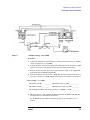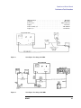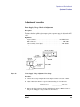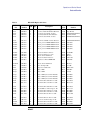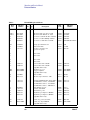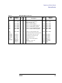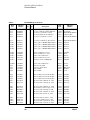
1
Notice
Hewlett-Packard to Agilent Technologies Transition
This documentation supports a product that previously shipped under the HewlettPackard company brand name. The brand name has now been changed to Agilent
Technologies. The two products are functionally identical, only our name has changed. The
document still includes references to Hewlett-Packard products, some of which have been
transitioned to Agilent Technologies.
Printed in USA
March 2000
Contacting Agilent
By internet, phone, or fax, get assistance with all your test and measurement needs.
Table 1-1 Contacting Agilent
Online assistance: www.agilent.com/find/assist
United States
(tel) 1 800 452 4844
Latin America
(tel) (305) 269 7500
(fax) (305) 269 7599
Canada
(tel) 1 877 894 4414
(fax) (905) 282-6495
New Zealand
(tel) 0 800 738 378
(fax) (+64) 4 495 8950
Japan
(tel) (+81) 426 56 7832
(fax) (+81) 426 56 7840
Australia
(tel) 1 800 629 485
(fax) (+61) 3 9210 5947
Europe
(tel) (+31) 20 547 2323
(fax) (+31) 20 547 2390
Asia Call Center Numbers
Country
Phone Number
Fax Number
Singapore
1-800-375-8100
(65) 836-0252
Malaysia
1-800-828-848
1-800-801664
Philippines
(632) 8426802
1-800-16510170 (PLDT
Subscriber Only)
(632) 8426809
1-800-16510288 (PLDT
Subscriber Only)
Thailand
(088) 226-008 (outside Bangkok)
(662) 661-3999 (within Bangkok)
(66) 1-661-3714
Hong Kong
800-930-871
(852) 2506 9233
Taiwan
0800-047-866
(886) 2 25456723
People’s Republic
of China
800-810-0189 (preferred)
10800-650-0021
10800-650-0121
India
1-600-11-2929
000-800-650-1101
2
Chapter 1
Operation and Service Manual
HP 8447D/E/F and HP 8447F H64
Amplifiers
Serial Numbers: HP 8447D, 2944A
HP 8447E, 2944A
HP 8447F, 2944A
HP 8447F H64, 3113A
HP Part No. 08447-90066
Supersedes 08447-90033, 08447-90063, 08447-90059
Printed in USA
Print Date: July 1996
Copyright Hewlett-Packard Company 1970-1996. All Rights Reserved. Reproduction, adaptation, or translation
without prior written permission is prohibited, except as allowed under the copyright laws.
1400 Fountaingrove Parkway, Santa Rosa, CA 95403-1799, USA
Legal
Legal
The information contained in this document is subject to change without notice.
Hewlett-Packard makes no warranty of any kind with regard to this material, including but not limited to, the implied warranties of merchantability and fitness for
a particular purpose. Hewlett-Packard shall not be liable for errors contained herein
or for incidental or consequential damages in connection with the furnishing, performance, or use of this material.
Safety Info
WARNING:
Warning denotes a hazard. It calls attention to a procedure which, if not correctly
performed or adhered to, could result in injury or loss of life. Do not proceed beyond a
warning note until the indicated conditions are fully understood and met.
WARNING:
This is a Safety Class I product (provided with a protective earthing ground
incorporated in the power cord). The mains plug shall only be inserted in a socket outlet
provided with a protective earth contact. Any interruption of the protective conductor,
inside or outside the instrument, is likely to make the instrument dangerous. Intentional
interruption is prohibited.
CAUTION:
Caution denotes a hazard. It calls attention to a procedure that, if not correctly performed or
adhered to, would result in damage to or destruction of the instrument. Do not proceed beyond
a caution sign until the indicated conditions are fully understood and met.
CAUTION:
This product is designed for use in Installation Category II and Pollution Degree 2.
This instrument has been designed and tested in accordance with IEC Publication
348, Safety Requirements for Electronic Measuring Apparatus, and has been supplied in a safe condition. The instruction documentation contains information and
warnings which must be followed by the user to ensure safe operation and to maintain the instrument in a safe condition.
”CSA” The CSA mark is a registered trademark of the Canadian Standards Association.
Notice for Germany: Noise Declaration LpA %< 70 dB am Arbeitsplatz (operator
position) normaler Betrieb (normal position) nach DIN 45635 T. 19 (per ISO 7779)
2
DRAFT
Operation and Service Manual
DRAFT
3
Operation and Service Manual
General Information
General Information
The HP 8447D, 8447E and 8447F are general purpose, wideband amplifiers. Each
instrument consists of a power supply and one or two thin film, hybrid, integrated
circuit amplifiers. The thin film amplifiers are hermetically sealed and feature low
noise, low distortion, flat frequency response, and long term stability and reliability.
The HP 8447D Amplifier is a pre-amplifier that provides 25 dB of gain to signals
from 100 kHz to 1.3 GHz. It can be used to increase the sensitivity of any lab,
shop or field device operating within its frequency range.
The HP 8447E Amplifier is a power amplifier that provides 22 dB of gain to signals from 100 kHz to 1.3 GHz. It can be used to increase the output power of signal generators, swept sources and similar devices operating within its frequency
range.
The HP 8447F Amplifier contains a preamplifier and a power amplifier. They are
the same thin film amplifiers used in the HP 8447D and HP 8447E. The input and
output ports of both amplifiers are available on the front panel. They can be used
separately or cascaded to provide 47 dB of gain.
The HP 8447F Option H64 Amplifier is a general purpose wide band amplifier
with Type-N connectors. It contains two preamplifiers. One provides 26 dB minimum gain to signals from 9 kHz to 50 MHz. The other provides 25 dB minimum
gain to signals from 100 kHz to 1300 MHz.
Table 1
HP 8447D and HP 8447E Specifications
HP 8447D
Preamp
Specifications
HP 8447E
Power Amp
Frequency range
0.1 to 1300 MHz
0.1 to 1300 MHz
Typical 3 dB bandwidth (Std, Opt 001 and Opt 011)
.075 to 1700 MHz
.075 to 1400 MHz
Mean Gain (20° to 30°C)
25 dB minimum
22 dB ± 2.0dB
Gain flatness across frequency range
± 1.5 dB
± 1.5 dB
Noise Figure
<8.5 dB
<11 dB (typical)
Output power for 1 dB gain compression
>+7 dBm (typical)
≥+12.5 dBm
(0.1 to 1000 MHz)
4
DRAFT
Operation and Service Manual
General Information
Table 1
HP 8447D and HP 8447E Specifications
HP 8447D
Preamp
Specifications
HP 8447E
Power Amp
Harmonic distortion
−30 dB for 0 dBm output (typical)
−30 dB for +8 dBm output
Typical output for <−60 dB harmonic distortion
−30 dBm
−20 dBm
VSWR, 1 to 1300 MHz
<2.0:1 Input
<2.2:1 Output
−−
VSWR, 1 to 1400 MHz
−−
<2.2:1 Input
<2.5:1 Output
Impedance
50 Ω
50 Ω
Reverse isolation
>40 dB
>40 dB
Maximum DC input voltage
±10 V
±10 V
Typical risetime
400 ps
420 ps
Typical group delay
1.1 nsa
1.5 nsb
Net weight
3 lbs 8 oz (1.59 kg)
3 lbs 8 oz (1.59 kg)
Option 001
3 lbs 14 oz (1.75 kg)
−−
Option 010
3 lbs 1 oz (1.84 kg)
3 lbs 10 oz (1.64 kg)
Option 011
4 lbs 10 oz (1.64 kg)
−−
Dimensions
8 1/2 in (216 mm) by 5-1/2 in (130 mm) by 3-3/8 in (85.8 mm)
Power Requirements
115 or 230 Vac ±10%, 48 to 440 Hz, 15 Watts, 27 VAmax
Environmental
Operation: 0°C to +55°C
Storage: −40°C to +75°C
a.
b.
Variation over any 50 MHz band from 0.1-1300 MHz is typically <0.15 ns.
Variation over any 50 MHz band from 0.1-1300 MHz is typically <0.25 ns.
DRAFT
5
Operation and Service Manual
General Information
Table 2
HP 8447F Specifications
Specifications
Preamp
HP 8447F
Power Amp
Preamp
HP 8447F H64
Low Freq. Preamp
Frequency range
0.1 to 1300 MHz
0.1 to 1300 MHz
0.1 to 1300 MHz
9 kHz to 50 MHz
Typical 3 dB bandwidth
(Std, Opt 001 and Opt 011)
.075 to 1700 MHz
.075 to 1400 MHz
.075 to 1700 MHz
6 kHz to 400 MHz
Mean Gain (20° to 30°C)
25 dB minimum
22 dB ± 2.0dB
25 dB minimum
26 dB minimum
Gain flatness across frequency range
± 1.5 dB
± 1.5 dB
± 1.5 dB
± 2 dB
Noise Figure
<8.5 dB
<11 dB (typical)
<8.5 dB
−−
Output power for 1 dB gain
compression
>+7 dBm (typical)
≥+12.5 dBm
(0.1 to 1000 MHz)
>+7 dBm (typical)
>+15 dBm
(0.1 to 1000 MHz)
Harmonic distortion
−30 dB for 0 dBm
−30 dB for +8 dBm
output (typical)
output
−30 dB for 0 dBm
output (typical)
−35 dBc for +10
dBm output
Typical output for <−60 dB
harmonic distortion
−30 dBm
−20 dBm
−30 dBm
−2 dBm
VSWR, 9 kHz to 50 MHz
−−
−−
−−
<2.0:1
VSWR, 1 to 1300 MHz
<2.0:1 Input
<2.2:1 Output
−−
<2.0:1 Input
<2.2:1 Output
VSWR, 1 to 1400 MHz
−−
<2.2:1 Input
<2.5:1 Output
−−
Impedance
50 Ω
50 Ω
50 Ω
50 Ω
Reverse isolation
>40 dB
>40 dB
>40 dB
−−
Maximum DC input voltage
±10 V
±10 V
±10 V
±10 V
Typical risetime
400 ps
420 ps
400 ps
−−
Typical group delay
1.1 nsa
1.5 nsb
1.1 nsa
−−
Net weight
3 lbs 14 oz (1.75 kg)
3 lbs 14 oz (1.75 kg)
Option 001
−−
−−
6
DRAFT
Operation and Service Manual
General Information
Table 2
HP 8447F Specifications
Specifications
Preamp
HP 8447F
Power Amp
HP 8447F H64
Low Freq. Preamp
Preamp
Option 010
4 lbs 1 oz (1.84 kg)
Dimensions
8 1/2 in (216 mm) by 5-1/2 in (130 mm) by 3-3/8 in (85.8 mm)
Power Requirements
115 or 230 Vac ±10%, 48 to 440 Hz, 15 Watts, 27 VAmax
Environmental
Operation: 0°C to +55°C
Storage: −40°C to +75°C
a.
b.
4 lbs 1 oz (1.84 kg)
Variation over any 50 MHz band from 0.1-1300 MHz is typically <0.15 ns.
Variation over any 50 MHz band from 0.1-1300 MHz is typically <0.25 ns.
Table 3
HP 8447F H64 Characteristics
Characteristics
Preamp
Noise figure
9 kHz to 20 kHz
20 kHz to 100 kHz
100 kHz to 50 MHz
−−
Typical mean gain (20° to 30°C)
−−
HP 8447F H64
Low Freq. Preamp
<12.0 dB
<9.0 dB
<7.0 dB
DRAFT
28 dB
7
Operation and Service Manual
General Information
Figure 1
Typical Preamplifier Performance Curves
8
DRAFT
Operation and Service Manual
General Information
Figure 2
Typical Power Amplifier Performance Curves
DRAFT
9
Operation and Service Manual
General Information
Options
The HP 8447D is a single preamplifier with BNC connectors. However, to provide flexibility, three options are offered:
a
Option 001 dual preamplifier, BNC connectors.
b Option 010 single preamplifier, Type-N connectors.
c
Option 011 dual preamplifier, Type-N connectors.
The HP 8447E is a power amplifier with BNC connectors. One option is offered:
Option 010, Type-N connectors.
The HP 8447F is a preamplifier and a power amplifier with BNC connectors. One
option is offered:
Option 010, Type-N connectors.
Option H64, Two preamplifiers with Type-N connectors. This option is not offered in
conjunction with any other options.
NOTE:
Dual amplifier option 010 is furnished with a rigid coaxial cable (W6), with
Type-N connectors, that can be used to cascade the amplifiers with minimum
loss. The option H64 dual amplifier is not supplied with this cable.
Instruments Covered by this Manual
This manual fully documents the HP 8447D, HP 8447E and the HP 8447F. Any
references in the manual apply to all three amplifiers unless otherwise noted.
Each amplifier has a ten digit serial number on the serial plate on the rear panel.
The first five digits of the serial number are a prefix. The contents of this manual
apply directly to instruments with the same serial number prefix as listed on the
inside title page.
Revisions required to adapt the manual to other serial number prefixes are contained in a yellow “Manual Changes” insert supplied with the manual. For information about serial number prefixes not listed on the title page or in the insert,
contact your nearest Hewlett-Packard office.
10
DRAFT
Operation and Service Manual
General Information
DRAFT
11
Operation and Service Manual
Receiving and Operating
Receiving and Operating
Initial Inspection
Mechanical Check
If damage to the shipping carton is evident, ask the carrier’s agent to be present
when the instrument is unpacked. Inspect the instrument for mechanical damage.
Also check the cushioning material for signs of severe stress.
Performance Check
The electrical performance of an amplifier should be verified upon receipt. Performance checks suitable for incoming inspections are given in the performance test
section.
Claims for Damage
If the instrument is mechanically damaged in transit, notify the carrier and the
nearest Hewlett-Packard field office immediately. A list of field offices is contained in the back of this manual. Retain the shipping carton and padding material
for the carrier’s inspection. The field office will arrange for replacement or repair
of your instrument without delay for claim settlements against the carrier. Before
shipment, this instrument was inspected and found free of mechanical and electrical defects. If there is any deficiency, or if electrical performance is not within
specifications, notify your nearest Hewlett-Packard sales and service office.
Preparation For Use
Power Requirements
The amplifier operates from 115 or 230 volt ac line voltages, at any line frequency
between 48 and 440 Hz. A slide switch on the rear panel is set to the correct position for the line voltage available.
Power Cable
To protect operating personnel, the National Electrical Manufacturer’s Association (NEMA) recommends that the instrument panel and cabinet be grounded. All
Hewlett-Packard instruments are equipped with a three-conductor power cable
which, when plugged into the appropriate receptacle, grounds the instrument. The
12
DRAFT
Operation and Service Manual
Receiving and Operating
offset pin on the power cable’s three-prong connector is the ground wire. The
power cord and power input connector meet the specifications established by the
International Electrotechnical Commission (IEC).
CAUTION:
Always use the three-prong ac power cord supplied with this instrument. Failure to ensure
adequate earth grounding by not using this cord may cause instrument damage.
Mating Connectors
Mating connectors used with the amplifier should be 50 Ω type BNC male. If the
amplifier has the optional Type-N connectors, use Type-N male connectors that
are compatible with US MIL-C-39012.
Operating Environment
The operating range of the amplifier is from 0°C to +55°C. The amplifier can be
stored in a temperature range of −40°C to +75°C.
Bench Use
The amplifier is equipped with plastic feet and tilt stand in place, ready for use as
a bench instrument.
WARNING:
If this product is not used as specified, the protection provided by the equipment could
be impaired. This product must be used in a normal condition only (in which all means
for protection are intact).
Rack Mounting
The amplifier may be rack mounted by using an adapter frame. The adapter frame
is a rack frame that accepts several combinations of sub-modular units. For additional information, address inquiries to your nearest Hewlett-Packard sales and
service office.
Storage and Shipment
Packaging
The following paragraphs contain a general guide to repackaging of the instrument for shipment. Refer to them for information about using the original packaging, or using other packaging.
DRAFT
13
Operation and Service Manual
Receiving and Operating
If the instrument is to be shipped to Hewlett-Packard for service or repairs, attach
a tag to the instrument identifying the owner and indicating the service or repair
required. Include the model number and full serial number of the instrument.
Original Packaging
If the original container is to be used, proceed as follows:
a
Place instrument in original container. If it is not available, a suitable container can be
purchased from your nearest Hewlett-Packard sales and service office.
b Be sure the container is well sealed with strong tape or a metal band.
Other Packing Material
If the original container is not used, proceed as follows:
a
Wrap the instrument in heavy paper or anti-static plastic before placing in inner antistatic container.
b Place packing material around all sides of the instrument and protect panel face with
cardboard strips.
c
Place instrument in a heavy carton and seal with strong tape. A double-wall carton
made of 200 pound test material is adequate.
d Mark shipping container; “Delicate Instrument. Fragile.”
Operating Instructions
Connect the line power cable to the three-prong rear panel socket and proceed as
follows:
a
Select the line power to be used (115V or 230V) with the rear panel SELECTOR
switch.
b Connect the line power cable to line power and press the LINE switch.
CAUTION:
The input to the HP 8447D/E/F and the HP 8447F Option H64 amplifiers is very
susceptible to damage from electrostatic discharge. Before connecting any coaxial cable to
the input jack of the amplifier, make certain that static electricity buildup in the cable is
completely discharged.
Do not apply power levels to the amplifier that are higher than the following:
HP 8447D: 0 dBm
HP 8447E: −10 dBm
HP 8447F preamp: 0 dBm
HP 8447F power amp: +10 dBm
14
DRAFT
Operation and Service Manual
Receiving and Operating
c
CAUTION
Attach INPUT and OUTPUT cables.
Power out of the HP 8447E and power out of the HP 8447F power amp can
exceed 100 mW. This may be enough power to damage sensitive circuits
connected to the OUTPUT.
Operator Maintenance
Operator maintenance is limited to replacement of the front panel LINE switch
light, the A1 power supply fuse, and the rear panel fuse. Clean the cabinet using a
damp cloth only.
Fuses
To replace the rear panel fuse (F1), remove the rear panel fuse knob and replace
the fuse (see rear panel for value of F1).
To replace the A1 power supply (A1F1) fuse, turn the instrument on its top. Lift
the tilt stand and remove the bottom cover. Replace the fuse on the A1 Power
Supply board (see parts list for the value of A1F1).
WARNING:
For continued protection against fire hazard replace line fuse only with same type and
rating ([0.5A/250V]). The use of other fuses or material is prohibited.
Lamp Replacement
To replace the front panel line switch lamp (DS1), proceed as follows:
a
Disconnect cord from rear panel receptacle.
b Pull the white cover portion of this switch from the instrument and then remove the
lamp from inside the cover.
c
Replace old lamp with a new lamp (see parts list for part number of DS1).
d Place white cover into switch receptacle.
e
WARNING:
Align tab on white cover with socket and push in.
No operator serviceable parts inside. Refer servicing to qualified personnel. To prevent
electrical shock, do not remove covers.
DRAFT
15
Operation and Service Manual
Performance Tests Procedures
Performance Tests Procedures
Test equipment and accessories required to perform maintenance are listed in
Table 4. Equipment other than recommended models can be used provided the
minimum specifications are satisfied.
The performance tests assume the use of a standard amplifier with BNC connectors. If an amplifier with Type-N connectors is to be tested, suitable adapters will
have to be added to the equipment lists.
The performance tests and adjustment procedure cover all three amplifiers. Where
required, test steps list equipment settings, and other additional information, for
each amplifier. If a test step lists only one setting or specification, it is valid for all
three amplifiers. Disregard references to any amplifier not being tested.
Table 4
Recommended Test Equipment and Accessories
Instrument Type
Minimum Specifications
Usea
Suggested Model
Generator/Sweeper
Frequency Range: 0.1 to 110 MHz
Flatness: ±0.25 dB over full range
Output Level: +10 dBm minimum
Frequency Accuracy: 1% ±100 kHz
Compatible with network analyzer
HP 8601A
P,T
Generator/Sweeper
Frequency Range: 9 kHz to 50MHz
Flatness: ±0.25 dB over full range
Output Level: +10 dBm minimum
Frequency Accuracy: 1% ±100 kHz
Compatible with network analyzer
HP 3335A
P,T
(for testing
opt H64)
Sweep Oscillator
Frequency Range: 0.1 to 1.3 GHz
Flatness: 0.7 dB over full range
Output Level: +10 dBm minimum
Frequency Accuracy: ±20 MHz
Compatible with network analyzer
HP 8620A/8621A
P,T
16
DRAFT
Operation and Service Manual
Performance Tests Procedures
Table 4
Recommended Test Equipment and Accessories
Instrument Type
Network analyzer
(0.1-110 MHz)
Network analyzer
(0.11 -1.4 GHz)
Phase-magnitude
display
Minimum Specifications
System with a swept source capable of measuring the amplitude of reflected signals return loss.
HP 8407A
Frequency range: 0.1 to 1300 MHz
Resolution: 0.25 dB
Accuracy: ±6%
HP 8412A
HP 8411A
S-parameter test set
HP 8745A
Universal extension
HP 11604A
Transmission kit
HP 11651A
Accessory kit
HP 11570A
Spectrum analyzer
IF section
Frequency range: 10-1300 MHz
Dynamic range: 60 dB minimum
Scan width: 800 MHz minimum
Spurious responses: <−60 dB
Absolute amplitude calibration.
Variable persistence display.
Display section
Noise figure meter
P
HP 8410A
Harmonic frequency converter
Spectrum analyzer
RF section
Usea
Suggested Model
HP 8555A
P
HP 8552A
HP 141T
Frequency range: 0.1-1300 MHz
Noise figure range: 0-15 dB
Accuracy: ±0.5 dB
Excess noise ratio: 6.3 ±0.5 dB
HP 342A
RMS voltmeter
Voltage range: 1mV to 1V (full range)
Frequency range: 10 Hz to 10 MHz
Meter accuracy: ±5%
HP 3400A
P,A,T
Power meter
Rower range: −20 dBm to +10 dBm
Frequency range: 10-1300 MHz
Meter accuracy: ±1%
HP 432A/478A
P
Amplifier
Gain: 24 dB
Noise: <8 dB
Frequency range: 0.1-130 MHz
HP 8447D
P
VHF noise source
UHF noise source
DRAFT
P
HP 343A
HP 349A
17
Operation and Service Manual
Performance Tests Procedures
Table 4
Recommended Test Equipment and Accessories
Instrument Type
Minimum Specifications
Usea
Suggested Model
Digital voltmeter
Voltage range: 0-60V
Accuracy: ±0.05% ±1 digit
HP 3440A/3444A
A, T
Double balanced
mixers
Frequency range: 200-1300 MHz
Sage Laboratories
2500 Series
P
Low pass filter
Cutoff frequency: 400 MHz
Attenuation: >60 dB at 800 and 1200 MHz
Cir-Q-Tel
FLT/2 Series
P
Attenuator
10 dB, 0.1-1300 MHz
HP 8491A
Option 010
P
Attenuator
20 dB, 0.1-1300 MHz
HP 8491A
Option 020
P
Termination
50 Ω (BNC)
HP 11593A
P
Termination
50 Ω (Type-N)
HP 908A
P
Adapter
Type-N female to BNC male
UG-349A/U
P
Adapter
BNC female to Type-N male
UG-209A/U
P
Tee
BNC
UG-274B/U
P
Cable assembly
Type-N connectors
HP 11500A
P
Cable assembly (5)
BNC connectors
HP 10503A
P
Cable assembly
BNC with test clips attached
HP 10501A
A,T
Adapter
BNC female to binding post
HP 10111A
P, A, T
Adapter
BNC male to BNC male
UG-491A/U
P
a.P=Performance Test, A=Adjustments, T=Troubleshooting
18
DRAFT
Operation and Service Manual
Performance Tests Procedures
Gain Flatness, Mean Gain, and Gain Compression Test
Specifications:
HP 8447D
Preamp
HP 8447E
Power amp
HP 8447F
Preamp
Power
Amp
HP 8447F H64
Preamp
Low Freq
Preamp
Gain flatness across
full frequency
range
±1.5 dB
±1.5 dB
±1.5 dB
±1.5 dB
±1.5 dB
±2 dB
Mean Gain
(20°C-30°C)
25 dB min.
22 dB ±2.0
dB
25 dB min.
22 dB ±2.0
dB
25 dB min.
26 dB min.
Output power for 1
dB gain compression
−−
>+12.5 dBm
−−
>+12.5 dBm
−−
>+15 dBm
Description:
Amplifier gain is measured at the maximum and minimum points of its frequency
response. See Figure 1 and Figure 2. The difference between highest measured
gain and lowest measured gain should be less than 3 dB (gain flatness). Half of the
sum of the highest gain and lowest gain is the measured mean gain and should be
within 2.0 dB of the specified gain. Compression is checked by measuring gain at
the specified 1 dB compression point and comparing it to gain measured below
compression.
Equipment:
Generator/sweeper . . . . . . . . . . . . . . . . . . . . . . . . . . . . . . . . . . . . . . . . HP 8601A
Sweep oscillator . . . . . . . . . . . . . . . . . . . . . . . . . . . . . . . . . . . . HP 8620A/8621A
RMS voltmeter . . . . . . . . . . . . . . . . . . . . . . . . . . . . . . . . . . . . . . . . . . . HP 3400A
Power meter . . . . . . . . . . . . . . . . . . . . . . . . . . . . . . . . . . . . . . . . . HP 432A/478A
BNC cable assembly (2) . . . . . . . . . . . . . . . . . . . . . . . . . . . . . . . . . . HP 10503A
BNC tee . . . . . . . . . . . . . . . . . . . . . . . . . . . . . . . . . . . . . . . . . . . . . . . UP-247B/U
50 Ω termination . . . . . . . . . . . . . . . . . . . . . . . . . . . . . . . . . . . . . . . . HP 11593A
Adapter. . . . . . . . . . . . . . . . . . . . . . . . . . . . . . . . . . . . . . . . . . . . . . . .UG-349A/U
Adapter. . . . . . . . . . . . . . . . . . . . . . . . . . . . . . . . . . . . . . . . . . . . . . . .UG-201A/U
Adapter. . . . . . . . . . . . . . . . . . . . . . . . . . . . . . . . . . . . . . . . . . . . . . HP 1250-0080
20 dB attenuator . . . . . . . . . . . . . . . . . . . . . . . . . . . . . . . . . . . . . . . .HP 8491B-20
10 dB attenuator . . . . . . . . . . . . . . . . . . . . . . . . . . . . . . . . . . . . . . . .HP 8491B-10
DRAFT
19
Operation and Service Manual
Performance Tests Procedures
Figure 3
Gain Test Setup: 10 MHz to 1.3 GHz
Procedure:
1
To measure gain flatness and mean gain, connect the equipment as shown in Figure 3.
Set the sweep oscillator for a 1.3 GHz, leveled, CW signal. Set the signal level for −10
dBm out of the 10 dB attenuator (read on the power meter).
2
Disconnect the power meter from the sweep oscillator and 10 dB attenuator. Connect
the sweep oscillator, through the 10 dB and 20 dB attenuators, to the amplifier
INPUT. Connect the power meter to the amplifier OUTPUT. Note the power meter
reading. Use this reading to calculate amplifier gain.
Example:
−7 dBm (read in step 2) minus −10 dBm (set in step 1) plus 20 dB (read from attenuator) = 23 dB (gain)
Gain at 1300 MHz:______________________dB
NOTE:
Use the attenuation printed on the 20 dB attenuator. This may vary slightly, depending
upon the frequency.
3
Tune the sweep oscillator for a maximum indication on the power meter at 1150 ±100
MHz. Disconnect the oscillator and the power meter from the amplifier. Connect the
power meter, through the 10 dB attenuator, to the oscillator. Set the oscillator signal
level for −10 dBm out of the attenuator.
4
Disconnect the power meter from the sweep oscillator and 10 dB attenuator. Connect
the oscillator, through the 10 dB and 20 dB attenuators, to the amplifier INPUT. Con-
20
DRAFT
Operation and Service Manual
Performance Tests Procedures
nect the power meter to the amplifier OUTPUT. Calculate and record the amplifier gain
as in step 2.
Gain at 1150 MHz________________________dB
5
Measure, calculate and record the amplifier gain at the following frequencies. Use the
procedures outlined in steps 3 and 4.
Frequency
Gain
800 ±200 MHz (tune for minimum):
_______________dB
350 ±100 MHz (tune for minimum):
_______________dB
6
Disconnect the sweep oscillator and the power meter from the amplifier. Connect the
equipment as shown in Figure 4. Set the generator/sweeper for a 10 MHz, CW signal.
Set the signal level for −40 dB (read on the voltmeter).
7
Disconnect the voltmeter from the generator/sweeper. Connect the generator/sweeper
to the amplifier INPUT. Connect the voltmeter, with the 50 Ω termination, to the amplifier OUTPUT. Note the voltmeter reading. Use this reading to calculate the amplifier
gain.
Example:
−18.5 dB (read in step 7) minus −40 dB (set in step 6) = 21.5 dB (gain)
Gain at 1300 MHz:______________________dB
Figure 4
Flatness and Mean Gain Test Setup: 100 kHz to 10 MHz
8
Measure, calculate and record amplifier gain at the following frequencies. Use the procedures outlined above.
DRAFT
21
Operation and Service Manual
Performance Tests Procedures
Frequency
Gain
250 ±100 kHz (tune for maximum):
_______________dB
100 kHz:
_______________dB
For HP 8447F H64 low frequency preamp, replace the generator/sweeper shown in
Figure 4 with HP 3335A synthesizer (or equivalent). Set the synthesizer for a 9 kHz,
CW signal. Repeat step 7. Measure, calculate and record the amplifier gain at 9 kHz.
HP 8447F H64 Frequency
9 kHz:
9
Gain
_______________dB
Select the highest and lowest gains from steps 2, 4, 5, 7, and 8. Subtract the lowest gain
from the highest gain. The result is gain flatness and should be less than 3 dB.
Example:
23 dB (highest gain) minus 21.5 dB (lowest gain) = 1.5 dB (gain flatness)
Gain flatness:__________________dB
For HP 8447F H64 low frequency preamp, select the highest and lowest gains from
steps 7, and 8. Subtract the lowest gain from the highest gain. The result is gain flatness and should be less than 4 dB (±2 dB). Add the highest and lowest gains together
and divide by 2. The result is measured gain.
Measured gain:__________________dB
10 Add the highest and lowest gains together and divide by 2. The result is the measured
mean gain.
Example:
23 dB (highest gain) + 21.5 dB (lowest gain)
------------------------------------------------------------------------------------------------------------ = 22.25 dB (mean gain)
2
22
DRAFT
Operation and Service Manual
Performance Tests Procedures
NOTE:
Mean Gain
Min
Actual
HP 8447D
25 dB
________
HP 8447E
20 dB
________
HP 8447F preamp
25 dB
________
HP 8447F power amp
20 dB
________
Max
24 dB
24 dB
Gain rolls off rapidly above 1300 MHz and below 0.1 MHz. If the lowest gain was
measured at either of these points, use a frequency counter to monitor the signal and repeat
steps 1 through 10.
11 To check compression, connect the power meter mount, through the 10 dB attenuator,
to the amplifier OUTPUT as shown in Figure 3. Connect the sweep oscillator, through
the 20 dB attenuator, to the amplifier INPUT. Set the sweep oscillator for a leveled, 650
MHz, CW signal and set the signal level (read on the power meter) as follows:
(For the HP 8447F H64 low frequency preamp set the 3335A to 10 MHz)
HP 8447E:
+2.5 dBm (+11.5 dBm ampl. output)
HP 8447F power amp:
+2.5 dBm (+11.5 dBm ampl. output)
12 Without changing any of the sweep oscillator settings, move the 10 dB attenuator from
the amplifier OUTPUT to the amplifier INPUT. The power meter should now be connected directly to the amplifier OUTPUT and the sweep oscillator should be connected
through the 20 dB attenuator and the 10 dB attenuator to the amplifier
INPUT.
13 The power meter should read as follows:
HP 8447E
less than +3.5 dBm:
_____________dBm
HP 8447F power amp
less than +3.5 dBm:
_____________dBm
HP 8447F H64 low frequency preamp
less than +6 dBm:
_____________dBm
14 Repeat steps 11 through 13 at various frequencies between 0.1 and 1300 MHz.
For the HP 8447F H64 low frequency preamp repeat steps 11 through 13 at various
frequencies between 0.1 to 50 MHz.
DRAFT
23
Operation and Service Manual
Performance Tests Procedures
VSWR Test Procedure
Specifications,
HP 8447D
Preamp
(1 to 1300
MHz)
HP 8447E
Power Amp
(0.75 to 1400
MHz)
VSWR:
HP 8447F
Preamp
Power Amp
(1 to 1300 MHz) (0.75 to 1400
MHz)
HP 8447F H64
Preamp
Low Freq Preamp
(1 to 1300 MHz)
(1 to 50 MHz)
<2.0 Input
<2.2 Input
<2.0 Input
<2.2 Input
<2.0 Input
<2.0 Input
<2.2 Output
<2.5 Output
<2.2 Output
<2.5 Output
<2.2 Output
<2.2 Output
Description:
A network analyzer is swept, in steps, from 1 to 1300 MHz (or 1400 MHz). At
each step the analyzer display is referenced to 1 dB return loss by shorting its output. The short is then removed and the amplifier return loss is measured at the
INPUT and OUTPUT.
Equipment:
Sweep oscillator. . . . . . . . . . . . . . . . . . . . . . . . . . . . . . . . . . . . HP 8620A/8621A
Generator/sweeper . . . . . . . . . . . . . . . . . . . . . . . . . . . . . . . . . . . . . . . . HP 8601A
Network analyzer (0.1 to 110 MHz) . . . . . . . . . . . . . . . . . . . . . . . . . . HP 8407A
Network analyzer (0.11 to 1.4 GHz) . . . . . . . . . . . . . . . . . . . . . . . . . . HP 8410A
Phase-magnitude displayHP 8412A
Harmonic frequency converter . . . . . . . . . . . . . . . . . . . . . . . . . . . . . . HP 8411A
S-parameter test set . . . . . . . . . . . . . . . . . . . . . . . . . . . . . . . . . . . . . . . HP 8745A
Universal extension . . . . . . . . . . . . . . . . . . . . . . . . . . . . . . . . . . . . . . HP 11604A
Transmission kit. . . . . . . . . . . . . . . . . . . . . . . . . . . . . . . . . . . . . . . . . HP 11651A
Accessory kit . . . . . . . . . . . . . . . . . . . . . . . . . . . . . . . . . . . . . . . . . . . HP 11570A
Cable assembly (3) . . . . . . . . . . . . . . . . . . . . . . . . . . . . . . . . . . . . . . HP 10503A
Cable assembly . . . . . . . . . . . . . . . . . . . . . . . . . . . . . . . . . . . . . . . . . HP 11500A
24
DRAFT
Operation and Service Manual
Performance Tests Procedures
Figure 5
VSWR Test Setup: 1 to 110 MHz
Procedure:
1
Connect the equipment as shown in Figure 5. Set the generator/sweeper for a −10 dBm
signal, sweeping from 1 to 110 MHz.
2
Connect the short to the directional bridge and calibrate the network analyzer for a 0 dB
return loss reference on the display (use the center horizontal graticule line).
3
Remove the short from the directional coupler, attach the coupler to the amplifier INPUT. (Terminate the OUTPUT with 50 Ω.)
4
Decrease the display reference level to −10 dB. The center horizontal graticule line now
represents a return loss of 10 dB. The measured return loss should be as shown below:
INPUT VSWR, 1 to 110 MHz
HP 8447D, >9.6 dB:___________
HP 8447F Preamp, >9.6 dB:_____________
HP 8447E, >8.8 dB:___________
HP 8447F Power amp, >8.8 dB:__________
HP 8447F Option H64 Low frequency preamp, 1 to 50 MHz >9.6 dB:__________
5
Measure return loss at the amplifier OUTPUT. Terminate the INPUT with 50Ω. The
measured return loss should be as shown below.
For the HP 8447F option H64 low frequency preamp, steps 7 through 11 are not
needed.
DRAFT
25
Operation and Service Manual
Performance Tests Procedures
Figure 6
HP 8447D Output VSWR, 1 to 110 MHz:
>8.8 dB
_____________
HP 8447E/F Output VSWR, 1 to 110 MHz:
>7.7 dB
_____________
HP 8447F Option H64 low frequency preamp
Output VSWR, 1 to 50 MHz:
>9.6 dB
_____________
VSWR Test Setup: 0.11 to 1.3 GHz
6
26
Connect the equipment as shown in Figure 6. Set the sweep oscillator for a leveled CW
signal, sweeping from 110 to 220 MHz. Connect the power meter to the s-parameter
test set INPUT PORT A and set the generator/sweeper output level for −15 dBm as read
on the power meter.
DRAFT
Operation and Service Manual
Performance Tests Procedures
7
Disconnect the power meter from the test set and connect a short to INPUT PORT A
(measuring S11 at INPUT PORT A). Calibrate the network analyzer for a 0 dB return
loss reference on the display. Use the center horizontal graticule line. Note the TEST
CHANNEL GAIN at the reference:
Reference TEST CHAN. GAIN, 110 to 220 MHz:
___________dB
8
Disconnect the short from INPUT PORT A. Terminate the amplifier OUTPUT with 50
Ω. Connect INPUT PORT A to the amplifier INPUT.
9
Set the TEST CHANNEL GAIN 10 dB above the reference in step 7. The center horizontal graticule line now represents a return loss of 10 dB. The measured return loss
should be as shown below:
INPUT VSWR, 110 to 220 MHz
HP 8447D, >9.6 dB:__________
HP 8447F Preamp, >9.6 dB:_____________
HP 8447E, >8.8 dB:__________
HP 8447F Power amp, >8.8 dB:__________
10 Repeat steps 8 and 9, measuring return loss at the amplifier OUTPUT. Terminate the
amplifier INPUT with 50Ω. The measured return loss should be as shown below:
HP 8447D Output VSWR, 110 to 220 MHz:
8.8 dB
_____________
HP 8447E/F Output VSWR, 110 to 220 MHz:
7.7 dB
_____________
11 Set the sweep oscillator to sweep each of the ranges shown below, repeating steps 7
through 10 for each range.
Sweep Range
Reference,
Test Chan.
Gain
HP 8447D Input,
HP 8447F Preamp
Input
HP 8447D Output,
HP 8447E Input,
HP 8447F Power
Amp Input
HP 8447E/F
Output
220 to 440 MHz
_________dB
__________dB
___________dB
__________dB
440 to 880 MHz
_________dB
__________dB
___________dB
__________dB
880 to 1300 MHz
_________dB
__________dB
___________dB
__________dB
DRAFT
27
Operation and Service Manual
Performance Tests Procedures
Distortion and Reverse Isolation Test Procedure
Specifications:
Specification
Harmonic
Distortion
HP 8447D
Preamp
HP 8447E
Power Amp
−−
−30 dB for
+8 dBm out-
HP 8447F
Preamp
Power Amp
−−
put
Reverse
Isolation
>40 dB
>40 dB
−30 dB for
+8 dBm out-
HP 8447F H64
Preamp
Low Freq
Preamp
−−
put
>40 dB
>40 dB
−35 dB for
+10 dBm output
>40 dB
−−
Description:
A fixed, CW signal at 400 MHz is filtered and applied to the amplifier INPUT.
The amplifier OUTPUT is connected to a spectrum analyzer, and the analyzer is
used to check the second and third harmonic levels. Reverse isolation is checked
by applying a known signal level to the amplifier OUTPUT and measuring it at
the amplifier INPUT.
Equipment:
Spectrum analyzer . . . . . . . . . . . . . . . . . . . . . . . . . . . . . .HP 141T/8552A/8555A
Sweep oscillator. . . . . . . . . . . . . . . . . . . . . . . . . . . . . . . . . . . . HP 8620A/8621A
400 MHz low pass filter . . . . . . . . . . . . . . . . . . . . . . . . . Cir-Q-Tel FLT/2 Series
Cable assembly . . . . . . . . . . . . . . . . . . . . . . . . . . . . . . . . . . . . . . . . . HP 10503A
Adapter . . . . . . . . . . . . . . . . . . . . . . . . . . . . . . . . . . . . . . . . . . . . . . . UG-201A/U
10 dB attenuator. . . . . . . . . . . . . . . . . . . . . . . . . . . . . . . . . . . . . . . . HP 8491B-10
Adapter . . . . . . . . . . . . . . . . . . . . . . . . . . . . . . . . . . . . . . . . . . . . . . . UG-349A/U
Cable assembly . . . . . . . . . . . . . . . . . . . . . . . . . . . . . . . . . . . . . . . . . HP 11500A
28
DRAFT
Operation and Service Manual
Performance Tests Procedures
Figure 7
Distortion and Reverse Isolation Test Setup
Procedure:
1
To check distortion, connect the equipment as shown in Figure 7. Set the sweep oscillator for a fixed, 400 MHz CW signal.
For the HP 8447F option H64 low frequency preamp, set the frequency to 10 MHz.
2
Set the spectrum analyzer input attenuator as shown below. Adjust the controls to display 400 through 1200 MHz.
For the HP 8447F option H64 low frequency preamp, set the controls to display 10
through 30 MHz.
NOTE:
The signal into the spectrum analyzer input mixer must be low enough to eliminate
harmonic distortion in the spectrum analyzer.
3
Set the sweep oscillator output level for the following signal levels out of the amplifier
(read on the spectrum analyzer).
Signal Level
4
Spectrum Analyzer
Input Attenuation
HP 8447E:
+8 dBm
50 dB
HP 8447F Power Amp:
+8 dBm
50 dB
HP 8447F H64 Low freq preamp:
+10 dBm
50 dB
Note the level of the second harmonic at 800 MHz and the third harmonic at 1200 MHz.
DRAFT
29
Operation and Service Manual
Performance Tests Procedures
The harmonic signal levels should be >30 dB below the fundamental.
For the HP 8447F option H64 low frequency preamp, note the level of the second harmonic at 20 MHz and the third harmonic at 30 MHz. The harmonic signal levels
should be >35 dB below the fundamental.
HP 8447F H64
Harmonic Distortion, 30 dB down:
_____________
Harmonic Distortion, 35 dB down:
_____________
5
To check reverse isolation, disconnect the oscillator and the spectrum analyzer from the
amplifier, reduce the oscillator’s output level, then connect the oscillator to the spectrum analyzer.
6
Set the oscillator output level for a 0 dBm signal as read on the spectrum analyzer. Connect the spectrum analyzer to the amplifier INPUT. Connect the oscillator to the amplifier OUTPUT.
7
Read the level of feed-through directly on the spectrum analyzer. It should be below −
40 dBm:
Reverse isolation, >40 dB down:
________________
Noise Figure Test Procedure
Specifications:
Noise Figure: <8.5 dB (for the HP 8447D and HP 8447F preamp)
Characteristics
Noise Figure: <7.0 dB (for the HP 8447F option H64 low frequency preamp)
Description:
Noise figure is checked at 100 MHz by inserting a known amount of excess noise
into the amplifier under test. The known noise is then compared to the amplifier’s
noise level with a noise figure meter. Noise is checked at 200 MHz using a
1300MHz signal source and a mixer to convert the noise to 100 MHz. Then it is
measured with the meter.
Equipment:
Noise figure meter . . . . . . . . . . . . . . . . . . . . . . . . . . . . . . . . . . . . . . . . . HP 342A
VHF noise source . . . . . . . . . . . . . . . . . . . . . . . . . . . . . . . . . . . . . . . . . HP 343A
UHF noise source . . . . . . . . . . . . . . . . . . . . . . . . . . . . . . . . . . . . . . . . . HP 349A
Sweep oscillator. . . . . . . . . . . . . . . . . . . . . . . . . . . . . . . . . . . . HP 8620A/8621A
Double balanced mixers . . . . . . . . . . . . . . . . . . . . . . . . . . . . . . . . SL 2513/2523
30
DRAFT
Operation and Service Manual
Performance Tests Procedures
50Ω termination . . . . . . . . . . . . . . . . . . . . . . . . . . . . . . . . . . . . . . . . . . . HP 908A
Amplifier . . . . . . . . . . . . . . . . . . . . . . . . . . . . . . . . . . . . . . . . . . . . . . . HP 8447D
Power meter . . . . . . . . . . . . . . . . . . . . . . . . . . . . . . . . . . . . . . . . . HP 432A/478A
Adapter. . . . . . . . . . . . . . . . . . . . . . . . . . . . . . . . . . . . . . . . . . . . . . . . . UG-491/U
Cable assembly (5). . . . . . . . . . . . . . . . . . . . . . . . . . . . . . . . . . . . . . . HP 10503A
Adapter (2) . . . . . . . . . . . . . . . . . . . . . . . . . . . . . . . . . . . . . . . . . . . . .UG-201A/U
Figure 8
Noise Figure Test Setup: 100 MHz
Figure 9
Noise Figure Test Setup: 1200 MHz
DRAFT
31
Operation and Service Manual
Performance Tests Procedures
Procedure:
1
Connect the equipment as shown in Figure 8. Calibrate the noise figure meter. Check
the amplifier’s noise figure at 100 MHz (or 105 MHz). It should be less than 8.5 dB.
For the HP 8447F option H64 low frequency preamp, check the amplifier’s noise figure at 30 MHz. It should be less than 7 dB.
HP 8447F H64 low frequency preamp
NOTE:
100 MHz:
________________
30 MHz:
________________
2
Connect the equipment as shown in Figure 9. Set the sweep oscillator for a fixed, CW
signal at 1300 MHz. Set the signal level out of the oscillator for +10 dBm, read on the
power meter.
3
Disconnect the power meter from the oscillator and connect the oscillator to the
mixer.
4
Set the noise figure meter to measure noise at 100 MHz. Calibrate the meter.
If the noise figure meter being used has a 105 MHz input frequency, set the sweep oscillator
(in step 2) to 1305 MHz.
5
Check the amplifier’s noise figure. It should be less than 8.5 dB.
1200 MHz:
32
________________
DRAFT
Operation and Service Manual
Adjustment Procedure
Adjustment Procedure
Power Supply Voltage Check and Adjustment
Description:
To insure that the amplifier gives proper gain, the power supply is adjusted to 20V
±0.1V.
Equipment:
Digital voltmeter . . . . . . . . . . . . . . . . . . . . . . . . . . . . . . . . . . . HP 3440A/3444A
RMS voltmeter . . . . . . . . . . . . . . . . . . . . . . . . . . . . . . . . . . . . . . . . . . . HP 3400A
Cable assembly (w/test clips). . . . . . . . . . . . . . . . . . . . . . . . . . . . . . . HP 10501A
Adapter. . . . . . . . . . . . . . . . . . . . . . . . . . . . . . . . . . . . . . . . . . . . . . . . HP 10111A
Figure 10
Power Supply Voltage Adjustment Test Setup
Procedure:
1
Connect the test setup in Figure 10. Set the digital voltmeter to measure +20V dc.
2
Adjust A1R9 VOLT ADJ for a digital voltmeter reading of +20V ±0.1V dc.
DVM: +19.9V dc
3
_________________+20.1V dc
Remove the digital voltmeter from the amplifier and connect the RMS voltmeter to
XA1 pin 14. The ripple voltage should be as shown below.
DRAFT
33
Operation and Service Manual
Parts and Service
Parts and Service
Replaceable Parts
The following tables list parts in alpha-numerical order of their reference designations. It is important that you refer to the table that documents the instrument
being serviced. Cabinet parts for all three amplifiers are listed in Figure 11. HP
8447D/E/F Cabinet Parts. Figure 12. HP 8447D/E/F Type-N Connector (Options
010 and 011) lists the parts that make up the Type-N connector used in amplifier
Options 010 and 100.
Ordering Information
To obtain replacement parts, address order or inquiry to your local Hewlett-Packard field office. See the list at the end of the manual for addresses. Identify parts
by their Hewlett-Packard part numbers.
To obtain a part that is not listed, include:
a
Instrument model number
b Instrument serial number
c
Description of the part
d Function and location of the part
Table 5
Reference Designators
A
B
BT
C
CP
CR
DL
DS
E
F
FL
J
= assembly
= motor
= battery
= capacitor
= coupler
= diode
= delay line
= lamp, device signal
= misc. electronic part
= fuse
= filter
= jack
34
K
L
LS
M
MK
MP
P
Q
R
RT
S
T
= relay
= inductor
= loud speaker
= meter
= microphone
= mechanical part
= plug
= transistor
= resistor
= thermistor
= switch
= transformer
TB
TP
U
V
VR
W
X
Y
Z
= terminal board
= test point
= integrated circuit
= vacuum tube,
neon bulb,
photocell, etc.
= voltage regulator
= cable
= socket
= crystal
= tuned cavity,
network
DRAFT
Operation and Service Manual
Parts and Service
Table 6
A
AFC
AMPL
Abbreviations
= amperes
= automatic frequency
control
= amplifier
BFO
BECU
BH
BP
BRS
BWO
= beat freq oscillator
= beryllium copper
= binder head
= bandpass
= brass
= backward wave
oscillator
G
GE
GL
GRD
= giga (109)
= germanium
= glass
= ground(ed)
H
HDW
DEX
HG
HR
Hz
= henries
= hardware
= hexagonal
= mercury
= hour(s)
= Hertz
IF
= intermediate freq
N
N/C
NE
NIPL
N/O
NOM
NPO
= nano (10-9)
= normally closed
= neon
= nickel plate
= normally open
= nominal
= negative positive zero
(zero temp coefficient)
= negative-positive-neg
= not recommended for
field replacement
= not separately
replaceable
NPN
NRFR
NSR
DRAFT
CCW
CER
CMO
COEF
COM
COMP
COMPL
CONN
CP
CRT
CW
= counterclockwise
= ceramic
= cabinet mount only
= coefficient
= common
= composition
= complete
= connector
= cadmium plate
= cathode-ray-tube
= clockwise
DEPC
DR
= deposited carbon
= drive
ELECT
ENCAP
EXT
= electrolytic
= encapsulated
= external
F
FH
FILH
FXD
= farads
= flat head
= Fillister head
= fixed
IMPG
INCD
INCL
INS
INT
= impregnated
= incandescent
= include(s)
= insulation(ed)
= internal
K
= kilo (1000)
LH
LIN
LKWASH
LOG
LPF
= left hand
= linear taper
= lock washer
= logarithmic taper
= low pass filter
M
MEG
METFLM
METOX
MFR
MHz
MINAT
MOM
MOS
MTG
MY
= milli (10-3)
= meg (106)
= metal film
= metallic oxide
= manufacturer
= mega Hertz
= miniature
= momentary
= metalized substrate
= mounting
= mylar
OBD
OH
OX
= order by description
= oval head
= oxide
P
PC
PF
PHBRZ
PHL
PIV
PNP
P/O
POLY
= peak
= printed circuit
= picofarads (10-12 F)
= phosphor bronze
= Phillips
= peak inverse voltage
= positive-negative-pos
= part of
= polystrene
PORC
POS
POTZ
PP
PT
PWV
= porcelain
= position(s)
= potentiometer
= peak-to-peak
= point
= peak working voltage
RECT
RF
RH
= rectifier
= radio frequency
= round head, right
hand
= rack mount only
= root-mean square
= reverse working volt
RMO
RMS
RWV
35
Operation and Service Manual
Parts and Service
Table 6
S-B
SCR
SE
SECT
SEMICN
SI
SIL
SL
SPG
SPL
SST
SR
STL
Abbreviations
= slow-blow
= screw
= selenium
= section(s)
= semiconductor
= silicon
= silver
= slide
= spring
= special
= stainless steel
= split ring
= steel
Table 7
TA
TD
TGL
THD
TI
TOL
TRIM
TWT
= tantalum
= time delay
= toggle
= thread
= titanium
= tolerance
= trimmer
= traveling wave tube
µ
= micro (10-6)
VAR
VDCW
= variable
= dc working volts
W/
W
WIV
WW
W/O
= with
= watts
= working inverse
voltage
= wirewound
= without
Code List of Manufacturers
Mfr No
Manufacturer Name
Address
Zip Code
01121
Allen Bradley Co.
Milwaukee, WI
53204
01921
RCA Solid State Div.
Somerville, NJ
08876
02037
Motorola Semiconductor Products
Phoenix, AZ
85008
04009
Arrow, Hart & Hegeman Electric Co.
Hartford, CT
06106
04703
Littelfuse Inc.
Des Plaines, IL
60016
04757
Oak Ind. Inc., Sw Div.
Crystal Lake, IL
60014
07263
Fairchild Camera & Instr. Corp., Semiconductor Div.
Mountain View, CA
94040
12954
Dickson Electronic Corp.
Scottsdale, AZ
85282
28480
Hewlett-Packard Co.
Palo Alto, CA
94304
56289
Sprague Electric Co.
N. Adams, MA
01247
70903
Belden Corp.
Chicago, IL
60644
71590
Globe Union Inc. Central Lab Div.
Milwaukee, WI
53201
71785
Cinch Mfg. Co., Div TRW Inc.
Elk Grove Village, IL
78189
Shakeproof Div. Illinois Tool Works
Elgin, IL
60120
80131
Electronic Industries Association
Washington, DC
20006
82389
Switchcraft Inc.
Chicago, IL
60630
87034
Marcoak Industries
Anaheim, CA
92803
91506
Augat, Inc.
Attleboro, MA
02703
Parts Lists
36
DRAFT
Operation and Service Manual
Parts and Service
Table 8
Ref
Des
HP 8447D Replaceable Parts
HP Part
Number
CD
qty
Description
Mfr
Code
Mfr Part
Number
A1
A1C1
A1C2
A1C3
A1C4
08447-60045
0150-0024
0180-0228
0160-0162
0180-0116
0
7
6
5
1
1
1
1
1
1
Board Assy: Power Supply
C: fixd cer 0.02 uF +80-20% 600 Vdcw
C: fixd elect 22 uF 10% 15 Vdcw
C: fixd my 0.022 uF 10% 200 Vdcw
C: fixd elect 6.8uF 10% 35 Vdcw
28480
71590
56289
56289
56289
08447-60045
Type DD 203
150D226X9015B2DYS
192P22392-PTS
150D685X9035B2DYS
A1C5
A1CR1
A1CR2
A1CR3
A1CR4
0180-1819
1901-0743
1901-0743
1901-0743
1901-0743
3
1
1
1
1
1
4
C: fixd elect 100 uF +75-10% 50 Vdcw
Diode: pwr rect IN4004 400VIA DO-41
Diode: pwr rect IN4004 400VIA DO-41
Diode: pwr rect IN4004 400VIA DO-41
Diode: pwr rect IN4004 400VIA DO-41
56289
28480
28480
28480
28480
150D226X9015B2DYS
1901-0743
1901-0743
1901-0743
1901-0743
A1CR5
A1CR6
A1CR7
A1CR8
A1CR9
1920-3002
1902-0761
1901-0025
1902-3268
1884-0073
1
5
2
3
2
1
1
2
1
1
Diode: breakdown 3.16V 5%
Diode: breakdown 5.9 - 6.5V
Diode: silicon 100 mA/1V
Diode: breakdown 26.1V 5%
Thyristor-scr TO-5 VRRM=100
28480
12954
07263
28480
01921
1920-3002
1N821
FD 2387
1902-3268
SCR1400
A1CR10
A1F1
A1F1
A1Q1
A1Q2
1901-0025
2110-0012
2110-0269
1853-0012
1854-0022
2
0
9
4
8
2
1
1
1
Diode: silicon 100 mA/1V
Fuse: 0.5 amp 250V
Clip: fuse: 0.250” diam.
Xstr: si PNP
Xstr: si NPN
07263
04703
91506
80131
07263
FD 2387
312.500
6008-32CN
2N2904A
S17843
A1Q3
A1Q4
A1Q5
A1R1
A1R2
1854-0071
1854-0071
1854-0071
0757-0836
0698-7238
7
7
7
6
9
3
1
1
Xstr: si NPN (selected from 2N3704)
Xstr: si NPN (selected from 2N3704)
Xstr: si NPN (selected from 2N3704)
R: fixd met flm 7.50 kohm 1% 1/2W
R: fixd met flm 1.78 kohm 1% 1/8W
28480
28480
28480
28480
28480
1854-0071
1854-0071
1854-0071
0757-0836
0698-7238
A1R3
A1R4
A1R5
A1R6
A1R7
0757-0836
0811-1732
0698-0089
0698-0083
0698-3440
5
8
4
8
7
1
1
1
1
1
R: fixd met flm 7.50 kohm 1% 1/2W
R: fixd WW 1.5 ohm 5% Type V 1W
R: fixd met flm 1780 ohm 1% 1/8W
R: fixd met flm 1.96 kohm 1% 1/8W
R: fixd met flm 196 ohm 1% 1/8W
28480
28480
28480
28480
28480
0757-0836
0811-1732
0698-0089
0698-0083
0698-3440
A1R8
A1R9
A1R10
A1R11
0757-0416
2100-1758
0698-3154
0757-1094
7
3
0
9
1
1
1
1
R: fixd met flm 511 ohm 1% 1/8W
R: var ww 1 kohm 5% Type V 1W
R: fixd met flm 4.22 kohm 1% 1/8W
R: fixd met flm 1.47 kohm 1% 1/8W
28480
28480
28480
28480
0757-0416
2100-1758
0698-0083
0757-1094
DRAFT
37
Operation and Service Manual
Parts and Service
Table 8
Ref
Des
HP 8447D Replaceable Parts
HP Part
Number
CD
qty
Description
Mfr
Code
Mfr Part
Number
A1R12
0698-3442
9
1
R: fixd met flm 237 ohm 1% 1/8W
28480
0698-3442
A1R13
A1R14
C1
C2
C3
0757-0180
0757-0401
0180-2805
0160-2049
0180-0291
2
0
9
1
3
1
R: fixd met flm 31.6 ohm 1% 1/8W
R: fixd met flm 100 ohm 1% 1/8W
C: fixd elect 850 uF +50-10% 75VDCW
C: fixd cer feedthru 5000 pF +80-20%
C: fixd elect 1.0 uF 10% 35 VDCW
28480
28480
28480
28480
56289
0757-0180
0757-0401
0180-2805
0160-2049
150D105X9035A2DYS
DS1
F1
J1
2140-0244
2110-0012
1251-2357
4
1
8
1
Lamp: glow miniature 95V
Fuse: 0.5A 250V
Socket: 3-pin male power
(part of rear panel)
87034
04703
82389
A1H
312.500
EAC-301
28480
28480
9100-1618
9100-1618
28480
28480
08447-00005
08447-00028
80131
01121
2N3055
CB 2735
28480
28480
3101-2139
3101-2195
04009
82389
28480
28480
28480
899U-3
11A-1242
9100-2894
5086-7767
5086-7767
70903
28480
KHS-7041
08447-20002
1
1
1
1
J2
J3
Part of W2
Part of W3
J4
J5
L1
L2
9100-1618
9100-1618
1
1
2
MP1
MP2
08447-00005
08447-00028
6
3
1
1
Q1
R1
1854-0063
0683-2735
7
0
1
1
Part of W4
Part of W5
Coil: molded choke 5.60 uH
Coil: molded choke 5.60 uH
(Opt 001 and 011 only)
Insulator: top cover
Support: amplifier
(Opt 001 and 011 only)
Xstr: si NPN
R: fixd comp 27 kohm 5% 1/4W
S1
S1
3101-2139
3101-2195
9
1
1
S1
S2
T1
U1
U2
0590-0012
3101-1234
9100-2894
5086-7767
5086-7767
5
3
7
7
7
2
1
1
1
1
W1
W2
8120-1348
08447-20002
5
5
1
1
38
Switch-pb DPST-NO altng 10.5A 250Vac
for HP 8447D, serial no. 2727A06246
for HP 8447E, serial no. 2727A02669
for HP 8447F, serial no. 2805A03498
Nut: knurled 15/32-32
Switch: slide DPDT
Transformer: power
Hybrid mc:pre-ampl 0.1-1300 MHz
Hybrid mc:pre-ampl 0.1-1300 MHz
(Opt 001 and 011 only)
Cable assy: power, detachable
Cable assy: Type-N INPUT
(Opt 010 and 011 only)
DRAFT
Operation and Service Manual
Parts and Service
Table 8
Ref
Des
HP 8447D Replaceable Parts
HP Part
Number
CD
qty
W2
W3
08447-20006
08447-20003
9
6
1
1
W3
W4
W4
W5
W5
08447-20007
08447-20004
08447-20008
08447-20005
08447-20009
0
7
1
8
2
1
1
1
1
1
W6
XF1
XF1MP1
XF1MP2
XF1MP3
XQ1
XF1MP4
08447-20014
9
1
2110-0564
2110-0565
2110-0569
0340-1114
1400-0090
0360-0368
0900-0016
8
9
3
1
1
1
1
1
1
1
9
7
8
DRAFT
Description
Mfr
Code
Mfr Part
Number
Cable assy: BNC INPUT
Cable assy: Type-N OUTPUT
(Opt 010 and 011 only)
Cable assy: BNC OUTPUT
Cable assy: Type-N INPUT (Opt 011)
Cable assy: BNC INPUT (Opt 001)
Cable assy: Type-N OUTPUT (Opt 011)
Cable assy: BNC OUTPUT (Opt 001)
28480
28480
08447-20006
08447-20003
28480
28480
28480
28480
28480
08447-20007
08447-20004
08447-20008
08447-20005
08447-20009
Cable assy: jumper (Opt 011 only)
Fuseholder (includes the following parts)
Fuseholder body 12A max for UL
Fuseholder cap 12A max for UL
Nut-fuseholder thread
Insulator: xstr mounting (TO-3)
Washer
Termination: solder stud
O-ring 0.688” OD
28480
08447-20014
28480
28480
28480
28480
28480
78189
00000
2110-0564
2110-0565
2110-0569
0340-1114
1400-0090
2168-12-01
OBD
39
Operation and Service Manual
Parts and Service
Table 9
Ref
Des
HP 8447E Replaceable Parts
HP Part
Number
CD
qty
Description
Mfr
Code
Mfr Part
Number
A1
A1C1
A1C2
A1C3
A1C4
08447-60045
0150-0024
0180-0228
0160-0162
0180-0116
0
7
6
5
1
1
1
1
1
1
Board Assy: Power Supply
C: fixd cer 0.02 uF +80-20% 600 Vdcw
C: fixd elect 22 uF 10% 15 Vdcw
C: fixd my 0.022 uF 10% 200 Vdcw
C: fixd elect 6.8uF 10% 35 Vdcw
28480
71590
56289
56289
56289
08447-60045
Type DD 203
150D226X9015B2DYS
192P22392-PTS
150D685X9035B2DYS
A1C5
A1CR1
A1CR2
A1CR3
A1CR4
0180-1819
1901-0743
1901-0743
1901-0743
1901-0743
3
1
1
1
1
1
4
C: fixd elect 100 uF +75-10% 50 Vdcw
Diode: pwr rect IN4004 400VIA DO-41
Diode: pwr rect IN4004 400VIA DO-41
Diode: pwr rect IN4004 400VIA DO-41
Diode: pwr rect IN4004 400VIA DO-41
56289
28480
28480
28480
28480
150D226X9015B2DYS
1901-0743
1901-0743
1901-0743
1901-0743
A1CR5
A1CR6
A1CR7
A1CR8
A1CR9
1920-3002
1902-0761
1901-0025
1902-3268
1884-0073
1
5
2
3
2
1
1
2
1
1
Diode: breakdown 3.16V 5%
Diode: breakdown 5.9 - 6.5V
Diode: silicon 100 mA/1V
Diode: breakdown 26.1V 5%
Thyristor-scr TO-5 VRRM=100
28480
12954
07263
28480
01921
1920-3002
1N821
FD 2387
1902-3268
SCR1400
A1CR10
A1F1
A1F1
A1Q1
A1Q2
1901-0025
2110-0012
2110-0726
1853-0012
1854-0022
2
0
9
4
8
2
1
1
1
Diode: silicon 100 mA/1V
Fuse: 0.5 amp 250V
Clip: fuse: 0.250” diam.
Xstr: si PNP
Xstr: si NPN
07263
04703
91506
80131
07263
FD 2387
312.500
6008-32CN
2N2904A
S17843
A1Q3
A1Q4
A1Q5
A1R1
A1R2
1854-0071
1854-0071
1854-0071
0757-0836
0698-7238
7
7
7
6
9
3
1
1
Xstr: si NPN (selected from 2N3704)
Xstr: si NPN (selected from 2N3704)
Xstr: si NPN (selected from 2N3704)
R: fixd met flm 7.50 kohm 1% 1/2W
R: fixd met flm 1.78 kohm 1% 1/8W
28480
28480
28480
28480
28480
1854-0071
1854-0071
1854-0071
0757-0836
0698-7238
A1R3
A1R4
A1R5
A1R6
A1R7
0757-0836
0811-1832
0698-0089
0698-0083
0698-3440
5
8
4
8
7
1
1
1
1
1
R: fixd met flm 7.50 kohm 1% 1/2W
R: fixd WW 1.5 ohm 5% Type V 1W
R: fixd met flm 1780 ohm 1% 1/8W
R: fixd met flm 1.96 kohm 1% 1/8W
R: fixd met flm 196 ohm 1% 1/8W
28480
28480
28480
28480
28480
0757-0836
0811-1832
0698-0089
0698-0083
0698-3440
A1R8
A1R9
A1R10
A1R11
0757-0416
2100-1758
0698-3154
0757-1094
7
3
0
9
1
1
1
1
R: fixd met flm 511 ohm 1% 1/8W
R: var ww 1 kohm 5% Type V 1W
R: fixd met flm 4.22 kohm 1% 1/8W
R: fixd met flm 1.47 kohm 1% 1/8W
28480
28480
28480
28480
0757-0416
2100-1758
0698-0083
0757-1094
40
DRAFT
Operation and Service Manual
Parts and Service
Table 9
Ref
Des
HP 8447E Replaceable Parts
HP Part
Number
CD
qty
Description
Mfr
Code
Mfr Part
Number
A1R12
0698-3442
9
1
R: fixd met flm 237 ohm 1% 1/8W
28480
0698-3442
A1R13
A1R14
C1
C2
C3
0757-0180
0757-0401
0180-2805
0160-2049
0180-0291
2
0
9
1
3
1
R: fixd met flm 31.6 ohm 1% 1/8W
R: fixd met flm 100 ohm 1% 1/8W
C: fixd elect 850 uF +50-10% 75VDCW
C: fixd cer feedthru 5000 pF +80-20%
C: fixd elect 1.0 uF 10% 35 VDCW
28480
28480
28480
28480
56289
0757-0180
0757-0401
0180-2805
0160-2049
150D105X9035A2DYS
DS1
F1
J1
2140-0244
2110-0012
1251-2357
4
1
8
1
Lamp: glow miniature 95V
Fuse: 0.5A 250V
Socket: 3-pin male power
(part of rear panel)
87034
04703
82389
A1H
312.500
EAC-301
Coil: molded choke 5.60 uH
Coil: molded choke 5.60 uH
(Opt 001 and 011 only)
Insulator: top cover
Xstr: si NPN
R: fixd comp 27 kohm 5% 1/4W
28480
28480
9100-1618
9100-1618
28480
80131
01121
08447-00005
2N3055
CB 2735
Switch-pb DPST-NO altng 10.5A 250Vac
for HP 8447D, serial no. 2727A06246
for HP 8447E, serial no. 2727A02669
for HP 8447F, serial no. 2805A03498
Nut: knurled 15/32-32
Switch: slide DPDT
Transformer: power
Hybrid mc:power-ampl 0.1-1300 MHz
5086-7768 replacement kit (for use with
08447-60045 assy).
28480
28480
3101-2139
3101-2195
04009
82389
28480
28480
28480
899U-3
11A-1242
9100-2894
5086-7767
08447-60029
70903
28480
KHS-7041
08447-20002
28480
28480
08447-20006
08447-20003
28480
08447-20007
1
1
1
1
J2
J3
Part of W2
Part of W3
L1
L2
9100-1618
9100-1618
1
1
2
MP1
Q1
R1
08447-00005
1854-0063
0683-2735
6
7
0
1
1
1
S1
S1
3101-2139
3101-2195
9
1
1
S1
S2
T1
U1
U1
0590-0012
3101-1234
9100-2894
5086-7768
08447-60029
5
3
7
7
2
1
1
1
W1
W2
8120-1348
08447-20002
5
5
1
1
W2
W3
08447-20006
08447-20003
9
6
1
1
W3
08447-20007
0
1
DRAFT
Cable assy: power, detachable
Cable assy: Type-N INPUT
(Opt 010 and 011 only)
Cable assy: BNC INPUT
Cable assy: Type-N OUTPUT
(Opt 010 and 011 only)
Cable assy: BNC OUTPUT
41
Operation and Service Manual
Parts and Service
Table 9
Ref
Des
XF1
XF1MP1
XF1MP2
XF1MP3
XQ1
XF1MP4
HP 8447E Replaceable Parts
HP Part
Number
2110-0564
2110-0565
2110-0569
0340-0664
1400-0090
0360-0368
0900-0016
CD
qty
8
9
3
1
1
1
1
1
1
1
9
7
8
42
Description
Fuseholder (includes the following parts)
Fuseholder body 12A max for UL
Fuseholder cap 12A max for UL
Nut-fuseholder thread
Insulator: xstr mounting (TO-3)
Washer: lock sst for 1/2 thread
Termination: solder stud
O-ring 0.688” OD
Mfr
Code
28480
28480
28480
28480
28480
78189
00000
Mfr Part
Number
2110-0564
2110-0565
2110-0569
0340-0664
1400-0090
2168-12-01
OBD
DRAFT
Operation and Service Manual
Parts and Service
Table 10
Ref
Des
HP 8447F Replaceable Parts
HP Part
Number
CD
qty
Description
Mfr
Code
Mfr Part
Number
A1
A1C1
A1C2
A1C3
A1C4
08447-60045
0150-0024
0180-0228
0160-0162
0180-0116
0
7
6
5
1
1
1
1
1
1
Board Assy: Power Supply
C: fixd cer 0.02 uF +80-20% 600 Vdcw
C: fixd elect 22 uF 10% 15 Vdcw
C: fixd my 0.022 uF 10% 200 Vdcw
C: fixd elect 6.8uF 10% 35 Vdcw
28480
71590
56289
56289
56289
08447-60045
Type DD 203
150D226X9015B2DYS
192P22392-PTS
150D685X9035B2DYS
A1C5
A1CR1
A1CR2
A1CR3
A1CR4
0180-1819
1901-0743
1901-0743
1901-0743
1901-0743
3
1
1
1
1
1
4
C: fixd elect 100 uF +75-10% 50 Vdcw
Diode: pwr rect IN4004 400VIA DO-41
Diode: pwr rect IN4004 400VIA DO-41
Diode: pwr rect IN4004 400VIA DO-41
Diode: pwr rect IN4004 400VIA DO-41
56289
28480
28480
28480
28480
150D226X9015B2DYS
1901-0743
1901-0743
1901-0743
1901-0743
A1CR5
A1CR6
A1CR7
A1CR8
A1CR9
1920-3002
1902-0761
1901-0025
1902-3268
1884-0073
1
5
2
3
2
1
1
2
1
1
Diode: breakdown 3.16V 5%
Diode: breakdown 5.9 - 6.5V
Diode: silicon 100 mA/1V
Diode: breakdown 26.1V 5%
Thyristor-scr TO-5 VRRM=100
28480
12954
07263
28480
01921
1920-3002
1N821
FD 2387
1902-3268
SCR1400
A1CR10
A1F1
A1F1
A1Q1
A1Q2
1901-0025
2110-0012
2110-0269
1853-0012
1854-0022
2
0
9
4
8
2
1
1
1
Diode: silicon 100 mA/1V
Fuse: 0.5 amp 250V
Clip: fuse: 0.250” diam.
Xstr: si PNP
Xstr: si NPN
07263
04703
91506
80131
07263
FD 2387
312.500
6008-32CN
2N2904A
S17843
A1Q3
A1Q4
A1Q5
A1R1
A1R2
1854-0071
1854-0071
1854-0071
0757-0836
0698-7238
7
7
7
6
9
3
1
1
Xstr: si NPN (selected from 2N3704)
Xstr: si NPN (selected from 2N3704)
Xstr: si NPN (selected from 2N3704)
R: fixd met flm 7.50 kohm 1% 1/2W
R: fixd met flm 1.78 kohm 1% 1/8W
28480
28480
28480
28480
28480
1854-0071
1854-0071
1854-0071
0757-0836
0698-7238
A1R3
A1R4
A1R5
A1R6
A1R7
0757-0836
0811-1732
0698-0089
0698-0083
0698-3440
5
8
4
8
7
1
1
1
1
1
R: fixd met flm 7.50 kohm 1% 1/2W
R: fixd WW 1.5 ohm 5% Type V 1W
R: fixd met flm 1780 ohm 1% 1/8W
R: fixd met flm 1.96 kohm 1% 1/8W
R: fixd met flm 196 ohm 1% 1/8W
28480
28480
28480
28480
28480
0757-0836
0811-1732
0698-0089
0698-0083
0698-3440
A1R8
A1R9
A1R10
A1R11
0757-0416
2100-1758
0698-3154
0757-1094
7
3
0
9
1
1
1
1
R: fixd met flm 511 ohm 1% 1/8W
R: var ww 1 kohm 5% Type V 1W
R: fixd met flm 4.22 kohm 1% 1/8W
R: fixd met flm 1.47 kohm 1% 1/8W
28480
28480
28480
28480
0757-0416
2100-1758
0698-0083
0757-1094
DRAFT
43
Operation and Service Manual
Parts and Service
Table 10
Ref
Des
HP 8447F Replaceable Parts
HP Part
Number
CD
qty
Description
Mfr
Code
Mfr Part
Number
A1R12
0698-3442
9
1
R: fixd met flm 237 ohm 1% 1/8W
28480
0698-3442
A1R13
A1R14
C1
C2
C3
0757-0180
0757-0401
0180-2805
0160-2049
0180-0291
2
0
9
1
3
1
R: fixd met flm 31.6 ohm 1% 1/8W
R: fixd met flm 100 ohm 1% 1/8W
C: fixd elect 850 uF +50-10% 75VDCW
C: fixd cer feedthru 5000 pF +80-20%
C: fixd elect 1.0 uF 10% 35 VDCW
28480
28480
28480
28480
56289
0757-0180
0757-0401
0180-2805
0160-2049
150D105X9035A2DYS
DS1
F1
J1
2140-0244
2110-0012
1251-2357
4
1
8
1
Lamp: glow miniature 95V
Fuse: 0.5A 250V
Socket: 3-pin male power
(part of rear panel)
87034
04703
82389
A1H
312.500
EAC-301
28480
28480
9100-1618
9100-1618
28480
28480
08447-00005
08447-00028
80131
01121
2N3055
CB 2735
Switch-pb DPST-NO altng 10.5A 250Vac
for HP 8447D, serial no. 2727A06246
for HP 8447E, serial no. 2727A02669
for HP 8447F, serial no. 2805A03498
Nut: knurled 15/32-32
Switch: slide DPDT
Transformer: power
28480
28480
3101-2139
3101-2195
04009
82389
28480
899U-3
11A-1242
9100-2894
Hybrid mc:power-ampl 0.1-1300 MHz
5086-7768 replacement kit (for use with
08447-60045 assy).
Hybrid mc:pre-ampl 0.1-1300 MHz
(Opt 001 and 011 only)
28480
28480
5086-7768
08447-60029
28480
5086-7767
1
1
1
1
J2
J3
Part of W2
Part of W3
J4
J5
L1
L2
9100-1618
9100-1618
1
1
2
MP1
MP2
08447-00005
08447-00028
6
3
1
1
Q1
R1
1854-0063
0683-2735
7
0
1
1
Part of W4
Part of W5
Coil: molded choke 5.60 uH
Coil: molded choke 5.60 uH
(Opt 001 and 011 only)
Insulator: top cover
Support: amplifier
(Opt 001 and 011 only)
Xstr: si NPN
R: fixd comp 27 kohm 5% 1/4W
S1
S1
3101-2139
3101-2195
9
1
1
S1
S2
T1
0590-0012
3101-1234
9100-2894
5
3
7
2
1
1
U1
U1
5086-7768
08447-60029
7
1
U2
5086-7767
7
1
44
DRAFT
Operation and Service Manual
Parts and Service
Table 10
Ref
Des
HP 8447F Replaceable Parts
HP Part
Number
CD
qty
U2
08447-60044
W1
W2
8120-1348
08447-20002
5
5
1
1
W2
W3
08447-20006
08447-20003
9
6
1
1
W3
W4
W4
W5
W5
08447-20007
08447-20004
08447-20008
08447-20005
08447-20009
0
7
1
8
2
1
1
1
1
1
W6
XF1
XF1MP1
XF1MP2
XF1MP3
XQ1
XF1MP4
08447-20014
9
1
2110-0564
2110-0565
2110-0569
0340-0664
1400-0090
0360-0368
0900-0016
8
9
3
1
1
1
1
1
1
1
9
7
8
DRAFT
Description
Mfr
Code
Mfr Part
Number
5086-7767 replacement kit (for use with
08447-60045 assy).
28480
08447-60044
Cable assy: power, detachable
Cable assy: Type-N INPUT
(Opt 010 and 011 only)
Cable assy: BNC INPUT
Cable assy: Type-N OUTPUT
(Opt 010 and 011 only)
Cable assy: BNC OUTPUT
Cable assy: Type-N INPUT (Opt 010)
Cable assy: BNC INPUT
Cable assy: Type-N OUTPUT (Opt 010)
Cable assy: BNC OUTPUT
70903
28480
KHS-7041
08447-20002
28480
28480
08447-20006
08447-20003
28480
28480
28480
28480
28480
08447-20007
08447-20004
08447-20008
08447-20005
08447-20009
28480
08447-20014
28480
28480
28480
28480
28480
78189
00000
2110-0564
2110-0565
2110-0569
0340-0664
1400-0090
2168-12-01
OBD
Cable assy: jumper (Opt 011 only)
Fuseholder (includes the following parts)
Fuseholder body 12A max for UL
Fuseholder cap 12A max for UL
Nut-fuseholder thread
Insulator: xstr mounting (TO-3)
Washer: lock sst for 1/2 thread
Termination: solder stud
O-ring 0.688” OD
45
Operation and Service Manual
Parts and Service
Table 11
Ref
Des
HP 8447F H64 Replaceable Parts
HP Part
Number
CD
qty
Description
Mfr
Code
Mfr Part
Number
A1
A1C1
A1C2
A1C3
A1C4
08447-60045
0150-0024
0180-0228
0160-0162
0180-0116
0
7
6
5
1
1
1
1
1
1
Board Assy: Power Supply
C: fixd cer 0.02 uF +80-20% 600 Vdcw
C: fixd elect 22 uF 10% 15 Vdcw
C: fixd my 0.022 uF 10% 200 Vdcw
C: fixd elect 6.8uF 10% 35 Vdcw
28480
71590
56289
56289
56289
08447-60045
Type DD 203
150D226X9015B2DYS
192P22392-PTS
150D685X9035B2DYS
A1C5
A1CR1
A1CR2
A1CR3
A1CR4
0180-1819
1901-0743
1901-0743
1901-0743
1901-0743
3
1
1
1
1
1
4
C: fixd elect 100 uF +75-10% 50 Vdcw
Diode: pwr rect IN4004 400VIA DO-41
Diode: pwr rect IN4004 400VIA DO-41
Diode: pwr rect IN4004 400VIA DO-41
Diode: pwr rect IN4004 400VIA DO-41
56289
28480
28480
28480
28480
150D226X9015B2DYS
1901-0743
1901-0743
1901-0743
1901-0743
A1CR5
A1CR6
A1CR7
A1CR8
A1CR9
1920-3002
1902-0761
1901-0025
1902-3268
1884-0073
1
5
2
3
2
1
1
2
1
1
Diode: breakdown 3.16V 5%
Diode: breakdown 5.9 - 6.5V
Diode: silicon 100 mA/1V
Diode: breakdown 26.1V 5%
Thyristor-scr TO-5 VRRM=100
28480
12954
07263
28480
01921
1920-3002
1N821
FD 2387
1902-3268
SCR1400
A1CR10
A1F1
A1F1
A1Q1
A1Q2
1901-0025
2110-0012
2110-0269
1853-0012
1854-0022
2
0
9
4
8
2
1
1
1
Diode: silicon 100 mA/1V
Fuse: 0.5 amp 250V
Clip: fuse: 0.250” diam.
Xstr: si PNP
Xstr: si NPN
07263
04703
91506
80131
07263
FD 2387
312.500
6008-32CN
2N2904A
S17843
A1Q3
A1Q4
A1Q5
A1R1
A1R2
1854-0071
1854-0071
1854-0071
0757-0836
0698-7238
7
7
7
6
9
3
1
1
Xstr: si NPN (selected from 2N3704)
Xstr: si NPN (selected from 2N3704)
Xstr: si NPN (selected from 2N3704)
R: fixd met flm 7.50 kohm 1% 1/2W
R: fixd met flm 1.78 kohm 1% 1/8W
28480
28480
28480
28480
28480
1854-0071
1854-0071
1854-0071
0757-0836
0698-7238
A1R3
A1R4
A1R5
A1R6
A1R7
0757-0836
0811-1732
0698-0089
0698-0083
0698-3440
5
8
4
8
7
1
1
1
1
1
R: fixd met flm 7.50 kohm 1% 1/2W
R: fixd WW 1.5 ohm 5% Type V 1W
R: fixd met flm 1780 ohm 1% 1/8W
R: fixd met flm 1.96 kohm 1% 1/8W
R: fixd met flm 196 ohm 1% 1/8W
28480
28480
28480
28480
28480
0757-0836
0811-1732
0698-0089
0698-0083
0698-3440
A1R8
A1R9
A1R10
A1R11
0757-0416
2100-1758
0698-3154
0757-1094
7
3
0
9
1
1
1
1
R: fixd met flm 511 ohm 1% 1/8W
R: var ww 1 kohm 5% Type V 1W
R: fixd met flm 4.22 kohm 1% 1/8W
R: fixd met flm 1.47 kohm 1% 1/8W
28480
28480
28480
28480
0757-0416
2100-1758
0698-0083
0757-1094
46
DRAFT
Operation and Service Manual
Parts and Service
Table 11
Ref
Des
HP 8447F H64 Replaceable Parts
HP Part
Number
CD
qty
Description
Mfr
Code
Mfr Part
Number
A1R12
0698-3442
9
1
R: fixd met flm 237 ohm 1% 1/8W
28480
0698-3442
A1R13
A1R14
0757-0180
0757-0401
2
0
1
R: fixd met flm 31.6 ohm 1% 1/8W
R: fixd met flm 100 ohm 1% 1/8W
28480
28480
0757-0180
0757-0401
A2
A2C1
A2C2
A2C3
A2C4
A2J3
A2J4
08447-60038
0160-4441
0160-4441
0160-4441
0160-4441
1250-1220
1250-1220
1
4
Board Assy: H64 Amplifier
C: fixd cer 0.47 uF 50 Vdcw
C: fixd cer 0.47 uF 50 Vdcw
C: fixd cer 0.47 uF 50 Vdcw
C: fixd cer 0.47 uF 50 Vdcw
Conn: RF M SMC (output)
Conn: RF M SMC (input)
28480
08447-60038
A2L1
A2L2
A2MP1
A2MP2
A2MP3
A2MP4
9140-0351
9100-2486
1205-1220
1205-1220
3050-0082
3050-0082
1
1
2
A2Q1
A2Q2
A2R1
A2R2
1813-0213
1813-0213
0698-3631
0698-3629
2
C1
C2
C3
C4
0180-2805
0160-2049
0180-0291
0160-2049
DS1
F1
J1
2
2
Coil: 18 nH 5%
Coil: 330 nH 5%
Heatsink: T05/T39
Heatsink: T05/T39
Washer: fiber 0.116 ID 4
Washer: fiber 0.116 ID 4
1
1
IC: MWA130M1 amp
IC: MWA130M1 amp)
R: fixd 330 ohm 5% 2W
R: fixd 270 ohm 5% 2W
9
1
3
1
1
1
1
C: fixd elect 850 uF +50-10% 75VDCW
C: fixd cer feedthru 5000 pF +80-20%
C: fixd elect 1.0 uF 10% 35 VDCW
C: fixd cer 5000 pF +80-20% 200VDCW
28480
28480
56289
28480
0180-2805
0160-2049
150D105X9035A2DYS
0180-2805
2140-0244
2110-0012
4
1
1
Lamp: glow miniature 95V
Fuse: 0.5A 250V
87034
04703
A1H
312.500
1251-2357
8
1
Socket: 3-pin male power
(part of rear panel)
Part of W2
Part of W3
Part of W4
Part of W5
82389
EAC-301
J2
J3
J4
J5
DRAFT
47
Operation and Service Manual
Parts and Service
Table 11
Ref
Des
HP 8447F H64 Replaceable Parts
HP Part
Number
CD
qty
L1
L2
9100-1618
9100-1618
1
1
2
MP1
MP5
MP6
Q1
R1
08447-00005
08447-00082
08447-00069
1854-0063
0683-2735
6
S1
S1
S2
T1
Description
Mfr
Code
Mfr Part
Number
28480
28480
9100-1618
9100-1618
7
0
1
1
1
1
1
Coil: molded choke 5.60 uH
Coil: molded choke 5.60 uH
(Opt 001 and 011 only)
Insulator: top cover
Bracket: pc board support
CATV cable assy cover
Xstr: si NPN
R: fixd comp 27 kohm 5% 1/4W
28480
28480
28480
80131
01121
08447-00005
08447-00082
08447-00069
2N3055
CB 2735
3101-2195
0590-0012
3101-1234
9100-2894
5
3
7
1
2
1
1
Switch-pb DPST
Nut: knurled 15/32-32
Switch: slide DPDT
Transformer: power
28480
04009
82389
28480
3101-2195
899U-3
11A-1242
9100-2894
U1
5086-7767
7
1
28480
5086-7767
U1
08447-60044
Hybrid mc:pre-ampl 0.1-1300 MHz
(Opt 001 and 011 only)
5086-7767 replacement kit (for use with
08447-60045 assy).
28480
08447-60044
W1
W2
W3
W4
8120-1348
08447-20043
08447-20044
08447-20051
70903
28480
28480
28480
KHS-7041
08447-20043
08447-20044
08447-20051
W5
08447-20046
1
28480
08447-20046
XA1
1251-0135
1
Part of main deck: 15-pin connector)
2848
0
1251-0135
28480
28480
28480
28480
2110-0564
2110-0565
2110-0569
1400-0090
28480
78189
00000
0340-0664
2168-12-01
OBD
XF1
XF1MP1
XF1MP2
XF1MP3
XF1MP4
XQ1
5
1
1
1
1
Cable assy: power, detachable
Cable assy: Type-N INPUT
Cable assy: Type-N OUTPUT
Cable assy: Type-N INPUT flexible coaxial
Cable assy: Type-N OUTPUT flexible
coaxial
2110-0564
2110-0565
2110-0569
1400-0090
8
9
3
9
1
1
1
1
Fuseholder (includes the following parts)
Fuseholder body 12A max for UL
Fuseholder cap 12A max for UL
Nut-fuseholder thread
Washer: lock sst for 1/2 thread
0340-0664
0360-0368
0900-0016
7
8
1
1
1
Insulator: xstr mounting (TO-3)
Termination: solder stud
O-ring 0.688” OD
48
DRAFT
Operation and Service Manual
Parts and Service
Figure 11
Index
Number
HP 8447D/E/F Cabinet Parts
Part Number
CD
1
08447-0029
4
Deck, main
2
5000-7891
8
Side cover, blue gray
2
5000-8766
8
Side cover, olive gray
2
3
5060-0247
0
Frame assembly
2
4
1490-0031
7
Stand, tilt
1
5
5060-0708
8
Top cover, blue gray
5
5060-8553
7
Top cover, olive gray
1
6
08447-00050
0
Panel, rear
1
7
5060-0727
1
Foot assembly
2
8
5000-0710
6
Bottom Cover, blue gray
DRAFT
Description
Qty
1
49
Operation and Service Manual
Parts and Service
Index
Number
Part Number
CD
8
5040-8569
9
Bottom Cover, olive gray
1
9
5040-0700
8
Hinge
1
10
08447-00070
5
Panel, front (8447D standard)
1
08447-00071
6
Panel, front (8447D Opt 001)
1
08447-00072
7
Panel, front (8447D Opt 010)
1
08447-00073
8
Panel, front (8447D Opt 011)
1
08447-00062
5
Panel, front (8447E standard)
1
08447-00063
6
Panel, front (8447E Opt 010)
1
08447-00074
9
Panel, front (8447F standard)
1
08447-00075
0
Panel, front (8447F Opt 010)
1
Panel, front (8447F Opt H64)
1
08447-00081
Description
Qty
08447-00040
9
Panel, front (8447D standard) mint gray
1
08447-00041
0
Panel, front (8447D Opt 001) mint gray
1
08447-00042
1
Panel, front (8447D Opt 010) mint gray
1
08447-00043
2
Panel, front (8447D Opt 011) mint gray
1
08447-00044
3
Panel, front (8447E standard) mint gray
1
08447-00045
4
Panel, front (8447E Opt 010) mint gray
1
08447-00046
5
Panel, front (8447F standard) mint gray
1
08447-00047
6
Panel, front (8447F Opt 010) mint gray
1
50
DRAFT
Operation and Service Manual
Parts and Service
Figure 12
Index
No.
HP 8447D/E/F Type-N Connector (Options 010 and 011)
Part No.
CD
Description
Index
No.
Part No.
CD
Description
1
1250-0914
7
Body, RF conn
5
5040-0306
0
Insulator
2
1250-0915
8
Contact, RF conn
6
08555-20094
5
Contact, jack
3
2190-0444
1
Washer, lock
7
08555-20094
6
Body bulkhead
4
2950-0132
6
Nut, hex
8
08761-2027
4
Insulator
08559-60002
Complete assembly
DRAFT
51
Operation and Service Manual
Parts and Service
Figure 13
Internal Views
52
DRAFT
Operation and Service Manual
Parts and Service
Test Equipment and Accessories Required For Troubleshooting
Test equipment and accessories required to troubleshoot the amplifier are shown
in Table 4. Test instruments other than those listed may be used provided their
specifications meet or exceed those listed in the table.
General Service Information
The part reference designator is the assembly designator plus the part designator.
(Example: A1R9 is R9 on the A1 Power Supply Assembly.) Refer to the parts list
of the desired model number for the specific component description for ordering
parts.
Additional technical assistance may be obtained by contacting your local HewlettPackard sales and service office. Some of these offices are listed in Table 13.
WARNING:
These servicing instructions are for use by qualified personnel only. To avoid electrical
shock, do not perform any servicing unless you are qualified to do so.
WARNING:
The opening of covers or removal of parts is likely to expose dangerous voltages.
Disconnect the instrument from all voltage sources while it is being opened.
WARNING:
The power cord is connected to internal capacitors that may remain live for 10 seconds
after disconnecting the plug from its power supply.
Troubleshooting Procedure
First check the input and output cables. Isolate the trouble to the amplifier(s) or
power supply by checking the +20 volts at XA1-14 after removing the red wire
from C2. If the voltage is present, replace the amplifier (re-attach the red wire to
C2). If voltage is not present or incorrect, check the power supply. The voltages
shown are typical with the amplifier(s) disconnected from the power supply.
Equipment:
Digital voltmeter . . . . . . . . . . . . . . . . . . . . . . . . . . . . . . . . . . . HP 3440A/3444A
Cable assembly (w/test clips). . . . . . . . . . . . . . . . . . . . . . . . . . . . . . . HP 10501A
Adapter. . . . . . . . . . . . . . . . . . . . . . . . . . . . . . . . . . . . . . . . . . . . . . . . HP 10111A
DRAFT
53
Operation and Service Manual
Parts and Service
Figure 14
A1 Power Supply Component Locations, 08447-60011
Figure 15
A1 Power Supply Component Locations, 08447-60045
54
DRAFT
Operation and Service Manual
Parts and Service
Figure 16
A2 Amplifier Board Component Locations, 08447-60038
Figure 17
A2 Amplifier Board Schematic (replaces U2 on Figure 18)
DRAFT
55
Operation and Service Manual
Parts and Service
Figure 18
Amplifier and Power Supply Circuits
56
DRAFT
Operation and Service Manual
Manual Backdating Changes
Manual Backdating Changes
This manual does not contain backdating information.
When backdating information is required you would adapt this manual to your
instrument by making all of the manual changes listed opposite your instrument
serial number in the following table. Perform these changes in the alphabetical
sequence listed.
For additional important information about serial number coverage, refer to
Instruments Covered By Manual.
Table 12
Manual Changes By Serial Number Prefix
Serial Prefix
DRAFT
Make Manual Changes
57