1
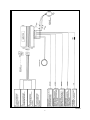
Model IMO-720
Installation Manual
IMO-720 Two Circuit Immobilizer System
Kit Contents:
Control Module
5 Pin Main Control Module Wiring Harness
4 Pin High Current Inhibit Circuit Wiring Harness
Valet/Override Switch/LED Combination Assembly
2 Pin Exciter Coil
Consumer Transponder/Information Kit
Operation:
The IMO-720 Immobilizer is a passive arming security system. When the ignition switch is turned off, the LED
begins to flash rapidly, indicating that the circuit will arm in 15 seconds.
After the 15 second arming period, the LED will begin it’s slow flash pattern, indicating that the circuit is armed.
NOTE: The arming cycle can be suspended anytime during the initial 15 seconds by turning the ignition switch
to the on position.
Once the circuit has armed, the vehicle will not start unless a programmed transponder is used or, the manual
override sequence is operated.
When the vehicle door is opened, or when the ignition switch is turned to the on position, the exciter coil is
energized and capable of reading a programmed transponder.
When a transponder is placed within the exciter coil’s field, (Appx. 6”), the unit disarms. This is indicated by the
LED turning off.
Because the programmed transponder is attached the vehicle’s key ring, the operation of this unit is transparent
to the user. Arming and Disarming takes place automatically.
Control Module Mounting:
Select an inconspicuous mounting location below the driver’s side dashboard that is within 30 inches of the
ignition key cylinder. Be certain your chosen location is away from the vehicle’s steering shaft, (column), to
prevent interference with the proper operation and control of the vehicle. Secure the module to a existing brace or,
wiring harness using cable ties.
Mounting The Valet/Override Switch/LED Assembly:
Select a mounting location within the drivers area that is accessible to the operator of the vehicle and
clearly visible from the outside of the vehicle’s front left and right windows. This switch does not have to be
hidden as the system cannot be disarmed unless the pre-programmed transponder is used or the custom
override code sequence is operated.
Mounting The Exciter Coil:
The loop exciter/antenna coil is designed to be placed around the vehicle’s ignition key cylinder. In certain
vehicles it will be necessary to remove the shroud surrounding the steering column, in other vehicles it may be
necessary to remove the cylinder from the dash panel. The information below references both these applications.
Vehicles with steering column ignition cylinders:
Remove the upper and lower half of the steering column shroud to gain access to the ignition key cylinder. Place
the loop coil around the ignition cylinder. Route the twisted pair of Black and Black w/White stripe wires toward
the control module.
Replace the upper and lower halves of the steering column shroud using care not to pinch the wire’s of the routed
exciter coil harness.
1
Vehicles with dash mounted ignition switches:
Remove the lower dash panel to gain access to the ignition key cylinder. Carefully remove the ignition key
cylinder from it’s dashboard mounting. Place the loop coil over the ignition cylinder and reinstall the ignition key
cylinder into it’s dashboard mounting location. Route the twisted pair of wires, Black and Black w/White stripe
toward the control module. In some cases it may be difficult to remove the cylinder from it’s mounting location,
in other cases, by placing the coil and reinstalling the cylinder, the coil will be crushed. For these applications,
it is possible to place the loop coil along side the ignition cylinder from behind the dash panel. It is extremely
important that you mount the loop coil as near to the key cylinder as possible to assure operation. Please review
the loop coil field and transponder relationship diagrams shown right side of the diagram below.
Wiring The Control Module:
5 Pin Main Wiring Harness:
1 Red Wire: + 12 Volt Supply:
This is the constant on battery source for the control circuit. This wire is to be connected to a constant + 12 volt
source using the 5 amp fuse provided. This wire will be connected last after wiring all other components. Do not
connect this wire until instructed later under the heading “Final Connections”.
2 Black Wire: Chassis Ground:
This is the ground source for the control circuit. Connect this wire to a known ground source or to a clean non painted
metal section of the vehicle chassis. NOTE: Be certain to remove any paint to insure a proper ground is made.
3 Yellow Wire: Ignition Input:
This is the ignition input wire for the control circuit. This wire also controls operation of the on board relays.
When the circuit is armed and this wire has +12 volts, the on board relays do not energize thereby, interrupt the
flow of current to the inhibit circuit (s) they are connected to. This wire must be connected to a source that has
+ 12 volts when the ignition switch is turned to the run and start positions and must have 0 volts when the ignition
switch is in the off position. This wire also wakes up the exciter coil to allow the transponder to receive and
transmit information to the control circuit’s arming and disarming functions.
NOTE: This immobilizer utilizes a normally open relay configuration. Be certain that the #1 + 12 Volt, #2 Chassis
Ground, #3 Ignition Control wires are securely connected to their proper location to insure vehicle operation.
4 Brown Wire: Negative Door Input:
This is the negative door input control wire, which wakes up the exciter coil, in negative pin switched door
applications. Typically General Motor, and some Imports vehicles use negative switched door pin switch circuits.
Connect this wire to the wire that switches to ground when the drivers door is opened.
5 Purple Wire: Positive Door Input:
This is the positive door input control wire, which wakes up the exciter coil, in positive pin switched door applications.
Typically Ford, Lincoln, and Mercury, and some Imports vehicles use positive switched door pin switch circuits.
Connect this wire to the wire that switches to positive 12 volts when the drivers door is opened.
NOTE: Wire #4, negative door input, or wire #5, positive door input, along with wire #3, ignition input, are used to
wake up the exciter coil enabling the transponder to receive and transmit information to the control
circuit. In addition, these wires are used during the transponder programming sequence. It is imperative
that one of these wires #4 or #5 be used in all applications dependent on the door pin’s switching polarity.
2
4 Pin Inhibit Control Harness:
6 Inhibit Circuit Relay #1 Open Contact
7 Inhibit Circuit Relay #1 Common Contact
8 Inhibit Circuit Relay #2 Common Contact
9 Inhibit Circuit Relay #2 Open Contact
The onboard, 30 Amp, inhibit circuit relays are capable of interrupting any circuit that will prevent the vehicle from
running. These circuits include, Starter, Ignition, or Electric Fuel Pump.
To interrupt these devices:
1 Locate the low current feed wires for any two of these circuits.
2 At a convenient location cut the feed wire of one of the chosen inhibit circuits, ( Low current starter, Ignition
supply, or Electric Fuel Pump supply), and route the pair of wires 6&7 from the control module to the cut wires.
3 Connect wire # 6 to the key side of the cut wire.
4 Connect wire # 7 to the device side of the cut wire.
5 At a convenient location cut the feed wire of the remaining chosen inhibit circuit, and route the pair of wires
8 & 9 from the control module to the cut wires.
6 Connect wire # 8 to the device side of the cut wire.
7 Connect wire # 9 to the key side of the cut wire.
NOTE: It is imperative that the above connections are secure as they will prevent proper operation if they become
loose or disconnected. If using butt connectors, pull on the connections to insure their integrity. If
splicing these connections, it is best to solder and then tape the joints to be certain that they are secure.
Final Connections:
Route the two pin plugs from the Exciter Coil, LED, and Override/Valet Switch to the control module and plug
each into the mating connector on the control module. Now, connect wire #1 to a constant + 12 Volt source.
Programming Dealer Or Customer Transponders:
First Time Power Up:
When the IMO-720 is first powered up it will be in the armed mode. The unit was shipped from the factory with
a DLM-1 being the last transponder programmed.
NOTE:Before beginning the program sequence, have available the proper (DLM), “Dealer Group Master Transponder” to
insure proper coding for the particular dealership.
If the unit is being programmed for the consumer transponders have all the consumer transponders available as
these will be used during step 7 below.
Once you’ve entered the program mode, all transponder codes that were previously stored will be erased. Only
the Dealer Group Transponders, (DLM & DLU), or the consumer transponders programmed during the programming sequence will operate the unit.
The DLU transponder does not have to be programmed as programming the DLM will allow operation from the DLU
within that group.
NOTE:It is important that no transponder is within range of the Exciter Coil until instructed to do so.
Start with The System Armed all doors closed, and the ignition switch off:
1 Open the vehicle door and turn the ignition switch to the “on” position.
2 Within 10 seconds press and release the Valet/Override push-button switch one time.
3 Within 10 seconds turn ignition switch “off then on”.
4 Within 10 seconds press the Valet/Override push-button one time.
5 Turn the ignition switch “off then on” (The LED Turns Off)
6 Within 5 seconds, begin to cycle the ignition switch “off”, then “on” 3 times. (LED Turns On)
7 Within 10 seconds of the LED turning on, hold the to be programmed Dealer Master (DLM) transponder, or
consumer transponder within range of the exciter coil until the LED flashes one time and then turns off. (If
programming consumers transponders, introduce the second transponder to the coil) LED Flashes two times.
8 Turn the ignition switch off.
The unit will now respond to the Dealer Master transponder and any Dealer Salespersons transponder within the
group of the just programmed transponder, or the consumer transponders if so programmed.
NOTE: The program mode will terminate if the ignition switch is turned off for more then 5 seconds or if 15
seconds of inactivity expire during any of the steps above.
It is important that the door open sequence in the first step of programming be used or the unit
will not enter the program mode.
3
NOTE: If the consumer transponder is programmed, the dealer transponder will be erased and rendered
inoperative. When the dealer transponder are programmed, the consumer transponders will be
erased and rendered inoperative. For security reasons, the system will not allow both consumer
and dealer transponders to operate the same system.
NOTE: Before delivery of the vehicle to the consumer, consumer transponders will have to be programmed
to operate the vehicle. The system will accept any consumer transponder, providing the Dealer
Master is used to access the program mode. See Owners Guide for specific information concerning
consumer transponder programming.
Testing The System:
After installation is complete, it is important to test the system for proper operation.
Arming and Inhibit:
1 Separate the programmed transponder from the ignition key and move it out of range from the exciter coil.
2 Turn the ignition switch to the off position, The LED will begin to flash rapidly. This will continue for 15
seconds. After the arming period, the LED will begin to flash slowly indicating the system is armed.
3 With the system armed, attempt to start the vehicle. Depending on the circuits interrupted, the vehicle may
or may not start, but should not continue to run.
Disarming The System:
1 After step 3 above, move the programmed transponder within range of the exciter coil and start the vehicle.
This time, the vehicle should start and run properly.
Valet:
1 Turn the ignition switch to the on position and, disarm the system with a programmed transponder, or by use
of the override sequence.
2 While the ignition is on, press and hold the push-button override switch until the LED turns on solid.
(Appx. 5 Seconds)
3 To exit the valet mode, with the ignition switch on, press and release the push-button override switch. LED
turns off.
Manual Override:
The IMO-720 utilizes a programmable override for disarming the system in case the transponder is lost, broker,
or otherwise rendered inoperable. The override code programmed from the factory is 11.
NOTE: The valet/override push button switch is used to enter the tenths and units digits, pressing and releasing
this button one time for each digit required.
To Test The Manual Override Function:
1 LED is flashing indicating unit is armed.
2 Turn the ignition switch to the “on” position.
3 Within 10 seconds begin to enter tenths digit of override code. (In this example the code is 11, so press the
Valet/Override push-button one time).
4 Within 10 seconds of entering the last tenths digit, turn ignition “off then on”.
5 Within 10 seconds of the ignition switch turning on, begin to enter units digit of override code. (In this
example the code is 11, so press the Valet/Override push-button one time).
6 Within 5 seconds after the last units digit is entered, turn the ignition switch off, then on and start your
vehicle.
If the manual override code is entered properly, the LED turns off indicating a successful override.
The system is now disarmed and you can start and operate the vehicle. The unit will allow three attempts to
disarm via manual override. If the code is not successfully entered within the three attempts, the manual override
mode is locked for 10 minutes.
Once you’ve completed testing the system, disarm the unit one time with a DLU to be certain coding has been
done properly, and to insure the valet and override modes are inaccessible unless using a Master Transponder..
4
5
128-5342A
Device Side Of The Circuit You
Device Side Of The Circuit You