1
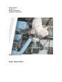
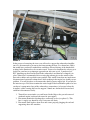
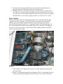
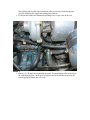
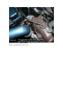
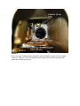
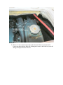
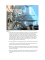
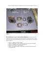
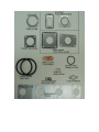
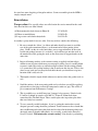
PART 1
Step by Step Procedure for Removal 135/150 Manicoolers (Long)
This is written for the ‘least common denominator’ mechanic. Many of the comments
here are compiled from some of comments on the Bayliners Owners Club and additional
references to posts on that forum are included.
1. My boat has had the port engine retrofitted with a water-cooled turbo. I’ve tried to
document removal of the water cooled turbo as well but there are perhaps some
differences between this retrofit and stock 150’s.
2. This procedure is written in such that it can be used to remove the cooling bundle
only or the entire manicooler assembly (housing and cooling bundle).
3. It is also written such that the most basic mechanic can follow it, perhaps too
much so for many of the veteran Hino mechanics on the BOC forum. I think this
work can be intimidating to many who are not familiar with diesel engines or
engines in general. I hope this helps those potential mechanics. No special tools
are required for this effort except a torque wrench during the reinstallation phase.
This statement assumes that the cooling bundles will be tested ‘by others’. Testing
can be done yourself if you wish. I bought a Stant radiator test kit and made a
bundle tester similar to the one shown by Steve3218 in his post which is
referenced later in this document.
4. To be technically correct, I am not actually calling out bolt sizes. So when I say
remove four 14mm bolts, I’m really calling out the socket/wrench size required
for removal, not the actual bolt shaft diameter.
5. Use this document at your own peril as I’m only sharing my experience having
done this twice. Most importantly- be sure to properly secure all hoses associated
with riser removal as it will vary boat to boat and failure to do so can have
significant repercussions (like sinking your vessel).
Before starting: If possible, spray the nuts shown in Photo 4 with rust penetrant 24
hours in advance to help in removal. Also, in hindsight, I knew I was going to change my
oil filter (I have the canister with element type) as I had just adjusted the valves. If you’re
going to do so anyway, then go ahead and pull the filter and element off and cover the
filter base with plastic. This will give easy access to the bolts at the bottom of the bracket
as shown in Photo 10.
Tools & Materials Required:
Screwdrivers
3/8 and ½ drive ratchets, sockets, and extensions
Gasket Maker
Thread Sealant
Gasket set
Baggies with marker
Optional: Coolant Hoses
Photo 0 General layout
Remove Exhaust Risers:
Photo 1
In the process of removing the risers you will need to support the exhaust hose/muffler
once it is disconnected to prevent water from entering the boat. I’ve shown how I did it
but would have preferred a method that would have allowed closing of the hatch while
waiting for the manicooler to be ceramic coated. You need to determine the safest way to
do this for your boat as an improper approach can sink your vessel. I purchased a 4”
PVC plumbing cap that I inserted inside the exhaust hose and then hose clamped it in
place. Others have recommended also covering the exhaust pipe on the outside of the
boat with a rubber end cap which seems prudent. This would assure that any inadvertent
disconnection of an interior exhaust hose while working in the engine bay would pose no
problem. You will also have to disconnect the shaft log water supply line. If you only do
the interior cap as I did, then examine the entire length of the hose/muffler path to be sure
you haven’t compromised any of the exhaust hose connections (at least any below the
waterline) while securing the hose for support. I found one of mine had loosened and
could have disconnected easily.
1. Turn off raw water intake sea cock located in the bilge at the port aft corner of
starboard engine (starboard aft corner for port engine).
2. Disconnect manicooler discharge hose connected to riser (see photo 2) . This
hose’s supply was shutoff in step 1 but water will drain.
3. Disconnect shaft log hose from riser and secure properly plugging the end and
supporting above the waterline.
4. Disconnect hose clamp on muffler side (the exhaust hose should already be
properly supported at this time to allow hose disconnection)
5. Unbolt the riser (4) 14 mm bolts from turbo and work riser loose from the hose
end. This may take some work as the rubber may have adhered to the riser. I used
a screwdriver to work around circumference but care must be taken to not damage
the rubber hose as even if you’re going to replace it, you can use it as a spare.
Drain Coolant:
Follow standard procedures for draining coolant. Be sure to open and drain the upper
coolant drain valve (see photos 7 & 10 for location) as well as the lower drain valve
(which is part of the alternator support bracket). I didn’t do the upper on the first
manicooler and regretted it as there was a significant amount of coolant remaining. On
the second manicooler I battled unscrewing the drain valve to find that it was plugged
anyway. I cleared it using a piece of wire but not before adding coolant to my bilge in
order to prevent future freezing.
Photo 2
1. Loosen clamps on air supply tube, remove (2) 14 mm support bolts underneath
and remove tube
2. Remove 14 mm turbo oil supply banjo fitting bolt. This is a metal supply tube and
it started to turn when breaking loose the bolt. I put a screw driver between the
banjo fitting tube and the turbo housing in order to prevent it from turning and
possibly damaging the supply tube during bolt removal.
3. Go ahead and remove the manicooler discharge hose to get it out of the way
Photo 3
1. Remove (2) 10 mm bolts connecting the turbo oil return flange to the underside of
the turbo housing. Put a small piece of paper towel in the oil tube to prevent dirt
from dropping in during the next steps.
Photo 4
1. Remove (2) 14 mm nuts on bottom of ‘elbow’ adapter flange attaching it to
support bracket.
2. Per comments on the forum, it makes sense to not break apart the nuts connecting
the turbo to the elbow which will save $25 for a gasket. Remove the (4) 14mm
nuts with jam nuts that connect the elbow to the manifold and remove the elbowturbo assembly.
.
Photo 4A (water cooled turbo)
Remove (2) 30 mm banjo bolts on top.
Photo 4B (water cooled turbo)
Remove (2) 30 mm banjo bolts on bottom.
Photo 5 (this photo is taken from the master berth looking aft at the front of the
starboard engine)
1. Loosen hose clamp on raw water supply hose and disconnect from end cap, hose
may remain in place. As noted, if you’re going to replace hoses this is the time to
do it to allow better access to area for working.
NOTE: If you have the strength or help to remove the manicooler with the cooling
bundle intact, skip to Photo 9 as the following disassembly can take place on the work
bench. Otherwise the following will allow removal of the bundle while leaving the
housing in place.
2. Remove (4) 12 mm cap nuts securing the rear end cap to the manicooler housing
and remove end cap. I removed the large hose in the photo but am assuming you
can gain access to the end cap nut located behind this hose by reaching down
through the small cockpit access hatch above the radiator cap located just outside
the salon door (or in storage area under the flybridge ladder for the port side.
3. Pry out sealing O-ring, do not damage sealing surface while doing so (same as in
Photo 7)
Photo 6
1. Remove (4) 12 mm cap nuts on front manicooler end cap and remove cap. The
cap does not use a typical gasket.
Photo 7
1. You can now see the end of the cooling bundle and the O-ring sealing gasket (it
may not appear round due to being compressed for twenty something years). Pry
out sealing O-ring (do not damage sealing surface while doing so)
2. The bundle can now be removed but will most likely be held in place to a degree
due to mineral deposits from the water. Some have suggested tapping from the
forward end on the end of the tube bundle to drive it out towards the engine
compartment. Care must be exercised in doing so because the tubes shown in the
photo are soldered to the supporting plate holding them and damage to the solder
will allow the salt water to mix with the engine coolant. If significant force is
necessary, cover the end of the bundle with a small piece of wood and tap on the
wood to distribute load across the face of the bundle.
3. Once loosened you can slide the bundle out towards the stern (be prepared as it’s
heavier than you think).
Photo 8
This is the view looking into the manicooler once the bundle is removed (I love digital
cameras!!). Many areas can be examined in this manner but for full examination the
manicooler should be removed.
Photo 9
1. Remove 17 mm coolant temperature tube banjo bolt from top of manicooler.
Loosen the banjo bolt on other end of fitting and rotate it out of the way to avoid
damage during manicooler removal.
Photo 10 (This photo from front of engine and shot by reaching around alternator on
stbd side )
1. Loosen bolts at base of large bracket shown in photo. As stated at the beginning,
if you’re going to replace your oil filter anyway and have the canister with
element type, it may be easier to reach these bolts after removal of the filter
assembly. The other option is to remove the manicooler with these bolts in place
as I did originally but you have a bit more risk damaging the exhaust gasket
(around $75) if you wish to reuse it. Once the manicooler is out these bolts can
then be loosened to facilitate installation by allowing space to get the abovementioned gasket into place without damage.
2. Loosen completely (4) 17 mm upper bolts (long). On my boat the starboard tank
would not allow removal of the bolts from the manicooler housing so they were
pulled back but remained in place during housing removal.
3. Remove (4) 17 mm lower bolts (short) completely. Note: I believe the two center
bolts are longer than those on each end to account for the thickness of the bracket
they must pass through.
4. At this time, the manicooler housing can be removed. It’s relatively heavy given
the cramped space but even more so if you’ve left the bundle in place, so be
prepared.
5. Be sure to plug exhaust ports with paper towels to prevent the ingress of dirt, etc.
Photo 11: This shows a comparison of the air cooled versus water-cooled elbows and
gaskets
Disassembly for ceramic coating and/or inspection: I was lucky on the first
manicooler and every inspection plate bolt came out easily. That was not the case on the
port side (which had been worked/removed previously) as I currently have 5 bolts which
will not come out.
1.
2.
3.
4.
5.
Remove ‘radiator’ cap flange assembly
Remove manufacturer’s plastic emblem in one piece if you wish to reinstall it
Remove coolant hose flange on front of manicooler.
Remove (2) side square inspection plates
Remove (2) bottom rectangular inspection plates. Remove coolant drain valve
from smaller plate.
Photo 12/Table- Gaskets Required:
Many gaskets are called out in the Hino database on the BOC forum. Some members say
you can reuse gaskets but I prefer not to take the chance and just replaced them. Given
the sometimes ridiculous prices for some of the gaskets, I can see the obvious merit in
reusing where possible. The engine block to manicooler gasket seems a very good
candidate for reuse especially given the $75 price tag. Above is what I ordered with
corrected part numbers per invoices from North Harbor in Anacortes. Plan for around the
$200 dollar range for a complete Hino gasket set per engine. If you don’t have the
original risers, Hino hoses will run about $130 per engine. With original risers expect
around $160 or so. These prices are only for the hoses for the coolant, the two raw water
hoses I was able to match at Napa Auto. I have to give extremely high marks to North
Harbor who were absolutely fantastic about my returning parts without a restock fee.
They even did so after an amount time that most businesses wouldn’t have accepted
returns. I could not find cheaper prices (it’s all relative) at the local Hino truck dealership
in Seattle or elsewhere.
** The elbow to turbo gasket can be avoided by simply not separating the respective
parts.
***I stopped by National Marine Exhaust at the boat show and Scott has an equivalent
‘Turbo to Riser’ gasket for $12 (from poor memory) instead of $47 for the OEM which
he stated was more forgiving of irregular surfaces. Seems reasonable given the OEM is
simply stamped metal.
Reinstallation:
Torque values: Few specific values are called out in the service manual for the work
done here but these are what I found:
(8) Main manicooler bolts shown in Photo 10
(4) Elbow to manifold nuts
(4) Large water-cooled turbo banjo bolts
33-36 Lb-Ft
33-36 Lb-Ft
38-43 Lb-Ft
Assembly is pretty much in reverse order. You may wish to consider the following:
1. Be sure to attach the ‘elbow’ (or elbow and turbo should you want to avoid the
cost of the gasket mentioned above) to the manicooler before putting it into
place. I didn’t on the air cooled unit (there was no support bracket on the water
cooled unit perhaps because it’s a retrofit?) and could not get onto the studs of
the manicooler while getting the studs on the elbow into its support bracket at the
same time.
2. Inspect all mating surfaces as the ceramic coating as applied can form ridges
similar to runs in paint, which may prevent proper seating. I used a sanding block
to remove such ridges and was somewhat surprised how soft the coating actually
is. I assume that heat cycling hardens it but do not know this for sure. Take a wire
wheel to any studs and you may find bolt hole threads you should run a tap into
but mine didn’t really need it.
3. Thoroughly clean the engine block exhaust area surface where the gasket needs to
seal.
4. Scuff the surfaces of the new coating with steel wool where you will be applying
gasket maker or dressing to allow the compound a surface to grip. This advice is
per a comment from Performance Coatings.
5. This is probably way overkill but given I snapped a few anyway, I kind of wish
I’d ordered a bunch of stainless steel M8 X 1.25 mm X 20 mm bolts from
somewhere like The Bolt Depot. These would replace the inspection plate bolts
that were fairly beat on mine.
6. To save yourself possible headaches, if you’re getting the manicoolers coated,
adequate pressure testing should be performed. Some forum users have found that
after sandblasting and coating that leaks had developed in the housing which you
obviously want to identify immediately. As to testing, search for the thread by
Steve3218 titled ‘W04 manicooler ceramic coating’. Note that he is performing
two pressure tests- 1. The tube bundle themselves 2. The entire assembly which
tests the bundle O-ring seals.
7. Some forum comments indicate that if you’re working by yourself, you may want
to leave the cooling bundle out of the manicooler housing to reduce weight and
make it easier to handle during installation. Others have installed them fully
assembled, which is what I did. One advantage of bench top assembly is easier
adjustment of the end caps and testing for electrical isolation as discussed under
#12 below.
8. I used a ‘gasket maker’ compound (Permatex Ultra Black Gasket Maker) on all
inspection plates. You only finger tighten the bolts until the sealant oozes out and
let sit at least two hours before tightening to final torque values.
9. Be sure to use adequate thread sealant on upper coolant drain spigot where it
screws into the inspection plate as mine was leaking. Someone had used only
Teflon tape. Given I had the plate off, I applied sealant on the interior as well after
screwing it in just to be sure.
10. I snapped 5 bolts on the inspection plates on the unit that had been installed by a
local shop and none on the factory installed bolts- go figure. Use a suitable thread
sealant (not thread-lock) that seals as well as prevents seizing on all bolt threads. I
used Permatex Thread Sealant with PTFE. It comes in a large pot with brush and
you will use a bit given the quantity of bolts in this effort.
11. Also snapped the coolant banjo bolt adjacent to the coolant cap. This is not
stocked by North Harbor and had to come from Japan (see recent posts on impact
of the earthquake on Hino parts availability). I contacted local hydraulic shops but
couldn’t find them. I had to make my own out of a M12 x 20mm x 1.75TP bolt.
Don’t over do it.
12. It is unclear to me that if the conventional wisdom of the forum is correct and that
electrical isolation of the cooling bundle from the manicooler housing is desired,
why Bayliner provided such a tight fit for the housing internal bracing brackets.
After coating, I could not slide the bundles back in and took a drill with grinding
stone bit and ground down the internal bracket edges. I have heard this from other
forum members so it is most likely a common situation. I measured the outside of
the bundle diameter and the inside of the end cap and figure there is a 14/1000
gap to play with but I’m guessing the end cap bolt holes have that much slop
(didn’t measure). I had a heck of a time getting any sort of isolation. When
installing the bundle end caps, do not install one all the way and then attempt the
other. Start both ends and alternately tighten the bolts to bring them in equally
until seated. I had my wife measure with the voltmeter and as I tightened each
end but still had not seated the bolts and I lightly tapped the end cap with a rubber
mallet until I had a reasonably large ohmic value. Small tightening made big
differences as at one time I was reading 45 kohms and did the last few threads of
the bolts and it went to 25 Mohms. Maybe I was just making it harder than it is.
13. If you have clearance issues on the starboard side for the main manicooler side
bolts as I do (and this sounds typical), be sure to insert the long bolts into the
manicooler before positioning in place.
14. Be sure to inspect turbo for blade damage and smooth blade rotation while
removed.
15. After attaching the turbo oil return line but before attaching the turbo oil supply
line on top, pour in a little motor oil to lubricate the turbo at startup, especially if
she has been sitting a long while.
16. Take this opportunity to inspect all hoses. I found that my turbo oil return hose
was significantly damaged. This hose is exposed to high temperatures and may
require a high temperature rated hose for which I’m using the silicon heater hose.
I also found the ‘manicooler to riser’ hose was badly cracked on both engines.
DIESEL BLING BABY! Some do not like the look and paint the ceramic coating but if
you got it- flaunt it!
Review posting at the Bayliner Owners Club on manicooler inspection and cooling
bundle cleaning.
Regardless of engine model, I would think this is the time to do any work on the
starboard side of either engine. For me this included 1. Cleaning all the electrical
alarm/sensor connections around the oil filter canister. 2. Changing the oil filter 3.
Cleaning the bilge area.
Well, I took a shot at it and I’m sure I screwed up in places. Again, use this procedure at
your own peril. Thanks for reading, Dean (Toukow)