1
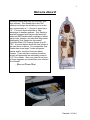
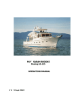
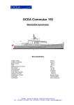
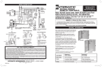
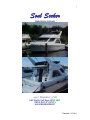
1
Soul Seeker
Operations manual
1997 Bayliner 3788
VHF Radio Call Sign: WDC 5221
USCG DOC # 1127413
Hull # BLB06EDE697
Revised 5/10/2005
2
Welcome Aboard!
We enjoy boating and hope you will enjoy your
time onboard. Soul Seeker has a fast, fuel
efficient hull design that will allow you to cruise
very economically at 7 – 8 knots or speed up to
12 – 17 knots to meet schedules or take
advantage of weather windows. Soul Seeker is
specially equipped with Norscot drip-less shaft
seals and R&D flexible shaft couplings to reduce
salon noise, vibration, and odor from bilge water.
Additionally Soul Seeker has the newest
ColorMax Wide LCD Charting System from SITEX. A second station allows the chart plotter to
be used above or below. For convenience Soul
Seeker has a new larger Tundra refrigerator
freezer and for comfort a Hurricane diesel
furnace. Those that like to explore shorelines
closely will appreciate the adequately powered
11’2” Avon tender. After your cruise let us know
of future upgrades you would like to see onboard
Soul Seeker.
− Steve and Kristen Hiett
Revised 5/10/2005
3
SAFETY GUIDLINES:
• Familiarize yourself with the boat’s systems. This manual and the “Grey Book”
will get you going. For additional information select equipment manuals are in
the salon.
• Familiarize yourself with the charts you will depend on. Use the paper charts to
keep track of your position at all times—stay clear of crab pots, gill nets, rocks,
shoals, old pilings, and kelp beds.
• All crew members should be on constant watch for logs and debris while
underway. Lines of floating debris should be crossed slowly to avoid propeller
damage.
• Know the status of tides, currents, and weather forecasts. Conditions change
fast!
• Do not cruise after dark or in low visibility.
• All crew members should be familiar with VHF Radio operation. Emergencies
are no time to learn.
• Keep body parts away from anchor windlass when operating.
• Know the water depth. Both stations are equipped with depth sounders
BEFORE EMBARKING CHECK SAFETY EQUIPMENT
• Visually inspect security of lines, dinghy & oars, fenders, electrical cords, etc.
• Check anchor for readiness. Note: A smaller spare anchor, chain, and 275’ of
line are located in a bucket in the Lazarette.
• Life jackets are located in the salon under the settee.
• Secure loose objects on deck and below.
• Fire extinguishers are in the galley and forward staterooms.
• Safety flares, and flare gun are located in the drawer under the helm seat.
• First aid kit is in the head locker.
Revised 5/10/2005
4
ENGINE ROOM CHECKS
Caution: When removed, the engine hatches should be securely placed so that
the do not fall on the person in the engine room. Additionally dogs, kids, and
other crew members should be warned or locked out of the salon while the
hatches are open to prevent an accidental fall.
Oil level:
Do not overfill or operate below the “Add” mark
Use only DELO
15/40 w
Transmission fluid
Do not overfill or operate below the “Add” mark
level:
Use only Dextron
ATF
Racor fuel filters:
Check for water or dirt in bowl. Drain into empty oil
See picture below
container or bucket only if necessary.
Propeller shaft
Check level and add as necessary
lubrication:
See picture below
Use only Dextron
ATF
Engine coolant:
Check levels in expansion tanks (forward bulkhead). Add
Use only 50/50
as necessary when engine is cold to bring level to the
green antifreeze
“cold” mark.
Engine cooling raw Valves should be open (handles upward). To check sea
water thru-hull
strainers, first close thru-hull valve. Do not over-tighten
valves:
sea strainer, as brass bolts can strip easily. Open thru-hull
Access through
valve when done, and check for leakage.
lazarette
Fuel line valves:
Engine room rear bulkhead – for normal operation all
See picture below
valves should be in the positions as shown below.
Racor bowl – Shaft seal reservoir
Normal fuel valve alignment
Revised 5/10/2005
5
STARTING ENGINES:
• Master DC battery switch ON (locker in starboard cockpit).
• Turn engine room blower on.
• Start the port engine first (its alternator supplies the starting battery). Turn key
one click – alarm will sound, red and orange lights will be on. When the orange
pre-heat light goes out turn the key to start engines. The red alarm light will
shut off once oil pressure is established (do not continue to run the engine
without oil pressure for more than 15 seconds).
• Raise the engine speed to 1000 rpm to limit the preheat cycling on cold engine.
Note bumping the engine speed to 1400 rpm will initiate charging from the
alternator.
• Reduce engines to idle speed (700-800 rpm) prior to maneuvering.
• Do not allow the engines to idle more than 3 to 5 minutes before getting
underway. 10 or more minutes of idling will cause coking of the combustion
chambers.
• Check oil pressure gauges normal.
• Water temp. Should run 180ºF to 200ºF.
Special Note: Should an engine fail to crank when battery voltage is
normal the problem is probably a sticky neutral safety switch. Try shifting
the transmission. A jumper may be applied on the switch on the
transmission to bypass the function or place both leads on one terminal.
SHUT DOWN
Idle the engines for three to five minutes to cool down. (Note: This is important to
prevent damaging the turbo.)
Turn keys to the vertical off position to kill engines.
TRIM TABS
Trim tabs are intended for corrections to boat trim. Apply button for a few
seconds and then wait for boat to react. The tabs should be up for backing and
docking. The Trim Tab switches are located just below the Lorance depth finder
on the lower helm station.
BATTERIES:
The boat is equipped with one 8D battery for starting both engines and six golf
cart batteries for house loads. The port engine charges the engine starting
battery and the starboard engine charges the house batteries. When connected
to shore power the inverter charges the house batteries and the charger (switch
on A/C panel) charges the starting battery. At anchor you may charge the house
batteries by running the starboard engine at approximately 1400 rpm.
Revised 5/10/2005
6
MAIN SWITCHES:
All main switches are located in stern cockpit locker (starboard side). The battery
parallel switch may be used to boost the starting battery from the house batteries
in an emergency.
MAIN ELECTRICAL PANEL:
DC BREAKER PANEL – The DC master switch should be in the “up” on
position. This will operate all systems. The battery monitor selector maybe used
to check the starting and house batteries. The rocker switches on the panel
operate the fresh-water pump and the engine-room lights (amber lights on when
energized). If the water tank runs dry the water pump will continue to run. Turn
off the rocker switch on the panel immediately.
Special Note: Ensure that the Hurricane diesel furnace is OFF prior to
switching the DC master switch. Cycling power to the furnace while it is
running will severely damage the unit.
WINDLESS POWER – The switch should be off until anchor is needed. A blue
light will illuminate when power available.
TANKWATCH – The red light will be on when the holding tank is filled. The tank
should be emptied at a pump out station before using the head.
WATER TANK LEVEL – The #1 tank is active. Depress the rocker switch to
read tank level. The water tank filler cap is located on the port side walkway
deck. Fresh water hose is located in the lazarette.
Special Note: When the fresh water tank is filled to above full it will
indicate empty until some water is used to bring the instrument on scale.
TRACE RC2000 INVERTER – The meter and controls are located above the AC
panel.
Special Note: House battery voltage may be conveniently monitored by
keeping the Lorance depth sounder ON and checking “Voltage”. This will
also keep you continuously apprised of your depth.
SHORE POWER / AC BREAKER PANEL – The shore power cords are located
in the stern cockpit in the rear storage compartment on the transom. In most
cases use the power cord splitter to power lines one and two masters. Power
cord adapters are located in the drawer next to the TV.
• TURN OFF MASTERS BEFORE CONNECTING TO OR DISCONNECTING
SHORE POWER FROM SHORE POWER.
• Connect cords to boat first, then to shore power.
• After connecting to shore power, turn on master switch and test with the
volt/polarity switch for power and polarity (each side). IF ANY POLARITY
LIGHTS COME ON, DO NOT USE SHORE POWER.
• Breaker switches are marked for the circuit they control.
Revised 5/10/2005
7
HOT WATER SYSTEM:
The hot water tank is heated by two sources, the diesel furnace when underway
and shore power in port. Hot water will hold for several hours without power.
When underway or not connected to shore power turn off the hot water tank’s AC
breaker (the inverter should not power the water heater). Also if you empty the
water tank turn off the water heater AC breaker. The water tank filler cap is
located on the port side walkway deck. Fresh water hose is located in lazarette.
BILGE PUMPS
There are six electric bilge pumps three operate automatically and three may be
operated manually by rocker switches at the helm stations. Note: Should a
pump fail to turn off check that a manual switch hasn’t been inadvertently
turned on at one of the helm stations.
CABIN HEAT
There are two sources of heat for the boat. 1) Electric: Two built-in electric
heaters operate from AC power. Each has a thermostat to control heat. One is
located in the main cabin and the other in the forward stateroom. These electric
heaters should be turned off when shore power is not available. 2) Diesel: The
Hurricane diesel furnace may be operated while cruising or when shore power is
not available. A thermostat, heater fan three position rocker switch, and the
remote ON / OFF RESET control with LED indication are located at the end of
the galley counter. Turn the heater on; set the thermostat above current
temperature and within a few minutes turn the heater fan on either high or low
speed (LOW –OFF – HI switch located at the end of the galley counter with the
galley lights. The furnace and fan will cycle on the thermostat.
Troubleshooting note: Fault codes are displayed on the LED indicator.
The most common is “7” indicating a “flame out fault”. This is caused by
air in the fuel. The air can be bleed off (see picture) into a bottle and the
fault reset by turning the heater to the OFF/RESET position. The manual
for the heater is onboard. Also there is a summer position that will allow
the furnace to heat hot water only without air heating (see picture). The
heater is accessed via the guest stateroom.
Air bleed valve
Bottle to catch
drips when
bleeding
Inverter
Hot water heater
Winter /
Summer 3-way
valve in heat &
hot water
position. May
be selected to
hot water only.
Revised 5/10/2005
8
ENTERTAINMENT CENTER:
The salon has a 20” flat screen TV and a matching DVD/VCR player. Both are
operated by remote control. There are front panel inputs to plug in your own
electronic games, cameras, etc. The manuals for these units are located on the
inside of the entertainment center doors. A Bose CD/AM-FM stereo is located on
the shelf above the TV. The Bose is also operated only by remote. All are
powered by the inverter battery or by shore power. Please keep track of the
remotes. Note: All “installed” speakers are disconnected.
GALLEY:
PROPANE STOVETOP – The propane tank is located on the bridge under the
main bridge controls. Open the valve to operate. In the galley you must turn on
the propane solenoid control located on the wall next to the sink.
Push down the control knob on the stove and move to the ignite position. Hold
down for 5 to 10 seconds. You should hear a clicking sound and the burner
should light. Release knob and set to desired setting. Turn knob to off position
when done cooking and turn solenoid switch off.
MICROWAVE/CONVECTION OVEN – Operates from inverter battery or shore
power.
REFRIGERATOR – Operates from house battery or shore power. Set
refrigerator to proper temperature to maintain food properly. Remember that the
refrigerator is a major drain on battery power.
BAR-B-QUE:
The Magma propane BBQ is stowed in a bag in the lazarette. The BBQ is to be
mounted on the bracket located on cockpit port side. Care must be taken not
drop any parts overboard while in use. BBQ must be allowed to cool and then
stowed before getting under way.
Carefully screw on a propane bottle to the regulator. Position the lid as a
windscreen along any edge. For lighting, use the long neck propane lighter,
pointing the flame as far down toward the base of the heating element as
possible. Turn the regulator to high. You should hear a “puff” as the gas ignites.
Remove lighter and look through hole to check for flame. (The Magma BBQ
heats up very quickly, and you should also feel heat radiating immediately after
igniting.) Allow burning on high setting for one minute before adjusting to desired
cooking temperature.
Revised 5/10/2005
9
DINGHY:
An 11’2” Avon sport boat is launched and retrieved from the swim step using the
Sea Wise davit system. Launch: Release the bow stabilizer and store. Tilt the
motor up (shifter must be in forward position then tip the motor up and allow it to
come back until it rest on the UP stop). Now crank the gearbox down until the
cable is loose. Tighten the motor bracket and transfer the fuel tank from the
swim step to the dingy. Tilt the motor down by raising it up all the way again and
lowering it to its normal position. Shift the transmission to neutral before trying to
start the engine (you won’t be able to pull the starting rope if the engine is in
gear). Tie the dingy to the boat before you remove the safety pins and release
the Sea Wise latches. You may not be able to release the latches if you load the
boat first. To retrieve the dingy reverse the process.
Warning: Be very careful with your hands around the latches and pivot
points of the Sea Wise davit system. Go slow and get used to it. This is a
very good system but takes some practice.
The engine is a 2 cycle Mercury (sold by Mariner). Fuel mixture is 50:1. Mixing
fuel correctly and using premium fuel if available will enhance operation. Ensure
the tank vent is open prior to operation and closed to prevent water getting in the
fuel when not in operation. Check the carburetor is primed by pumping the bulb
until firm then choke the engine to start. Once the engine is running reduce the
choke and get under way as soon as possible. Two cycle engines do not like to
idle as they will load up the spark plugs.
Do not tow the dingy. Always stow it onboard when not in use to prevent
damage to Soul Seeker or the tender. Use the small fenders to protect the
dingy and other vessels from the Sea Wise brackets as necessary. A
painter should be attached to the bow eye on the dingy when in use and
removed so that it does not get into the props when the dingy is stored.
WINDLASS:
The electric windlass is designed to make anchoring easier. The windlass power
switch is located in the main breaker panel.
The windlass may be used to lower anchor. The operating switches are foot
operated buttons on the bow of the boat. With the anchor clear simply lower the
anchor to the proper depth (Note: the anchor chain is marked every 50’) with
appropriate scope and set by backing down the boat until the anchor is firmly set.
Tie off the anchor to the bow cleat using the stopper located in the forepeak deck
locker (this also acts like a shock absorber).
To retrieve anchor, operate foot switch to lift anchor. Retrieve chain until anchor
approaches within two feet of the bow pulpit and then slowly power the anchor
into its resting position in the bow pulpit. After use turn power to the windless off
at the breaker panel.
NOTE: DO NOT OPERATE SWITCH IF HANDS OR CLOTHING COULD BE
CAUGHT IN WINDLASS!
Revised 5/10/2005
10
ELECTRONICS PACKAGE
NOTE: Owner’s manuals for all electronics are stowed in the salon for reference.
UPPER HELM STATION:
SI-TEX chart plotter mount so that you can move the plotter to flybridge
VHF Radio: Horizon with remote access microphone at the lower helm station.
Lorance digital depth operated by the “accessory” switch
LOWER HELM STATION:
VHF remote access microphone
Furuno GPS linked to SI-TEX chart plotter
Lorance X-65 multifunction Depth Sounder with temperature
Press the power button once to turn on. Press the power button again to
illuminate the panel. The manual is onboard in the salon.
Note: The small toggle switch (labeled) below the X-65 turns the
temperature and speed display on/off.
SI-TEX ColorMax Charting system.
User manual onboard
Autohelm ST 50 radar
Operation: Press the STBY/XMIT key, the unit will warm up for 90
seconds then beep. Press the STBY/XMIT key again to operate then
select the desired range. The manual is onboard in the salon.
Simrad AP12 Autopilot (not recommended for use in the islands)
Operation: Turn on the power (labeled rocker switch). Press the
STBY/AUTO button to switch between manual control and auto pilot. The
manual is onboard in the salon.
Special Safety Warning: Chart plotters, radar, and especially
autopilot are wonderful however they can distract the captain and
have caused collisions and groundings. If you use these devices
ensure you and your crew maintain a careful lookout. Your safety
and the safety of our vessel depend on it!
Revised 5/10/2005
11
ELECTRICAL EFFICIENCIES
Plan your trip around expected charging needs. Of course, this is not an issue if
you plan to be connected to shore power. However, if not, you will need to run
the starboard engine (either in high idle or cruising) or connect to shore power in
order to recharge the house batteries.
Special Note: House battery voltage may be conveniently monitored by
keeping the Lorance depth sounder ON and checking “Voltage”. This will
also keep you continuously apprised of your depth.
Battery charging options:
• Shore power (with inverter/charger turned on)
• Run engines - cruising
• Idle starboard engine (must bump to 1400 rpm to start charging – check volt
meter) while anchored or moored without shore power.
Note: The starter battery is not negatively affected by usage of the
“house” batteries. Therefore, no matter how low your “house” battery
bank, the engines should start with the isolated starter battery. If your
starting battery should die you can parallel to the house battery with the
switch located in the cockpit battery switch locker, starboard side.
The refrigerator is typically the largest consumer of power. To conserve, set to
lowest satisfactory temperature setting, and/or switch off at night. Control is
located inside the refrigerator. It should stay cold enough during the night without
power, acting as an icebox during the cooler nights. Also, keep refrigerator full
so there is less empty space requiring cooling.
Avoid unnecessary “guzzlers,” or at least be aware of their electrical draw.
Examples:
• Microwave: 100 amps (preferable to use for quick jobs rather than actual
cooking)
• Toaster: 80 amps
• Leaving lights on (i.e., dinette light = 5 amps; 5 x 12 hours = 60 amp hours)
Turn off unnecessary electronics when not in use.
By taking these simple precautions, you can enjoy the amenities and comforts of
Soul Seeker’s systems, while minimizing the need to charge or hook-up to shore
power.
Bon Voyage …and please let us know of suggestions that you have
regarding the operation of SOUL SEEKER.
Revised 5/10/2005