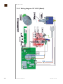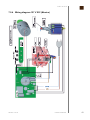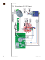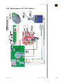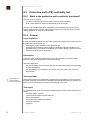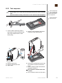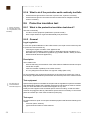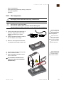
1
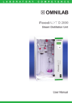
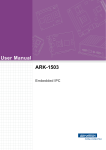
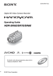
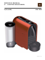
SERVICE MANUAL
U - COFFEE MACHINES
U (C and D)
C50 / D50
Version 1.2 en
CONTENTS
1 General safety notes .........................................................................................5
2 Main components ...............................................................................................6
2.1
Overview ............................................................................................................ 6
2.2
Interior view........................................................................................................ 7
2.3
Fluid system ....................................................................................................... 8
3 Technical data .....................................................................................................9
3.1
Rating plates ...................................................................................................... 9
3.1.1 Examples of brand specific rating plates ..................................................9
3.1.2 Rating plate details (example) ................................................................10
3.2
Technical specifications.................................................................................... 11
3.2.1 Dimensions and weight & size ................................................................13
4 Operation............................................................................................................14
4.1
General information.......................................................................................... 14
4.2
Status indication ............................................................................................... 14
4.3
Machine modes................................................................................................ 17
4.4
Empty water system......................................................................................... 19
5 Maintenance ......................................................................................................20
5.1
Descaling ......................................................................................................... 20
5.1.1 Descaling procedure ...............................................................................20
5.2
Cleaning procedure.......................................................................................... 22
6 Troubleshooting ...............................................................................................23
6.1
Check list.......................................................................................................... 23
7 Repairs ................................................................................................................25
2
7.1
Safety instructions............................................................................................ 25
7.2
Repair and mounting tips ................................................................................. 25
7.3
Tools and accessories...................................................................................... 26
7.4
General disassembly........................................................................................ 27
7.4.1 Prepare coffee machine for disassembly ................................................27
7.4.2 Remove cover.........................................................................................28
7.4.3 Remove front cover and drop stop..........................................................29
7.4.4 Remove slider chassis and slider unit.....................................................30
7.4.5 Remove pivot bottom, cable bracket, power cable .................................32
7.4.6 Remove electronic device.......................................................................33
7.4.7 Remove flowmeter (FM) PCB .................................................................34
7.4.8 Remove high pressure connector ...........................................................35
7.4.9 Remove pump.........................................................................................35
7.4.10Remove brewing unit device and steam cover .......................................36
7.4.11 Remove BU housing and gear wheels....................................................37
7.4.12Remove thermoblock and capsule cage .................................................39
U service manual
Version 1.2 en
7.5
Wiring diagrams ............................................................................................... 40
7.5.1 Wiring diagram 220 V - 240 V IEC ......................................................... 40
7.5.2 Wiring diagram 120 V UL (USA / Canada) ............................................. 41
7.5.3 Wiring diagram 127 V IEC (Brazil).......................................................... 42
7.5.4 Wiring diagram 127 V IEC (Mexico) ....................................................... 43
7.5.5 Wiring diagram 100 V IEC (Japan) ......................................................... 44
7.5.6 Wiring diagram 110 V IEC (Taiwan)........................................................ 45
8 Function tests ................................................................................................... 46
8.1
Safety instructions ........................................................................................... 46
8.2
Required equipment ........................................................................................ 46
8.2.1 Overview................................................................................................. 46
8.3
Measure coffee temperature............................................................................ 47
8.4
Tightness and leakage checks........................................................................ 48
8.4.1 Preparations ........................................................................................... 48
8.4.2 Test run ................................................................................................... 49
8.5
Protective earth (PE) continuity test ................................................................ 50
8.5.1 What is the protective earth continuity test about? ................................. 50
8.5.2 General ................................................................................................... 50
8.5.3 Test sequence ........................................................................................ 51
8.5.4 What to do if the protective earth continuity test fails ............................. 52
8.6
Protective insulation test .................................................................................. 52
8.6.1 What is the protective insulation test about? .......................................... 52
8.6.2 General ................................................................................................... 52
8.6.3 Test sequence ........................................................................................ 53
8.6.4 What to do if the insulation test fails ....................................................... 54
9 Explosion drawings......................................................................................... 55
9.1
C50 Explosion drawing .................................................................................... 55
9.2
D50 Explosion drawing .................................................................................... 56
10 Parts list ............................................................................................................. 57
10.1 Nespresso C50 and D50 ................................................................................. 57
Version 1.2 en
U service manual
3
PREFACE
Please keep this
manual together with
the corresponding
service documentation.
This way you are assured
to have the necessary
information.
The purpose of this service manual is to provide the service personnel with all necessary
information with regards to correct handling, maintenance and repair of the U coffee
machines C50 and D50.
This manual should be used by the technicians as a valuable aid to guarantee the
permanent readiness for use of the machines. In order to take full advantage of all the
functions, it is absolutely necessary to follow the instructions in this manual.
Only use original spare parts from your official supplier for maintenance and repair work.
Spare parts lists and exploded drawings are subject to change. To optain the last
version, please contact your official spare parts supplier.
Access is restricted
and can be obtained
by asking your
Nespresso technical
contact person.
Visit the Nespresso technical website periodically to check for upgrades, technical
modifications, counter measures etc. for these coffee machines:
https://business.nespresso.com
CONTENT UPDATES
Version 1.0
•
First released service manual version, in English only.
Version 1.1
•
Updated version including several corrections, in English only.
•
Change machine name from Pulse to U
•
Update of several drawings
•
Modified operating procedures for the following machine modes:
-
Brewing mode / programming mode
Descaling mode
Emptying mode
Resetting mode
Version 1.2
•
4
Function test added: Tightness and leakage checks
U service manual
Version 1.2 en
GENERAL SAFETY NOTES
1
GENERAL SAFETY NOTES
The repair of these machines can only be performed by Nespresso approved after-sales
centers and technicians, using suitagble tools and original spare parts and taking into
account the national safety regulations.
Risk of fatal electrical shock and fire!
Mains voltage inside the coffee machine.
•
•
•
Unplug appliance before cleaning.
Never clean wet or immerse plug, cord or appliance in any fluid.
Disconnect the mains plug before disassembly - the appliance must
be free of voltage.
As an additional safety measure, the use of a residual current device (RCD), also called
a ground fault circuit interrupter (GFCI), in the repair centre is highly recommended.
This device does
not protect against
electrical shock due to
contact with both circuit
conductors.
1
RESET
2
Example illustrations
of typical devices.
TEST
Use a GFCI with a trip
level of 4 - 6 mA (USA)
resp. a RCD with a trip
level of 15 - 30 mA (Europe).
A trip level above 30 mA
provides only very limited
protection against harm
from an electric shock.
3
RESET
4
1) RCD protected socket-outlet
2) Plug-in RCD unit
TEST
3) GFCI socket
4) Plug-in GFCI
Danger of burns!
Hot parts and water under pressure inside the coffee machine
(particularly in the thermoblock).
•
Let coffee machine cool down before cleaning or disassembly.
Version 1.2 en
U service manual
5
MAIN COMPONENTS
2
MAIN COMPONENTS
2.1
Overview
1 (Lungo, 110 ml)
1 (Espresso, 40 ml)
1 (Ristretto, 25 ml)
2
8
7
3
6
4
5
1)
2)
3)
4)
6
Capacitive touch area
Slider for capsule insertion slot
Used capsule container and drip tray
Removable cup support and drip grid
U service manual
5)
6)
7)
8)
Coffee outlet
Swivel water tank arm
Water tank
Water tank lid
Version 1.2 en
MAIN COMPONENTS
2.2
Interior view
5
6
7
3
4
8
9
2
1)
2)
3)
4)
5)
1
Low pressure connector for water tank
Flowmeter
Steam cover
Drop stop
Thermoblock
Version 1.2 en
6)
7)
8)
9)
BU housing
High pressure connector
Motor
Pump
U service manual
7
MAIN COMPONENTS
2.3
Fluid system
5
1
6
4
7
8
2
3
9
10
11
4
3
1
1)
2)
3)
4)
5)
6)
8
2
Water tank
Flowmeter
Pump
High pressure connector
Thermoblock
Capsule cage
U service manual
5
TB
6
BU
7
9
10
11
7) Coffee outlet
8) Drop stop
9) Capsule container
10) Drip tray
11) Cup support
Version 1.2 en
TE C H N I C A L D A T A
3
3.1
TE C H N I C A L D A T A
Rating plates
3.1.1 Examples of brand specific rating plates
The rating plate can
be found at the bottom of the coffee
machine.
This overview shows
examples of various
brands and is subject
to alterations.
Version 1.2 en
U service manual
9
TE C H N I C A L D A T A
3.1.2 Rating plate details (example)
1
2
3
4
5
6
7
8
9
10
11
X
12115 C50 j 0440 782 07 X
1)
2)
3)
4)
Brand name
Voltage and power rating
Place of manufacture
National approval sign of Russia
(GOST R)
5) Conformity with RoHS guidelines
(lead free solder, etc.)
6) Barcode
7) Serial number
8) Machine type
9) Article number of the rating plate
10) Special disposal icon
(do not dispose with ordinary waste)
11) Sign of conformity (CE)
Decoding the alphanumeric serial number
By decoding the date
of production and
machine type, the
coffee machine can be
identified exactly.
Example:
12115 C50 j 0440 782 07 X
Checksum
Color version
Type of mains plug
Mains voltage
Distributing partner
Incremental number per production day
Manufacturing plant
Manufacturer designation of the machine type (C50)
12115 ... Date of production
(12 = year 2012, 115 = 115th day of the year)
10
U service manual
Version 1.2 en
TE C H N I C A L D A T A
3.2
Technical specifications
Mains voltage ranges
- Europe, RU, AU, CN, KR, SG, HK, ME, ZA, IL, BR, AR ............. 220-240 V, 50/60 Hz
- USA, Canada ...................................................................................... 120 V, 50/60 Hz
- BR, MX ............................................................................................... 127 V, 50/60 Hz
- Japan ................................................................................................. 100 V, 50/60 Hz
- Taiwan..................................................................................................... 110 V, 60 Hz
Approvals
EuP standard
CE, UL "for USA and Canada", PSE, Gost R, Ctick,
CCC, KTL, SPRING, SASO, SABS, ISI, IRAM, NOM
The coffee machine is EuP 2013 compliant
Power consumption
220-240 V mains voltage ..................................................................... approx. 1’260 W
EuP ... Energy using
Products
See commission regulation no. 1275/2008 of the
European Union.
100/110/120/127 V mains voltage......................................................... 1’160 - 1’370 W
Power consumption of coffee machine main components
(for all voltages and frequencies)
Thermoblock ..................................................................................................... 1’200 W
Pump...................................................................................................................... 60 W
Energy consumption (CECED / FEA 2009 method)
Energy efficiency class level ..............................................................................A - 40%
Daily energy consumption.................................................................................... 76 Wh
Annual energy consumption .............................................................................. 28 kWh
Pump
Pump pressure
- Max. permissible .................................................................................... 20 bar ± 3 bar
- During coffee preparation (depending on the type of coffee)........................ 9 - 16 bar
Capacities
Water tank ...................................................................................................approx. 0.8 l
Tray water capacity ...................................................................................... min. 100 ml
Advised water tank
capacity to avoid
spilling.
Capsule container .......................................................................... approx. 10 capsules
Version 1.2 en
U service manual
11
TE C H N I C A L D A T A
Volume of prepared coffee
- factory settings
Small cup "Ristretto ..................................................................................... 25 ml (±7%)
Small cup "Espresso" .................................................................................. 40 ml (±7%)
Large cup "Lungo"..................................................................................... 110 ml (±7%)
- customer settings
Programmable setting range ........................................................................ 20 - 200 ml
Environmental conditions
Operating temperature ............................ + 5 °C up to + 45 °C (+ 41 °F up to + 113 °F)
Storage temperature................................... - 25 °C up to + 65 °C (- 13 °F up to 149 °F)
Altitude ............................................................................up to 2’500 m above sea level
Humidity ................................................................................................... no restrictions
Various data
Preheating time .......................................................................................approx. 25 sec
Automatic shut off time ................................................................ after 9 min of non-use
Safety temperature (electronically controlled) ....................................... 120 °C (248 °F)
Safety temperature (thermal cut-off) ..................................................... 167 °C (333 °F)
Coffee temperature at outlet............................................86 °C ± 3 °C (187 °F ± 5,4 °F)
Descaling temperature .................................................................setting 70 °C (158 °F)
12
U service manual
Version 1.2 en
TE C H N I C A L D A T A
3.2.1 Dimensions and weight & size
Dimensions in [mm].
202
115
138
88
251
366
Dimensions (length x width x height) ............................................ 366 x 115 x 251 mm
Distance drip grid - coffee outlet: .............................................88 mm (Espresso mode)
Distance bottom coffee outlet: ............................................. 138 mm (Macchiato mode)
Power cable length .............................. min. 0.8 m (depending on national regulations)
Weight (without water) ................................................................................approx. 3 kg
Version 1.2 en
U service manual
13
OPERATION
4
OPERATION
4.1
General information
For an overview of operational controls see “Main components” on page 6.
For basic operation of the machine such as preparing a coffee and other related information, refer to the user manual.
4.2
Status indication
According to the following table the status of the coffee machine is shown by
- 3 capacitive sensors on MMI PCB
Machine
status
Off
State events
All elements off
All 3 LED’s blink together
Error
2Hz, 3 times every 2 sec.
electronic
Lungo
off
Espresso
off
Ristretto
off
blinking 2Hz, blinking 2Hz, blinking 2Hz,
3 times every 3 times every 3 times every
2 sec.
2 sec.
2 sec.
All 3 LED’s blink
alternating in direction
front (1st Lungo 0.5 sec,
2nd Espresso 0.5 sec, 3rd
Ristretto 0.5 sec)
on 0.5 sec
off 1 sec
All 3 LED’s blink
alternating in direction
No water back (1st Ristretto 0.5 sec,
2nd Espresso 0.5 sec, 3rd
Lungo 0.5 sec)
off 1 sec
on 0.5 sec
Stuck
capsule
off 0.5 sec
on 0.5 sec
off 0.5 sec
off 1 sec
on 0.5 sec
Heat up
Blinking 1Hz on most
frequently used cup size
of the last 10 coffees,
Espresso when machine
is new. Change to user
selection when other
capactitive area is touched
Blinking 1Hz Blinking 1Hz Blinking 1Hz
or off
or off
or off
Ready
Steady light on most
frequently used cup size,
Espresso when machine
is new; or on user
selection when a
capacitive area has been
touched. Switch to most
frequently used cup size
after each coffee
Steady or off Steady or off Steady or off
Brew
Ristretto
14
LED’s
Steady on Ristretto
U service manual
Off
Off
Steady
Version 1.2 en
OPERATION
Machine
status
State events
LED’s
Lungo
Espresso
Ristretto
Brew
Steady on Espresso
Espresso
Off
Steady
Off
Brew
Lungo
Steady
Off
Off
Steady on Lungo
4 sec.
Steady on cup size that
after brew has been brewed
Steady or off Steady or off Steady or off
Rinse
All LED’s steady on
Steady
Descaling ready
All LED’s blinking
together 2Hz
Blinking 2Hz Blinking 2Hz Blinking 2Hz
Descaling pump
on
All LED’s blinking
together 2Hz
Blinking 2Hz Blinking 2Hz Blinking 2Hz
Descaling pump
off
All LED’s blinking
together 2Hz
Blinking 2Hz Blinking 2Hz Blinking 2Hz
Emptying Espresso On 0.5sec (after
&T
6 sec of pressing touch)
>115°C
(confirmation)
off
Steady
Steady
On 0.5sec
off
Emptying
Lungo and Ristretto blinking together 1Hz
Blinking 1Hz Off
Overheat
All blinking together 1Hz
Blinking 1Hz Blinking 1Hz Blinking 1Hz
Espresso On 0.5sec
Off
Switch
Auto off
time after
30min
Blinking 1Hz
On 0.5sec
On 0.5sec
Off 0.5sec
On 0.5sec
Off 0.5sec
On 0.5sec
Off
Switch
Auto off
Espresso On 3 x 0.5sec
time after
9 min
Off
Factory
setting
Ristretto On 0.5sec
Off
Off
On 0.5sec
Switch to
power off
Ristretto, Espresso and
Lungo together On 0.5sec
On 0.5sec
On 0.5sec
On 0.5sec
Version 1.2 en
Off
U service manual
15
OPERATION
Machine
status
16
State events
LED’s
Lungo
Espresso
Ristretto
ProgramRistretto & Espresso On
ming
0.5sec (confirmation)
Lungo
Off
On 0.5sec
On 0.5sec
ProgramRistretto & Lungo On
ming
0.5sec (confirmation)
Espresso
On 0.5sec
Off
On 0.5sec
ProgramEspresso & Lungo On
ming
0.5sec (confirmation)
Ristretto
On 0.5sec
On 0.5sec
Off
U service manual
Version 1.2 en
OPERATION
4.3
Machine modes
This table helps to understand the operating modes of the U coffee machines:
Machine mode
1 Heat up mode
2 Self test mode
3 Ready mode
4a Brewing mode
4b Volume brewing
mode (programming cup size)
5 Descaling mode
Version 1.2 en
Enter mode
Actions
Heats up thermoblock
to ready temperature
Every time after switch90 °C within 30 sec
ing on machine
without overshooting
target temperature
Tests:
• NTC short circuit
• NTC connected
Every time after switch• Checks if thermoing on machine
block reaches ready
temperature within
2 min after switch on
• After heat up and self
test mode was ok
• After brewing or
volume brewing
Keeps thermoblock
coffee
temperature at 90 °C
• After reset mode
• After leaving
descaling mode
Exit mode
e.g. switching off
machine
e.g. switching off
machine
e.g. switching off
machine
• Press and release
any coffee button
Brewing mode:
when machine is in
• Press and release
brewing mode or
any coffee button
automatic exit given
by the flowmeter
Programming mode:
• Release corre• Open the slider
sponding coffee
• Press and hold any
button when
coffee button for
machine is in
more than 3 sec
programming mode
• Switch off machine
• Press and hold the 3
• Regulates temperacoffee buttons for at
ture to 55 °C (after
• Switch on machine,
least 3 sec
pump was started)
wait until ready
Note: When machine is
• Stops and starts
• Press and hold the 3
switched off during any
pump with any coffee
coffee buttons for at
descaling mode, then it
button, no volume
least 3 sec
goes to descaling
brewing in descaling
mode ready state after
mode
next switch on
U service manual
17
OPERATION
Machine mode
6 Emptying mode
(evaporing)
Enter mode
1) Switch on machine
2) Remove the water
tank
3) Open the slider
4) Press and hold the
Ristretto and
Lungo controls
together for at
least 6 sec. The
other control
flashes for confirmation
5) Close the slider to
start the procedure
Actions
Exit mode
1) Starts pump
2) Stops pump after
10 sec
3) Heats up thermoblock to 105 °C
(100% power)
4) Switches off therSwitch off machine
moblock
5) Switches off
machine
6) Blocks machine for
10 min
• Resets programmed
volumes to factory
• Switch on machine
settings (Ristretto
• Press and hold the
25ml, Espresso
Espresso and Lungo
40ml, Lungo 110ml) Proceeds with self test
7 Resetting mode
controls together for
• Reset also the auto- mode automatically
at least 4 sec. The
matic off mode to
other control flashes
9 min + the most
for confirmation
frequently used cup
size to espresso.
• Switch off machine
8 Auto switch off mode
after 9 min resp.
Automatically after a
(factory setting of 9 min
30 min if no coffee is
certain period of noncan be changed to
brewed or 9 min
use
30 min)
resp. 30 min after
last brewed coffee
Automatically by folMachine indicates faillowing failures:
ure with blinking coffee
9 Failure mode
a) NTC short circuit
When failure is fixed
buttons as long as the
b) NTC not connected
failure is present
c) Heat up too slow
18
U service manual
Version 1.2 en
OPERATION
4.4
Empty water system
After every operation, some water (max. 25 ml) remains in the coffee machine. Therefore the water system must be emptied
- if the coffee machine will not be used for a long time
- as antifreeze measure
- for repairs and shipment.
After this procedure,
the coffee machine
will not be ready for
approx. 10 min (until the
thermoblock cools to below
100 °C ).
2
1
3
2
1
1) Remove the water tank. Place a
container under the coffee outlet.
2) Open slider
3) Press and hold the Ristretto & Lungo
controls together for at least 6 sec.
The other control flash for confirmation. Then close the slider to start procedure.
4) Machines turns to Off mode automatically when empty.
Version 1.2 en
U service manual
19
MAINTENANCE
5
5.1
MAINTENANCE
Descaling
Only use Nespresso descaler (5034) or Nespresso descaling kit
(3035/CBU-2) – never use vinegar!
Descaler can damage casing and surfaces.
Immediately clean drops of descaling solution.
5.1.1 Descaling procedure
Need to descale depending on water hardness:
soft: 0-17fH / 0-9dH = descale after 4’000 cups
medium: 18-35fH / 10-19 dH = descale 2’000 cups
hard: over 36fH / over 20dH = descale after 1’000 cups
Duration approximately 15 minutes
0.5 l
Observe the safety
instructions on the
descaler package.
Use a container with a
capacity of min. 1 l.
20
1) Empty the drip tray and the used
capsule container.
2) Fill the water tank with 1 unit of Nespresso descaling liquid and add
0.5 L /17 oz of water.
3) Place a container (minimum volume:
0.6 L / 20 oz) under the coffee outlet.
4) Activate the machine by either pushing
the slider or one of the cup selection
touches
5) Blinking light: heating up.
6) Steady light: ready
7) To enter the descaling mode, push all
the 3 controls simultaneously for at
least 3sec. A short beep will confirm
this. The control area will start blinking.
U service manual
Version 1.2 en
MAINTENANCE
8) If slider is closed, push any control to
start descaling. If slider is open, close
it to start descaling. Machine stops
when water tank is empty.
9) Refill the water tank with the used descaling solution collected in the container and touch any control to repeat
the procedure.
10) Empty and rinse the water tank, capsule container, drip tray and cup support thoroughly. Fill water tank with
potable water.
11) When ready, touch any control to rinse
the machine. Machine will stop when
done.
12) To exit the descaling mode, push all
the 3 controls simultaneously for at
least 3sec. A short beep will confirm
this. The machine is now ready for use
Version 1.2 en
U service manual
21
MAINTENANCE
5.2 Cleaning procedure
Risk of fatal electrical shock and fire!
Never clean wet or immerse plug, cord or appliance in any fluid.
Unplug appliance and let it cool down to avoid burns.
Never use brushes
and/or cleaning
agents that contain
aggressive or chemical
components resp. solvents.
Do not put any part in a
dishwasher.
Use only a damp cloth or
sponge and a mild cleaning
agent if necessary
1) Do not use any strong or abrasive
cleaning agent or solvent cleaner. Do
not put in a dishwasher.
2) Never immerse the appliance or part
of it in water.
Do not use a brush the water tank can be
scratched.
3) Clean the coffee outlet regularly with a
damp cloth.
22
U service manual
Version 1.2 en
TROUBLESHOOTING
6
6.1
TR O U B L E S H O O T I N G
Check list
Check
Error symptoms
Measure /
repair work
Further measures /
repair work
YES - replace housing parts if
1.1 Housing parts bronecessary
ken or damaged
NO - continue
1 Check the coffee
machine for visiYES - replace power cord
ble damage
1.2 Power cord dam- NO - connect power cord of
machine to the mains and conaged
tinue
2.1 Cup support with
capsule and waste
water container
does not remain in
fitting position
2.2 Slider malfunction
YES - Empty the capsule conYES - slider does not close or tainer
close properly
YES - Check that no capsule is
NO - continue
blocked inside the machine
NO - replace slider unit
2.3 Capsule is not
ejected correctly
YES - replace brewing unit
NO - continue
3.1 Water tank leaks
YES - replace water tank
NO - continue
2 Check mechanical components
3 Fill water tank
NO - replace waste water conYES - check if waste water
container has its metallic plate tainer.
for magnetic mounting
NO - continue
a) YES - power cord is okay
(loose connection)
After an initial inspection in accordance
with this check list,
errors are quickly found and
corrected with the appropriate measure.
Therefore, adhere to the
sequence of the check list.
Repair every occurring error
and work the check list
through until it is completed.
YES - continue
NO - replace power cord
b) YES - On/Off switch has typ- YES - continue
ical switching noise
NO - replace functional block
c) YES - pump works (press a
4.1 Coffee machine is coffee button)
not working
4 Move Machine to
(does not function) d) YES - both coffee buttons
are working
power on to perform automatic
e) YES - fine wire fuses or triac
self test
on thermoblock defective
f) YES - wiring is okay
NO - continue with point 4.2
YES - thermoblock is hot
4.2 Both coffee buttons NO - self test ok - continue
are blinking 3x fast
YES - continue with point e)
NO - continue with point d)
YES - replace pump
NO - replace functional block
YES - replace thermoblock
NO - continue
YES - replace functional block
NO - replace defective cables
YES - switch off/on coffee
machine and check again
NO - replace thermoblock or
functional block
YES - a) water system is empty YES - fill the water system
NO - continue
YES - b) coffee machine is cal- YES - descale coffee machine
cified
(see page 20)
NO - continue
5 Rinse coffee
machine
5.1 No water at coffee YES - c) pyramide plate
outlet
blocked
YES - d) flowmeter blocked
YES - replace brewing unit
NO - continue
YES - clean or replace flowmeter
NO - continue
YES - e) pump cannot produce YES - replace pump
sufficient water pressure
NO - continue
Version 1.2 en
U service manual
23
TROUBLESHOOTING
Check
Error symptoms
6 Measure coffee
6.1 Temperature is too
temperature durlow (below 83°C)
ing coffee preparation (see page 6.2 Temperature too
47)
high (over 89 °C)
7.1 Hose connections
leak
7 Check for leakage 7.2 Brewing unit leaks
and sufficient flow
rate
7.3 Rate of flow not
within standard
range (60-120ml in
30 sec)
8 Descale coffee
machine
(if necessary)
Measure /
repair work
Further measures /
repair work
YES - descale coffee machine
(see page 20)
NO - continue
YES - replace thermoblock
NO - continue
YES - replace high pressure
connector
NO - continue
YES - replace brewing unit
NO - continue
YES - coffee machine is calci- YES - descale coffee machine
fied
(see page 20)
NO - continue with point 9
NO - replace pump
YES - descale coffee machine
8.1 Coffee machine is
(see page 20)
calcified
NO - continue with point 9
YES - descale and rinse coffee
9 Check water tank 9.1 Particles of calcium
machine again to clean water
contents after desand rust visible in
circuit (see page 20)
caling and rinising
water
NO - continue
10 Final cleaning
(see page 22)
No errors found according to
check list?
YES - inform customer to descale coffee machine periodically and to use the specified
descaling product only.
YES - for more information
please contact Nespresso
Service Division
End of check list
24
U service manual
Version 1.2 en
REPAIRS
7
REPAIRS
These repair instructions
- are based on exploded drawings with position numbers combined with repair and
mounting tips,
- presuppose basic knowledge in repairing Nespresso coffee machines.
7.1
Safety instructions
Risk of fatal electrical shock!
Mains voltage inside the coffee machine.
Disconnect the mains plug before disassembly - the coffee machine
must be free of voltage.
Danger of burns!
Hot parts and water under pressure inside the coffee machine (thermoblock in particular).
Let coffee machine cool down before disassembly.
Only use original spare parts from your official supplier for maintenance
and repair work.
7.2
Repair and mounting tips
These general advices are completed with specific repair tips in this chapter.
Additional information
For components not mentioned in this repair chapter, refer to the chapters "Explosion
drawings" on page 55 and "Parts list" on page 57.
Snap connections
Parts of the case and components of the coffee machine are connected screwless with
latches.
When loosening these latches, proceed with care and patience to avoid
causing any damage.
Designation of spare parts
The components in the following illustrations are indexed with position numbers.
See separate spare parts list for corresponding spare part numbers.
Position numbers are
subject to change
without notice. For
spare part orders, please
check current spare part
drawings in EF webshop
Electrostatic discharge (ESD) protection
The service technician must must observe basic ESD protection measures when
installing a new electronic component.
Version 1.2 en
U service manual
25
REPAIRS
Wiring arrangement
Random changes in the wiring arrangement of the wired model version during a repair
can cause
- electromagnetic interferences,
- squeezed wires,
- insulation defects due to contact with hot parts,
- insulation problems if low and high voltage wires are not separated,
- damage to the functional block.
Protective measures:
• Do not change the thermoblock wiring (thermo fuses and NTC sensor).
•
Refer to wiring diagram when reconnecting cables and wires.
Residual water
•
If it is necessary to pull off hoses, hold ready a small receptacle and a towel to collect
and wipe away leaking water.
•
A special procedure is necessary to empty the fluid system of the coffee machine for
repair or shipment (refer to "Empty water system" on page 19).
7.3
Tools and accessories
With the following assortment of tools, all repairs described can be made:
A bit holder with
appropriate bits can
also be used:
1
2
3
4
.
3.5 mm 8 mm
TX 10 2 mm 3.5 mm 8 mm
1) Torx screwdriver TX10 - 70
2) Flat blade screwdrivers:
size
blade width
00
2 mm
01
3,5 mm
05
8 mm
26
U service manual
3) Pointed pliers
4) Side cutting pliers
5) Receptacle and towel to catch and
wipe away leaking water
Version 1.2 en
REPAIRS
7.4
General disassembly
This subchapter shows
- how to replace the power cord,
- all necessary disassembly steps to gain access to the main assembly (brewing unit,
thermoblock, hydraulic unit and functional block.
7.4.1 Prepare coffee machine for disassembly
1
4
3
•
1. Check and remove any capsule from the brewing unit. Close the slider.
•
2. Empty water system if hoses have to be detached for repair (see “Empty water
system” on page 19).
•
3. Disconnect power plug and let coffee machine cool down.
•
4. Remove all detachable parts from coffee machine:
Cup support, drip grid, capsule container, drip tray, water tank with lid.
Version 1.2 en
U service manual
27
REPAIRS
7.4.2 Remove cover
Use a wrap foil to protect the cover during
service.
1
Take care not to
scratch the surface
and keep the cover at
a safe place.
28
•
Loosen 2 screws on the machine floor (1).
•
Remove the cover by hand.
U service manual
Version 1.2 en
REPAIRS
7.4.3 Remove front cover and drop stop
2
•
Dismantle the front cover clips by hand (1).
•
Remove front cover (2).
•
Dismantle the drop stop clips by hand.
•
Remove the drop stop.
1
To dismantle the drop
stop, the brewing unit
must be closed.
Use a a cordless drill
driver connected to
the motor to close the
unit or, before dismantling
the machine, start a coffee
without a capsule and
remove the power plug during extraction.
Version 1.2 en
U service manual
29
REPAIRS
7.4.4 Remove slider chassis and slider unit
3
2
1
30
•
Plug out the touch pad cable (1)
•
Dismantle the slider-chassis clips with a screwdriver (2).
•
Remove the slider chassis
•
Pull down the blind (slider) during the dismantling of the clips.
U service manual
Version 1.2 en
REPAIRS
3
1
2
4
•
Remove slider unit (1): press forward and upward.
•
Remove touch pad cable (2).
•
Remove touch pad (2).
•
Dismantle slider for removing spring packet (3).
•
Remove the rachets (4).
Assembly checkpoint
Position the slider and spring packet bevor assembly slider-unit.
Position the ratchets and touch pad cable befor assembly slider-chassis.
Version 1.2 en
U service manual
31
REPAIRS
7.4.5 Remove pivot bottom, cable bracket, power cable
2
1
•
Dismantle the clips with a screwdriver (1)
•
Remove the pivot buttom and low pressure connector WT (2).
1
The strain cable
bracket is under tension. Therefore, hold
down the strain relief clamp
with your finger when
unlatching it.
2
•
Remove the cable bracket (1) with a screwdriver and the connection cable (2).
Assembly checkpoint
•
32
Never re-use damaged cables.
U service manual
Version 1.2 en
REPAIRS
7.4.6 Remove electronic device
•
Dismantle the electronic device clip with a screwdriver.
•
Unplug cables and remove electronic device.
•
Remove pump isolation.
•
Plug out low pressure connector pump, pump cables, Motor cables, NTC / Triac
signal cables - XHP 3 connector, triac power cable and STB cable.
Assembly checkpoint
Never re-use damaged cables.
Version 1.2 en
U service manual
33
REPAIRS
7.4.7 Remove flowmeter (FM) PCB
Latch will break if not
handled carefully!
•
Dismantle the electronic device clips with a screwdriver.
•
Dismantle the flowmeter clips by hand and remove flowmeter
Assembly checkpoint
Never re-use a dismantled flowmeter. Assemble a new flowmeter.
34
U service manual
Version 1.2 en
REPAIRS
7.4.8 Remove high pressure connector
•
Remove the high pressure connector by cutting the connector clips.
7.4.9 Remove pump
•
Remove pump support
•
Remove pump.
Version 1.2 en
U service manual
35
REPAIRS
7.4.10 Remove brewing unit device and steam cover
•
Dismantle the brewing unit device clips with a screwdriver.
2
Push the thermoblock to the backside and upward at
the same time.
1
36
•
Remove brewing unit.
•
Dismantle the steam cover clips with a screwdriver and remove steam cover.
U service manual
Version 1.2 en
REPAIRS
7.4.11 Remove BU housing and gear wheels
Use e.g. a cordless
drill driver.
•
Turn worm gear till the stop limit.
•
Lift up the cover once the guides are at the rear, vertically positioned.
Version 1.2 en
U service manual
37
REPAIRS
•
Remove BU housing, bush bearing, gear lever right, gear lever left.
Assembly checkpoint
Right side
left side not ok
•
38
left side ok
left side not ok
Note the correct mounting position for gear lever left (41) and gear lever right (47).
U service manual
Version 1.2 en
REPAIRS
7.4.12 Remove thermoblock and capsule cage
2
1
•
Loosen 2 screws to remove thermoblock and capsule cage.
•
Remove TB sleeve and o-ring seal tb tube.
Version 1.2 en
U service manual
39
REPAIRS
7.5
Depending on
national regulations,
one or two fine wire
fuses are mounted on the
thermoblock.
40
Wiring diagrams
7.5.1 Wiring diagram 220 V - 240 V IEC
U service manual
Version 1.2 en
REPAIRS
7.5.2 Wiring diagram 120 V UL (USA / Canada)
Version 1.2 en
U service manual
41
REPAIRS
7.5.3 Wiring diagram 127 V IEC (Brazil)
42
U service manual
Version 1.2 en
REPAIRS
7.5.4 Wiring diagram 127 V IEC (Mexico)
Version 1.2 en
U service manual
43
REPAIRS
7.5.5 Wiring diagram 100 V IEC (Japan)
44
U service manual
Version 1.2 en
REPAIRS
7.5.6 Wiring diagram 110 V IEC (Taiwan)
Version 1.2 en
U service manual
45
FUNCTION TESTS
8
FUNCTION TESTS
8.1
Safety instructions
Some function tests are performed with an energized, partly opened coffee machine.
Danger of electrocution!
Mains voltage inside the coffee machine.
Do not touch any live part while performing tests.
Danger of burns!
Hot parts and water under pressure inside the coffee machine.
Do not touch any hot parts while checking for leakages!
Always wear protective goggles.
8.2
Required equipment
8.2.1 Overview
Symbolic illustration
of function test equipment.
1
T2
T1
3
2
1
RE
HO
L
LD
MAX
MIN
T1
T1← T2
T2
°C/°
F
RA
NG
E
-200
-328 °C 13
°F
- 24 70°C
98°F
4
S
MEA
5
URE
COM
0Ω A
OP
K/ST
P
DJ
T
LIGH
LOC
1) Electronic thermometer
2) Timer
3) Measuring cup
46
U service manual
4)
Test equipment for protective earth continuity test and protective insulation test
5) Flashlight
Version 1.2 en
FUNCTION TESTS
8.3
Measure coffee temperature
1
10 sec
3
4
2
1) Start coffee machine.
2) Place a measuring cup on cup support.
3) Preheat coffee outlet with hot water:
1. Press Lungo button or close the
slider.
2. Wait 10 sec.
3. Press button again to stop (or pull
the sticker).
4) Empty measuring cup and place it
back on cup support.
5 - 10 mm
6
5
7
T2
T1
1
RE
HO
LD
MAX
MIN
T1
T1← T2
T2
°C/°F
RA
5) Insert capsule (Cosi is best suited).
6) Press the Lungo button again.
NG
E
L
8
-20
0°C
-32
8°F - 1370
- 24 °C
98°F
7) Wait until the measuring cup contains
20 ml of coffee.
8) Then measure the coffee temperature
approx. 5-10 mm under the coffee outlet.
The coffee temperature should be
86 °C ± 3 °C (187 °F ± 5.4 °F).
Version 1.2 en
U service manual
47
FUNCTION TESTS
8.4
Tightness and leakage checks
This test must be performed:
- each time a part of the water circuit has been removed or replaced
- to confirm the tightness of the water circuit under pressure.
Dangerous mains voltage inside the coffee machine!
Do not touch any parts under voltage while checking for leakages!
Dangerous hot parts under pressure inside the coffee machine!
Do not touch any hot/pressurized parts while checking for leakages!
Always wear protective goggles.
8.4.1 Preparations
The prepared capsule
will not be perforated
by the blades and
blocks the water flow
through the capsule cage.
1
1) Prepare a capsule for the tightness
and leakage checks: squash capsule
by pressing the top with the thumb.
4
2) Remove top cover according to
"General disassembly" on page 27.
3
5
3) Fill water tank and place it on its arm.
4) Connect machine to mains.
48
U service manual
5) Turn machine ON by either pushing
the slider or touching the controls.
The machine heats up.
Version 1.2 en
FUNCTION TESTS
8.4.2 Test run
6
30 sec. max
7
Do not run the
pump for more
than 30 sec.
8
If machine stops during test, simply touch
Lungo button again.
6) Touch the Lungo button.
7) Completely open the slider and insert
the prepared capsule.
8) Close the slider.
The pump starts to build up a pressure
of approx. 20 bar.
Always wear protective goggles
during the test.
Note on point 9: A few
drops of leakage can
also appear if the capsule is not tight. In this case
redo test with another capsule.
9
10
9) Check tightness of extraction chamber
(drops or leakage).
Let machine cool
down, if capsule is
blocked in the capsule
compartment. Then open
slider and remove blocked
capsule.
10) Check connections under pressure for
audible and visible leaks.
Pay special attention to the high pressure connector.
12
11
Version 1.2 en
11) Insert capsule container with drip tray
and attach cup support.
12) Touch Lungo button to stop pump and
eject capsule.
13) Proceed with repair if needed or reassemble top cover.
U service manual
49
FUNCTION TESTS
8.5
Protective earth (PE) continuity test
8.5.1 What is the protective earth continuity test about?
This test is only necessary
- for class 1 equipment (three-wire power cord with protective earth)
- after a repair whenever a general disassembly was performed.
Therefore all U models have to be tested after general disassembly, except countryspecific models (USA, Canada, Japan) without a protective earth connection (refer to
"Wiring diagrams" on page 40 and following).
8.5.2 General
Legal regulation
In case of a repair/modification of the coffee machine, the repair centre is bound by law
to protect the user/consumer by
- restoring the regular condition of the appliance and
- performing the mandatory tests according to applicable national regulations (e.g.
DIN VDE 0701) or international regulations (e.g. EN/IEC 60335-1 “Safety of household and similar electrical appliances”)
Description
Protective earth continuity measurements are made between the protective earth
terminal of the power plug and the thermoblock casing.
This test assures that
- the ground (earth) connection does not have an interruption between the power plug
and the thermoblock
- the permissible ground resistance is less than 0.3 Ohms (with a test current of
200 mA DC).
Test equipment
Ask Nespresso for
recommendations
about test equipment.
Special test equipment is needed that complies with the regulations to perform protective earth continuity measurements. Detailed requirements and tolerances must be verified by your local authorities or measurement supplier in any case.
Test report
For legal reasons a repair or test report should be prepared and filed with following information
- customer (name, address)
- type and serial number of coffee machine
- date of repair/test(s)
- performed test(s)/measuring value(s)
- used test equipment
- signature
50
U service manual
Version 1.2 en
FUNCTION TESTS
8.5.3 Test sequence
Danger of electrocution!
Do not plug in the coffee machine during the protective earth continuity
test.
Read and observe safety instructions in user manual of test equipment.
This test sequence is
only an example and
has to be adabted to
applicable national standards and regulations.
Symbolic illustration
of test equipment.
MEA
SUR
E
P
OP
K/ST
LOC
1) Connect black measuring cable to
ground pin of power plug with an alligator clip (example shown: Swiss
power plug).
5
3
4
T
LIGH
0Ω A
COM
DJ
2) Switch on test equipment and select
protective earth continuity test.
6
7
MEA
SUR
E
hm
d
15 O sse
0.2 st pa
Te
J
P
/STO
OCK
T
LIGH
0Ω A
D
P
COM
L
3) Remove water tank.
4) Remove maintenance unit.
5) Open slider.
6) Insert tip of red test probe up into capsule ejection slot and touch thermoblock.
7) Press "measure" button and read off
displayed resistance.
The resistance must be lower than
0.3 Ohm.
8) Fill in measured value in a test report.
Version 1.2 en
U service manual
51
FUNCTION TESTS
8.5.4 What to do if the protective earth continuity test fails
•
Check/measure ground wire connection of power cord; replace if necessary.
•
Check/measure ground connection terminal on thermoblock. Retighten terminal
screw if necessary.
8.6
Perform the protective earth (PE) continuity test at first, if it is
mandatory.
Protective insulation test
8.6.1 What is the protective insulation test about?
This test is necessary
- for class 1 and 2 equipment (with/without protective earth)
- after a repair whenever a general disassembly was performed.
8.6.2 General
Legal regulation
In case of a repair/modification of the coffee machine, the repair centre is bound by law
to protect the user/consumer by
- restoring the regular condition of the appliance and
- performing the mandatory tests according to applicable national regulations (e.g.
DIN VDE 0701) or international regulations (e.g. EN/IEC 60335-1 “Safety of household and similar electrical appliances”).
Description
The insulation test
- assures that wiring and insulation of the coffee machine fullfill the normative requirements after a repair,
- rates the insulation capability of the coffee machine,
- is a very dangerous test because of a high test voltage (500 V DC).
For the insulation test, phase and neutral wire are shunted at the power plug. Then a
test voltage is applied between phase/neutral and selected parts of the coffee machine.
Test equipment
Ask Nespresso for
recommendations
about test equipment.
Special test equipment is needed that complies with the regulations to perform insulation
and withstanding voltage tests. Detailed requirements and tolerances must be verified
with your local authorities or measurement supplier in any case.
Ideally the test equipment has a national power socket for testing, so that the coffee
machine can plugged in directly. Otherwise a special shunt is necessary to connect the
phase and neutral pin of the coffee machine’s power plug.
Test report
For legal reasons a repair or test report should be prepared and filed with following information
- customer (name, address)
- type and serial number of coffee machine
52
U service manual
Version 1.2 en
FUNCTION TESTS
-
date of repair/test(s)
performed test(s)/measuring value(s), test points
used test equipment
signature
8.6.3 Test sequence
Danger of electrical shock/short circuit!
Do not plug in the coffee machine during insulation test.
Danger of electrical shock!
Do not touch tip of test probes.
Do not touch metallic parts of coffee machine during test.
Read and observe safety instructions in user manual of test equipment.
This test sequence is
only an example and
has to be adapted to
applicable national standards and regulations.
1) Connect the phase and neutral pin of
the power plug together with a test
adapter (procured by the repair
centre).
2) Connect the black measuring cable to
the test adapter (see image).
Use a short circuit
plug or special alligator clips etc. as substitute for this test adapter.
3) Switch on test equipment and select
an insulation test voltage of 500 V DC.
Symbolic illustration
of test equipment.
MEA
SUR
E
P
T
LIGH
TOP
CK/S
0Ω A
DJ
COM
LO
4) Touch magnet (5) with red test probe.
5) Press "measure" button.
6) Read off displayed insulation resistance or test result.
Some test equipment
displays test passed
or failed instead of
the insulation resistance.
The insulation resistance must
always be higher than 300 kOhm
(300,000 Ohm).
5
6
t
Tes
Version 1.2 en
pas
sed
U service manual
53
FUNCTION TESTS
By looking into the
capsule ejection slot
form below, metallic
parts of the thermoblock
are visible on both sides of
the capsule cage.
7) Touch slider with red test probe.
8) Press "measure" button.
9) Read off displayed insulation resistance or test result.
10) Insert tip of red test probe up into capsule ejection slot and touch thermoblock.
11) Press "measure" button.
12) Read off displayed insulation resistance or test result.
13) Touch ground pin of power plug with
red test probe.
14) Press "measure" button.
15) Read off displayed insulation resistance or test result.
13
7
The insulation resistance must be
always higher than 300 kOhm
(300’000 Ohm).
16) Switch off test equipment.
17) Short red with black test probe to
make sure that test voltage is discharged.
18) Fill in results in a test report.
10
8,11,14
Tes
as
tp
sed
8.6.4 What to do if the insulation test fails
Risk of damage!
A sparkover can damage the electronic control board etc.
54
•
Assume that the coffee machine is defect after a failed insulation test.
•
Check thermoblock, especially connections.
•
Check temperature sensor (NTC).
•
Check wiring and locate fault. After fault clearance proceed with troubleshooting
check list (see page 23).
U service manual
Version 1.2 en
EXPLOSION DRAWINGS
9
9.1
EXPLOSION DRAWINGS
C50 Explosion drawing
Version 1.2 en
U service manual
55
EXPLOSION DRAWINGS
9.2
56
D50 Explosion drawing
U service manual
Version 1.2 en
PARTS LIST
10 PARTS LIST
10.1 Nespresso C50 and D50
Explo. Pos. Drawning, Part
Type
Component
1
29127-1
A
Cover black
1
29127-2
A
Cover cream
1
29127-3
A
Cover taupe
1
29127-4
A
Cover orange
2
29204
P
Blind
Touch pad PCB
3
29503
A
4
29206
P
Ratchet
5
29205
P
Print cover
6
29140
A
Chassis
7
29311
P
Drop stop
8
29202
P
Front cover D
8
29233
P
Front cover C
9
93255
P
Capsule container D
Capsule container C
9
93254
P
10
93258
A
Drip Tray
11
93257
P
Drip Grid D
11
93256
P
Drip Grid C
12
93259
A
Cup support
12
93260
A
Cup support
12
93261
A
Cup support
12
93262
A
Cup support
12
93263
A
Cup support
12
93264
A
Cup support
13
29247
P
Water guiding
14
29905
P
Elastic stop
15
29903
P
PT Li Schr In6rd 30x12
16
29246
P
Rubber foot
17
29128
A
Pivot top_65
17
29132
A
Pivot top_75
Pivot top_UL
17
29133
A
18
29504
P
Cable bracket
19
29212
P
Pivot bottom_65
19
29228
P
Pivot bottom_75
19
29230
P
Pivot bottom_UL
20
29400
P
Low pressure connector WT
21
29244
P
Filter
22
17002
A
Flowmeter FM PCB
Version 1.2 en
U service manual
57
PARTS LIST
Explo. Pos. Drawning, Part
Type
Component
23
29118
A
Electronic device
24
93252
A
Water tank
25
93253
P
Water tank lid
26
29911
P
Connector clip
27
18147
P
High pressure connector
28
29907
P
O-Ring 3.4 x 1.9
29
29241
P
Pump isolation
Pump EN4 220-240V
30
18287-1
P
30
18287-2
P
Pump EN4 120-127V UL
30
18287-3
P
Pump EN4 100-110V
30
18287-4
P
Pump EN4 120-127V IEC
31
29238
P
Pump support spring
32
29401
P
Low pressure connector pump
33
29123
A
BU housing
34
29301
P
Steam cover
35
29116-1
A
TB Assembled 220-240V
35
29116-2
A
TB Assembled 120V UL
35
29116-3
A
TB Assembled 100V
35
29116-4
A
TB Assembled 120V IEC
36
29242
P
TB sleeve
37
29908
P
O-Ring seal tb tube
38
29141
A
Capsule cage with motor and worm wheel
39
29902
P
Li Schr In6rd M3x20
40
29306
P
Bush bearing
41
29124
A
Gear lever left
44
29307
P
Gear wheel
45
90106-10
P
Circlip D=7
42
43
46
58
A
47
29125
A
Gear lever right
Connection Cable EU compl. ass.
48
29509-1
A
48
29509-2
A
Connection Cable CH compl. ass.
48
29509-3
A
Connection Cable UK compl. ass
48
29509-4
A
Connection Cable AU compl. ass
48
29509-5
A
Connection Cable IL compl. ass
48
29509-6
A
Connection Cable AR compl. ass
48
29509-7
A
Connection Cable ZA compl. ass
48
29509-8
A
Connection Cable KR compl. ass
48
29509-9
A
Connection Cable CL compl. ass
48
29509-10
A
Connection Cable CN compl. ass
48
29510
A
Connection Cable UL compl. ass
U service manual
Version 1.2 en
PARTS LIST
Explo. Pos. Drawning, Part
Type
Component
48
29513
A
Connection Cable JP compl. ass.
48
29512-1
A
Connection Cable BR w label 127V
48
29512-2
A
Connection Cable BR w label 220V
48
29511
A
Connection Cable TW compl. Ass
49
29402
P
Pump support
50
29521
A
Touch pad cable
51
29121
A
Spring packet
52
29120
A
Slider
Version 1.2 en
U service manual
59
PARTS LIST
60
U service manual
Version 1.2 en