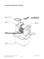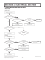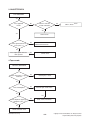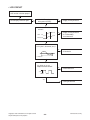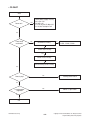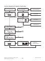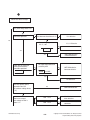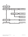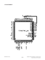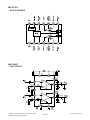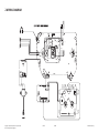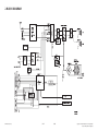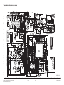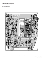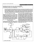
1
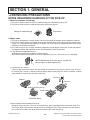
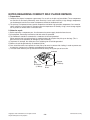
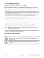
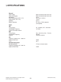
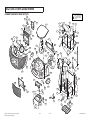
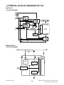
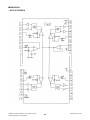
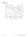
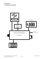
Internal Use Only
Website http://biz.lgservice.com
SERVICE MANUAL
MODEL : LPC-M155X , LPC12W
P/NO : AFN62795896
NOVEMBER, 2008
PORTABLE CD CASSETTE
RECORDER
SERVICE MANUAL
CAUTION
BEFORE SERVICING THE UNIT, READ THE “SAFETY PRECAUTIONS” IN THIS MANUAL.
MODEL : LPC-M155X , LPC12W
[CONTENTS]
❍ SECTION 1.GENERAL
• SERVICING PRECAUTIONS . . . . . . . . . . . . . . . . . . . . . . . . . . . . . . . . . . . . . . . . . . . . . 1-2
• ESD PRECAUTIONS . . . . . . . . . . . . . . . . . . . . . . . . . . . . . . . . . . . . . . . . . . . . . . . . . . . 1-4
• SPECIFICATION . . . . . . . . . . . . . . . . . . . . . . . . . . . . . . . . . . . . . . . . . . . . . . . . . . . . . . 1-5
❍ SECTION 2. EXPLODED VIEWS . . . . . . . . . . . . . . . . . . . . . . . . . . . . . . . . . . . . . 2-1
❍ SECTION 3.ELECTRICAL SECTION
• TROUBLESHOOTING GUIDE . . . . . . . . . . . . . . . . . . . . . . . . . . . . . . . . . . . . . . . . . . . . 3-1
• INTERAL BLOCK DIAGRAM OF ICs . . . . . . . . . . . . . . . . . . . . . . . . . . . . . . . . . . . . . . . 3-8
• WIRING DIAGRAM . . . . . . . . . . . . . . . . . . . . . . . . . . . . . . . . . . . . . . . . . . . . . . . . . . . 3-15
• BLOCK DIAGRAM . . . . . . . . . . . . . . . . . . . . . . . . . . . . . . . . . . . . . . . . . . . . . . . . . . . . 3-17
• SCHEMATIC DIAGRAMS . . . . . . . . . . . . . . . . . . . . . . . . . . . . . . . . . . . . . . . . . . . . . . 3-19
• PRINTED CIRCUIT BOARD DIAGRAM . . . . . . . . . . . . . . . . . . . . . . . . . . . . . . . . . . . . 3-21
❍ SECTION 4. REPLACEMENT PARTS . . . . . . . . . . . . . . . . . . . . . . . . . . . . . . . . . 4-1
Copyright © 2008 LG Electronics. Inc. All right reserved.
Only for training and service purposes
- 1-1 -
LGE Internal Use Only
SECTION 1. GENERAL
❏ SERVICING PRECAUTIONS
NOTES REGARDING HANDLING OF THE PICK-UP
1. Notes for transport and storage
1) The pick-up should always be left in its conductive bag until immediately prior to use.
2) The pick-up should never be subjected to external pressure or impact.
Storage in conductive bag
Drop impact
2. Repair notes
1) The pick-up incorporates a strong magnet, and so should never be brought close to magnetic materials.
2) The pick-up should always be handled correctly and carefully, taking care to avoid external pressure and
impact. If it is subjected to strong pressure or impact, the result may be an operational malfunction and/or
damage to the printed-circuit board.
3) Each and every pick-up is already individually adjusted to a high degree of precision, and for that reason
the adjustment point and installation screws should absolutely never be touched.
4) Laser beams may damage the eyes!
Absolutely never permit laser beams to enter the eyes!
Also NEVER switch ON the power to the laser output part (lens, etc.) of the pick-up if it is damaged.
NEVER look directly at the laser beam, and don’t let
contact fingers or other exposed skin.
5) Cleaning the lens surface
If there is dust on the lens surface, the dust should be cleaned away by using an air bush (such as used
for camera lens). The lens is held by a delicate spring. When cleaning the lens surface, therefore, a cotton
swab should be used, taking care not to distort this.
Pressure
Magnet
Pressure
How to hold the pick-up
Cotton swab
Conductive Sheet
6) Never attempt to disassemble the pick-up.
Spring by excess pressure. If the lens is extremely dirty, apply isopropyl alcohol to the cotton swab. (Do
not use any other liquid cleaners, because they will damage the lens.) Take care not to use too much of
this alcohol on the swab, and do not allow the alcohol to get inside the pick-up.
LGE Internal Use Only
- 1-2 -
Copyright © 2008 LG Electronics. Inc. All right reserved.
Only for training and service purposes
NOTES REGARDING COMPACT DISC PLAYER REPAIRS
1. Preparations
1) Compact disc players incorporate a great many ICs as well as the pick-up (laser diode). These components
are sensitive to, and easily affected by, static electricity. If such static electricity is high voltage, components
can be damaged, and for that reason components should be handled with care.
2) The pick-up is composed of many optical components and other high-precision components. Care must be
taken, therefore, to avoid repair or storage where the temperature of humidity is high, where strong magnetism is present, or where there is excessive dust.
2. Notes for repair
1) Before replacing a component part, first disconnect the power supply lead wire from the unit
2) All equipment, measuring instruments and tools must be grounded.
3) The workbench should be covered with a conductive sheet and grounded.
When removing the laser pick-up from its conductive bag, do not place the pick-up on the bag. (This is
because there is the possibility of damage by static electricity.)
4) To prevent AC leakage, the metal part of the soldering iron should be grounded.
5) Workers should be grounded by an armband (1M Ω)
6) Care should be taken not to permit the laser pick-up to come in contact with clothing, in order to prevent static electricity changes in the clothing to escape from the armband.
7) The laser beam from the pick-up should NEVER be directly facing the eyes or bare skin.
Armband
Resistor
(1 Mohm)
Resistor
(1 Mohm)
Copyright © 2008 LG Electronics. Inc. All right reserved.
Only for training and service purposes
Conductive
Sheet
- 1-3 -
LGE Internal Use Only
❏ ESD PRECAUTIONS
Electrostatically Sensitive Devices (ESD)
Some semiconductor (solid state) devices can be damaged easily by static electricity. Such components
commonly are called Electrostatically Sensitive Devices (ESD). Examples of typical ESD devices are integrated
circuits and some field-effect transistors and semiconductor chip components. The following techniques should
be used to help reduce the incidence of component damage caused by static electricity.
1. Immediately before handling any semiconductor component or semiconductor-equipped assembly, drain off
any electrostatic charge on your body by touching a known earth ground. Alternatively, obtain and wear a
commercially available discharging wrist strap device, which should be removed for potential shock reasons
prior to applying power to the unit under test.
2. After removing an electrical assembly equipped with ESD devices, place the assembly on a conductive surface such as aluminum foil, to prevent electrostatic charge buildup or exposure of the assembly.
3. Use only a grounded-tip soldering iron to solder or unsolder ESD devices.
4. Use only an anti-static solder removal device. Some solder removal devices not classified as "anti-static" can
generate electrical charges sufficient to damage ESD devices.
5. Do not use freon-propelled chemicals. These can generate electrical charges sufficient to damage ESD
devices.
6. Do not remove a replacement ESD device from its protective package until immediately before you are
ready to install it. (Most replacement ESD devices are packaged with leads electrically shorted together by
conductive foam, aluminum foil or comparable conductive materials).
7. Immediately before removing the protective material from the leads of a replacement ESD device, touch the
protective material to the chassis or circuit assembly into which the device will by installed.
CAUTION : BE SURE NO POWER IS APPLIED TO THE CHASSIS OR CIRCUIT, AND OBSERVE ALL
OTHER SAFETY PRECAUTIONS.
8. Minimize bodily motions when handing unpackaged replacement ESD devices. (Otherwise harmless motion
such as the brushing together of your clothes fabric or the lifting of your foot from a carpeted floor can generate static electricity sufficient to damage an ESD device).
CAUTION. GRAPHIC SYMBOLS
THE LIGHTNING FLASH WITH APROWHEAD SYMBOL. WITHIN AN EQUILATERAL TRIANGLE, IS
INTENDED TO ALERT THE SERVICE PERSONNEL TO THE PRESENCE OF UNINSULATED “DANGEROUS VOLTAGE” THAT MAY BE OF SUFFICIENT MAGNITUDE TO CONSTITUTE A RISK OF
ELECTRIC SHOCK.
THE EXCLAMATION POINT WITHIN AN EQUILATERAL TRIANGLE IS INTENDED TO ALERT THE
SERVICE PERSONNEL TO THE PRESENCE OF IMPORTANT SAFETY INFORMATION IN SERVICE
LITERATURE.
LGE Internal Use Only
- 1-4 -
Copyright © 2008 LG Electronics. Inc. All right reserved.
Only for training and service purposes
❏ SPECIFICATIONS
General
Power supply
Power consumption
Net Weight
External dimensions (W x H x D)
Output Power (T.H.D 10%)
Speakers
Battery Operation
Refer to the back panel of the unit.
Refer to the back panel of the unit.
2.3 kg
330 x 166 x 148 mm
1WX2
8 ΩX 2
DC 9V,six “C”(R14) batteries
(not supplied)
Tuner
FM
Tuning Range
Intermediate Frequency
Antenna Telescopic antenna
65 - 108 MHz, 87.5 - 108.0 MHz
10.7 MHz
AM
Tuning Range
Intermediate Frequency
Antenna
522 - 1620 kHz or 520 - 1720 kHz
455 kHz
Ferrite bar antenna
CD
Frequency response 100 - 18000 Hz
Signal-to-noise ratio
T.H.D
55 dB
0.5 %
Cassette tape player
Recording System
Frequency Response 125 - 8000 Hz
Signal to Noise Ratio
Copyright © 2008 LG Electronics. Inc. All right reserved.
Only for training and service purposes
4 Tracks 2 channel stereo
40 dB
- 1-5 -
LGE Internal Use Only
LGE Internal Use Only
- 1-6 -
Copyright © 2008 LG Electronics. Inc. All right reserved.
Only for training and service purposes
SECTION 2. EXPLODED VIEWS
• CABINET AND MAIN FRAME SECTION
296
NOTES) THE EXCLAMATION POINT WITHIN AN
EQUILATERAL TRIANGLE IS INTENDED
TO ALERT THE SERVICE PERSONNEL
TO THE PRESENCE OF IMPORTANT
SAFETY INFORMATION IN SERVICE
LITERATURE.
A49
450
450
294
293
295
458
459
297
292
301
298
453
250
DECK
453
300
278
291
269
290
CABLE1
299
A00
460
450
279
286
284
450
453
450
302
289
310
251
310
288
450
450
A46
252
278
453
285
MAIN
253
266
315
450
455
255
287
303
453
A40
450
456
450
268
256
457
275
258
POWER
257
280
A47
277
276
281
254
283
270
264
265
282
259
453
267
260
263
451
262
454
A26
450
274
260
260
261
305
454
452
450
273
267
452
272
304
271
454
Copyright © 2008 LG Electronics. Inc. All right reserved.
Only for training and service purposes
2-1
2-2
LGE Internal Use Only
LGE Internal Use Only
2-3
2-4
Copyright © 2008 LG Electronics. Inc. All right reserved.
Only for training and service purposes
• PACKING ACCESSORY SECTION
305 Power Cord
801 Instruction Ass'y
803 Packing
803 Packing
804 Bag
802 Box
Copyright © 2008 LG Electronics. Inc. All right reserved.
Only for training and service purposes
- 2-5 -
LGE Internal Use Only
LGE Internal Use Only
- 2-6 -
Copyright © 2008 LG Electronics. Inc. All right reserved.
Only for training and service purposes
SECTION 3. ELECTRICAL SECTION
❏ TROUBLESHOOTING GUIDE
• MAIN PART
1. AUDIO OUT
No power at IC701 pin1, 12
Yes
Is B+ applied to pn701?
No
Fuse open?
No
D901~904
normal?
No
Replace diode
Yes
Yes
Yes
Transformer check
Fuse change
No
Is Q703, 704 normal?
Yes
Replace
Q703, 704
SW 702 check
2. TUNER
Tuner Abnormal
Yes
Does 4.5V come out at
IC101 pin6?
No
Is B+ applied to
Q102?
No
Q901, ZD901 check
Yes
Yes
Q101, 102 check
Does signal come out at
pin13, 14?
No
IC101 check
Yes
SW 702 check
Copyright © 2008 LG Electronics. Inc. All right reserved.
Only for training and service purposes
- 3-1 -
LGE Internal Use Only
3. CASSETTE DECK
Deck ABNORMAL
Yes
Is B+ applied to
LEAF?
No
Does B+ come out
at Q901 collection?
No
CN701, ZD901 check
Yes
Yes
Does signal come out at
IC201 pin4, 11?
CN202 check
No
SW201 check
HEAD connector check
Yes
Does output signal come out
from speaker?
No
CN202 chec k
4. Tape recode
TAPE REC ABNORMAL
Yes
Does IC201 pin4, 11 signal
come out?
No
CN202 pin3, 4 check
Yes
No
Does L203 depart?
Does B+ light at leaf switch
Yes
Yes
Does departure signal go
into pn201, pin1, 3
No
R203, L204, L203 check
Yes
HEAD connector check
LGE Internal Use Only
- 3-2 -
Copyright © 2008 LG Electronics. Inc. All right reserved.
Only for training and service purposes
• LCD CIRCUIT
Is CD function selection proper?
Yes
Dose display LCD then light?
No
Check LCD supply power
in the power circuitry.
No
• Supply circuitry defective
Yes
Is IC1 reset circuit
normal?
3.3V
VDD
No
0V
3.3V
• Supply circuitry defective
• IC1 surrounding
circuit defective
Reset 0V
Yes
Is IC1 pin27, 28 normal (osc)?
No
• X1 defective
0.125usec
Yes
IC1 pin59, 60, 61, 62,
output wareform normal?
No
• Pattern defective
3.3V
Yes
• LCD light defective
Copyright © 2008 LG Electronics. Inc. All right reserved.
Only for training and service purposes
- 3-3 -
LGE Internal Use Only
• CD PART
Start
Yes
Power on?
No
Check power supply circuitry
IC4 1,4pin 7.2V
IC4 2pin 3.3V
IC1 12,16,25,50,64,73,98pin 3.3V
IC1 19,29,37,63,66pin 1.6V
Yes
Does initial
read work?
No
No
Check disc circuitry
Check connector
CON1, CON2, CON3
Yes
Check laser circuitry
Yes
Check Focus circuitry
Yes
Check tracking servo circuitry
Yes
Does it play?
No
Tracking servo check
Yes
Is audio output
supplied?
No
PN702 1, 4pin check
Yes
OK
LGE Internal Use Only
- 3-4 -
Copyright © 2008 LG Electronics. Inc. All right reserved.
Only for training and service purposes
IF INITIAL READING IS NOT CARRIED OUT (WITH DISC)
Does CON1 pin5 voltage change
when Limit S/W ON/OFF.
Does disc motor Rotate?
Yes
Is HF waveform output?
IC1 pin79
No
CON1 connector defective.
Yes
Is IC1 pin1 voltage transmitted?
No
No
2V
1V
IC1 Defective.
2V
Yes
Check the change of
SL +, SL - Voltage.
(IC2 pin 17, 18)
1.2V
No
0V
IC2 Defective.
0.8V
Yes
PICK-UP defective.
No
Does laser light?
A
Yes
Is FA+ waveform output at
IC2 pin3?
No
B
focus coil drive wareform.
Yes
Is TE waveform output at
IC1 pin96?
No
B
TRACKING ERROR wareform.
Yes
Is rotation normal?
Yes
Is HF signal normal without dropout?
Yes
IC1 defective.
PICK-UP defective.
No
Copyright © 2008 LG Electronics. Inc. All right reserved.
Only for training and service purposes
- 3-5 -
LGE Internal Use Only
When laser does not light
Is IC1 pin90 voltage about 2.5V?
No
Has pick-up returned to the
innermost position?
No
No
IC1 defective.
Are data transferrd form IC1?
Yes
Yes
Does voltage appear at
IC2 17, 18?
IC1, 2 Defective.
No
Yes
Slide motor defective.
Connector defective.
Yes
Does pick-up stop after
naving moved to the
innermost position?
Yes
Are input/output detected
at CON1 pin5?
OPEN
No
LMT SW defective.
Connector defective.
CLOSE
Yes
IC1 defective.
Has laser power source
returned to the Q5?
(Q5 collector voltage about
1.7V)
No
Connector defective .
Yes
Flow laser current?
Both voltage of R33 is
about 1.0?
LGE Internal Use Only
Yes
Q5 defective.
laser defective
Yes
Defective laser and/or
connector.
R33 »1.0V
R33 «1.0V
- 3-6 -
Copyright © 2008 LG Electronics. Inc. All right reserved.
Only for training and service purposes
B
Whe laser light
Yes
Does lenses move up and down?
No
Is signal output at focus
search ferminal?
No
IC1 defective.
Yes
Is signal output at CON3
pin13, 16(FC+, FC-).
No
IC2 defective.
Yes
Yes
• Autuator short
• Connecter short
No
• Connecter short
• IC1 defective.
No
• Laser diode degraded
• Pick-up defective
Is IC1 pin95 FEI signal output?
Yes
Is IC1 pin94 SBAD signal output?
Copyright © 2008 LG Electronics. Inc. All right reserved.
Only for training and service purposes
- 3-7 -
LGE Internal Use Only
❏ INTERAL BLOCK DIAGRAM OF ICs
■ AT24C32
• BLOCK DIAGRAM
■ KIA278R33P1
• BLOCK DIAGRAM
2 Vo
V IN 1
+
BANDG AP
REFERENCE
4
ASO
PROTECTION
OUTPUT ON/OFF
CONTROL
Control
OVER HEAT
PROTECTION
3
GND
LGE Internal Use Only
- 3-8 -
Copyright © 2008 LG Electronics. Inc. All right reserved.
Only for training and service purposes
■ MM1669AH
• BLOCK DIAGRAM
Copyright © 2008 LG Electronics. Inc. All right reserved.
Only for training and service purposes
- 3-9 -
LGE Internal Use Only
■ TA2111
• BLOCK DIAGRAM
LGE Internal Use Only
- 3-10 -
Copyright © 2008 LG Electronics. Inc. All right reserved.
Only for training and service purposes
■ TC94A77FG
• SYSTEM BLOCK DIAGRAM
Optical Pickup
LCD Display
RPT
MP3
ALBUM ALL
SYNC
WMA RANDOM PROG
4ch Driver
with MUTE
MM1469
CD processor, MP3/WMA decoder,
audio DAC and system controlling MCU
Analog
Audio Output
TC94A77FG-203
16.9MHz
Panel keys
Copyright © 2008 LG Electronics. Inc. All right reserved.
Only for training and service purposes
- 3-11 -
LGE Internal Use Only
• PIN ASSIGNMENT
LGE Internal Use Only
- 3-12 -
Copyright © 2008 LG Electronics. Inc. All right reserved.
Only for training and service purposes
■ UTC7312
• BLOCK DIAGRAM
■ UTC8227
• TEST CIRCUIT
Copyright © 2008 LG Electronics. Inc. All right reserved.
Only for training and service purposes
- 3-13 -
LGE Internal Use Only
LGE Internal Use Only
- 3-14 -
Copyright © 2008 LG Electronics. Inc. All right reserved.
Only for training and service purposes
❏ WIRING DIAGRAM
Copyright © 2008 LG Electronics. Inc. All right reserved.
Only for training and service purposes
3-15
3-16
LGE Internal Use Only
❏ BLOCK DIAGRAM
LGE Internal Use Only
3-17
3-18
Copyright © 2008 LG Electronics. Inc. All right reserved.
Only for training and service purposes
❏ SCHEMATIC DIAGRAMS
12
11
10
9
8
7
6
5
4
3
2
1
2007. 06. 12
A
B
C
Copyright © 2008 LG Electronics. Inc. All right reserved.
Only for training and service purposes
D
E
F
G
H
I
3-19
J
K
L
3-20
M
N
O
P
Q
R
S
T
LGE Internal Use Only
❏ PRINTED CIRCUIT DIAGRAM
MAIN P.C BOARD DIAGRAM
LGE Internal Use Only
3-21
3-22
Copyright © 2008 LG Electronics. Inc. All right reserved.
Only for training and service purposes