1
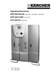
Service Handbook
Waterclean 600 CD,
LP/MP, PI
1.024-...
5.905-521
08.2004
FOREWORD
WTC 600 LP / MP
Foreword
Good servicing and maintenance requires comprehensive, practical training and clearly organised
documents.
This is why we offer all servicing engineers regular basic training and further qualification courses
for the whole product range.
In addition, we compile service manuals for the main units which can be used as instructions to start
with and as a reference work later on.
In addition, we issue regular Service Information about on-going developments of our products.
The texts and pictures can only be copied and duplicated or passed on to third parties after obtaining
explicit permission from:
ALFRED KÄRCHER GmbH & Co.
CUSTOMER SERVICE TRAINING
P. O. Box 160
D-71349 Winnenden
www.kaercher.com
2
Service Handbook 08.2004
WTC 600 LP / MP
CONTENTS
Contents
1
General.......................................................................................... 7 - 10
1.1
1.2
1.3
1.4
1.4.1
1.4.2
1.4.3
1.4.4
1.5
1.6
2
Description ................................................................................ 11 - 20
2.1
2.2
2.3
2.3.1
2.3.1.1
2.3.1.2
2.3.1.3
2.3.1.4
2.3.1.5
2.3.1.6
2.3.1.7
2.3.2
2.3.3
2.3.3.1
2.3.3.2
2.4
2.5
2.5.1
2.5.2
2.5.3
3
Introduction ........................................................................................................... 7
Marking of Instructions ........................................................................................ 7
Intended Use .......................................................................................................... 7
Safety Instructions ................................................................................................ 8
Quality of the Untreated Water ................................................................................. 8
Chlorination of Drinking Water .................................................................................. 8
Disposal of Chemicals ............................................................................................. 8
Handling Electricity / Protection Class ..................................................................... 9
General installation notes .................................................................................. 10
Units and Designations ....................................................................................... 11
Overview .............................................................................................................. 11
Flow Diagram ...................................................................................................... 13
Description of the System .................................................................................. 14
Modular Design ...................................................................................................... 14
Pre-chlorination Module ......................................................................................... 14
Flocculation Module ............................................................................................... 14
Mediafilter- and Activated Carbon Filter ................................................................ 15
RO System, Pump and Fine Filter ........................................................................ 15
Control Panel and Display ..................................................................................... 15
Anti Scalant and Post Chlorination ........................................................................ 15
Pressure-increase Pump ...................................................................................... 16
Safety Installations ................................................................................................. 16
Operating Modes .................................................................................................... 17
Automatic Operation (Standard Operating Mode) ................................................. 17
Manual Operation .................................................................................................. 17
Technical Data WTC 600 LP/MP ......................................................................... 18
Consumption Materials ...................................................................................... 20
Chemicals for Metering Container .......................................................................... 20
Cleaning Chemicals ............................................................................................... 20
Filter ....................................................................................................................... 20
Operation of the System .......................................................... 21 - 43
3.1
3.2
3.2.1
3.2.2
3.2.3
3.2.4
3.2.5
3.2.5.1
Assembly and Starting Operation ..................................................................... 21
Mixing Chlorine, Flocculation Agent and Antiscalant ..................................... 22
Initial Starting of Operation ..................................................................................... 22
Pre-chlorination ...................................................................................................... 22
Antiscalant .............................................................................................................. 24
Metering Amounts and Mixing of the Post Chlorination .......................................... 25
Flocculation Agent .................................................................................................. 25
Mixing of the flocking test solution .......................................................................... 25
Service Handbook 08.2004
3
CONTENTS
WTC 600 LP / MP
Contents
3.2.5.2
3.2.5.3
3.3
3.3.1
3.3.1.1
3.3.1.2
3.3.2
3.3.2.1
3.3.2.2
3.3.2.3
3.3.2.4
3.3.2.5
3.4
3.4.1
3.4.2
3.4.2.1
3.4.2.2
3.4.2.3
3.4.2.4
3.4.3
3.4.3.1
3.4.3.2
3.4.3.3
3.4.3.4
3.4.3.5
3.4.3.6
3.4.3.7
3.4.3.8
3.4.4
3.4.4.1
3.4.5
3.4.6
4
Maintenance .............................................................................. 44 - 62
4.1
4.2
4.3
4.3.1
4.4
4.4.1
4.4.2
4.4.3
4.4.3.1
4
Perform flocking test ............................................................................................... 26
Evaluate flocking test ............................................................................................. 26
Connecting the Equipment ................................................................................ 27
Connections, Valves and Indicators ....................................................................... 27
Pressure-increase Module .................................................................................... 28
RO Module with Preliminary Filters ....................................................................... 28
Electrical Connections ........................................................................................... 29
Pressure-increase Pump ...................................................................................... 29
Preliminary Filter ................................................................................................... 29
Metering Station .................................................................................................... 29
Float Switch ........................................................................................................... 31
Reverse Osmosis System .................................................................................... 31
Starting Operation ............................................................................................... 31
Metering Station ..................................................................................................... 31
Media filter and activated carbon filter .................................................................... 32
Initial Filling ............................................................................................................ 32
Starting Operation ................................................................................................. 32
Backwashing / Regeneration ................................................................................ 32
Programming ......................................................................................................... 33
Starting Operation of the RO System .................................................................... 35
Operating Levels and Passwords ......................................................................... 35
Menu Selection ...................................................................................................... 35
Selection of an Option ........................................................................................... 35
Selecting Several Arguments at the Same ............................................................ 36
Adjusting Operating Parameters and Balancing Values ......................................... 36
Acknowledging Data Inputs .................................................................................. 36
Operational Interruptions ....................................................................................... 36
Initial startup ........................................................................................................... 38
Normal Operation ................................................................................................... 40
Operating Messages for Normal Operation .......................................................... 41
Putting Out of Operation ......................................................................................... 42
Disinfection ............................................................................................................. 43
Fine Filter ............................................................................................................. 44
Metering Station WTC 600 CD ............................................................................ 44
Reverse Osmosis Module (RO Module) ............................................................ 45
RO Filter Replacement ........................................................................................... 45
Cleaning in Case of Malfunction ........................................................................ 46
Design of the Flushing and Disinfection Equipment ............................................... 47
Disinfection ............................................................................................................. 49
Acidic and Alkaline Cleaning .................................................................................. 50
Cleaning Solution for Acidic Cleaning ................................................................... 51
Service Handbook 08.2004
WTC 600 LP / MP
CONTENTS
Contents
4.4.3.2
4.4.4
4.4.4.1
4.4.4.2
4.4.4.3
4.4.5
4.4.6
4.4.7
4.5
4.5.1
4.5.2
4.5.3
4.5.4
4.6
4.6.1
4.6.2
Cleaning Solution for Alkaline Cleaning ................................................................. 51
Conserving ............................................................................................................. 51
Draining and rinse the metering stations ................................................................ 51
Conserve RO systems .......................................................................................... 51
Draining the pre-filter .............................................................................................. 53
Removing the Preservation After Longer Operational Interruptions ....................... 53
Rinsing the pre-filter ............................................................................................... 54
Replacing the activated carbon or filter sand ......................................................... 55
Malfunction, Cause and Corrective Action ....................................................... 57
Metering Station LED and Indicator LEDs at the Switch Cabinet ........................... 57
Malfunction Indication at the Operating Panel ........................................................ 58
Malfunctions of the RO Control and Metering Pump .............................................. 59
Malfunctions – Sand and Activated Carbon Filter, Fine Filter and Flocculation ...... 60
Maintenance Plan ................................................................................................ 61
Maintenance During Operation ............................................................................... 61
Maintenance Plan Service ..................................................................................... 62
Appendix ................................................................................... 63 - 84
RO control manufacture settings .......................................................................... 63
RO control program structure ............................................................................... 65
RO 1000: User manual ........................................................................................... 67
Operating Record for the WTC 600 LP/MP ........................................................... 84
List of key words ............................................................................. 86 - 88
Service Handbook 08.2004
5
WTC 600 LP / MP
6
Service Handbook 08.2004
WTC 600 LP / MP
1
General
1.1
Introduction
GENERAL
This service manual contains basic instructions and information which are to be observed upon
set-up, operation and maintenance.
Therefore, it is imperative that the service manual is read by the installer as well as by the
responsible specialist staff prior to installation and starting of operation. Please observe not only
the general safety instructions listed in the section “Safety Instructions”, but also the special
safety instructions included in the other sections.
1.2
Marking of Instructions
The safety instructions contained in these operating instructions, which in case of
non-observance can cause dangerous situations for persons, are specially marked
with the general symbol for dange.
The safety instructions contained in these operating instructions, which in case of
non-observance can cause poisoning, cauterizing, etc. for persons, are specially
marked with the death’s-head symbol.
CAUTION Following this symbol are recommendations or tips which make working easier and
provide for secure operation.
NOTE
Following this symbol are recommendations or tips which make working easier and
provide for secure operation.
Instructions that are attached directly to the equipment must be observed under all means and
kept in completely readable condition.
1.3
Intended Use
The equipment is intended for the conditioning of untreated water into drinking water.
The retention degree of harmful chemical substances and biological pathogens or contaminants
is very high.
The quality of the produced drinking water ultimately depends on the contamination degree and
salt content of the untreated water.
- Prior to the initial starting of operation, we recommend carrying out an analysis of the
untreated water.
- Continuous drinking-water quality can be ensured only when the equipment is controlled
regularly.
- The respective national or international drinking water regulations are to be observed.
Under consideration of these rules of conduct, water produced from this system can quite safely
be classified as drinking water.
Service Handbook 08.2004
7
GENERAL
WTC 600 LP / MP
1.4
Safety Instructionse
1.4.1
Quality of the Untreated Water
Sufficient quality of the untreated water must be ensured!
Faultless drinking water is achieved only when all filters of the equipment are
maintained regularly.
1.4.2
Chlorination of Drinking Water
When applying post chlorination, the limit values set by national laws must be maintained. The chemicals used have a caustic and fire-promoting effect.
Dangers:
- Danger of fire in case of contact with combustible materials.
- Toxic gas develops when coming in contact with acids.
- Heat or direct sunlight decomposes the chemical: Chlorine and oxygen are released.
- Caustic effects to the eyes, skin and respiratory system result.
Safety Instructions:
- Wear acid-resistant protective equipment (goggles, gloves) and when dust is produced,
breathing mask protection with a filter.
- Keep an eye wash bottle (small) readily available.
- Provide for adequate room ventilation and a washing facility.
- Store the chemicals in a cool, dry place, not below 5 °C.
- Store chemicals in a location out of the reach of children.
In Case of Accidents:
- In case of contact with the eyes, rinse immediately and thoroughly with fresh water and
consult a doctor.
- Use water to extinguish; avoid impact and friction.
- If solutions are spilt, flush the area with a sufficient amount of fresh water.
1.4.3
Disposal of Chemicals
It is generally recommended to admit resulting disinfection solutions, preservation solutions, etc.
into a neutralizing system.
If this should not be possible, the disinfection solution, after clarification with the relevant
authority (mayor’s office, district administration office, etc.) is to be neutralized and can
afterwards be led into the public sewer system.
8
Service Handbook 08.2004
WTC 600 LP / MP
1.4.4
GENERAL
Handling Electricity / Protection Class
Be aware of dangerous electrical voltage!
For work on components/assemblies which are marked with this symbol, protective
measures are to be taken:
- Switch off the power
- Secure against restarting
- Check and assess that no voltage is given.
The electrical connection of the equipment may be carried out only by a qualified
electrician.
The power supply cable must be fitted with a protective conductor
(protection class I).
1.5
General installation notes
- Only use food safe components and resources on the drinking water side
- Pay special attention to hygienic cleanliness when installing drinking water pipes.
1.6
Units and Designations
Unit
Designation
bar
bar (pressure)
di/da
Diameter, inside / diameter, outside
g/h
Gram per hour
Hz
Hz (frequency)
l
Liter
l/h
Liter per hou
mg/h
Milligram per hour
mg/l
Milligram per lite
ml
Milliliter
V AC
Volt (AC)
W
Watt (power)
°dH
Degree of hardness (water hardness)
µS/cm
Microsiemens per cm (spec. conductance value
ETL
Spare parts list
LW
Conductance value
SLP
Circuit Diagram
Table 1
Units and their meaning
NOTE
1000 milliliter = 1 liter; 1000 mg = 1
Service Handbook 08.2004
9
DESCRIPTION
WTC 600 LP / MP
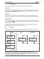
2
Description
2.1
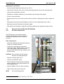
Overview
1.2
2.1
4.12, 4.13
f
g
4.23
c
e
b
d
4.24
a
4.21
4.14
4.11
4.15
4.17
4.4
4.3
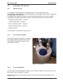
2.2
4.7
1.3
Figure 1
10
4.5, 4.6
Overview of components
Service Handbook 08.2004
WTC 600 LP / MP
DESCRIPTION
Legend for figure 1 and figure 2:
1.1 Pre-chlorination metering point
4.11 Manometer, pump pressure
1.2 Manometer - media filter inlet pressure
4.12 Membrane pressure pipe
1.3 Media filter
4.13 Membrane
1.4 Differential pressure switch
4.14 Manometer - concentrate pressure
1.5 Concussion restrictor
4.15 Concentrate control valve
1.6 Flocculation metering point
4.16 Concentrate flowmeter
2.1 Manometer - activated carbon filter
inlet pressure
4.17 Pressure control valve
2.2 Activated carbon filter
4.18 High-pressure pump
4.1 Antiscalant metering point
4.19 Conductivity and temperature
measuring cell - drinking water
4.2 Non-return valve
4.20 Drinking water flowmeter
4.3 Untreated water sampling tap
4.21 Drinking water sampling tap
4.4 Manometer - fine filter input pressure
4.22 Non-return valve
4.5 Fine filter housing
4.23 Post chlorination metering point
4.6 Fine filter candle
4.24 Reverse osmosis control
4.7 Manometer - fine filter output pressure
6.1 Pre-chlorination metering
4.8 Input solenoid valve
6.2 Antiscalant metering
4.9 Manostat
6.3 Post chlorination metering
4.10 High-pressure pump
6.4 Flocculation metering
Items 1.1 to 6.4 are attached to the components as reference numbers.
a
Media filter control
b
Control, activated carbon filter
c
Control cabinet
d
Manual / automatic rotary switch
e
Master switch
f
Media and activated charcoal
plug sockets
g
Power outlets (3x) for metering
stations
Service Handbook 08.2004
11
DESCRIPTION
WTC 600 LP / MP
2.2
Flow Diagram
Figure 2
Flow diagram of the complete reverse osmosis system (RO system)
12
Service Handbook 08.2004
WTC 600 LP / MP
2.3
Description of the System
2.3.1
Modular Design
DESCRIPTION
The installation is a drinking water conditioning system. Its core application is the
emineralization of brackish water with a salt content up to 2000 ppm (WTC 600 LP), respectively
up to 5000 ppm (WTC 600 MP).
The design of the system is modular, and can be adapted accordingly to the local conditions
depending on the application conditions as well as the composition of the untreated water:
- Media filter and flocculation – module 1
- Activated carbon filter – module 2
- Reverse osmosis system – module 4
- Pressure-increase pump – module 5
- Metering stations
The RO system is designed for stationary use.
2.3.1.1
Pre-chlorination Module
The WTC 600 CD metering station, consisting
of metering container (3/1) and pump (3/2), is
connected to the sand filter module for prechlorination if required.
2
1
Figure 3
2.3.1.2
WTC 600 CD
Flocculation Module
The WTC 600 CD metering station (see figure 3) with injection adapter is connected to the sand
filter module for pre-flocculation if required.
The exact requirement of flocculation agent is to be determined when starting operation (see
Section 3.2.5).
Service Handbook 08.2004
13
DESCRIPTION
2.3.1.3
WTC 600 LP / MP
Mediafilter- and Activated Carbon Filter
The pre-filter units of the RO system consist of the media filter and the activated carbon filter.
The filter fillings consist of support pebbles and filter sand according to DIN 19623, as well as
activated carbon.
The filters are each controlled by means of a central control valve with microprocessor control
and located at the top of the filter.
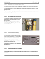
2.3.1.4
RO System, Pump and Fine Filter
The fine filter is located on the front side of the
equipment. It is connected directly in front of
the RO system.
1
The RO pump (4/2) pumps the pre-filtered
water through two RO filters (4/1) which are
connected in series.
2
Figure 4
2.3.1.5
RO pump
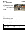
Control Panel and Display
The control panel is used for data input in the
control and as LED indicator for the operating
modes and malfunction indications (5/1).
2
Parameters are entered with the arrow
pushbuttons. Data input is acknowledged with
the ENTER pushbutton (5/4) and cancelled
with the ESC pushbutton (5/3).
1
Programming conditions, etc., are indicated in
the display (5/2).
Figure 5
2.3.1.6
3
4
Control panel and display
Anti Scalant and Post Chlorination
For hardness stabilization of the untreated water and post chlorination of the drinking water a
WTC 600 CD metering station is connected to the RO module in the same manner as for prechlorination.
14
Service Handbook 08.2004
WTC 600 LP / MP
2.3.1.7
DESCRIPTION
Pressure-increase Pump
If required, the WTC 600 PI pressure-increase
pump (6/1) is connected between untreated
water supply and RO system. It is used for
pressure increase of the untreated water.
NOTE
1
A pressure-increase pump should
be used for a water pressure (flow
pressure) ⱕ 2 bar.
CAUTION Observe mechanical protection as
well as protection of the
connection cable against water!
Figure 6
2.3.2
WTC 600 PI
Safety Installations
Emergency Stop
The emergency stop switch (7/4) (main switch) is located on the side of the switch box.
RC Protective Switch
RC protective switch (external): i ⱕ 30 mA
Circuit Breaker
Automatic circuit breaker (7/3) 10 A for power limitation of the power outlets, etc
Motor Protection Switch
The motor protection switch (7/2) is factory-set depending on the power consumption of the RO
pump (compare circuit diagram (7/1)) and must be checked:
WTC 600
Nominal output
RO pump
Actual power
consumption
Motor protection
switch setting
LP 400 V
2.2 kW
1.5 kW
4A
MP 400 V
2.2 kW
2.2 kW
5.1 A
LP 230V
2.2 kW
1.5 kW
10 A
MP 230 V
2.2 kW
2.2 kW
14 A
Table 2
Setting of motor protection switch
Service Handbook 08.2004
15
DESCRIPTION
WTC 600 LP / MP
Microfuses
Two microfuses (7/6) for protection of the
control electronics (7/5) are located on the
control board for the electronics:
3
2
5
4
1
- 5x20 6,3 A time-delay
6
- 5x20 0,1 A time-delay.
Figure 7
Switch cabinet and control electronic
2.3.3
Operating Modes
2.3.3.1
Automatic Operation (Standard Operating Mode)
After switching on the main switch, the system is fully automatic controlled through the
electronic control system and the float switch in the drinking water tank. The mode selector
switch is in the “Auto” position.
The control system usually operates in the normal plane in the operating mode operation.
With the exception of an error acknowledgement (only in case of pre-selection Vwacknowledgement by actuating the ESC key button), no further operating by the operator is
possible; this is to protect the control system against unintended / unauthorized manipulations.
NOTE
By entering the respective password, the user level or the technician level for input
of operating parameters, etc. is cleared (see section 3.4.3.1). The program structure
is given in the appendix, Figure 21.
NOTE
Operating parameters and setting values are listed on the data sheet by the
manufacturer (cf. Tables 34 and 35).
2.3.3.2
Manual Operation
The float switch in the drinking water tank is deactivated by the manual / automatic rotary switch
("Manual" position), so that the plant can run continuously.
CAUTION Manual operation is not standard operating mode, as the system does not switch off
automatically.
16
Service Handbook 08.2004
WTC 600 LP / MP
2.4
DESCRIPTION
Technical Data WTC 600 LP/MP
Parameter
WTC 600 LP
WTC 600 MP
Ambient temperature
+1°C - +50°C
Storage temperature (delivery)
to -10°C
Humidity
<100% r.F.
Supply voltage
3*400V 50 Hz1)
1*230V 50 Hz1)
Pre-filter controls: prim / sec.
230 V/12 V 50 Hz
Metering pumps
230 V 50-60Hz
Wiring
3 Ph, N, PE
Electrical protection
16 A
Connected electrical load
2.2 kW
2.2 kW
Effective electrical power consumption
1.5 kW
2.2 kW
Mechanical protection / protection against water
Switch cabinet
IP44
Pump and valves
IP44
Metering pump
IP44
Power outlets (plug inserted)
< IP44
Minimum temperature of untreated water
+5°C
Maximum temperature of untreated wate
+35°C
Reference temperature
+15°C
pH-value, untreated water
6-9.5
pH-value during cleaning
3-11
System input pressure and flow
2-6 bar at min. 2 m³/h
Capacity range
15000 l/day (±10%)
Maximum drinking water capacity
650 l/h
Dimensions: H x W x D
WTC 600 LP/MP
1800 x 660 x 720 mm
WTC 600 LP/MP - A
1800 x 1120 x 720 mm
WTC 600 LP/MP - AM
1800 x 1120 x 720 mm
Weight in delivery condition (without filter container)
WTC 600 LP/MP
135 kg
WTC 600 LP/MP - A
155 kg
WTC 600 LP/MP - AM
175 kg
Table 3
1)
Technical Data
depending on the system version
Service Handbook 08.2004
17
DESCRIPTION
WTC 600 LP / MP
Filter Container
Volume per container
103 l
Filling capacities, Mediafilter
Support pebbles 2.0 - 3.15 mm
15 kg
Filter sand 0.4 - 0.8 mm
100 kg
Filter amounts, activated carbon filter
Support pebbles 1 - 2 mm
15 kg
Activated carbon filter F100
32 kg
Water connections
Inlet threaded connection hose nozzle
Outer diameter d25
Drinking water threaded connection hose nozzle
Outer diameter d25
Concentrate threaded connection hose nozzle
Outer diameter d25
Outlet for flushing water
HT pipe d50
Canal connection (supplied by customer)
> DN 50
Hydraulic Data
Maximum allowable flow rate in filteroperation
1,3 m3/h
Amount of waste water produced during
backwashing
2 m³/h, ca. 670 liter per backwashing
Allowable Operating Conditions
Maximum pressure
6 bar
Metering Pump
Feed capacity at max. counter-pressure (10 bar)
1 l/h
Metering Container:
Weight with pump
10 kg
Connections
Hose connections (PE) di/do
4/6
Hose connection, ventilation (PVC) di/do
4/6
Float Switch
Minimum hysteresis
Table 4
18
300 l
Technical Data
Service Handbook 08.2004
WTC 600 LP / MP
2.5
DESCRIPTION
Consumption Materials
Swear protective equipment and observe safety instructions!
2.5.1
Chemicals for Metering Container
For mixing of the metering solution, use the measuring cup with the handle (250 ml or 1000 ml).
NOTE
Explanations of the units, see Chapter 1.6.
NOTE
A metering container from the WTC 600 CD metering station has a volume of 75 liter.
Product
ItemNo.
Chlorinated lime
6.291-505.0
Sterilization agen RM 852
6.291-772.0
RM 5000 hardness stabilization
6.290-991.0
RM 5001 Flockulents, 10 l
6.294-703.0
RM 5001 Flockulents, 60 l
6.294-716.0
Table 5
Kärcher Original Products
2.5.2
Cleaning Chemicals
Product
Item No.
RM Kleen MCT 511
6.294-008.0
RM Kleen MCT 103
6.294-009.0
RM P3 Oxonia Active
6.294-010.0
RM 1,2 Propandiol, 5 l
6.290-910.0
Sulfite 5 kg
6.769-040.0
Soda
6.287-014.0
RM 511 Vaporapid bio-descaling acid
6.290-239.0*
Table 6
Cleaning Chemicals
2.5.3
Filter
* Attention! Note national variants!
Product
Item No.
Filter element 5µ
6.414-466.0
Replacement set, metering pump
6.762-172.0
Table 7
Filter Elements
Service Handbook 08.2004
19
OPERATION OF THE SYSTEM
3
Operation of the System
3.1
Assembly and Starting Operation
WTC 600 LP / MP
Assembly
Chapter
Checking the scope of delivery (delivery note)
Placing the equipment in the set-up location and positioning
Connecting the untreated water to the WTC 600 LP/MP; connecting
the WTC 600 PI in between, if required (depending on delivery scope)
2.2, 3.3.2.1, 3.3.1
Installing the piping for backwashing and drinking water
2.2
Installing the float switch
3.3.2.4
Filling and connecting the sand filter and the activated carbon filter
3.4.2
Connecting the electrical system
SLP, 3.3.2
Table 8
Assembly work to be carried out upon starting operation
Starting Operation
Chapter
Establishing the untreated water supply
2.2
Manually actuating the sand filter backwashing
3.4.2
Manually actuating the activated carbon filter backwashing
3.4.2
Flushing the reverse osmosis
3.4.3.7
Filling the chemicals container
3.2
Adjusting the flow rates
3.4.3.8
Filling out the metering table in the operating instructions
Instructing the operator (operating instructions)
Table 9
Overview of start-up work
A water analysis with the following values must exist for commissioning of the WTC 600:
- Total hardness GH in °dH
- Iron Fe in mg/l
- Manganese Mn in mg/l
- Ammonium NH4 or NH3 in mg/l
- System yield determined by the sales department (Normal case: 75%, in special cases 50%).
20
Service Handbook 08.2004
WTC 600 LP / MP
OPERATION OF THE SYSTEM
3.2
Mixing Chlorine, Flocculation Agent and Antiscalant
3.2.1
First fill of the metering tanks
The first time they are filled, the metering tanks are filled with 30 litres of chlorine-free water.
This is taking from the reverse osmosis at the drinking water sampling tap (1/12).
For the first fill of the metering tank, the system is switched to disinfection mode and set to the
following flow rates:
- Drinking water: 100 l/h
- Concentrate: 600 l/h
CAUTION During the disinfection operating mode, all confirmation queries are switched off!
Observe the pressure downstream of the fine filer: as soon as it is less than 2 bar
pressure, immediately switch off the system. The high-pressure pump is running dry!
Use the prescribed system yield (50% or 75%) and the water analysis to determine each of the
chemical quantities for a 30 litre metering solution according to Chap. 3.2 to 3.5, add to the tanks
and mix well.
Switch the system to operation mode.
3.2.2 Pre-chlorination
CAUTION Only use drinking water to dilute the original chlorine product upstream of the
chlorination point. This water is taken from the drinking water tap (1/4.21).
1. Take the system yield (50% or 75%) from the evaluation of the untreated water analysis.
2. Take the analysis values for iron (Fe), manganese (Mn) and ammonium (NH3 or NH4 ) in mg/l
from the untreated water analysis.
3. Iron content:
____ x 0,4 = ______
Manganese content:
____ x 0,6 = ______
Ammonium content:
____ x 8,0 = ______
Basic requirement:
Total:
1,2
==========
4. For 50% yield:
Total x 192 = ____ ml RM 852 per 10 litre metering solution
OR
Total x 512 = ____ ml calcium hypochlorite (1ml corresponds to 1.05g) per 10 litres metering solution
Service Handbook 08.2004
21
OPERATION OF THE SYSTEM
WTC 600 LP / MP
5. For 75% yield:
Total x 128 = _____ ml RM 852 per 10 litre metering solution
OR
Total x 348 = _____ ml calcium hypochlorite (1ml corresponds to 1.05g) per 10 litres metering solution
These values are entered in the customer's operating instructions.
Calculation example:
- Yield 75%
- Iron (Fe) 1.0 mg/l
- Manganese (Mn) 1.0 mg/l
- Ammonium (NH4) 0.2 mg/l
Iron content:
1,0 x
0,4 =
0,4
Manganese content:
1,0 x
0,6 =
0,6
Ammonium content:
0,2 x
8,0 =
1,6
Basic requirement:
1,2
Total:
3,8
For 75% yield:
Total x 128 = 486 ml RM 852 per 10 litre metering solution
OR
Total x 348 = 129 ml calcium hypochlorite (1ml corresponds to 1.05g) per 10 litres metering solution
22
Service Handbook 08.2004
WTC 600 LP / MP
3.2.3
OPERATION OF THE SYSTEM
Antiscalant
The drinking water for the metering solution is taken from the sampling tap for drinking
water (1/4.21).
The antiscalant metering quantity can be set with a very good approximation using the following
table. The optimum quantity can only be calculated using a calculation program after a precise
water analysis has been carried out. The typical metering range lies between 2 and 5 mg/l.
Where water hardnesses are higher than 28°dH, special design is necessary.
If this design is not possible, the following setting is recommended: 5 mg/l RM5000 and 50%
yield, until the precise design is available.
Range of Water Hardness
Antiscalant [mg/l]
Metered
amount of
RM 5000 [ml]
per 10 l
Metering
Solution
Run-down
Tank Service
Life [h]
1 (0°-7° dH)
2,5
58
214
2 (7°-14° dH)
3
69
214
3 (14°-21° dH)
4
92
214
4 (21°-28° dH)
5
115
214
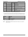
Table 10
Metering of antiscalant at 75% yield
Range of Water Hardness
Antiscalant [mg/l]
Metered
amount of
RM 5000 [ml]
per 10 l
Metering
Solution
Run-down
Tank Service
Life [h]
1 (0°-7° dH)
2,5
87
214
2 (7°-14° dH)
3
104
214
3 (14°-21° dH)
4
138
214
4 (21°-28° dH)
5
173
214
Table 11
Metering of antiscalant at 50% yield
1 °dH = 1,79 °frH
1 °dH = 17,9 mg CaCO3/l
1 °frH = 10,0 mg CaCO3/l
Service Handbook 08.2004
23
OPERATION OF THE SYSTEM
3.2.4
WTC 600 LP / MP
Metering Amounts and Mixing of the Post Chlorination
The chlorine quantity given matches a chlorine content of 0.3mg/l in the drinking water.
The following quantities of RM 852 or calcium hypochlorite are each required for 10 litres of
metering solution:
- RM 852 Sterilization Agent:
32 ml
- Chlorinated Lime:
17 ml (= 18 g)
Example: 75 litres ready mixed metering solution (one metering tank) consists of 7.5 x 32 = 240 ml
RM 852 or 7.5 x 17 = 128ml (=136 g) calcium hypochlorite and chlorine-free drinking water
(cf. Chapter 3.2.3 for extraction).
The quantities must be adjusted accordingly for higher or lower chlorine contents.
Example: Chlorine content: 1.2 mg/l
- RM 852:
4 x 32 ml = 128 ml
- Chlorinated Lime:
4 x 17 = 68 ml
3.2.5
Flocculation Agent
The exact demand in flocculents can only be determined by test. Therefore a test solution is
mixed first, then the raw water is flocked and finally the dosing quantity is evaluated.
3.2.5.1
Mixing of the flocking test solution
Auxiliaries:
- Measuring cup with 500-ml-scale 6.277-001.0 (within service kit)
- Desalinated water (refill water for car batteries)
- Flocculent RM 5001 6.294-716.0 resp. 6.294-703
- Measuring cup 25 ml 6.394-425.0 (within service kit)
- Dropping bottle 50 ml,PE 6.394-426.0 (within service kit)
- Plastic eating spoon.
Work Steps:
1. Give 25 ml flocculent RM 5001 into measuring cup
2. Fill up with desalinated water to 500 ml
3. Stir up thoroughly with plastic eating spoon
4. Give 50 ml of this into a clean dropping bottle, close bottle
5. Cast away the remainder.
24
Service Handbook 08.2004
WTC 600 LP / MP
3.2.5.2
OPERATION OF THE SYSTEM
Perform flocking test
Auxiliaries:
- Transparent cup, 1 litre with marking at 0.5 litre 6.277-001.0
- Dropping bottle with test solution 6.394-426.0
- Plastic eating spoon.
Work Steps:
1. Measure pH-value of water, has to be between 6 and 9
2. Pour 0.5 Liter raw water into cup
3. Give 10 drops of flocking test solution into spoon
4. Fill flocking test solution into cup, at this stir strongly for 5 seconds
5. Leave cup: flocking has to start within 1 minute and settle significantly.
NOTE
If no flockung has start repeat test and change quantity of flocking test solution (first
more test solution, if not successful repeat with less test solution).
If analysis is not possible on the spot, take out 2 litres of test solution and store in refrigerator at
ca. 4°C until analysis. Cooling maintains cloudiness by suspended matter.
NOTE
Shake well before measurement in laboratory.
3.2.5.3
Evaluate flocking test
Adjustment of dosing pump flocking means:
- Stroke: 40%
- Frequency: 70%.
The required amount of flocculation agent RM 5001 is then calculated as follows:
- For 50% yield: number of drops x 120 = ml RM 5001 per 10 litres metering solution
- For 75% yield: number of drops x 80 = ml RM 5001 per 10 litres metering solution
Calculation example:
The flocculation test gave 11 drops of flocculation test solution to 500ml up to ideal flocculation,
the yield is 75%:
11 drops x 80 = 880 ml RM 5001 per 10 litres of metering solution
Service Handbook 08.2004
25
OPERATION OF THE SYSTEM
3.3
Connecting the Equipment
3.3.1
Connections, Valves and Indicators
WTC 600 LP / MP
Depending on the local untreated water supply, the WTC 600 LP/MP is connected directly to the
off-site supply or supplemented through a WTC 600 PI pressure-increase module.
The following constructional measures must be observed:
- The off-site untreated water supply must be equipped with a shut-off device (supplied by user
/ customer).
- All pipes / lines (untreated water, backwashing, concentrate and drinking water) to be installed
without mechanical tension.
- Drinking water line to be installed with free run-out and no further shut-off devices.
- Backwashing line to be installed with steady drop (under no circumstances inclined upward).
For easy and secure operation and maintenance of the system, minimum clearances
from the walls are to be observed:
Page
Minimum clearances [cm]
A
50
B
10
C
70
D
50
Table 12
Minimum clearances
Figure 8
Minimum clearances WTC 600 LP/MP
2
3
1
Figure 9
Water connections, WTC 600 PI
Installation space (incl. working space for maintenance and operation, not including piping):
WTC 600 LP and MP: width x depth: 1300 x 1900mm
WTC 600 LP-A, LP-AM, MP-A, MP-AM: width x depth: 1700 x 1900 mm
WTC 600 CD: width x depth: 500 x 1100 mm
WTC 600 PI: width x depth: 600 x 200 mm
26
Service Handbook 08.2004
WTC 600 LP / MP
3.3.1.1
OPERATION OF THE SYSTEM
Pressure-increase Module
Connection to the RO system (9/2) Hose shank d25
Connection to the untreated water (9/3) Hose shank d25
CAUTION Observe mechanical protection of the electrical connection cable (9/1) as well
as protection against water!
The fan wheel of the pump must be at least 20 cm away from the next wall.
CAUTION Otherwise damage to the motor caused by heat build-up must be considered.
3.3.1.2
RO Module with Preliminary
Filters
2
In the delivery condition, blind discs are
installed for means of preservation to the
screwed connection above the Antiscalant
(10/1) metering line as well as to the drinking
water connection (11/4) and to the concentrate
connection (11/3). These are to be removed
before starting operation.
Metering line connection for pre-chlorination
(10/2)
Untreated water connection (10/3) hose shank
d25
3
1
4
Figure 10 Connections, rear
Concentrate drain (10/4) HT-pipe d50
3
Drinking water connection (11/4) hose shank
d25
Metering line connection for post chlorination
(11/5)
Sampling valve for drinking water (11/6)
4
5
2
6
7
1
8
Sampling valve for untreated water (11/9)
Pressure control valve (11/1)
Flow meter, concentrate (11/2)
9
Flow meter, drinking water (11/7)
Figure 11 Connections, front
Concentrate control valve (11/8)
Service Handbook 08.2004
27
OPERATION OF THE SYSTEM
3.3.2
Electrical Connections
3.3.2.1
Pressure-increase Pump
WTC 600 LP / MP
230 V external, via connection cable.
3.3.2.2
Preliminary Filter
In delivery condition, the preliminary filters are connected to the power outlets (1/f) on the rear
side of the RO equipment.
3.3.2.3
Metering Station
The pumps of the projected metering stations are connected to the power outlets (1/g).
NOTE
The cable from the float switch must be inserted in the metering pump unit.
Digital input
(release)
2
1
Alarm output
(empty alarm)
Figure 12 Alarm output and digital input of the metering pumps
For connection of the control cables in the
electrical switching cabinet, the blind
connections in the flange plate (13/4) are
replaced by the enclosed cable screw fittings
(13/3).
Connect the control cables in accordance with
Table 13.
NOTE
NOTE
28
The complete connecting
diagrams / plans (13/1) are located
in the switch cabinet.
The connections for signal inputs
that are not required are bridged at
the connecting terminal (13/2).
1
2
3
4
Figure 13 Connections, metering stations
Service Handbook 08.2004
WTC 600 LP / MP
Metering
OPERATION OF THE SYSTEM
Type
Function
Signal Line
Container
Pre-chlorination
Terminal,
El. Cabinet
Alarm output (12/1
not required
Empty signal
Digital input (12/2)
Release
not required
Antiscalant
Alarm output (12/1)
not required
Empty signal
Digital input (12/2)
Release
not required
Post chlorination Alarm output (12/1)
not required
Empty signal
Digital input (12/2)
Release
not required
Table 13
Connecting
white
-----
blue
-----
brown
14
black
15
brown
8
blue
9
white
-----
black
-----
white
-----
blue
-----
brown
16
black
17
brown
10
blue
11
white
-----
black
-----
white
-----
blue
-----
brown
18
black
19
brown
12
blue
13
white
-----
black
-----
Connection assignment: Empty message and releasing of the metering containers at
the RO control
CAUTION Electrically insulate cable ends that are not used with insulating terminals.
Service Handbook 08.2004
29
OPERATION OF THE SYSTEM
3.3.2.4
WTC 600 LP / MP
Float Switch
Connect the signal lines of the enclosed float switch to clamps 6/7 (8S3 option) of the
connecting terminal – compare wiring diagram in the switching box. Upon installation, adjust a
switching hysteresis of at least 300 liters between the switching-on and switching-off point.
3.3.2.5
Reverse Osmosis System
The WTC 600 LP/MP is connected to the following power supply:
- 400 V / 50Hz, 3Ph + N + PE or 230 V / 50Hz, 1Ph + N + PE (depending on type of system)
- Fuse protection 16 A
- RC protective switch 30 mA from source of power supply (check if in existence or have
confirmed in writing).
3.4
Starting Operation
Operation of the individual equipment components is started in the following sequence:
- Fill the preliminary filter and start operation by backwashing (3.4.2)
- De-conserve reverse osmosis (3.4.3.7)
- Fill metering container and start operation (3.4.1)
- Start the operation of the reverse osmosis (3.4.3.8)
3.4.1
Metering Station
NOTE
Pushbutton for venting in “continuous operation” (14/3).
Operating mode on “Manual” (14/2)!
Change the operating mode by pressing the
"Mode" key (14/2).
3
4
Modul
Lift
(14/1)
Frequency Meter(14/4)
ing
Prechlorination
40%
70%
3.2.2
Antiscalant
40%
50%
3.2.3
Post
clorination
40%
70%
3.2.4
Flocculation
40%
70%
3.2.5
Table 14
NOTE
30
1
2
Checking pump settings
Figure 14 Metering station
Adjust the lift only when the
pump is running. Danger of
damaging!
Service Handbook 08.2004
WTC 600 LP / MP
OPERATION OF THE SYSTEM
3.4.2
Media and Activated Carbon Filter
3.4.2.1
Initial Filling
Remove the central control valve and position the central pipes with the lower nozzle in the
middle of the tank floor. Fill the tank up to a third with water. Place the filling funnel (4.901-090.0)
in the opening and fill the filter bed with a shovel (6.812-049.0) in accordance with Table 15:
Filter
Support pebbles
Filter sand / Activated carbon
Media filter
15 kg
Grain size 2,0-3,15 mm
100 kg
Grain size 0,4-0,8 mm
Grain size 1-2 mm
32 kg
Actvated carbon grain F100
Activated carbon 15 kg
Table 15
Completely fill the tank with water
Align the central pipe in the middle of the container opening and reinsert the central control valve
again after removing the cover. Connect the hydraulic connections again.
3.4.2.2
Starting Operation
After filling, the filters must be backwashed. For this the complete system is to be connected
hydraulically and electrically, and to be switched on at the main switch. The reverse osmosis
system must be in the Switched Off operating mode (compare 3.4.3 – 3.4.5). The
backwashing is initiated manually with the MANUAL REGEN pushbutton (15/4) and takes
approx. 15 minutes. The procedure can be followed on the display of the controller:
- Step 1C: Backwashing; duration approx. 10 min
- Step 2C and 3C:
Without function
- Step 4C: Initial filtration; duration approx. 3 min
Afterwards the filter is ready for operation.
3.4.2.3
Backwashing / Regeneration
For cleaning of the filters, the flow direction of the water is reversed so that the settled debris
particles are moved to the outlet of the flushing water.
The filters are equipped with different devices for actuation of backwashing:
Activated carbon filter:
- Time-controlled:
1 x per night
- Manually:
any time
Standard: 2:30 a.m.
Media filter:
- Pressure difference:
upon contamination of the filter
Standard: 1 bar difference
- Time-controlled:
1 x per night
Standard: 2:00 a.m.
- Manually:
any time
Service Handbook 08.2004
31
OPERATION OF THE SYSTEM
3.4.2.4
WTC 600 LP / MP
Programming
To start the programming, the covered
pushbutton (15/1) to the left of the “TIME OF
DAY” pushbutton (15/2) is to be pressed (a
circular indentation can be felt under the front
foil).The changing of the flashing positions is
carried out with the “ADVANCE” pushbutton
(15/3).
3
4
1
NOTE
If a different adjustment than the
factory-setting is required, enter
and acknowledge by pressing
“MANUAL REGEN” (15/4).
2
Figure 15 XP Controller
When pressed continuously, the number values run through in double digits from the current
value to 99; by briefly pressing the pushbutton, the indication changes upward by the value 1.
Moving on to the next enter position is done by pressing the pushbutton mentioned in the 2nd
column in Table 17.
TIME OF DAY
1. Sets the time
2. Starts the programming of time steps
ADVANCE
1. For changing of parameters during proggramming
2. Calls up the diagnosis (see Table 24) - press for 10 sec
MANUAL REGEN
1. Activates a manual regeneration
2. Runs step by step through the regeneration steps
Covered pushbutton
Table 16
Left of the „TIME OF DAY“ pushbutton. Starts the programming.
Input, preliminary filter control
Position
Indication Description
At the media filter:
1
Covered pushbutton
0. 2 00
Media filter back-washing at 02.00 (minutes)
2
Covered pushbutton
0. 2 00
Media filter back-washing at 02.00
(full hours)
At the activated carbon filter
1
Covered pushbutton
0. 2 30
Backwashing of activated carbonfilter at
02.30 (minutes)
2
Covered pushbutton
0. 2 30
Backwashing of activated carbonfilter at
02.30 (full hours)
At both filters
3
Covered pushbutton
FF01
Time interval (in days) between 2 backwa
shings; FF01 means one backwashing per
day
4
Covered pushbutton
200.0
Without function
5
Covered pushbutton
200.0
Without function
Table 17
32
Programming table 1) for sand filter and activated carbon filter
Service Handbook 08.2004
WTC 600 LP / MP
OPERATION OF THE SYSTEM
Position
Description
6
Covered pushbutton
0000.
Without function
7
Covered pushbutton
0000.
Without function
8
Covered pushbutton
AA14
Without function
9
Covered pushbutton
AA02
10
Covered pushbutton
AA02
11
TIME OF DAY
1C10
Backwashing period 10 minutes
12
Covered pushbutton
2C00
0 minutes
13
Covered pushbutton
3C00
0 minutes
14
Covered pushbutton
4C03
Initial filtration 3 minutes
15
Covered pushbutton
4d10
Leave programming mode
Table 18
1)
Indication
Programming table1) for media filter and activated carbon filter
For changing of any given value from the programming table, the complete menu must be run
through. The enter position flashes and the value is changed with the ”ADVANCE“ pushbutton!
Indication
Description
02.30
Day time
F-00
Days since the last regeneration
0.0.0.0.
Number of regeneration
Table 19
Statistical indications – diagnosis
NOTE
Briefly pressing the “ADVANCE” pushbutton after selecting runs you through the
diagnosis indication.
Service Handbook 08.2004
33
OPERATION OF THE SYSTEM
WTC 600 LP / MP
3.4.3
Starting Operation of the RO System
3.4.3.1
Operating Levels and Passwords
Normal Level:
In this level, the operating mode, the operating condition as well as the current measuring and
operating values are indicated on the display (5/2) with the help of changing (rotating) masks
(see figure 16).
NOTE
The user operates the equipment in normal level. Entering a password is not
required.
User Level:
The user level enables operation as well as adjustment of the most important functions and
operating settings/parameters as well as the calibration of the LF sensors.
User password:
Technician Level:
The technician level is an extended user level. Apart from the functions of the user level, it
enables the manipulation of all operating settings/parameters as well as a hardware test with the
help of a diagnosis function.
Technician password:
ESC
ESC
NOTE
To enter a password, the respective key sequence must be entered in the normal
level within one minute.
NOTE
For settings and menus of the RO 1000 control system, see figure 22.
NOTE
Enter the settings of the projected system in the diagram on page 64!
3.4.3.2
Menu Selection
The menu consists of several lines which are arranged below each other in a list. Two menu
lines each are depicted on the display of the control.
In order to call up the function of a menu point, first select the desired menu point with help of the
pushbutton and the pushbutton.
By pressing the RETURN pushbutton, the function of this menu point is called up. A menu is
ended by pressing the ESC pushbutton (returning you to the normal level). For nested menus,
the ESC pushbutton brings you back to the previous menu.
3.4.3.3
Selection of an Option
Options are selected with the pushbutton and the pushbutton. By pressing the RETURN
pushbutton, the current option is stored as the new operating setting. A selection can be
cancelled by pressing the ESC pushbutton.
34
Service Handbook 08.2004
WTC 600 LP / MP
3.4.3.4
OPERATION OF THE SYSTEM
Selecting Several Arguments at the Same
For this a series of “0” (argument inactive) and “1” (argument active) appears on the bottom line
of the display. With help of the
pushbutton and the
pushbutton, a cursor can be moved
between the individual characters. The activation / inactivation of an argument is carried out with
the pushbutton and the pushbutton respectively. Storing is carried out through pressing the
RETURN pushbutton (Example: See Chapter 3.4.3.7).
3.4.3.5
Adjusting Operating Parameters and Balancing Values
For adjustment of operating parameters (e. g. via a menu), the name of the operating parameter
appears in the upper line and the current value is shown in the bottom line. A flashing cursor
marks the respective changeable figure, which can be adjusted to the desired value by pressing
the pushbutton and the pushbutton. With help of the
pushbutton and the
pushbutton,
the marking can be slid to the respective other figure. Storing is carried out through pressing the
RETURN pushbutton; the input can be cancelled by pressing the ESC pushbutton.
3.4.3.6
Acknowledging Data Inputs
To avoid input errors, acknowledgments are required at various menu locations. They request
the user again to acknowledge changes of operational settings / parameters and adjustments as
correct.
For acknowledgment the
pressed.
3.4.3.7
pushbutton and afterwards the RETURN pushbutton must be
De-conserving
The RO system leaves the factory conserved. Therefore, the conservation liquid must be
flushed out before the initial startup.
Initial situation:
The pre-filters have been put into service. The filter insert has been inserted at the fine filter 5µ.
After all the water pipes and float switch have been connected, the drinking water pipe to the
tank must be undone and temporarily fed to the wastewater sewer.
Work steps:
- Master switch on: system is in switched off operating mode
- Temporarily lay the drinking water pipe in the sewer
- Flush / purge system:
- Pressure regulating valve (4.17) fully open (lever horizontal)
- Concentrate regulating valve (4.15) half open (45°).
The following message must be indicated on the display:
RO 1000 V 01.34
Stop
Otherwise press the ESC pushbutton 5 times.
Then enter user password (cf. Chap. 3.4.3.1).
Service Handbook 08.2004
35
OPERATION OF THE SYSTEM
Indication:
-Press the pushbutton.
Indication:
Press the RETURN pushbutton.
Indication:
-Press the pushbutton.
Indication:
Press the RETURN pushbutton.
Indication:
-Press the pushbutton.
Indication:
Press the RETURN pushbutton.
Indication:
Press the RETURN pushbutton.
Indication:
-Press the pushbutton.
Indication:
WTC 600 LP / MP
> 1 Error ack. <
2 Operating mode
1 Error ack.
> 2 Operating mode <
Operating mode
Operation
Operating mode
Switched off
Execute ?
> no <
yes
Execute ?
no
> yes <
1 Error ack.
> 2 Operating mode <
Operating mode
Switched off
Operating mode
Disinfection
System in disinfection operating mode.
Set the concentrate flow to 600l/h at the concentrate regulating valve (4.15).
CAUTION During disinfection operating mode, all confirmation queries are switched off!
CAUTION Observe the pressure downstream of the fine filter (manometer 4.7): As soon as it is
less than 2 bar pressure immediately switch off the system. High-pressure pump
running dry!
Leave the system to run in this condition for 20 minutes, then switch to switched off operating
mode (cf. 3.4.5).
36
Service Handbook 08.2004
WTC 600 LP / MP
3.4.3.8
OPERATION OF THE SYSTEM
Initial startup
- Set the equipment to the operation operating mode (see 3.4.4)
- Set the drinking water capacity to 600 l/h
- For very cold water, the drinking water capacity of 600 l/h is not achieved: Then adjust the
maximum pump pressure of 21 bar (MP) or 14 bar (LP)
- Adjust the concentrate capacity to 200 l/h (for very cold water possibly somewhat more)
Closing the pressure control valve (11/1)
Closing the concentrate control valve
(11/8)
Pump pressure and concentrate pressure
increase
Pump pressure and concentrate pressure
increase
Drinking water amount increases
Drinking water amount increases
Concentrate amount increases
Concentrate amount decreases
Conducting capacity increase
Conducting capacity increase
Table 20
Operating performance of the reverse osmosis when changing the pressure control
and concentrate control valve
CAUTION For all changes of the settings to the system, the following values may not be
exceeded under any circumstances:
- Maximum pump pressure 21 bar (MP) or 14 bar (LP)
- Drinking water amount, 650 liters per hour maximum.
Untreated
water
Drinking water
capacity
Concentrade
capacity
Yield
1200 l/h
600 l/h
600 l/h
50%
800 l/h
600 l/h
200 l/h
75%
Table 21
Typical yields at maximum drinking water capacity and untreated water temperature
of 15 °C
NOTE
The drinking water capacity must never be set at more than 650 l/h, meaning that at
higher / lower feed-water temperature, the pump pressure and concentrate pressure
must be decreased / increased respectively by means of the ball valves (compare
figure 11).
Check the conductance value according to the reading on the display.
Demineralization rate: 94 – 99 %.
- Switch off the system at the main switch.
- Connect drinking water line in tank.
- Switch on the system at the main switch: Drinking water is produced and fills the tank.
- Tank filled: The level float switches off the solenoid valve and the pump until the switch of the
level float signals empty and the RO system switches on again.
Service Handbook 08.2004
37
OPERATION OF THE SYSTEM
WTC 600 LP / MP
Checking the pressure control device (shut the untreated water supply for this):
The RO system must switch off after a short time.
THE “Fault” LED must light at the operating panel – Lack of pressure is indicated on the
display (5/2).
- Afterwards, open the untreated water supply again.
- Delete the malfunction indication with the ESC pushbutton (5/3)
- Enter operator password
- Use
-
keys to call up menu item "6 LF limits"
-Press pushbutton
keys to set the limiting value (upper limiting value of the drinking water
- Use the
conductivity): 20% of the untreated water conductivity value
- Use the
key to change to warn value
- Use
keys to set the warn value (warning value of the drinking water conductivity):
15% of the untreated water conductivity value
CAUTION The upper limiting value must not exceed the statutorily permissible drinking water
conductivity! In case of doubt, take the statutory limiting value as the limiting value
and enter the warning as half the statutory limiting value!
- Press the
key: Display jumps back to "6 LF limits"
- Press ESC, display is in initial condition
- System has been checked and is ready for use.
38
Service Handbook 08.2004
WTC 600 LP / MP
3.4.4
OPERATION OF THE SYSTEM
Normal Operation
Switch on the RO 1000 control; the following
message appears on the display:
RO 1000 V 01.34
Switched off
The system has been switched off
in the user or technician level.
Switching on without password is
not possible!
NOTE
When the following rotating masks appear:
RO 1000 V 01.34
production on
W-Temp:
12.3°C
perm: 12 µS/cm
hours meter
1111 h 11 min
Figure 16 User indication in normal operation
The system is ready to start, meaning the equipment can produce.
Otherwise enter the user password (compare with Chapter 3.4.3.1).
Indication:
Press the
pushbutton one time.
Indication:
Press the RETURN pushbutton.
Indication:
Press the
pushbutton.
Indication:
Press the RETURN pushbutton.
Indication:
Press the
pushbutton.
Indication:
Press the RETURN pushbutton.
Indication:
Press the ESC pushbutton.
Service Handbook 08.2004
> 1 ackn. failure <
2 operat. mode
1 ackn. failure
> 2 operat. mode <
operation mode
STOP
operation mode
OPERATION
are you sure ?
>no<
yes
are you sure ?
no
>yes <
1 ackn. failure
> 2 operat. mode <
39
OPERATION OF THE SYSTEM
WTC 600 LP / MP
Indication:
The equipment produces and starts with
rejection. Operating conditions:
RO 1000 V 01.34
Disposal
- „Production“ LED lights.
- “Reject“ LED lights.
After the reject period has run off, normal production with rotating indication:
RO 1000 V 01.34
Production on
W-Temp:
12.3°C
perm: 12 µS/cm
hours meter
1111 h 11 min
When the RO equipment starts, the intake valve for untreated water is opened and the RO
pump starts after the preset time and given pressure.
3.4.4.1
Operating Messages for Normal Operation
1. System does not produce because tank is full:
- The “tank full” LED lights at the operating panel.
- Indication: “K. Displacement” and afterwards “Production off” on the display.
Cause: The float switch in the drinking water tank has switched.
2. System does not produce during regeneration / flushing:
- The “regeneration” LED lights at the operating panel.
- Indication: “Forced stop” on the display.
Cause: One of the preliminary filters is being cleaned.
3. The system does not produce at malfunction indication: Metering station empty
- The “fault” LED lights.
- Indication: Hard water.
Cause: Empty sensor in the metering container delivers signal.
Corrective action: Refill metering container with chemical and acknowledge.
NOTE
40
The malfunction indication can be acknowledged by pressing the ESC pushbutton;
the rotating indications for normal operation appear again (see above).
Service Handbook 08.2004
WTC 600 LP / MP
3.4.5
OPERATION OF THE SYSTEM
Putting Out of Operation
CAUTION Normally, do not switch off with the main switch (a possibly active flushing program
may be interrupted).
NOTE
The RO system working in normal operation is switched off only via the float switch
when the drinking water tank is full.
NOTE
The current operating mode is also maintained in the switched off condition, meaning
after switching on again, the control system is in the same operating mode as before
switching off last with the main switch.
The system is switched off e. g., when putting out of operation for extended periods. For out-ofoperation periods exceeding 14 days, the equipment must be conserved (see Chapter 4.4.4).
Enter user password for this (compare with Chapter 3.4.3.1):
Indication:
Press the
pushbutton.
Indication:
Press the RETURN pushbutton.
Indication:
Press the
pushbutton.
Indication:
Press the RETURN pushbutton.
Indication:
Press the
pushbutton.
Indication:
Press the RETURN pushbutton.
Indication:
Press the ESC pushbutton.
Indication:
> 1 ackn. failure <
2 operat. mode
1 ackn. failure
> 2 operat. mode <
operation mode
OPERATION
operation mode
Stop
are you sure ?
>no<
yes
are you sure ?
no
> yes <
1 ackn. failure
> 2 operat. mode <
RO 1000 V 01.34
Stop
The equipment is switched off now.
Service Handbook 08.2004
41
OPERATION OF THE SYSTEM
3.4.6
WTC 600 LP / MP
Desinfection
Enter user password (compare with Chapter 3.4.3.1):
Indication:
Press the
pushbutton one time.
Indication:
Press the RETURN pushbutton.
Indication:
Press the
pushbutton.
Indication:
Press the RETURN pushbutton.
Indication:
Press the
pushbutton.
Indication:
Press the RETURN pushbutton.
Indication:
Press the RETURN pushbutton.
Indication:
Press the
pushbutton.
Indication:
> 1 ackn. failure <
2 operat. mode
1 ackn. failure
> 2 operat. mode <
operation mode
OPERATION
operation mode
STOP
are you sure ?
>no<
yes
are you sure ?
no
> yes <
1 ackn. failure
> 2 operat. mode <
operation mode
STOP
operation mode
Desinfection
System in disinfection operation mode.
CAUTION During the disinfection operation mode, all safety quest are switched off!
CAUTION Observe the pressure after the fine filter: If less than 2 bar, switch off the equipment
immediately. High-pressure pump running dry!
42
Service Handbook 08.2004
WTC 600 LP / MP
4
Maintenance
4.1
Fine Filter
MAINTENANCE
The manometers (17/1 and 17/3) are located
in front of and behind the fine filter unit (17/2). If
the differential pressure is more than 0.8 bar,
the fine filter is to be cleaned or replaced:
1
2
3
- Stop the untreated water supply until the
system is in the lack of pressure operating
condition.
- Switch off the main switch.
- Release the pressure in the equipment
(open the sampling valve for untreated
water).
- Replace filter.
NOTE
Replace the fine filter every 3
months.
NOTE
Use the special filter wrench!
4.2
Metering Station WTC 600 CD
Figure 17 Replacing the fine filter
Every 4 weeks:
Clean the inside of the metering tank and thoroughly rinse with chlorine-free drinking water.
When working on the metering head or on the connections and lines, wear protective
clothing (goggles, gloves)!
Before any maintenance, disconnect the pump from mains (pull mains plug)!
Every 12 months (or when malfunctions occur):
Cleaning the suction and pressure valves
- Unscrew valve and take out inner part of valve.
- With a thin wire pin (nail or similar), carefully remove the valve inner part in flow direction (see
arrow mark on valve body).
- Disassemble the inner part (seat, O-ring, balls, ball cages) and clean; replace if necessary.
- Reassemble valve again and screw in.
CAUTION Observe direction of flow (arrow)!
Tighten valve by hand only (danger of damaging!)
1)
Feinfilter 5µ: Art.-Nr. 6.414-466.0
Service Handbook 08.2004
43
MAINTENANCE
WTC 600 LP / MP
Replacing the membrane
- Set the pump lift adjustment knob (8/1) to 100 %.
- Unscrew the 4 screws, size 6 mm, at the metering head and remove the metering head.
- Unscrew the membrane to the left.
- Reattach the sealing membrane1), intermediate ring and support disc again.
- Screw in new membrane.
- Bring the push rod to the “end of suction stroke” position by switching the mains voltage on/
off.
- Reassemble metering head and tighten screws over cross (tightening torque 4 Nm).
- Bleed the pump (8/3) and put into operation again.
- After 48 hours of operation, retighten the metering head screws (tightening torque 4 Nm).
4.3
Reverse Osmosis Module (RO Module)
4.3.1
RO Filter Replacement
The RO filters are to be replaced when
cleaning and disinfection as a measure to
increase the capacity have been without
success.
1
Filter replacement:
2
3
- Select the switching off operating mode and
release the system pressure.
- Loosen the connections (concentrate
connection (18/2), drinking water connection
(18/1) and supply (18/5)) and unscrew
pressure tube (18/4) with tube clamps (19/5)
from the frame.
4
4
CAUTION Do not loosen the tube clamps
because of height adjustment.
- Release securing rings (19/1).
- Unscrew connections (19/2).
- Screw extractor tool into thread of drinking
water connection (19/3) and carefully lever
out using pipe pliers.
5
- Remove adapter from lid, clean and insert.
- Take out filter and remove lower lid.
NOTE
Do not interchange lids.
Figure 18 RO-Modul
1)
Membrane replacement set: Item No. 6.762 172.0
44
Service Handbook 08.2004
WTC 600 LP / MP
MAINTENANCE
- Apply Propandiol1) to the rubber seals.
7
- Insert a new filter (19/7) at the supply
opening (end without seal first!).
1
- Attach all adapters.
2
6
- Insert lid (19/4) in such a manner that the
threads of the openings are flush with the
nuts of the clamp (19/5).
- Install securing rings and screw in
connections.
4
- Fasten module to frame and connect pipe
lines.
3
- Flush the equipment for 10 minutes
(3.4.3.7).
5
- Switch to the operation operating mode:
- The equipment values must correspond with
those of the initial start-up.
4.4
Figure 19 Assembly and disassembly of the RO
filter
Cleaning in Case of Malfunction
The following measured variables or their change from the original values (cf. operating
certificate) are indicators for the need for cleaning or disinfecting the system.
The WTC 600 service kit (2.901.044.0) is intended for cleaning the WTC 600. Apart from the
cleaning chemicals and a wet-dry vacuum, it contains all the equipment needed for cleaning and
conserving the WTC 600 LP and MP.
The cleaning chemicals must be ordered separately.
The system should be cleaned if the following differences occur compared to the initial startup
- The drinking water flow drops by 200l/h at the same pressure
- The conductivity doubles at the same pressure and temperature
- The differential pressure between the pump pressure and concentrate pressure increases
by more than 2 bar.
NOTE
Alkali cleaning with RM MCT 511 first, then acid cleaning with RM MCT 103.
NOTE
Only disinfect if cleaning is unsuccessful.
1)
Propandiol: Item No. 6.290-910.0
Service Handbook 08.2004
45
MAINTENANCE
4.4.1
WTC 600 LP / MP
Design of the Flushing and Disinfection Equipment
Figure 20 Diagram of connection principle for cleaning conserving and disinfection of the RO equipment
1.
Manometer
8.
Flow meter (drinking water)
2.
Fine filter
9.
Pressure control valve
3.
Solenoid valve
10. Check valve
16. Flushing tank
4.
Pressure switch
11. Concentrate control valve
17. Sampling valve for
5.
RO Pump
12. Flow meter (concentrate)
drinking water
13. Electrical control system
18. Sampling valve for
6.
7.
Pressure tube /
module
Measuring cell
14. Drinking water to the
flushing tank
15. Concentrate to the
flushing tank
untreated water
19. Flushing pump
Aids:
- Cleaning tank
- Four connection hoses
- Conductive capacity measuring unit for measurement comparison after flushing
- Protective clothing (goggles, gloves, apron)
- External pump as flushing pump
Starting Position:
- RO equipment set to switched off operating mode and switched off with main switch.
46
Service Handbook 08.2004
WTC 600 LP / MP
MAINTENANCE
Work Steps:
1. Fill 30 liters of chorine-free drinking water into the flushing container (20/16).
2. Switch on master switch and set RO system to "Switched off" operating mode.
3. Close the untreated water inlet; depressurise system:
- Use connection hoses and flushing pump (20/19) to connect the flushing tank with the
untreated water sampling tap
- Feed the drinking water adapter and connection hose from the drinking water outlet (20/8)
to the flushing tank
- Feed the concentrate adaptor and connection hose from the concentrate outlet (20/12) to
the flushing tank
- Unplug the earthing-contact plugs of the metering pumps.
- Switch the flushing pump on.
4. Switch the system to disinfection operating mode and adjust the water pressure to 2 bar
using the untreated water sampling tap.
5. Disconnect the metering pump earthing pin plug.
5.
If none of the connections are leaking, switch off the flushing pump, set the RO system to
"switched off" operating mode and make up the cleaning solution by addition to chemicals in
accordance with Tables 22, 23 and 24 to the flushing tank.
Carefully add chemicals while stirring continuously.
Definitely wear protective clothing for this!
Service Handbook 08.2004
47
MAINTENANCE
4.4.2
WTC 600 LP / MP
Disinfection
A disinfection of the RO equipment becomes necessary when acidic and alkaline cleaning was
not successful.
NOTE
The metering containers, supply lines, etc. should also be disinfected.
Aids:
- Per-acetic acid test stripes1)
- Chemicals for disinfection and neutralization.
Work Steps:
1. The equipment is prepared for disinfection (compare with Chapter 4.4.1)
2. Switch the flushing pump on
3. RO equipment in the disinfection operating mode; allow disinfection solution to circulate for
approx. 5 -10 minutes
4. RO equipment in the switched off operating mode; allow disinfection solution to react for
approx. 15 minutes
5. After disinfecting, dispose of the solution according to the regulations
6. Connect the soft water supply to the RO equipment again; guide drinking water and
concentrate outlet to the canal
CAUTION
The drinking water and concentrate line must not have contact with the canal
due to danger of germs (free fall as in pouring).
7. Plug in the earthing-contact plugs of the metering pumps
8. Open the untreated water valve and switch the RO equipment to the operation operating
mode
9. Flush the RO system for approx. 30 minutes and use peracetic acid test strips (peracetic acid
content 0 mg/l) to check the drinking water is free of disinfectant; adjust system and enter
disinfection in the operating log book
10. Reinstate the original piping layout
11. Thoroughly flush the hoses and pump with drinking water! Danger of corrosion!
Volume of the
disinfection solution [l]
RM
P3-Oxonia-Active [ml]
Item No.
30
75 (= ½ bottle)
6.294-010.0
Table 22
1)
Composition of the disinfection solution
Item No. 6.768-354.0
48
Service Handbook 08.2004
WTC 600 LP / MP
4.4.3
MAINTENANCE
Acidic and Alkaline Cleaning
If the original drinking water capacity and quality can not be reached, an acidic cleaning or an
alkaline cleaning of the equipment is to be carried out.
Aids:
- Universal indicator paper1) pH 0-14
- Chemicals for cleaning and for neutralization.
Work Steps:
1. The equipment is prepared for cleaning (compare with Chapter 4.4.1).
2. Switch the RO system to the disinfection operating mode and allow the cleaning solution to
circulate for approx. 30 minutes.
CAUTION Maximum temperature of the cleaning solution during cleaning: 35 °C.
Minimum temperature of the cleaning solution during cleaning 15 °C.
CAUTION End the cleaning when a change of the pH-value can no longer be detected.
CAUTION If the cleaning solution is strongly soiled, it should be neutralized and rejected.
Continue the cleaning with new solution.
3. After finishing the cleaning, switch the RO equipment to the switched off operating mode,
4. Connect the untreated water supply to the RO equipment again; guide drinking water and
concentrate outlet to the canal.
5. Plug in the earthing-contact plugs of the metering pumps
6. Switch the RO equipment to the operating mode
7. Leave the RO system to run for 30 minutes.
8. Reinstate the original piping layout
9. Regulate the RO equipment according to the type plate and draw up record
10. Dispose of the cleaning solution in accordance with the regulations.
1)
Item No. 6.768-355.0
Service Handbook 08.2004
49
MAINTENANCE
4.4.3.1
WTC 600 LP / MP
Cleaning Solution for Acidic Cleaning
Volume of the
cleaning solution [l]
RM Kleen MCT 103 [l]
Item No.
30
1,0
6.294-009.0
Table 23
Composition of the cleaning solution for acidic cleaning
Neutralise by adding soda (6.287-014), until the pH value is approx. 7.
4.4.3.2
Cleaning Solution for Alkaline Cleaning
Volume of the
cleaning solution [l]
RM Kleen MCT 511 [l]
Item No.
30
1,0
6.294-008.0
Table 24
Composition of the cleaning solutions for alkaline cleaning
Neutralise by adding RM Vaporapid bio descaling acid (6.290-239), until the pH value is approx. 7.
4.4.4
Conserving
4.4.4.1
Drain the metering station and flush
Initial situation:
- RO system switched off
Work steps:
1. Dispose of the contents of the metering stations according to the local regulations.
2. Flush the tank with drinking water.
3. Flush the metering pumps with drinking water.
4. Unscrew the metering hoses and drain.
4.4.4.2
Conserve the RO system
When the RO equipment should not be used for more than 14 days, then it must be conserved.
NOTE
50
After a maximum of 6 months, the conservation means must be flushed and
renewed, if required.
Service Handbook 08.2004
WTC 600 LP / MP
MAINTENANCE
Aids:
- Conserving tank
- Four connection hoses
- Chemicals for conservation (compare with Table 25) and for neutralization
- Conductive capacity measuring unit, for measurement comparison after flushing
- Protective clothing (goggles, gloves, apron)
- External pump.
Starting Position:
- RO equipment set to switched off operating mode and switched off with main switch.
Work steps:
1. Fill 25 litres of chlorine-free drinking water into the flushing tank (20/16).
2. Connect the untreated water inlet; depressurise the system:
- Use the connection hoses and flushing pump (20/19) to connect the flushing tank with the
untreated water sampling tap
- Feed the drinking water adapter and connection hose from the drinking water outlet (20/8)
to the flushing tank
- Feed the concentrate adapter and connection hose from the concentrate outlet (20/12) to
the flushing tank
- Switch on the flushing pump.
3.
Switch system to disinfection operating mode and adjust water pressure to 2 bar (manometer
4.7) using the untreated water sampling tap.
4. Disconnect the earthing pin plug of the metering pumps.
5. Add sodium bisulphite to the flushing tank.
6. If the system is to be protected against frost, then slowly add the RM 1,2 propandiol.
7. Allow the conservation solution to circulate for 10 minutes.
8. The more RM 1,2 propandiol is added the lower the drinking water flow. Do not change the
pressure regulating valve and concentrate regulating valve settings.
9. Set the system to switched off operating mode and switch off the master switch.
10. Disconnect the flushing tank and seal the untreated water inlet as well as the drinking water
and concentrate outlet with sealing discs (5.005-260.0) (same places as for initial startup, cf.
Chap. 3.3.1.2).
NOTE
Dispose of the conservation solution according to the regulations.
Service Handbook 08.2004
51
MAINTENANCE
WTC 600 LP / MP
Preservation solution [l]
Sulfite 5kg1) [g]
RM 1,2 Propandiol 5l2) [l]
30
300
5,0
Table 25
Chemicals for conserving solutions
4.4.4.3
Drain the pre-filter
If the WTC 600 is shutdown for a lengthy period, the pre-filters have to be drained. this prevents
bacterial growth and the filter material from caking as well as frost damage.
Work steps:
1. Back-wash both pre-filters to remove any air from the containers.
The first back-washing step can be aborted after one minute by pressing the "manual
regeneration" key, the 4th step can be skipped by pressing the "manual regeneration" key.
2. Interrupt the untreated water supply, depressurise the filter.
3. Undo hose 6.390-962.0 from the hose nozzle at the outlet of the activated carbon filter.
4. Attach a connection hose to this hose nozzle and screw tight with a hose clamp.
5. Fix the other end of the connection hose to the filter control heads.
6. Keep the untreated water supply open until water comes out of the connection hose.
7. Interrupt the untreated water supply and undo the screw fitting at the media filter inlet (of the
AM version) or the activated carbon filter inlet (A version).
8. Quickly place the end of the connection hose in a discharge which is lower than the WTC 600
system: the filters are levered out (if necessary, repeat steps 5-8).
4.4.5
Removing the Preservation After Longer Operational Interruptions
Carry out the following work steps to remove the preservation:
1. Remove the blind discs (see Section 3.3.1.2).
2. Provisionally connect the drinking water line to the waste water canal.
3. Completely fill the media and activated carbon filters with water (remove the control head first)
and backwash each twice.
4. Flush the reverse osmosis (see Section 3.4.3.7).
5. Replace the fine filter, if required.
1)
2)
Sulfite 5 kg: Item No. 6.769-040.0
RM 1,2 Propandiol, 5l: Item No. 6.290-910.0
52
Service Handbook 08.2004
WTC 600 LP / MP
4.4.6
MAINTENANCE
Flushing the pre-filter
The WTC 600 LP/MP pre-filter must be flushed if the differential pressure of the pre-filter
immediately after back-washing is more than 0.5 bar.
CAUTION Before flushing the filter, check the manometer for correct display values and
exchange if necessary!
CAUTION Pre-filter blockages are caused above all by changed water constituents.
A renewed water analysis must be carried out in order to remove the cause of
blockages. Notify sales department! Additional treatment stages possibly required!
- Composition of the pre-filter flushing service kit
Auxiliaries:
- Flushing tank
- Four connection hoses
- Conductivity measuring device for comparative measurement after flushing
- (Goggles, gloves, apron)
- Flushing pump
Initial situation:
- RO system set to switched off operating mode and with master switch switched on.
Work steps:
1. Add 30 litres drinking water to the flushing tank and add 2.2 litres RM Kleen MCT 103
2. Dismantle the back-washing hoses at the pre-filters, connect the service kit hoses and feed
to the flushing tank
3. Connect the flushing pump to the pre-filter untreated water inlet
4. Start back-washing
5. Switch on flushing pump
6. Leave the flushing solution to circulate until the back-washing is finished (approx. 10 min)
7. Leave the flushing solution to stand for 30 minutes
8. Repeat the procedure from item 4 once again
9. Reinstate the original piping and carry out a complete backwash.
If this cleaning is unsuccessful, the media filter must be disinfected. The service kit contents and
the flushing sequence is the same as for flushing the pre-filter, however the chemicals used are
those given in table 26.
Service Handbook 08.2004
53
MAINTENANCE
WTC 600 LP / MP
System
output [l/h]
Volume of
disinfectant
solution [l]
RMP3 Oxonia active
15% [l]
Art.-No.
600
30
0,75
6.294-010.0
Table 26
Composition of the disinfectant solution
10. Flush the service kit with drinking water
11. Switch the RO system to run operating mode.
4.4.7
Replace the activated carbon or filter sand
If the differential pressure at the pre-filters does not reduce despite flushing the filter medium
(cf. Chap. 4), the filter material must be replaced.
Auxiliaries:
- Wet-dry vacuum NT 602 ECO
1.408-151.0
- 4 metal suction pipes, 0.5m
6.902-050.0
(Remove the plastic rings from the metal pipes)
- Filling funnel
4.901-090.0
- Shovel
6.812-049.0
Spare parts required:
- Activated carbon filter bed
6.414-721.0
- Sand filter bed
6.414-714.0
Spare parts possibly required:
- Filter pressure tank
6.414-710.0
- Set of O-rings
6.414-713.0
Initial situation:
- WTC 600 set to switched off operating mode and switched off at the master switch
- Untreated water pipe shut off
54
Service Handbook 08.2004
WTC 600 LP / MP
MAINTENANCE
Work steps:
1. Unscrew the controller from the control head and place to the side
2. Unscrew the untreated water, filtrate and back-washing pipes from the control head
3. Unscrew the control head from the pressure tank and pull of off the submersed pipe
4. Suck out the water and filter material
Tip: If the suction pipe blocks, loosen by sucking in air and shaking the pipe.
CAUTION Firmly push the metal pipes together or secure with thin adhesive tape!
5. Clean the pressure tank with clean water and check for internal damage
6. Fill with new filter material (cf. Chap. 3.4.2.1 Initial fill)
7. Screw on the control head, reinstate the connections, fit the controller
8. Reinstate untreated water inlet
9. Switch on the WTC 600 at the master switch and trigger two consecutive backwashes
10. Switch the WTC 600 to Run operating mode
11. Finished
Disposing of the replaced filter material:
The replaced filter material must be disposed of according to the local waste regulations.
Service Handbook 08.2004
55
MAINTENANCE
WTC 600 LP / MP
4.5
Malfunction, Cause and Corrective Action
4.5.1
Metering Station LED and Indicator LEDs at the Switch Cabinet
Indication
Malfunction
Cause
Corrective Action
Chap./
Fig.
Red fault LED
lights
Pump in metering
station blocked
Metering
container empty
Refill, check float switch
2.3.1.5,
3.2,3.3.2.4
Sensor signal
missing
Check sensors,
check bridges in
switch cabinet,
check sensor
wiring
2.3.1.5,
ETL, 3.3.2
Backwashing of
the sand filter or
activated carbon
filter active
Not necessary, as
the equipment
automatically
switches on again
2.3.1.5
Not necessary, as
the equipment
automatically
switches on again;
2.3.1.5,
3.3.2.4
Red
regeneration
LED lights
Red tank full
LED lights
Float switch in the Drinking water
drinking water tank tank full
has switched
Switch defective Check switch, replace if
necessary
Table 27
Malfunction indications at the switch cabinet and their causes
Indication
Malfunction
Cause
Green LED at
metering station
pump does not
flash
LED does not
flash when
high-pressure
pump runs
No power supply Have fuse Q2
checked from
electrician
Red LED at
metering
station pump
lights red
Table 28
56
Pump blocked
Corrective Action
Chap./
Fig.
Operating mode
contact
Set operating mode switch (1/10)
to manual
Electrical defect
Replace pump
ETL
Metering
container empty
Refill, check float switch
3.2,
3.3.2.4
Cable that
indicates empty
is broken
Have cable checked
3.3.2.3
Auxiliary
contactor in
switch cabinet
defective
Have auxiliary contactor
replaced by electrician
ETL, SLP
Metering station and metering pump LED
Service Handbook 08.2004
WTC 600 LP / MP
4.5.2
MAINTENANCE
Malfunction Indication at the Operating Panel
The control system detects operational malfunctions only while in operation operating mode;
these are indicated on the display. The occurrence of an error usually leads to the complete
system being switched off (production is interrupted).
Indication
Malfunction
Motor/
hard water
Metering containe
empty
Lack of pressure PI station generates no pressure
Cause
Corrective Action
Chap./
Fig.
Fill up
3.2
No water
available
Establish the flow of
untreated water again
Air in the pump
Bleed the pump; connect
pump directly in canal,
run for 30 sec.
Suction height too Ensure supply pressure
high, pump is not to the pump (mains
self-priming
supply, submerged
pump, ... )
Supply pressure of Flow rate through see 4.5.4
the reverse
preliminary filter
osmosis too low
too low
Differential
pressure of the
preliminary filter
>>1 bar
Filter soiled
Pressure switch
defective
Flow rate in sand
filter too low
Conductance
value
exceeded
Filter clogged
Permeate
Yield too high
conductance value
too high
Very high salt
content in
untreated water
Replace filter cartridge
4.1
Replace pressure
switch (pay attention to
setting)
2.2,
Pos. 4.9
Initiate backwashing
3.4.2
Increase flow of
concentrate
3.4.3.7
Check cause;
notify sales dept.
1)
Defective seal or Replace parts; switch off
membrane
system, if required
Conductance
value probe
defective
Calibrate again;
replace if required
ETL
ETL, SLP
Table 29
1)
See untreated water analysis, operational start-up record
Service Handbook 08.2004
57
MAINTENANCE
4.5.3
WTC 600 LP / MP
Malfunctions of the RO Control and Metering Pump
Indication
Malfunction
Cause
Indication of RO Fuse defective
control dark
Water level in
container is
constant for
days
Corrective Action
Chap./
Fig.
Have replaced by
electrician
ETL,
diagram
in switch
cabinet
Short circuit,
general
Replace defective parts
Solenoid valve
defective
Replace defective parts
ETL
Motor winding
defective
Replace defective parts
ETL
Pump does not
draw in
Suction line untight Retighten screwed
fittings. Replace
suction line
Suction line
clogged
Pump does not
meter
ETL
Flush or replace
suction line
Crystals, debris in Clean valves
the valves
(metering head)
4.2
Membrane torn or
membrane pushrod torn out
Replace membrane
4.2
Air in the suction
line and in the
metering head
Bleed pump
Lift adjustment a
zero
While the pump is
running, turn in “+”
direction (adjustment
values, see 3.3.1)
Crystals, debris in Clean valves
the valves
(metering head)
4.2
Valves not
Check correct line-up of
mounted correctly valves and correct,
if required (direction of
arrow!)
Injection fitting
blocked
Check direction of flow
and correct, if required,
or eliminate plug
(direction of arrow!)
Table 30
58
Service Handbook 08.2004
WTC 600 LP / MP
4.5.4
MAINTENANCE
Malfunctions – Media and Activated Carbon Filter, Fine Filter and Flocculation
Indication
More than one
backwashing
per day
(diagnosis
controller)
Malfunction
Cause
Corrective Action
Chap./Fig.
Backwashing is
initiated too often
Load of debris
too high
Install suitable preliminary 3.4.2.4
treatment; consultation
Tab. 24
through sales
Backwashing no
sufficient
Pump defective
Replace pump or
repair
Intake side of
pump clogged
Clean
Intake side of
pump too long
Shorter line set-up;
notify sales
Heavily soiled
water
Notify sales
Small particles
come through
Install preliminary
treatment
4.1
Filtrate of the
activated carbon
filter turbid
Small particles
come through
Check sand filter;
install preliminary
treatment as required
4.1
Filter material
conglutinated
No backwashing Carry out backwashing;
carried out for too if without success,
long
replace sand
Sand
conglutinated
Differential
Filtrate of the sand
pressure of
filter turbid
fine filter quickly
exceeds 1 bar
3.4.2.1
Too much
Reduce metering amount
flocculation agent of flocculation agent;
added
carry out backwashing
Indication of the
controller
remains dark
Power supply
disconnected
Notify electrician
Control wheel
does not stand
still
Control switch or Replace controller
switching
mechanism
defective
No changes of Backwashing is
the “backnot initiated
washing”
counter
Controller
incorrectly
programmed
Change
programming
3.4.2.4
Tabelle 31
Service Handbook 08.2004
59
MAINTENANCE
WTC 600 LP / MP
4.6
Maintenance Plan
4.6.1
Maintenance During Operation
Module
Cycle / Time
Activity
Chap./Fig.
RO module: Flow meter
Daily
Check drinking water capacity
3.3.1.2,
(11/6)
RO module: Differential
pressure
Daily
Check pump and concentrate
pressure
(1/13)
(1/14)
RO control: Display
Daily
Check drinking water
conductance value
(1/11)
Metering container
Weekly
Check filling and refill
3.2
Media filter/activated carbon
filter
Weekly
Automatic backwashing (check
operation meter)
3.4.2.4
Control sheet
Weekly
Fill out
Appendix
Metering stations
Every 4 weeks Clean and flush metering
container
Float switch, drinking
water tank
Every 4 weeks Visual check of switch
Metering stations
Yearly or every Clean intake and pressure
4000 hours
valves
4.2
Metering stations
Yearly or every Replace membrane
4000 hours
4.2
Fine filter
Every 3
months
Replace filter
4.1
RO module (when conserved)
Every 6
months
Renew conservation
4.4.4
4.2
Tabelle 32
60
Service Handbook 08.2004
WTC 600 LP / MP
MAINTENANCE
4.6.2
Maintenance Plan – Service
NOTE
Measured and read values are to be entered into the maintenance record.
Module
Work to be Carried Out
Media filter
Assess general condition
Differential pressure after backwashing
Read adjustment of the differential controller
Read amount of backwashings
Activated carbon filter
Assess general condition
Differential pressure after backwashing
Chlorine measurement in filtrate (1/18
Read amount of backwashings
Fein filter
Read differential pressure
Amount of used up filters since last service
Reverse osmosis
Assess general condition
Data input according to daily operating log and operational start-up
record
Leakage tightness of the complete equipment, in particular
Changeovers PVC-metal
Sliding sealing, high-pressure pump
Question the operator about malfunction indications
Metering pump
Clean / replace valves
Replace membrane
Functional test of float switch
Function of empty signal to reverse osmosi
Leakage tightness, corrosion
Table 33
Maintenance work to be carried out during service
4.7
Other Maintenance
When the RO equipment should not be used for more than 14 days, then it must be conserved.
After a maximum of 6 months, the conservation means must be flushed and renewed, if
required.
Service Handbook 08.2004
61
APPENDIX
WTC 600 LP / MP
Appendix:
RO control factory settings:
WTC 600 LP, LP-A, LP-AM in voltages 230 V and 400 V
Operating mode
Switched off
LF limits
GW:
600
GWV:
160
Alarm option
Switch off
Calibration
Permeate temperature
Executed
Permeate conductivity
Executed
t-GW delay:
01 min
t-GWV delay
05 min
t-pressure deficit
1s
t-Press. start up delay
9.9 s
t-pressure available
60 s
t-discont. flushing
10 min, or longer depending on specifications
t-flushing interval
24 h, or less depending on specifications
Settings
t-Concentrate displacement 01 min
Inputs
Language
t-min disposal
min. 005 s
t-max disposal
max. 60 min
t-maintenance
3500 h
Vw fault acknowledgement
No password
Vw concentrate
Displacement
Vw tank type
With overflow
Forced stop
Break contact
Motor protection
Break contact
Pressure switch
Break contact
Tank min.
Break contact
Tank max.
Break contact
English
Tabelle 34
62
Service Handbook 08.2004
WTC 600 LP / MP
APPENDIX
WTC 600 MP, MP-A, MP-AM in voltages 230 V and 400 V
Operating mode
Switched off
LF limits
GW:
1500
GWV:
400
Alarm option
Switch off
Calibration
Permeate temperature
Executed
Permeate conductivity
Executed
t-GW delay:
01 min
t-GWV delay
05 min
t-pressure deficit
1s
t-Press. start up delay
9.9 s
t-pressure available
60 s
t-discont. flushing
10 min, or longer depending on specifications
t-flushing interval
24 h, or less depending on specifications
Settings
t-Concentrate displacement 01 min
Inputs
Language
t-min disposal
min. 005 s
t-max disposal
max. 60 min
t-maintenance
3500 h
Vw fault acknowledgement
No password
Vw concentrate
Displacement
Vw tank type
With overflow
Forced stop
Break contact
Motor protection
Break contact
Pressure switch
Break contact
Tank min.
Break contact
Tank max.
Break contact
English
Tabelle 35
Service Handbook 08.2004
63
APPENDIX
WTC 600 LP / MP
RO control program structure
Figure 21
64
Service Handbook 08.2004
WTC 600 LP / MP
Service Handbook 08.2004
APPENDIX
65
APPENDIX
WTC 600 LP / MP
RO 1000: Manual
Control System
RO 1000
MANUAL
66
Service Handbook 08.2004
WTC 600 LP / MP
APPENDIX
Contents
1
General........................................................................................ 69 - 74
1.1
1.2
1.3
1.4
1.5
1.6
2
Installation/Start-up ................................................................... 72 - 73
2.1
2.2
2.3
3
Basic Requirements ............................................................................................... 72
Start-up .................................................................................................................... 72
Function of Terminals ............................................................................................. 73
Operational Scope..................................................................... 74 - 79
3.1
3.2
3.3
3.4
3.5
4
General remarks ..................................................................................................... 69
Scope of Application .............................................................................................. 69
Instructions for Use ............................................................................................... 70
Safety Instructions ................................................................................................. 70
Terms and Definitions ............................................................................................ 71
Declaration of Conformity ..................................................................................... 71
Operating Settings ................................................................................................. 74
Operating Parameters ............................................................................................ 75
Operating Modes ............................................................................................ 76 - 77
Operating Conditions ............................................................................................ 78
Operating Failures/Failure messages ................................................................... 79
Operation .................................................................................... 80 - 88
4.1
4.2
4.2.1
4.2.2
4.2.3
4.2.4
4.2.5
4.2.6
4.2.7
User Interface ......................................................................................................... 80
Basic Elements ....................................................................................................... 81
Password Entry ........................................................................................................ 81
Selection of menu ..................................................................................................... 81
Selection ................................................................................................................... 81
Multiselection ............................................................................................................ 82
Numerical Editing ...................................................................................................... 82
Alphanumerical Editing ............................................................................................. 82
Confirmations ........................................................................................................... 82
Service Handbook 08.2004
67
APPENDIX
WTC 600 LP / MP
Contents
4.3
4.3.1
4.3.2
4.3.3
4.4
4.4.1
4.4.2
4.4.3
4.4.4
5
68
Operating Levels .................................................................................................... 83
Normal Level ............................................................................................................ 83
User Level ................................................................................................................ 83
Technician's Level .................................................................................................... 83
Menu Structure ....................................................................................................... 85
Main Menu ................................................................................................................ 86
Calibration Menu ....................................................................................................... 87
Setting Menu ............................................................................................................. 88
Diagosis Menu .......................................................................................................... 88
Technical Data ........................................................................... 89 - 90
Service Handbook 08.2004
WTC 600 LP / MP
1
General
1.1
General Remarks
APPENDIX
The present Manual is the technical documentation of the RO 1000 control system for reverse
osmosis units.
When studying this manual, it would be useful to have the control system ready for operation so
that you can directly try to realize the explained items and functions. As some of the modules
are directly related to other ones, it is recommended to follow the given order of the different
chapters.
Should there arise any problems or questions during the operation of the control system, please
ask for our advice and assistance. Please try to localize the problem as exactly as possible and
to record any actions or conditions which caused the problem; this will enable us to help you as
quickly as possible.
The supplier does not accept any liability with regard to any faults contained in this
documentation. Under no circumstances whatsoever a liability for any damages related directly
or indirectly to the delivery and use of this documentation is accepted.
1.2
Scope of Application
The RO 1000 system is a control system for reverse osmosis units of different sizes. Its
technical features are:
– Microprocessor control with liquid crystal text display and keyboard covered with a protective
film.
– LED displays for operation, malfunction, disinfection, disposal, regeneration and tank full
– Circuit inputs: regeneration, motor protection (available by Limitent contact), pressure switch,
min. permeate level as well as max. permeate level
– Relay outputs: inlet valve, outlet valve, concentrate valve, system pump as well as alarm
– Conductivity sensor for permeate, optional 2 to 200 µS/cm, resolution: 0.2%, accuracy: 1%,
temperature compensation with integrated sensor
– Self-explanatory menu-assisted operator environment
– All settings and adjustments via keyboard/text display, no mechanical adjustments
(potentiometers, trimmers, switches, plug-in bridges)
– Any process time can be set
– Preselection for tank type (with/without overflow), hardwater production (admissible/not
admissible), concentrate displacement/disposal
– Hour meter with maintenance interval message
– Protection against improper acknowledgement of failures
– Permanent display of measured values
– Two-point calibration
– Technical diagnostic function
Service Handbook 08.2004
69
APPENDIX
1.3
WTC 600 LP / MP
Instructions for Use
The following instructions should be followed when operating the control system:
– Do not switch on/off the control system in quick succession. Wait at least 5 seconds between
switching the main switch on and off.
– The control system should only be operated under the ambient conditions (temperature,
humidity) mentioned in the technical data (see item 5). It is particularly important to protect the
control system against water and humidity. It must not come into contact with splash water or
condensed water.
– Manufacturer's seals (trimmer fixation, EPROM labels) must not be damaged. Otherwise the
right to assert claims for defect shall lapse.
– Should the control system become defective, take note of the type of problem
(consequences) before removing the system. The system can only be repaired if it is
completely removed and the failure correctly described.
– The max. admissible load of the circuit outputs as well as the total admissible load of the unit
(see item 5) must not be exceeded.
1.4
Safety Instructions
The following safety instructions are imperative:
– Diagnosis (see item 3.3) allows direct manipulation of all actuatores (valves, pumps,.etc.)
without interlocks or monitoring. Access to this function therefore requires a password and
only should be used by the experts.
– Should the control system not react in the normal way, it has to be switched off immediately
and the maintenance service has to be informed.
– Do not try to repair the control system yourself (loss of guarantee), always call the authorized
maintenance staff. Only this will guarantee a reliable and safe function of the system.
– When a protection device was activated (fuse, motor circuit breaker) you should first try to
clear the problem (e.g. clean the pump) before reactivating the protection device. Frequent
actuation always is due to a sensor/actuator failure which also could damage the control
system itself.
Non-observance of these instructions may cause damage to the control system and the unit
which may result in a loss of warranty.
70
Service Handbook 08.2004
WTC 600 LP / MP
1.5
APPENDIX
Terms and Definitions
The following scripts will be used for this manual:
Item
Script
Examples
keys
LED's
inlets/outlets
capital letters + bold
capital letters + bold
capital letters + bold
LEFT, UP, DOWN
RINSE, DISPOSAL
PUMP FAILURE, INLET VALVE
operating settings
operating parameters
italics
italics
ps-hard water, ps-pumps
LIM, t-rinse
operating modes
operating conditions
operating failure
capitals + underligned
capitals + underligned
capitals + underligned
STOP, ON
PRODUCTION; DISPOSAL
MOTOR FAILURE, FORCED STOP
The following abbreviations will be used:
– Cy-perm
permeate conductivity
– t-perm
permeate temperature
Remark: The terms on/off as well as STOP and OPERATION could cause mix-ups; they are
therefore defined as follows:
– On/off describes the existence/non-existence of the mains supply voltage
– STOP and OPERATION describe an operating condition which obviously only can exist
when the system is switched on.
1.6
Declaration of Conformity
The Control Unit complies with the following standards and test regulations:
(to be fixed in the framework of the CE conformity standards)
Service Handbook 08.2004
71
APPENDIX
2
Installation/Start-up
2.1
Basic Requirements for System Installation
WTC 600 LP / MP
The following remarks have to be observed during installation and connection of the RO 1000
unit:
– The connected consumers must not exceed the max. admissible loads of the circuit outputs
as well as the total output of the unit (see item 5) (in case of inductive loads, the phase angles
have to be taken into account).
– All inductive consumers (valves, motors, contactors, transformers) of the unit have to be
provided with suitable interference suppressors (RC element, varistor, diode)
– Should other devices with a high mains-borne interference level be installed in the
surroundings of the control system, suitable external interference suppressors (line filters)
have to be installed at the supply voltage input.
– The clamps must not be actuated with too much force.
– The screw-less terminal clamps are suitable for single-core and fine core conductors (without
sleeves) of up to 0.5mm2 (for sensor and analog output terminals) and up to 2.5 mm2
respectively (all further terminals). According to the manufacturer's instructions it is not
necessary to use core sleeves.
– All assembly activities have to be done in accordance with the corresponding VDE
regulations.
2.2
Start-up
For the first start-up of the unit after its installation, the below-mentioned steps have to be carried
out in the given order. Should the control system not operate in the described manner or if
other malfunctions are discovered, the electric supply has to be interrupted immediately
(and repaired by the manufacturer).
1. Install control and fix all terminal clamps. It has to be taken into account that the softener
output is not protected by fuses. A short-circuit at this output may therefore destroy the
conductor lines.
2. Switch on mains supply voltage è after at most 5 sec a text has to be displayed on the LC
display (otherwise switch off è repair).
3. Carry out diagnostic program (see item 3.3) and test all inputs and outputs of the control unit.
Should the fuse on the pc-board become active, one of the valve outputs is short-circuited.
4. Set operating modes and parameters (see item 4).
5. Calibrate sensors (see item 4.4.2).
72
Service Handbook 08.2004
WTC 600 LP / MP
2.3
APPENDIX
Function of Terminals
Terminal arrangement and functions are as follows:
No.
Code
Function
adm. max. load
terminal
1
2
3
PE
N
L
Mains supply - protective. conduct
Mains supply - neutral conductor
Mains supply - phase
1000 VA = max.
total output
performance
2,5 mm²
2,5 mm²
2,5 mm²
4
5
6
ENT-PE
ENT-N
ENT-L
softener - protective conductor
softener - neutral conductor
softener - phase
1000 VA
2,5 mm²
2,5 mm²
2,5 mm²
7
8
9
P1-PE
P1-N
P1-Ls
pump 1 - protective conductor
pump 1 - neutral conductor
pump 1 - phase
1000 VA
2,5 mm²
2,5 mm²
2,5 mm²
10
11
12
MV1-PE
MV1-N
MV1-Ls
inlet valve - protective conduct
inlet valve - neutral conductor
inlet valve - closer
1000 VA
2,5 mm²
2,5 mm²
2,5 mm²
13
14
15
16
MV2-PE
MV2-N
MV2-Ls
MV2-Lo
outlet valve - protective cond.
outlet valve - neutral conductor
outlet valve - closer
outlet valve - opening contact
1000 VA
2,5 mm²
2,5 mm²
2,5 mm²
17
18
19
MV3-PE
MV3-N
MV3-Ls
concentrate valve - protective cond.
concentrate valve - neutral cond.
1000 VA
concentrate valve - closer
2,5 mm²
2,5 mm²
2,5 mm²
20
21
22
STO-W
STO-S
STO-O
trouble message - central contact
trouble message - closer
trouble message operning contact
2,5 mm²
2,5 mm²
2,5 mm²
23
24
REG-M
REG-E
mass - regeneration
input - regeneration
2,5 mm²
2,5 mm²
25
26
MOTL-M
MOTL-E
mass - motor protection/limitent
input - motor protection/limitent
2,5 mm²
2,5 mm²
27
28
DRS-M
DRS-E
mass - pressure switch
input - pressure switch
2,5 mm²
2,5 mm²
29
30
NIVU-M
NIVU-E
mass - min. top level
input - min. top level
2,5 mm²
2,5 mm²
31
32
NIVO-M
NIVO-E
mass - max. top level
input - max. top level
2,5 mm²
2,5 mm²
33
34
35
36
37
SEN-S
SEN-A
SEN-B
SEN-C
SEN-D
sensor permeate screening
sensor permeate A (white)
sensor permeate B (brown)
sensor permeate C (yellow
sensor permeate D (green))
0,5
0,5
0,5
0,5
0,5
Service Handbook 08.2004
230 VAC / 4A
resp. 24V DC
/1 A
mm²
mm²
mm²
mm²
mm²
73
APPENDIX
3
Operational Scope
3.1
Operating settings
WTC 600 LP / MP
The control system allows to preselect the following operating settings (realization see item 4).
The resulting control behaviours are described in the chapter Operating Conditions. The
standard values (setting after parameter reset) are marked by * in the appropriate field.
ps LIM high
function:
right of access:
possible setting:
ps acknowledgment
ps concentrate mode
ps tank type
function:
Prelesect if acknowledgment of
failures is possible in the normal level
(=without password)
or only in the user/technician level
(=with password).
right of access:
possible setting:
technician
* without password
with password
function:
Preselect if PRODUCTION has to be
followed by CONCENTRATE FLUSH
(with pump) or CONCENTRATE
DISPLACEMENT (without pump).
right of access:
possible setting:
technician
* flush
displacement
function:
Prelesect if tank is equipped with an
overflow or not. Should the tank have
an overflow, the produced water
continues to flow into the tank during
CONCENTRATE DISPLACEMENT/
FLUSH and DISCONTINUOUS
RINSE.
technician
* with
without overflow
right of access:
possible setting:
74
Preselect if unit is to be switched off if
LIM is exceeded or if a failure
message is sufficient
user/technician
* switch off do
not switch off
Service Handbook 08.2004
WTC 600 LP / MP
3.2
APPENDIX
Operating parameters
The control system allows the following operating parameter settings (realization see item 4).
The resulting behaviours are described in the chapter operating conditions. The values in
brackets are the standard values after system reset (see item 4.4.4).
LIM
function:
aaLIM
function:
t-delay LIM
function:
t-delay aaLIM
function:
t-delay lack of pressure
function:
Time delay to release PRESSURE FAILURE if
PRESSURE SWITCH is inactive.
right of access: technician
possible setting: 0-99s (1s)
t-delay at start
function:
t-pressure available
function:
t rinse
function:
Duration of a DISCONTINUOUS RINSE.
right of access: technician
possible setting: 0-99 min (5s)
Service Handbook 08.2004
Permeate limit value used to switch the unit off in
case limit is exceeded or if a DISPOSAL process
is to be finished. If this value is exceeded during
PRODUCTION, RINSE or CONCENTRATE
DISPLACEMENT/FLUSH for the time defined for
t-delay LIM, an ALARM MESSAGE will be
activated.
right of access: user/technician
possible setting: meas. range 0.5-50µS/cm (40 µS/cm)
Attention: the set value must be above aaLIM
Permeate limit value activating an ALARM
MESSAGE in the display and on/off of the
malfunction LED if this value is exceeded for the
time defined for t-delay aaLIM
right of access: user/technician
possible setting: 0.5-50µS/cm (10 µS/cm)
Attention: the set value must be lower than LIM
Time delay for wrong permeate limit value
(see above)
right of access: technician
possible setting: 0-99 min (1 min)
Time delay for advance alarm in case of wrong
permeate limit value (see above)
right of access: technician
possible setting: 0-99 min (5 min)
Period of time of permanent pressure at start of
operation after opening of the inlet valve before
the pumps begin to work.
right of access: technician
possible setting: 0-9.9s (0.5s)
Period of time until PRESURE FAILURE is
released if pumps do not start after opening of
inlet valve.
right of access: technician
possible setting: 0-99s (5s)
75
APPENDIX
WTC 600 LP / MP
t rinse interval
Time after which a DISCONTINUOUS RINSE
process is started provided that the control
system was during that time in the operating
condition RINSE INTERVAL.
right of access: technician
possible setting: 0-99h (0h)
t concentrate
function:
Duration of a CONCENTRATE
DISPLACEMENT/FLUSH process at the end of
a PRODUCTION (TANK FULL active).
right of access: technician
possible setting: 0-99min (1 min)
t min disposal
funtion:
t max disposal
function:
t maintenance
function:
76
function:
Minimum duration of a DISPOSAL process at the
beginning of a PRODUCTION. This is the
minimum time after which the unit passes to
PRODUCTION if the value drops below LIM.
right of access: technician
possible setting: 0-999s (5s)
Attention: the set value must be less than t max
disposal. (Pay attention to units)
Maximum duration of a DISPOSAL process. This
is the maximum time after which the value has to
be below LIM, otherwise a failure message will be
given.
right of access: technician
possible setting: 1-99min (60 min)
Attention: the set value must be greater than
t min disposal (Pay attention to units!)
Operating time (hour meter) after which a signal
is given that maintenance has to be carried out
(flashing OPERATION).
right of access: technician
possible setting: 0-999999h (3500h)
Attention: zero setting means that no
maintenance message is given.
Service Handbook 08.2004
WTC 600 LP / MP
3.2
APPENDIX
Operating parameters
When the control system is switched on, the following four operating modes exist:
STOP
The control system does not carry out any production process. All outputs remain inactive.
Failures are not registered.
OPERATION
The control system fulfills the production in accordance with the respective operating conditions
in the unit. As long as the unit status is DISPOSAL, PRODUCTION ON, CONCENTRATE
DISPLACEMENT/FLUSH or DISCONTINUOUS RINSE, the current operating data
(conductivity, temperature, etc.) are displayed one after the other (rolling). Failures are
registered, processed and displayed.
DISINFECTION
The control system does not carry out any production process, but INLET VALVE, OUTLET
VALVE as well as the PUMP are switched on so that a disinfection can be carried out. No
failures are registered.
DIAGNOSIS
The DIAGNOSIS is called via the main menue (see item 4.4.1). For diagnosis purposes, all
control outputs can be manipulated via the keyboard and the input status (analog/digital) can be
displayed (see item 4.4.5).
Attention: Failures are not registered/displayed.
The current operating mode is maintained when the system is switched off, that means the
control system will be in the same operating mode which was running when the system was
switched off.
Service Handbook 08.2004
77
APPENDIX
3.4
WTC 600 LP / MP
Operating conditions
When the unit is in OPERATION the control system performs one of the seven possible
operating conditions. The following diagram shows the various conditions as well as the reasons
for status changes. For that purpose an error-free sequence of operations is assumed.
78
Service Handbook 08.2004
WTC 600 LP / MP
3.5
APPENDIX
Operating failures/failure messages
The control system is able to detect operating failures during OPERATION and DISINFECTION
and to display them. Usually, the unit will be stopped if a failure occurs. However, operating
settings exist for the failures CY EXCEEDED and HARDWATER which make it possible that
such a failure is only displayed without interruption of the production. During the operating mode
DISINFECTION, only a MOTOR FAILURE can be detected.
The different operating failures/failure messages as well as their reasons and consequences are
as follows:
Denomination
Reason
Consequence
CY EXCEEDED
Cy perm> LIM
Unit switches off if ps LIM
high = switch-off
FORCED STOP
FORCED STOP active
Unit switches off
MOTOR FAILURE/HARD
WATER
MOTOR FAILURE/
LIMITENT CONTACT
active
Unit switches off
LACK OF PRESSURE
PRESSURE SWITCH active
Unit switches off
MAINTENANCE
When the preset maintenance interval is over, the LED display OPERATION starts to flash (but
only if control system is in the operating conditions DISPOSAL, PRODUCTION ON,
CONCENTRATE DISPLACEMENT/FLUSH or DISCONTINUOUS RINSE. This alarm message
can only be switched off by a technician who has then to enter a new maintenance interval (see
item 4.4.4).
Besides the above mentioned failures also other types of failure exist. These are erroneous
calibration ranges (failure message on text display), internal system failures (flashing FAILURE
light) and initialization failures (EEPROM fail message in text display immediately after having
switched the system on or during operation). As these failures correspond to malfunctions which
the user cannot repair, the supplier has to be informed immediately if such failures occur.
ATTENTION !!! As an internal system failure will interrupt program run, failures will not be
monitored. Such a control system must not be used any more.
Service Handbook 08.2004
79
APPENDIX
4
Operation
4.1
User interface
WTC 600 LP / MP
The user interface of the RO 1000 consists of a text display (16x2 characters), a keyboard
covered with a protective film (6 keys) and 7 indicator lights.
4.1.1
Indicator lights
The indicator lights correspond to the most important operating conditions of the unit.
The control system has the following indicator lights:
OPERATION
Active, if the control system is in the operating mode OPERATION and if at least one pump is
switched on. This indicator light will be a flashing light (instead of a continous light) if the set
maintenance interval has run out.
FAILURE
Active, if there is an operating trouble. In this case, the reason is displayed. In case of Cy alarm
the failure LED flashes. Should the trouble light flash immediately after having the control system
switched on, the reason is an internal system failure (see item 3.5).
DISINFECTION
Active, if the control system is in the operating mode DISINFECTION.
DISPOSAL
Active, if the control system is in the operating condition DISPOSAL.
FORCED STOP
Active, if the FORCED STOP input is activated and if the control system is in the operating
mode OPERATION.
TANK FULL
Active, if the TANK FULL input is activated.
4.1.2
Keyboard
The control system has keys for the functions UP Ï, DOWN Ð, LEFT Í, RIGHT Î, ENTER
Í as well as ESC (on the equipment keyboard, symbols/arrows are used to identify some of
them). They allow to call via the menu all functions and to modify the system settings/
parameters.
4.1.3
Text display
The purpose of the LC text display is to indicate, besides the indicator lights, the current
operating mode or the current unit condition respectively (normal level); it also serves for the
(menu-assisted) user communication for control system settings (user/technician level).
80
Service Handbook 08.2004
WTC 600 LP / MP
4.2
APPENDIX
Basic elements
The whole user surface of the control system is composed by basis functions such as
password entry, menu selection, selection of settings, numerical entries etc. The description of
the basic functions will be followed by the operating elements of the menus for users/
techniciens.
4.2.1
Password entry
The entry of the password is the only way to gain access from the normal level to the user/
technician level. User and technician have different passwords.
For user's password entry, the following keys have to be actuated in the normal level, within
one minute.
For technician's password entry, the following keys have to be actuated in the normal level,
within one minute.
ESC
ESC
For technician's password entry, the following keys have to be actuated in the normal level,
within one minute.
4.2.2
Selection of menu
A menu is used to select or call specific functions. It consists of several numerical menu points
(lines) listed one below the other. The text display of the control system always shows two of
these menu lines, that means it always displays a two-line section (window) of the whole menu.
If a function or a menu point has to be called in, the desired menu point has to be selected first
using the / keys. If the menu consists of more than two lines, the displayed section is
automatically displaced within the whole menu (scrolled), the selected menu point being marked
with arrows at the left and right sides of the display (e.g. ">9 settings<").
This selected menu point is called-in with the . key.
A menu is finished with the ESC key (return to normal level). At certain program points (settings,
calibrations, uncommitted input) nested menus appear. That means that the selection of a menu
point starts a further menu (sub-menu). In that case, the ESC key causes return to the
preceding menu.
4.2.3
Selection
The selection serves to chose one out of different options (usually operating settings). When a
selection is called in (e.g. via a menu) the name of the selection appears in the upper display line
(operating settings), the lower line displays the current status (value). With the / keys all
further options can then be displayed. As soon as the
key is pressed, the currently displayed
option is then accepted (stored) as new operating setting.
A selection can be interrupted with the ESC key without having carried out any modification.
Service Handbook 08.2004
81
APPENDIX
4.2.4
WTC 600 LP / MP
Multiselection
The multiselection allows to select various arguments simultaneously (for the purpose of this
paper, argument means any type of setting).
In the lowest line of the text display appears for that purpose a chain of "0" and "1". Each one of
these characters represents an argument. A "0" argument is inactive, a "1" argument is active.
A curser (flashing block) can be moved with the Í/ Î keys between the different characters
(arguments), and the corresponding description of the argument then appears in the
upper display line (e.g. name of operating mode). An argument can be activated/inactivated with
the Ï / Ð key.
The current setting of all arguments is accepted/stored with the Í key.
4.2.5
Numerical editing
The numerical editing is required to set the internal operating parameter and to enter the adjusted
values.
The procedure is the same as used for decade switches.
When numerical editing is called-in (e.g. via a menu), the name of the operating parameter/
adjusted value appears in the upper display line. The current value is displayed in the lower line.
A flashing block (cursor) always marks the figure which can be modified; this modification (new
setting) can be achieved with the Ï / Ð keys. Cursor displacement is achieved with the Í / Î
keys, so that other figures can be modified, too.
The displayed value is stored as new operating parameter when the Í key is actuated. The
ESC key allows to interrupt the procedure without any storage even if a new figure was entered.
4.2.6
Alphanumerical editing
The alphanumerical editing is required to set the message text for the uncommitted input failure
message. The procedure is the same as for numerical editing (see item 4.2.4), with the
exception that the Ï / Ð keys do not only allow to select numbers but also letters (capital/small)
and special characters.
4.2.7
Confirmations
Various menu activities require confirmations in order to avoid data entry errors. The user is
asked to confirm that modifications of operating settings/parameters and adjustments are
actually correct.
Confirmation is done with the Î key (select "yes") followed by the Í key. Otherwise, the
system will return to the level from which the function was called-in (e.g. menu) without any
consequences (no modification wil be stored).
82
Service Handbook 08.2004
WTC 600 LP / MP
4.3
APPENDIX
Operating levels
Similar to the operating modes, the user surface has different operating levels:
Normal level:
In this level, the text display shows the operating mode, the operating condition, the current
measured values and operating values as well as special messages (maintenance message) by
means of different (scrolling) masks (see 4.3.1).
User level:
The user level (see 4.3.2) allows operation and setting of the most important functions and
operating settings/parameters respectively as well as the calibration of the conductivity sensors.
Technician's level:
The technician's level is a extended user level: It allows to carry out the functions of the user
level, to manipulate Í all operating settings/parameters and to fulfil a hardware test by means of
a specific diagnostic function.
The different operating levels and their functions as well as the operating options and the
displayed texts (as far as possible) are described below.
4.3.1
Normal level
According to the operating mode, the sequence of displays in the normal level is as follows:
The only operation which is admitted is the acknowledgement of a failure (only for ps
acknowledgment = without password); the purpose is to protect the control system against
unintentional/unauthorized manipulations. When the system is switched on, it always is in the
normal level, so that is also can be called the basic level.
Service Handbook 08.2004
83
APPENDIX
4.3.2
WTC 600 LP / MP
User's Level
Access to the user level is achieved by entering a user's password (see 4.2.1). This level allows
operation and setting of the most important functions and operating settings/parameters
respectively. The operating status is not displayed because display is used to represent the
menus to do selections and editing.
The functional scope corresponds to that of the main menu (see 4.4.1), but without the menu
points Setting and Diagnosis.
If there is no key actuation for more than 10 min. and provided that the current function does not
correspond to the display of measured values, the control system automatically returns to the
normal level for safety reasons.
4.3.3
Technician's level
The technician's level is an expanded user level. It allows to fulfill the functions at user's level, to
manipulate all operating settings/parameters and to fulfill a hardware test by means of a
diagnostic function. The functional scope covers all menus and sub-menus (see 4.4.).
Access to the technician's level is similar to that to the user's level, that means a specific
password has to be entered (see 4.2.1). If there is no key actuation for more than 10 min. and
provided that current function does not correspond to the display of measured values or a
diagnostic process, the control system returns to the normal level.
84
Service Handbook 08.2004
WTC 600 LP / MP
4.4
APPENDIX
Menu structure
The menu structure of the user surface is shown below. Access to the main menu is achieved
by entering a pass word (see item 4.2.1).
Service Handbook 08.2004
85
APPENDIX
4.4.1
WTC 600 LP / MP
Main menu
The details of the different menu points of the main menu are described below.
Menu point:
Function:
1 Ackn. failure
This menu point allows to acknowledge an operating failure
(the only possibility if ps acknowledgement = with password).
2 Operat. mode
This menu point allows to change the operating mode by means of a
selection. For safety purposes, selection only can be made between
STOP and OPERATION as well as STOP and DISINFECTION
respectively (direct change-over from OPERATION to DISINFECTION
is not possible).
2 Cy permeate
Permanent display of current permeate conductivity. To leave this menu
point press one of the keys.
4 Temp. permeate
Permanent display of current permeat temperature. To leave this menu
point press one of the keys.
5 Hour meter
Calling-in (display) of the operating hours meter.
6 Cy limits
Numerical entry of LIM and aaLIM.
7 Optional alarm
Setting (selection) of ps LIM high
8 Calibration
This menu point assures branching to the calibration menu (see item
4.4.3). The new calibration will be stored if the entered data are
acknowledged before leaving the calibration menu.
9 Setting
This menu point assures branching to the setting menu (see item 4.4.4).
The modification will be stored of the entered data are acknowledged
before leaving the setting menu.
10 Diagnosis
This menu point assures branching to the diagnosis menu (see item
4.4.5). At the beginning of the diagnosis, all actuators of the unit are
switched off. The sytem returns to the previous status if diagnosis is
completed.
86
Service Handbook 08.2004
WTC 600 LP / MP
4.4.2
APPENDIX
Calibration menu
The calibration menu is used to adjust the sensors. The following functions are available:
Menu point:
Function:
1 Cy permeate
Calibration of permeate sensor. If the menu point '1 Cy permeate' is
chosen, a submenu appears with two items: '1 min. Cy' and '2 max. Cy'.
'1 min Cy': please remove the Cy sensor and press the . key.
'2 max Cy'
Important!!! The temperature must be calibrated before calibration of the
conductivity.
Connect the Cy sensor. Now the current permeate conductivity has to be
determined by means of a standard meter, and this value has to be
entered by numerical editing. The entered value is equated with the
current conductivity after actuation of the Í key.
2 temp.permeate
Calibration of permeate temperature sensor.
For that purpose the current permeate temperature has to be defined
with a standard meter, and this value has to be entered by means of
numerical editing. The entered value is equated with the current
temperature when the Í key is then actuated.
3 calibr. reset
This menu point allows to reset adjustment of the two measuring inputs
to the internal standard values.
ATTENTION !! Internal calibration is not a correct adjustment.
Service Handbook 08.2004
87
APPENDIX
4.4.3
WTC 600 LP / MP
Setting menu
The calibration menu is used to adjust the sensors. The following functions are available:
Menu point:
Function:
1 t Cy LIM
Numerical editing of t delay LIM
2 t Cy alarm
Numerical editing of t delay aaLIM
3 t lack of pressure
Numerical editing of t delay lack of pressure
4 t delay at start
Numerical editing of t delay at start
5 t press. availabe
Numerical editing of t pressure failure
6 t disc. rinse
Numerical editing of t rinse
7 t rinse.interval
Numerical editing of t rinse interval
8 t concentrate
Numerical editing of t concentrate
9 t disposal
Numerical editing of t disposal
10 t maintenance
Numerical editing of t maintenance
11ps failure alarm
Selection of ps acknowledgment
12 ps concentrate
Selection of ps concentrate
13 ps type of tank
Selection of ps tank type
14 inputs
Setting of input types (valve with open rest pos./opener)
15 ps language
Selection of ps language
16 system reset
As soon as this function is called-in and acknowledged,
the internal hours meter will be deleted (set to 0)
4.4.4
Diagnosis menu
The diagnosis allows direct display/manipulation of the input/output conditions for testing
purposes.
ATTENTION!!! Under these conditions, failure detection is not active.
Menu point:
Function:
1 digital input
Display of the current conditions of the digital inputs (see item 2.3).
Display is like a multiselection, but with the difference that the conditions
of the arguments cannot be set - they depend on the input conditions.
2 digital output
Manipulation of the digital circuit outputs (see item 2.3) by means of a
multiselection.
3 lights
Manipulation of the lights (item 4.1.1) by means of a multiselection.
4 Cy permeate
Permanent display of the current permeate conductivity. This display can
be cancelled by actuating one of the keys.
5 temp. permeate
Permanent display of the current permeate temperature. This display can
be cancelled by actuating one of the keys.
88
Service Handbook 08.2004
WTC 600 LP / MP
5
APPENDIX
Technical Data
The following table contains all significant technical data of the RO 1000 control.
min.
type
max.
unit
nominal service voltage
main frequenCy
nominal voltamps
200
47
5
230
–
–
260
63
10
V
Hz
VA
ambient temperature range (operation)
ambient temperature range (storage)
relative air humidity
0
-10
15
–
–
–
50
70
85
°C
°C
%
conductivity range
- accuraCy of measurement (ref. to range end
- value without sensor)
- temperature range
2
–
–
0.5
200
1
µS/cm
%
0
–
40
°C
switching current of circuit inputs
adm. relay load for 230 V AC
adm. relay load for 24 V DC
total installed load
total installed load - solenoid valves
0
–
–
–
–
–
–
–
–
–
30
4
1
1000
250
mA
A
A
VA
VA
protection class
Service Handbook 08.2004
IP55
89
90
Hardness
[¡dH]
Temper- Conductature [ ¡C] ing
capacity
[µS/cm]
Operator Untreated Water
Operating hours
[h]
Pressure
ahead of
fine filter
[bar]
Operating Data
Pump
pressure
[bar]
Concentrate
pressure
[bar]
Sand
filter
Activated
carbon filter
Counter Ð Backwashings
This control sheet is to be filled out consciously 1x per week. Please copy after entering the operational start-up values.
Date
Type of Untreated Water Supply:
Date of Starting Operation:
Page No.:
Type: 1.024-
Location of Installation:
Works/Plant No.:
Equipment Data:
Operating Record for the WTC 600 LP/MP
Throughflow [l/h]
Conducting
capacity
[µS/cm]
Drinking Water
Malfunctions /
Remarks
APPENDIX
WTC 600 LP / MP
Service Handbook 08.2004
WTC 600 LP / MP
LIST OF KEY WORDS
A
D
Acidic and Alkaline Cleaning ........................ 49
Acknowledging Data Inputs ......................... 35
Activated Carbon Filter................................. 31
Activated carbon filter .................................. 11
Adjusting Operating Parameters and
Balancing Value ........................................... 35
Alphanumerical editing ................................. 82
Anti Scalant and Post Chlorination ............... 14
Antiscalant ................................................... 23
Antiscalant metering ..................................... 11
Antiscalant metering point ............................ 11
Appendix ...................................................... 62
Assembly and Starting Operation ................ 20
Automatic Operation
(Standard Operating Mode) .......................... 16
De-conserving .............................................. 35
Declaration of Conformity ............................. 71
Description of the System ............................ 13
Design of the Flushing and
Disinfection Equipment ................................. 46
Desinfection ................................................. 42
Diagnosis menu ........................................... 88
Differential pressure switch .......................... 11
Disinfection .................................................. 48
Disposal of Chemicals ................................... 8
Drain the metering station and flush ............. 50
Drain the pre-filter ......................................... 52
Drinking water flowmeter .............................. 11
Drinking water sampling tap ......................... 11
Drinking water to the flushing tank ............... 46
B
E
Backwashing / Regeneration ....................... 31
Balancing Values ......................................... 35
Basic elements ............................................. 81
Basic Requirements for
System Installation ....................................... 72
Electrical Connections ................................. 28
Electrical control system .............................. 46
Emergency Stop .......................................... 15
Evaluate flocking test ................................... 25
C
Calibration menu .......................................... 87
Check valve ................................................. 46
Chemicals for Metering Containe ................. 19
Chlorination of Drinking Water ....................... 8
Circuit Breaker ............................................. 15
Cleaning Chemicals ..................................... 19
Cleaning in Case of Malfunction ................... 45
Cleaning Solution for Acidic Cleaning .......... 50
Cleaning Solution for Alkaline Cleaning ........ 50
Concentrate control valve ...................... 11, 46
Concentrate flowmeter ................................. 11
Concentrate to the flushing tank................... 46
Concussion restrictor ................................... 11
Conductivity and temperature
measuring cell - dri ....................................... 11
Confirmations ............................................... 82
Connecting the Equipment ........................... 26
Connections, Valves and Indicators ............ 26
Conserve the RO system ............................ 50
Conserving ................................................... 50
Consumption Materials................................. 19
Control, activated carbon filter ..................... 11
Control cabinet ............................................. 11
Control Panel and Display ............................ 14
Control System ............................................ 66
Service Handbook 08.2004
F
Filter ............................................................. 19
Fine Filter ............................................... 14, 43
Fine filter ....................................................... 46
Fine filter candle ........................................... 11
Fine filter housing ......................................... 11
First fill of the metering tanks ....................... 21
Float Switch ................................................. 30
Flocculation Agent ........................................ 24
Flocculation metering ................................... 11
Flocculation metering point ........................... 11
Flocculation Module ..................................... 13
Flow Diagram ............................................... 12
Flow meter (concentrate) ............................. 46
Flow meter (drinking water) .......................... 46
Flushing pump .............................................. 46
Flushing tank ................................................ 46
Flushing the pre-filter .................................... 53
Function of Terminals ................................... 73
G
General ........................................................ 69
General installation notes ............................... 9
General Remarks ......................................... 69
H
Handling Electricity / Protection Class ........... 9
High-pressure pump .................................... 11
91
LIST OF KEY WORDS
I
Indicator lights .............................................. 80
Initial Filling ................................................... 31
Initial startup ................................................. 37
Input solenoid valve ..................................... 11
Installation/Start-up ...................................... 72
Instructions for Use ...................................... 70
K
Keyboard ...................................................... 80
M
Main menu .................................................... 86
Maintenance ................................................. 43
Maintenance During Operation .................... 60
Maintenance Plan ......................................... 60
Maintenance Plan – Service ........................ 61
Malfunction, Cause and Corrective Action ... 56
Malfunction Indication at the
Operating Panel ........................................... 57
Malfunctions –
Media and Activated Carbon Filter ............... 59
Malfunctions of the
RO Control and Metering Pump ................... 58
Manometer ................................................... 46
Manometer - activated carbon filter
inlet pressur ................................................. 11
Manometer - concentrate pressure .............. 11
Manometer - fine filter input pressure ........... 11
Manometer - fine filter output pressure ......... 11
Manometer - media filter inlet pressure ........ 11
Manometer, pump pressure ......................... 11
Manostat ...................................................... 11
Manual / automatic rotary switch.................. 11
Manual Operation ......................................... 16
Master switch ............................................... 11
Measuring cell .............................................. 46
Media and Activated Carbon Filter ............... 31
Media and activated charcoal
plug sockets ................................................. 11
Media filter .................................................... 11
Media filter control ........................................ 11
Mediafilter- and Activated Carbon Filter ....... 14
Membrane .................................................... 11
Membrane pressure pipe ............................. 11
Menu Selection ............................................. 34
Menu structure ............................................. 85
Metering Amounts and
Mixing of the Post Chlorinati ......................... 24
Metering Station ..................................... 28, 30
Metering Station LED and
Indicator LEDs at the Swi ............................. 56
Metering Station WTC 600 CD ..................... 43
92
WTC 600 LP / MP
Microfuses ................................................... 16
Mixing Chlorine, Flocculation
Agent and Antiscalan ................................... 21
Mixing of the flocking test solution ................ 24
Modular Design ............................................ 13
Motor Protection Switch ............................... 15
Multiselection ................................................ 82
N
Non-return valve .......................................... 11
Normal level ................................................. 83
Normal Operation ......................................... 39
Numerical editing .......................................... 82
O
Operating conditions .................................... 78
Operating failures / failure messages ........... 79
Operating levels ........................................... 83
Operating Levels and Passwords ................ 34
Operating Messages for
Normal Operation ......................................... 40
Operating Modes .......................................... 16
Operating parameters ............................ 75, 77
Operating settings ........................................ 74
Operation ..................................................... 80
Operation of the System .............................. 20
Operational Scope ....................................... 74
Other Maintenance ....................................... 61
Overview of components ............................. 10
P
Password entry ............................................ 81
Perform flocking test .................................... 25
Post chlorination metering ............................ 11
Post chlorination metering point ................... 11
Power outlets (3x) for metering stations ...... 11
Pre-chlorination ............................................ 21
Pre-chlorination metering ............................. 11
Pre-chlorination metering point ..................... 11
Pre-chlorination Module ................................ 13
Preliminary Filter .......................................... 28
Pressure control valve ........................... 11, 46
Pressure switch ........................................... 46
Pressure tube / module ................................ 46
Pressure-increase Module ........................... 27
Pressure-increase Pump ....................... 15, 28
Programming ................................................ 32
Pump ............................................................ 14
Putting Out of Operation ............................... 41
Q
Quality of the Untreated Water ....................... 8
Service Handbook 08.2004
WTC 600 LP / MP
LIST OF KEY WORDS
R
RC Protective Switch ................................... 15
Regeneration ................................................ 31
Removing the
Preservation After Longer Operational ......... 52
Replace the activated
carbon or filter sand ..................................... 54
Reverse osmosis control ............................. 11
Reverse Osmosis Module (RO Module) ...... 44
Reverse Osmosis System ........................... 30
RO 1000: Manual ......................................... 66
RO control factory settings .......................... 62
RO control program structure ...................... 64
RO Filter Replacement................................. 44
RO Module with Preliminary Filters .............. 27
RO Pump ..................................................... 46
RO System, Pump and Fine Filter ............... 14
S
Safety Installations ....................................... 15
Safety Instructions ....................................... 70
Sampling valve for drinking water ................ 46
Sampling valve for untreated water .............. 46
Scope of Application .................................... 69
Selecting Several Arguments
at the Same .................................................. 35
Selection ...................................................... 81
Selection of an Option .................................. 34
Selection of menu ......................................... 81
Setting menu ................................................ 88
Solenoid valve .............................................. 46
Start-up ........................................................ 72
Starting Operation .................................. 30, 31
Starting Operation of the RO System .......... 34
T
Technical Data ............................................. 89
Technical Data WTC 600 LP/MP ................. 17
Technician's level ......................................... 84
Terms and Definitions .................................. 71
Text display .................................................. 80
U
Units and Designations .................................. 9
Untreated water sampling tap ...................... 11
User interface ............................................... 80
User's Level ................................................. 84
W
WTC 600 LP,
LP-A, LP-AM in voltages 230 V and 400 ...... 62
WTC 600 MP,
MP-A, MP-AM in voltages 230 V and 400 .... 63
Service Handbook 08.2004
93