1
SHOP MANUAL
HONDA
-.
MODEL
P50
•
I
I
FOREWORD
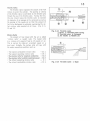
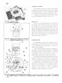
The P-50 is a gasoline engine powered bicycle, affording all the simplicities of the bicycle
with the powered features of a mopet, yet so
easy to handle that anyone who Is able to ride a
bicycle can ride the P-50 without any previous
-
experience. It is designed to fulfill the need for a
safe, economical and easy handling family transportation.
This manual has been prepared as a servicing guide for the P-50, and all personnel who will
be servicing the P-50 should read this manual
carefully to become familiar with all of its sections.
The manual is written in tow parts, construction and maintenance inspection, for easy reference.
Any revisions to this manual will be notified
by the Service Bulletin.
July 20, 1967
Service Department
Honda Motor Company Ltd.
I
II
1.
2.
CONTENTS
II
FEATURES
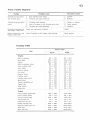
SPECIFICATION & PERFORMANCE
SPECIFICATION FOR P - 50
. .. . . . . . . .. . .. . . .. . . . . . . . . . . . . . . . .. . . .. . .. . . . . . . . . . 2
DRIVING PERFORMANCE CURVES .. . . .. . .. . . .. .. . . .. .. .. .. . .. . . .. . .. . . . . . . 4
ENGINE PERFORMANCE CURVES .... ..................... . ................... 4
WIRING DIAGRAM . . . . . . . . . . . . . . . . . . . . . . . . . . . . . . . . . . . . . . . . . . . . . . . . . . . . . . . . . . . . . . . 6
(For General export type) . .. .. .. .. . .. . . .. . . . . . . . .. . . . . . . . . .. . .. . .. .. . . . . .. . .. . . . . . 6
( For U. S. A. export type)
. . . . . .. . .. . .. . .. . . . . . .. . .. . . .. .. .. .. . .. .. . . . . .. . .. .. . ..
7
(For France and Belgium export type) .. .. . .. . .. . . . . . .. . . .. . .. .. . .. . .. . .. .. .. .. 8
(For Holland export type) . . . . . . . . . . . . .. . . .. . . . . .. . . . . .. . . . . . . . . . . . . . . . .. . . . . .. . . ..
8
(For England export type) . . . . . . . . . . . . . . . . . . . . . . . . . . . . . . . . . . . . . . . . . . . . . . . . . . . . . . . . . 9
(For Germany export type)
.. . . .. .. . .. . . .. . .. . . . . . . . . . .. . .. . .. . .. . .. . . .. . .. . . . . . . 9
DIMENSIONAL DRAWING ....... . ............. . .......... . ... .. .. ... . ... ....... 10
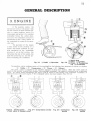
GENERAL DESCRIPTION
3.
ENGINE
Operation of Four-cycle Engine
.. .. ...... .... ..... ...... . ....... . .. . ........ 12
Intake (Intake of the fuel-air mixture)
.. ..... . .. . .... .... .... ...... .... 12
Air Cleaner . .. .. . .. .. .. ..................... . .. . ..... ... .. . . .. . .. .... ..... .. . . . . .. . ...... 12
Fuel Tank ... .. .... . . .. . .. ... . . . .. . ... . ....... . .. . .... . .. . ... . .. .. . .. . . ..... . .. .. . ......... 13
Fuel Cock ............ . . . . . ... . .. . ......... . .. . ... ...... . ... . . . . ....... .. . .. .. . ............ 13
Carbu retor
. . ........ .. ...... .. . .. . ...... . .. . . .................. .. .... . . .. .. . . .... . .... .. 13
P-50 Carburetor Construction ......................................................... 16
Operation of P-50 Carburetor Component Parts ................................. 18
Compression (Compress the fuel air mixture in the cylinder) ... 19
Piston ........... ....... .. . . ... . ... . .. .. . .. . . . .. . .. ...... .. .. . ..... .. . . ....... ...... .... . ... . 19
Piston Offset
......... . ..... ... . .. . ........ . ....... . .. . ............ ....... . ... . . .. . ... . 20
Piston Shape . ..... . .. . .. . . .. .. . ... . . ...... . .. . . . . .. . . .. ... . ... . ... . .. . .. . .. . . .. . . .. . ...... 20
Piston Rings ...... . .. . .. . ..... ... . . .. . ... . .. . . ......... . . .... . . . . .. .. .. . ... . .. .. .. . ....... 20
Cylinder ...... .. . .............. . ...... . ... . ... . ...... . .. .. .......... .......... .. . .... .... ... 21
Combustion (Ignition of the compressed air-fuel mixture by
the spark plug to cause combustion) ................. ................. ..... 2 1
Ignition System ............... .. .. .. ...................................................... 21
Flywheel AC Generator ... ....... ....... . ............. .. .. . .. ... ........ . ... ....... . .. 22
Ignition Coil ............................... . . ......... . . . .. . ......... . ....... .. ........ . .. 22
1
I
FEAT~~
Engine
1.
CHAIN DRIVEN 0. H. C., 4·CYCLE ENGINE is used to provide quiet efficient power.
2.
POWER TRANSMISSION IS PERFORMED by a specially engineered three st age speed
n'!duction and a reliable centri fugal clutch that automatically disengages at idling speed
and engages when throttle is opened ; eliminating any need for a manual clutch or gear
shift.
3.
ENGINE STARTING AND STOPPING is by opening or closing the decompression lever
which relieve the compression from the cylinder.
4.
THE ENGINE AND THE COMPLETE POWER TRANSM ISSION UNIT are contained within
the rear wheel hub together with the rear brakes.
5.
SHIFTING THE CYCLING LEVER located on the engine disengages the engine to permit
pedal operation of the P·50.
6.
CHOKE BUTTON IS CONVENIENTLY LOCATED on the steering head, accessible while
riding.
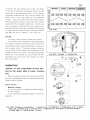
Frame
1.
A STEP THROUGH FRAME WITH A LOW CENTER·OF·GRAVITY makes it easy t o mount
or dismount and provides for greater stability.
Frame main structure is a monocoque,
welded pressed steel sheet for high strength and ridgidity.
2.
EXPANDING BRAKE SHOES in the front and clamping band brakes in t he rear operated
independently by the handle levers assure good braking .
3.
AUTOMATIC ARM CHAIN TENSIONER constantly maintains the pedal drive cllain in proper
t ension, eliminating any need for ad justment.
4.
THE EASY STEERING BICYCLE TYPE HANDLEBAR is vertically ad justable.
5.
A CONVENIENT BASKET IS MOUNTED ON THE FRONT FORK for carrying shopping or
u Llit:!r ligill luetu.
r
2. SPECIFICATION & PERFORMANCE
1
SPECIFICATION FOR P-50
Specif ications
De scription
Name of motorcycle
Model type
Type of vehicle
Honda
p.so
Motorcycle
Dimen sions
1,730 mm ( 68.2 in) ( For Holland)
Over all ler1 g th
1,'570 mm ( 65.7 in)
Over all width
620 mm (24.4 in)
Overall height
1,020 mm (40.2 in)
1,070 mm ( 42.4 in)
1,050 mm ( 41.4 in) ( For Holland)
1,090 mrn ( 42.9in) ( For Holland)
110 mm ( 4.3 in)
130 rnm ( 5.1 in) (For Holland)
Wheelbase
Min. ground clearance
Weight
46 kg (101.3 lbs) (For Holland)
13 kg ( 28.6 lbs) ( For Holland)
Weight, empty
Empty weight distribution, front
Empty weight distribution, rear
45 kg ( 99.1 lbs)
Full load weight distribut ion, front
29 kg ( 63.8 lbs)
33 kg ( 72.7 lbs) (For Holland)
37 kg ( 81.5 lbs) (For Holland)
Full load weight distribution rear
71 kg (156.41bs)
84 kg ( 185 lbs)
14 kg ( 30.81bs)
31 kg ( 68.3 1bs)
(For Holland)
Perform once
Max. speed
Climbing ability : grade
40 km/ h ( 25 mile / h)
37 km/ h ( 23 mile / h)
5 °10'
Engine
Type fuel used
Gasoline
Type engine
No. of cylinder and arrangement
Air cooled 4 stroke cycle
Single cylinder, tilted up 10° from horizontal
Valve arrangement
Total piston displacement
49.3 cc ( 3.0 cu. in)
o;;c
and valve
Bore x Stroke
Compression ratio
42 X 35.6 mm ( 1.65 X 1.4 in)
Compression pr essure
12 kg / cm2 (17llbs/ in2)
Max. output
Max. torque
Min. fue l consumption at max. load
0.25 kg·m ( 1.81 ft . lbs)/2,800 rpm
270 gr / Ps·h / 2,900 rpm 350 g r / Ps·h/ 4,000 rpm (For Holland type )
8 .7 :1
1.38 PS / 5,000 rpm
cx 278 w x 310 h ( 15.6 x ll.OX 12.2 in)
Dimension (mm)
396
Totar weight
Installation and method
12 kg ( 25.4 lbs)
Start ing method
Carburetor No. and type
Pedal starter
Single, dawndraft
Air filter t ype
Dry (urethene foam)
14 kg (30.9 1bs) (For Holland type)
Mounted on rear wheel with torque link
Fuel tank capacity
2.51it. (0.7 US gal .. 0.6 lmp. gal.)
Lubrication method
Lubrication system capacity
Splash
0. 7 lit. ( 1.5 US pint, 1.2 Imp. pint)
3
Description
Specifications
Ignition system
Ignition method
Fl ywhee l magneto
Ignition coil
High voltage A.C.
Type spark p lug
C·6HB
Power transmission system
Primary reduction method
Sprocke t and cha in
Reduction ratio
2 .74 : 1
Clulcil type
Centr ifugal automatic
Secondary reduction method
Sprocket and chain ( Gear for Holland type)
Reduct ion rat io
6.25 : 1 ( 6.95: 1 fo r Holland type )
Steering system
Steeri ng handle tu rning ra dius
75°
Steer ing handle width
5 70 mm ( 22.4 in)
Caster
66°
Trail
40 mm (1. 58 in) , ( 50 mm ( 1. 97 in) for Holland type ]
Tire, fron t
2.00.17 ( 2PR) (2 3 -2.00 for Holland)
T ir e, rear
2.25·17 (2PR) (2 3 ·2 .25 for Holland )
Brake system
Type brake, fron t
Expand ing brake shoe
Type brake, rear
Externa l clamp ing shoe
Met11od of application, f ront
Right handle lever
Method of application, rear
Lett handle lever
Suspension system
Suspension me t hod, front
Spring
Lighting system
Headlight r ating
6V·l5W ( For U.S.A. type)
6V-10W ( For General expor t , England type)
6V-6W ( For Fr ance, Belgium, Holland type)
6V-1 5W ( For Germany t ype)
Tailli ght rat ing
6V -5.3W ( For U.S.A. type)
6V-3W ( For Gener al export . England type )
6V-1.8W ( For Fr ance, Belg ium. Holland type)
6Y·l.8W ( For Ger many)
Stoplight rating
6V-17W (For U.S.A. type)
6V -8W ( For Genera l export , Engl and type)
bV-5W
( ~ or ~ranee.
Belgium type)
4
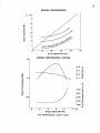
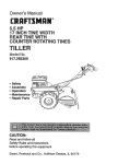
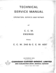
DRIVING PERFORMANCE CURVES
8
3
X
10
15
7
,.....
:E
I:L
6
.,
5
4»
4
~
Q)
Q.
,.....
-..
0)
..:.::
10
Q)
u
0
1.&..
0)
UJ
c
>
..
3
Q)
c
5
en
c
2
c
I.LI
1
0
10
20
30
40
50
Running Speed (km/hr)
ENGINE PERFORMANCE CURVES
1.5
0.4
Q)
:I
0.3
IT"
oE
~·01
0.2
,....
cri
.::~
ns
.:
0.1
1.0
~
0
--
0.:
~
:I
ca.
:I
0
600 c
0
·.;:
500 ca.,....
ns
.c
0
E~
400
0.5
300
200
2
3
4
5
6
7
X
:I
tJj
'
tJj
c ca.
o .......
0 ..
01
4)~
:I
LL.
10'
Engine Speed (R.P.M.)
(General, England, Belgium, France and U.S.A. export type)
5
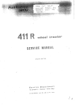
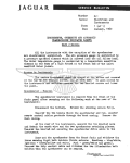
DRIVING PERFORMANCE
7
6
5
4
3
2
10
0
20
30
50
40
Driving Speed (Km/Hr)
ENGINE PERFORMANCE CURVES
1.5
0.4
0.3
u)
-
0.2
a.:
c:
.2
1.0
0.1
•
·e•
-.
-..
E
01
~
41
:I
CT
0
t-
-...
..
..c:
.
ell
c
--CG
Cll
t-
700
:I
D.
600
:I
0
D.
.._
01
c
0
·.;;
D.
0.5
500 E
:I
c
400 "'
0
0
300
Qi
:I
1.1..
2
3
6
4
5
Engine Speed (R.P.M. )
( For Netherlands export type)
7
3
X
10
:-------------]
:
1
R. FRONT TURN SIGNAL LIGHT
-~~~'!!_____ -----,
: l··
i , ,;=J
.
I
I
I
I
o
r------ r-- -- - - -----~
I
.'1'
l']::i§ml' l r
FLASHE~RELAY
~
I
o
TURN SIGNAL SWITCH
i
I
•
UQ···---~~~~~~NIUM RECTIFIER
r · -1···-G\''18
0 :
:II I
~ ,t
0y
I
·,~6V lOW
I
fI
"'
I
:
:
I
:
t
::::
:
nI ~1 :I : 11 ~v ,oI ruer
1
•
I
I
I
I
W~~W'--------~~--------:~~:~:--rr-T;T~l~
-r-::;-t
I
I
I
..
6V8W
I
:
i
I
,
,
I I
L----t-----------~·---G'
fiR
8
•
I
! ::
c ~---c--------+--.
81
:E
I
I
I
I
:
•---- -------------- -~- C'I BK
I
'
IUil'· - _ .,.. (GY B~
_
:
:
J;)
G')
~
I
l
;;
:
.........
'II
0
R. REAR !URN
-- ~- .. J
SIGNAL liGHT
GVF:W
I
·1,·--------------t~t:;~~~~~~~~~~~~~~-~~~~~~=~~~:~~~~:=~~;:~::t~~=~~~~---~~~~~~~;~~~~~=
G')
s:
_ .... --' II
I
I
--r--- -'
-1-----I
...,_ '
c
:::0
l>
:
1
~- -------p
I
' I
TU8[)--- ---- ------- ----
2
I
I
I I
I I
• _ _
$
sl
I
.
I
I
I
·l:tt• ...,...,R- - ----1--,
I
:
1
1-
It
I
i
It~
~
tusr ---- 1
! I : yrk .fUB(:
~"'! 9 l7!t ~
:
HEAD liGIIT
~~~~-~
~f-.:\....--1
L FRONT TURN SIGNAL UGH I I
:I
!
:
! :
I
I
AC. IIORN
W2~
.
R
"r :----·;_.._-_-~~ -------w---J
r--J ........ ........ ............. J
I
~
:
I
..-
1
"' __ ; L... ..,
I
o
0..
FUSE 7A _ _
! :- --~~l!l-·R·-l1Am~-r------:
t
~:::..---:-.: _, .j
..
.
e.
Q
~
:::s
II)
(II
r-
-
_l:_= ~~= ::::J
f Al" i~NITION <Xlll
J
lHIGtl TENSION CABLE
NOIS[ SUPPRESSOR
I
r
)(
'U
......
Bt
J<XJNDEHSER
0
f~
e'
"<
-,
I
.
1
j ;
W
'-?l
/
111
~nll\.111
W
I
I
1
1
.···£0"',\.
\
•
;
-
TAIL/STOP LIGHT
6V 2f6W
• ·-
;
L REAR TURN
;
SIGNAl UGH I
•--·-···---------- -r6V aw
, -r;;;W
IIE£L
A.C. GENERAIOR
!CONTACT BREAKER MOUNTED)
;
NOTE(---) lndicalc optiOnal Paris.
'U
It
"'-"
LIGHTING SWITCH SWI TC HING ARRANGEMENT
~
-------
_ 6Vl8W
I1
-
I
FRONT. RIGHT
~
~
TURN SIGNAL SWITCH
TURN SIGIIAL LICHT :
IIO~fl Sl'li!C~
FUSE
>-
~
:
I I
I
I :
:
ii
a:>
"L \
I
l:
~
I
~
:
~ I 1
~
=-I 1
"" I
GW
cc I
"'
I
I
__
I
I
I
I
1
I!:J
I
R
I
:
.---------.,
BR
BR
G--=-G
1
I
I
I
n) :Lr~
l - ~ :i ____
,:
6V4AH
~
T SWITCH
1
ER--=-R·
!
\
l
-----cv-c::r-cY
, G-c>-G -
\
- ·
L R-<:J-R-
\
J - --
I
I
'-{- _:::t _·:::::.- :::::·LBL::B-LBL
------~
r --- 0·..._----- 0
:
•
R
~~
I
'-·
~
~a>
0
SELENIUM -
l
RECTIFIER-
I
L_____________
·-
.I
l
..
":"
I
(D
I
-----~w
L-
:
BK j
,.
)C
I
I
_J
"'
0
"I
~
:
y -<=!. _.._
..-....
~
1-1-··1 0~·0- ------- -- ,I
I
I
__,_
TURN SIGNAL LIGHi
REAR UFT
'U
0
:t....
'<
'U
CD
'-"
-- --- INDICATE OPTIOnAL PARTS.
"'
STOP LIGHT SWITCil
6VI 8W
TURK SIGM L LIGHT.
FRONT LEfT
Bl
Blll
LG - LIGHl GRHN
\
A.C. IGNITION COIL
-=
fAll LIGII T
\'/
I
r-L'BL~l BL- - - - ----.J
BR-c::>-BR
I
~-------------
6V 17 5 3W
STOP LICHl
I
Y/
:
I
I -
Bl
R
... ~
I I
Q
lOA
J
I I
t::='
R
l
BATTER\
R
l :
3
f
FLA SHER RELAY
HIGH BEAM
6V I 5W 1
IHOICAIOR LAMP (ill
L-:- ~
6VI81¥ lURII SIGNAL LIGHT
RU R RIGHT
r~
BR - BROWN
FLYWHEEL A.C. GENERATOR
G - GREEN
CW
R - REO
BR ' W- BROWN WHilE
G Y - GREErl YELLOW
GY - GREY
LBL - LIGHT BLUE
·CONTACT BREAKER MOUNTED
':"
0 - ORANGE
W
WHITE
BK - BLACK
CREE~
WHil E
"'
8
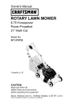
(For France and Belgium export type)
HOR!iSWITCH~
0
<CJ
·
cv- - ---,
A.C. HORN
STOP LIGHT
6V-----""'
SW \
,---:
\
LIGHTING SWITCH
'
'
!
I
0
'
/
"TAILLIGHT""'
6V l.8W
HIGH TENSION CABLE
( For Holland export type)
' ' - - - - - - - :_;--:-:
__:::_=- -=-=-=
-~
------W-+-----BR---c:=r-BR'----.....1
~
-.
fCONDENSE~
BK
~
~~
- _
C
i!hmrON
COIL
HIGH TENSION CABLE
~
y
GR
LIGHTING SWITCH SWI TCHINGARRANGEMENT
,,
1
c,
z
HL
Y GR
rl
- -- _
//~;~
•
~\
: ~- lJ :
\....pT
4
._Jf'/
Off
ON
C, I
c.l SL
-o-f-0 ' ~
/ FLYWHEEL A.C. GENERATOR
(CONTACT BREAKER MOUNTED)
9
(For England export type )
r
Y-=>----GY
HORN SWITCH]_
I
y
A.C. HORN,
LIGHTING SWITCII
·:
')-BRl~-BR~
HEAD~LIGHT l
1
ll>ll
GV lOW
\ '•
...
l~ I
_-.... -TAILLIGHT
6V SW
j ~ J.___v--r_-~_=-_:_,.,_ __ __
- - - - - --
- - - - \ - / - t- - - -BR-«.J-8R----__J
~K v G R
f coNDENSER
n o
~====::s--~-cmi,-
~K
A.CIGNITION COIL 9
IJ-
\
,'
.----f:::F=
--~...- ~
HIGil !EliSIONCABLE
11 1
YGR
·id. ...~ ,
, ,
;_::J
G1-SPARK PLUG
:::::14
, .j
~-l
~ ~-
"·c:3'mWEEL A.C. GENERATOR
.·-- r ··· (CONTACT BREAKER MOUNTED)
(For Germany export type )
0)SPEEOOMETER LAMP
4'f 6V l.SW
G(!
LIGHTING SWITCH
BR
HEAD LIGHT 6V ISW
IDIN 72601 From Tl
-h-eR
6~R
_,
s~l
~
BR
I
~r--- --
A.C. IGNifiON COIL
C::::~:;:~
I
BK
R
~J
1
SPARK PLUGtM
~
TAIL LIGHT6V SW
{DIN 72601 From L)
BR-L l--HR-----4~3----J:hl
~
J--~~
LIGHTING SWITCH SWITCHINGARRANGEMENT
OFF
ON
' ::SI
r FLYWHEEL A.C. GENERATOR
l . _ _Y (CONTACT BREAKER MOUNTED)
l
10
DIMENSIONAL ORA WING
-
- - (U! ( '( £/06(-
11
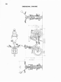
GENERAL DESCRIPTION
3. ENGINE
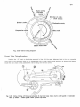
In the gasoline engine. the
fuel and air is mix in the proper ratio
and this mixture is taken into the cyli
nder in a vapor condition where i t is
compressed and ignited, the r esulting
combustion forces the piston down.
ward, and tl1e com bustion pressure is
transformed to the rota r y motion of
the crankshaft by means of the conne·
c ling rod.
T he opera t ion of the eng ine
is quit e sim ilar to the pedaling o f a
bicycle, with power produced by ped.
aling considered as the combus tion
pressure of an air. fuel mixture, the
foot acting the role of the piston, the
pedal the connecting rod. and the spr.
ocket simulating the crankshaft
i l Spark p lug
2 Valve '3' Cyl inder
·~ Piston t!?) Connectingrod ~ Crankshaft
The gasoline engine produces power at the crankshaft by the following four sequence of events, or strokes.
Intake -+ @:; Compression -+ @
Power ---+ @ Exhaust
The term "cycle" is applied to one complete sequence of these four strokes. When the entire cycle of
events in the cylinder reQuires four strok es ( two crankshaft revolu tion), t he engine is referred to as a fou r -c ycle
engine. An engine which accomplishes the en t ire cycl e of events in two strokes (one cranksha f t revolut ion), is
referred to as a two - cycle engine. P-50 is equipped w ith a f our.cyc:e engine. (Fig. 3- 3-6)
Fig. 3-1
(!) Pedal
:g
Sproc ket
Fig. 3 -2
<D
Cit
,®
Fig.3-3
Intake str oke
Fig. 3-4
}:1 Inlet valve g Exhaust valve
Compression stroke
Fig. 3 -5
Combustion
str oke
Fig. 3-6
Exhaust
stroke
12
Operation of the Four-cycle Engine
The four-cycle engine requires two reciprocating sequence of the piston
( two crankshaft revolutions)
to
complete the intake, compression, power and exhaust strokes.
INTAKE
(Intake of the fuel-air mixture)
Air Cleaner
If the air that is used to mix with the fuel is dirty, a great amount of dust and grit enters the carburetor
to cause troubles and they eventually pass into the cylinder to cause rapid wear to the cylinder.
The air cleaner serves to clean the air entering the carburetor.
The air cleane r removes the dust from the air and permits only the clean air to enter the carburetor
through the air cleaner connecting tube. (Fig. 3-7)
Fig . 3 -7
Air cleaner constru c ti on
@ Air cleaner element
;go Co nnecting
tube
@ Carburetor
13
Fuel Tank
Fuel Cock
The 2.5
C
( 5.3 U.S. pt/ 4 .4 Imp. pt.) capaci t y fuel
tank also serves as a luggage car r ier.
A cock is inst-
alled on the fuel t ank to control the flow of fuel from
the fuel ta nk to the carburetor.
@
Fuel is supplied to
the carburetor by gravity feed.
The fuel filler opening is made into a tubular shape
to prevent the fuel from surging out of the cap by
vibration. (Fig. 3 8 )
Fig. 3·8
Fuel t a nk
(1) Fuel f ille r opening ® Fuel
(~) T ool Ki t @ Fuel co ck
(5) T o ca rbureto r
Fig. 3-9
Spra ye r
Car buret or
The ca r bur e lo r perfor ms the rune t ion of m ixing the
fuel wi t h air in the properly propor t ioned m ixt ure t o
form a combustable fuel air vapor.
Shown in f igure 3 - 9 is an at omi zer sprayer for horne
use.
Air blown through t he pipe A increases in veloc ity
as the air leaves the narrow outlet, causing a decr ease
in pressure. The decr eased pressur e draws the water
out of the st and pipe 8 which becomes atom ized as i t
is formed into a spr ay.
The carburetor performs the same funct ion, it dra ws
in the air and atomizes the gasoline.
(l) Water
The fuel which is delivered from the tank first
enters the float chambe r of the carbure tor. Fuel in the
float chamber is always main tained at a constant level
by the action of the float which regulates the v alve. If
there we r e no means to maintain the fuel level constant ,
'(2)
'
the fuel will overflow out of the float chamber or else
there will be insufficient f low of fuel int o the carbure tor.
During the intake strok e of the engine, the inle t
va lve opens, piston moves downward creating, nega t ive
pressure in t he cyl inder. The air r ush es in from the
carburetor.
As air f lows through the venturi, the velocity of the
air increases as i t mOVtlS through the narrow throat and
causes a decrease in pressur e. causing t he gasoline t o
be drawn out o f the nozzle as a sprav and mixes with
the passing air stream. The volume of air-fuel m ixt ure
that enter s the cy linder is regulated by the amount of
opening or closing of the throttle valve. (Fig. 3 - 10 )
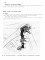
The choke valve is used to permit the carburetor
to supply the engine with the rich mixture required for
star t ing during cold weather.
The choke button is
located at the handle mounting. (Fig. 3 - 12)
Fig. 3- 10
Carbur et or (!J A i r r~; Fro m fuel tank
c ham ber (?) Float ~ Fuel-air mixture
@ Cho ke v al ve (4\ Venturi @ Thr ottl e valve
@ Intake st r oke
@ Fl oat
14
@
---®
5
Fig. 3 -11
Operation of throttle valve
(_l) Throttle grip rg ) Fuel @ Carburetor
@ Throttle valve @ Float valve ® Float chamber @ Float
Fig. 3-12
Operation of choke valve
{I) Choke button
~- Air
@ Choke cable @ Carburetor
15
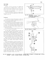
Throttle Vo lve
The throttle valve regulates the amount of air fuel
mixture to enter the cylinder.
The opening or closing
of the throttle valve is controlled by the thrott le grip
through the use of the throt tle cable. Turning the thro-
~
ttle g r ip inward raises the throttle valve to increase
the diameter of air passage in the carburetor as well as
f
the opening of the needle jet so that the amount of
@
fuel to be discharged is reg ulated. maintaining the airfuel mixture ratio constant at all times.
(Fig. 3 11.
13 and 14)
Fig. 3 -13
T hrottle valve
C lose 2 Throttle valve spring
3) Throttle va l ve (4) Cutaway
,5) Jet needle 1§. Needle jet
1'>
Mixture Ra t io
The amount of fuel mixed with the air is called
··mixture
rat io", a weight
ratio.
The typica l r atio
is a mi xtu re o f ! pound o f fuel to 15 pounds of air .
This is norma l for r iding at
level road .
a constant speed on
a
Ac tua lly, the m ixture rat io w ill vary with
the engine operating conditions such as :
The leanest combustible mixture ratio
-+
22: 1
The leanest operating mixture ratio
~
18: 1
-+
1 5: 1
>
1 3: 1
o The mixture ratio f or complete combustion
o The mixture ratio to obtain maximum power
• The richest operating mixture ratio
The richest combustible mixture ratio
_, 8 : 1
·7.5 : l
F ig. 3-14
Throttle valve
(!) Open
16
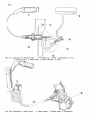
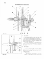
P- 50 Carburetor Construction
Fig . 3-15
1.
Air System
The carburetor use d is a down draft type which
draws the air into the carburetor from the top.
As shown in the figure 15, the air from t he air
cleaner en ters the inlet opening @, passes by the
th rottle v alv e ® and is drawn into the engine artor
passing through the venturi @.
The engine power output is determined by the
volume of air flow which is controlled by the movement of th e throttle valve ® to va r y the opening of
the venturi.
®
2.
Fuel System
The air f low passing through t he venturi ® pro.
duces negative pressure at the restriction under the
throttle valve ®. where the fuel nozzle is located.
Ther e are two sys t em s, the main and the slow system,
in the fuel system.
a.
Fig. 3-16
M ain system
The fuel enters the main jet '.i), and in the
main jet. it mixes wi th the air f rom the air bleed
17
:§) after the air have been metered by the air jet ®. The fuel and air mix ture passes through the opening
between the needle jet '!) and jet needle ® to be discharged as a spray at the throttle valve @. The fuel
spray mixes with the main incoming air and becomes atomized before being taken into the engine.
b.
3.
Slow system
The air which enters from the inlet opening 1; passes around the outside of the air screw ® where it
is metered and then enters the bleed hole @ of the slow jet ~- On the other hand. the fuel from the
float chamber after being metered by the pilot @ and metered again at the jet area @ of the slow jet
iii. mixes with the air from the bleed hole ® within the slow jet and is discharged at the bottom of the
throttle valve '-~ from the pilot outlet @, to mix w i th the main flow of air from the carburetor air inlet
II' and is taken into the engine.
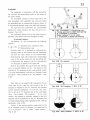
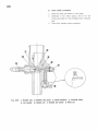
Float Chamber
It is necessary for the carburetor t o supply the proper fue l mixtur e to the engine under all di fferent throttle opening and engine speed: in order to do this. the fuel level mus t be maintained at a const ant level. It is
the function or the float chamber to perform this task.
The fuel from the tank flows through the passage@, passes between the valve seat @ and the float va lve
@, and then enters the float chamber @. As the fuel level in the fl oa t chamber r ises. the float @ becomes
buoyant, float arm @ applies pressure against the float valve forcing it against the valve seat to shut off the
flow of the fuel. When the fuel in the float chamber is consumed, the fuel level drops wi th the consequent
lowering of the flo:st , this causes the float valve to unseat and permi t s the f uel to enter the float chamber.
This cycle is repeated to maintain a constant fuel level @ in the floa t chamber.
4. Overflow Pipe
When dirt becomes clogged in the float valve. fue l overflows from the needle jet and the slow jet. overflowing
into the cylinder to dilute the lubricating oil. Therefore. to prevent a condition where the fuel rises above a
certain level. an overflow pipe ® is inserted in the float chamber to drain any excess fuel. The location of the
overflow pipe is such that only the fuel rising above the overflow opening is drained out.
5. Choke
During cold weather starting, it may be necessary
to init ially use a rich fuel mixture. For this purpose.
a choke valve ~ is incorporated.
When the choke button is pulled the choke valve
is closed. however, there is a relief valve @ installed
on the choke valve and is kept closed by a relief
spring @. When the throttle valve ® is opened ap.
proximately 1/ 4. and the engine pedalled, the cylinder
suction pressure causes the relief va lve to open and
permitting the air to en ter the ca r buretor. As this
air passes the throttle va lve, a nega ti ve pre ssure is
created which dr aws the fuel out of the pilot outet
@ and the needle jet (i) ; mixing wi th t he air to
form a rich fuel air mixtur e ideal f or st arting. This
mixture is taken into the cyl inder for combustion.
After the engine has started, the suction pressure
of the intake air increases, resulting in a corresponding wider opening of the relief valve to maintain the
same rich fuel air mixture.
The opening of the relief valve @ changes according to the opening of throttle valve ~The choke valve @ can be kept completely closed
during warm-up driving and fully opened after warmup. (Fig. 3 17)
®
/ _..®
Fig. 3-17
18
Ope ration of P-50 Carburetor Component
Parts
1.
It meters the fuel flow during full throttle con.
dition ( top speed) to provide a proper fuel mixtur e.
Not only does it function at top speed but it also is
effective to a certain degree at intermediate speed.
The larger the main jet size number, greater will be
the nozzle opening and consequently the fuel flow,
providing a richer fuel mixture. (Fig . 3 18)
\
Fig. 3· 18
Mai n jet
Main Jet
2.
•J, Genuine parts mark
A ir Jet
During full throttle opening. the fuel mixture at
high eng ine speed w ill become rich. and at s low speed
the mixture becomes lean. To prevent such a cond i·
tion, air is bled into the main jet to maint ain a uni
form mi xture. The function of the air jet is to control
the amount of the blee d <:~ir .
As t he air jet becomes larger, the arnollnt of bleed air is increased. resul ting in a lean fuel mixture,
however, at a se t throttle opening, a high eng ine spe.
ed will produce a leaner mixture There is only a
small variation in fuel con sumption between high and
low eng ine speed.
2: M ain jet NO.
3.
Needle Jet
Dunng full or half throttle opening. the fue l which
had beet\ metered by the main jet is ag ain met ered
by thd nee dle jet . The adju stment is per forme d in
conjucllon with the jet needle which is explained in
the following section. The needle jet openin g is made
exceptionally accurate for precise control.
3
Fig. 3-19 Jet needle
Ill Needle clip
(2 Type mark and genuine parts mark
,j , Jet needl e
4.
Jet Needle
The jet needle. in conjuction wi th the needle jet
described earlier. regulates the fuel mixture at the
int ermediate throttle opening (principdlly between
1 / 4 to 3/ 4 throttle opening ). The long t apered jet
needle is located within the center hole of the throt.
t ie valve w i th the tapered end insert ed into the
needle jet. The vertical movement of the thro ttle
valve to which the jet needle is attached controls
the flow of the fuel in r espect to the throttle open.
ing to afford a correct fuel mixture ratio.
There are five clip grooves ( which are counted
from the top) on the head of the jet needle to regulate
the richness of the fuel mixture.
The fuel mixture becomes richer as the clip is
moved progressi vely from the No. 1 g roove to the
No. 5 groove. (Fig. 3 19)
5.
Thr ottle Valve
The f unction of the throt ti e valve is to control
the amount of air taken into the engine : this det er mines t he engine spe ed. the power output, and in
ilddition. performs the impor tant func lion of con troJI.
ing the fuel air mixtu re.
The throttle valve has a cut -away on the air inlet
side.
19
Changing the size of the cut-away ( designated by
cut-away No.) . the pressure actuating the needle valve
can be altered to change the amount of fuel flow and
causes a change to the fuel mixture. The va lve with
a larger cut-away number will produce a leaner fuel
mixture. However, the range of its effectiveness is
mainly at low speed. from idling speed to approxi mately 1/4 throt tle opening and has no effect above
1/2 throttle opening.
A throttle stop screw sets the thrott le va lve in
the idle position. Screwing in on the stop screw
will cause the throttle valv e to rise. and backing off
will lower the throttle valve.
6.
Slow Jet
1 he slow jet regulates the fuel flow during idling
and small thrott le opening, and perm its t he air to
en ter throu gh the air bleed to m ix with the fuel for
atomization. The slow jet is similar to the main jet
in that the lar ger t he jet size number, the great er
will be the luel flow and consequent ly a richer fuel
air m ixtur e. ( Fi g. 3-20)
7.
Air Scre w
The air screw regulates the amount of air m1x1ng
with the fuel in the slow speed system by controlling
the amount of pilot air bleeding with the fuel entering throu gh the slow jet. In this way, the proper
fue l air mixture is maintained. Screwing in the air
screw w ill produce a rich fuel-a ir mixture by restrict·
ing the air bleed hole and backing off on the screw
will resu l t in a lean mix ture.
Fig. 3-20 Slow jet
'!) 0 ring
2 Genuine parts mark
'3 Slow jet ® Sl ow jet NO.
l
COMPRESSION (Compress the fuel air
mixture in the cylinder)
Piston
The piston plays an important role by performing
the intake, compression, power and exhaust funct ions.
It is alternately cooled by the intake fue l-air mixture
or exposed to the ho t gases resulting f rom the combus tion. If the piston is close ly fi tted agains t the cyl inder wa ll w i thou t clea ranc e as shown in the ri g. 3 2 1,
it would not operate smoothly and may result in seizure.
On the other hand, excessive c learance between the
pis ton and cylinder wall will result in insu fficient intake
of ruel -air mi xture, causing low compression, oil pumping (oil enters the combustion c11amber ) , etc .. and
conseQuence poor engine performance. Therefore, a
good seal must be maintained between the pis ton and
cylinder wall. For this purpose, piston rings are installed to provide the necessary seal.
The piston is made of aluminum die cast ing equivalen t to SAE 8630. This ma teria l is light and has good
heat conducting proper t y so th at tile heat f rom the
combust ion can be dissipate rapidl y. Fur the rmor e, t his
mater ial has a small coeffic ient of expansion, thus
minimiling the expansion o f the piston at elevated
temperature and permits a small piston to cylinder
clearnace design.
Fig. 3 -21 Piston
1 1 Cylinder
'2) Piston
(3 Piston rings
20
Piston Offset
As shown in the figure 3- 22, the piston pin is offset
slightly from tile piston centerline.
This is to reduce
the side load against the cylinder wall and by so doing
pr event piston sl ap. (Fig. 3 - 22)
Piston Shape
The shape of the piston is an ellipt ical taper. This
is because the head of the piston, compared to the
sk irt, is expose d to much higher temperature and since
Fig. 3·22
the expansion is g r eate r, i t is tape re d smaller towa rd
(!) Offset
the top.
The taper ing of the piston also tends to les -
sen the pis ton slap when th e throttle is ligh t ly snapped
at light engine loading at low speed. (Fig 3- 23)
Piston Rings
Usually t hree piston r ings are ins talled on t he piston.
St artin g wi th the top, they are ca lled the top r ing,
second ring and oil r ing.
Th e top and se cond rings:
Serve as a seal for the combus tion chamber and
Fig. 3 -23
Piston configuration
also to t r ansmit the high temperatur e of the piston
to the cy linder wall where it is dissipated t hrough
----®
the cy linder cooling fins.
The oil ring :
Serves to scrape off excessive amount of oil from
the cylinder wall and to prevent oil from entering
the combustion cham ber.
To pr event flutter. the rings ar e made narrower in
w id th an d incr eased in t hickness so that the inertia is
decrease d whi le t he r ing pressure ag ainst the cy linder
wall is incr eased.
Fig.
~-24
Piston ring
U) Top rin g
@ Second ring @ Oil ri n g
rings are made
Further the top and t he second
at a sligllt taper where it contact the
cylinder wall so that the time required for swear-in is
lessened.
The g roove in the oil r ing as well as the bevel of
the second ring serves to assist oil scraping and preven t s oil from penetrating into the combustion chamber.
Thus, ca rbon deposit on the plug. piston r ings, etc.
is prevented and t he oil consumption kept to a minimum.
(Fig. 3 2 4 )
Piston Ring Flutter
A t low spe ed, the piston r ing is forc ed agains t the
upper side of t he ring g roove only during the intake
Fig. 3-25 (i) Piston
~ Piston ring
@ Blow-by
stroke. At high speed, however, t he inertia o f the ring
21
overcomes the
gas pressure and friction, and floats
to the top of the groove immediately before the topdead-center in the compression stroke. At this moment,
combus tion occurs and the ring is forced against the
bottom side of
pressur e.
the r ing g roov e by the combust ion
This up and down movement during exhaus t-
intake-compression becomes more
and mor e intense
coupled with the incr easing inertial force.
As this seq-
uence is repeated , ultimate ly, the ring vibrates violently within the ring groove like a pingpong ball between
the racket and the table as shown in the figure 25 and
co
F i g. 3 -26
thus allow the gas to ·• blow-by ". (Fig. 3 - 25, 26)
Cylinder
The piston cannot operate without the cy linder.
The cy linder wall is exposed to high temperature
and pressure togethe r w ith th e wearing action of t he
rec iprocating piston moving at high speed to produce a
great wearing effec t.
Therefore. adeQuate attention
must be g iven to the ma terial and construction of the
cylinder as well as the piston.
The cylinder has m an y
cooling fins on the outside so as to increase the heat
Fig. 3 -27
Cylinder
®
Cooling fin s
dissipating area and preven t the cy linder and piston
from overhea ting.
COMBUSTION
1_@
(Ignition of the compressed air-fuel mixture by the spark plug to cause combust ion)
When the piston reaches the top-dead-cen ter at the
end of the compression stroke, the compresse d air-fuel
mixtu r e must be ignited.
Ignition System
Magneto system
a
FlywhP.P.I magnP.to (rotating permanent magnet)
b.
Box magneto
P 50 incorporates a flywheel magneto (flyweel AC
generator).
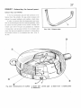
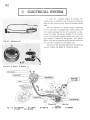
Fig. 3-28 Flywheel A . C generator (!) Ignition coil ® Condenser @ Hightension cord AJ Spark
plug cap @ Spark plug (61 Pri m a ry coil (!) Lighting coi l ~ Ground ® Contact breaker
10 H ead light .g Tail/ stop l ight 12) H orn
22
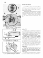
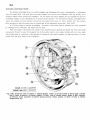
Flywheel AC Generator
By rotating the flywheel (permanent magnet) ,
electrical current is generated at the stationery primary
coil. The primary current of this voltage is interrupted
by the contact breaker to produce a high tension vol
tage from the ignition coil.
This high.tension voltage is transmitted by t he high
tension cord
to produce a spark at the spark plug
which ignit es the air fuel mixture. The flywheel magneto
in addition
to the primary ig nit ion coil
incorporates
the lamp coil for ligh ting use to oper atP. lamps, l1orn,
etc.
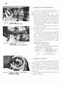
Fig. 3-29 Flywheel A . C. generator
ll F l ywheel ,2 Groove '-~ Contact breaker
4 Primary coli ::?') Lighting coi l
Ignition Coil
Fig. 3-30 Ign i tion coi l (l Primary wire
? H igh tension cord j\ Condenser
The ignition coil is composed of a primary coi l
having approximately 300 turns of 0.44 mm (0 .0 l 7 in)
diameter enamel or polyes t er coate d co pper w ire and
a secondary coil having 20,000 turns of 0. 06~0.07 mm
(0 .0024-0.0028 in) diameter enamel or polyester
coated copper wire wound around an iron core.
Essentially, it is a transformer to change the 6~
12 V pr imary voltage to J 0,000-15,000 V secondary
voltage. The change in the magnetic flux due to the
sudden opening and closing of the contact breaker
points in utilized to generate high voltage.
The ignition coi l is located in the frame where it is
not restricted as in c ase of being installed in the flyw.
heel and where it is not directly affected by the heat
of the eng ine. Further it is accorded adequate cooling.
The ignition coil is made durable and of heat re .
sistant material. This grea tly assists in prolong ing th e
service I if e of the breaker points. (Fig . 3- 30)
Breaker Points
Fig. 3·31
point
Contact breaker p oi nt (i) Breaker
6. Breaker arm r3, Crankshaft
The breaker points interrupt the primary circuit of
the igllition coil. Points are kept closed by force
of the spring and opened by the breaker point cam in.
corpora t ed in the hub of the flywheel to interrupt the
primary ci rcuit.
At this moment. induction occurs at the primay coil
and the high vol tage is induced in the secondary coil
in proportion to the number of windi.1gs in the coils.
23
Condenser
In a household electrical circuit. i f the circuit breaker
is opened. sparks will be noticed across the poin t s.
Similarly, when the breaker points are opened. sparks
are produced in most cases. This prevents the sudden
collapes of the primar y circuit and thereby reduce~ the
high voltage reQuired for the secondary coil and fur ther
causes sparking across the point which eventually resul ts
in burning or pitting of th e breaker points.
The con.
denser is installed in parallel across the breaker poin t s
to pre vent this undesirable condition.
Condenser can be considered as a device to store
electr i :i ly.
d::::::.-----==---==--=--=-- ---=-
I t is made from shee t s of mica or paraffin
paper and tin foil in al te r nate
==--::_-_-;_----====-==
layer. (Fig . 3 32)
Fig. 3·32 Construction of condenser
! ) Mica 4 Tin foil
Spark Plug
The spark plug plays the role of igniting the compressed air-fuel mixture within the cylinder. The spar k
p'ug is securely sc·ewed in to t he cylinde r head with a
gaskel installed. It is exposed to high voltage. high
compression and high temperature· hence, high streng th,
heat resistance and r eliabili ty are essential.
At
the end of the plug are located the center
elec trode and the g rounded side elec t rode with clear ance of 0 .6-0.7 mm (0 .024-0.028 in) between the
@
electrodes.
If the spark plug clearance or gap is too wide. re.
sistance to th e high
vol ta~e
to bridge the gap
is
increased and pr events the spark from being produ-
.@
ced: it the plug gap is too narrow , a short is likely to
occur due to ca rbon deposi ts. and in whi ch case, a
misfire wi ll resul t.
There fore. the plug gap should be
maintained at the specified clearance and the electrode
surfaces always be kept clean.
The high vol tage pro-
duced by the Igni t ion coil is rece ived by t he spark plug
and causes
a hot spark to jump across from t he center
electrode to the side electrode and ignites t he con bustible mixture within the engine combustion chamber.
r®
_ - ---~: 0 .6-0.7mm
(0 .024-0 .028 in )
Fig. 3 -33 Construction of spark p lug
1 T erminal 2 I nsulator 13 Filler powder
4 Wire packi ng
5 Center electrode
§) Wrenching surface ( hex) ] ' Gasket
s' Main body 9 Elec tr ode }9 Spark ga p
24
N oise Suppressor
Oscillating curren t which includes high freQuency
wave g enerated in the high t ension ignition circuit ra.
diates from the high voltage circuit and the frame body
@.
and causes interference (by causing noise. distortion to
image)
to the tele vision set, radio, etc.
To prevent
@
this, a noise suppressor. is installed. It incorporates a
@.
carbon resistor. as shown in figure 3 4 . within a se aled
case.
Fig. 3-34 Sectional view of noise suppressor
(!) H igh tension termin a l bushing @ Terminal
water proof cap @ H igh tension terminal
cap ® Shield case @ H igh tensi o n termina l
seal .§) Earth band (j) Carbon resistant
The carbon r esi stor funct ions as an attenuation
resistor and the sealed case serves to help prevent
high frequency radia t ion in conjuction with the c arbon
resis tor. (Fig. 3 ·34 }
Automatic Spark Advancer
P 50 Rear wheel output power
To obtain the most effec t ive use of t he combus.
Comparison of governor controlled and
uncontrolled power output.
t ion pressure. the timing of t he ignition must be advance
Using :
Cerburetor
MB 8mm MJ52
Tire prHSUre 1.8 kg /em•
Governor spec. : 5' spark advance at
4800 ± 50 RPM ml n.
t8' s park advance at
5300 ::: 150 RPM
as the engine speed increases. Considerable time will
lapse before the combustible fuel mixture is comple t ely
burned after being ignit ed and the m aximum combus.
tion power is produced.
The movement of the piston
is very rapid and if the ignition should take place when
...
the piston is a top-dead-center, the combution will ta ke
~
place after the pis ton has started its downward move.
;;
ment and th e maximum uti lization o f t he combust ion
..
1!-
"
pressure cannot be rea lized.
0
Therefore, the bre aker
points sltould open to produce the spark ignition just
prior to the piston reaching top-dead-cente r. and as the
engine speed increases. the ignition must take place
that much earlier .
Normally, ce ntrifugal force is used and the amount
of ignition advance is automat ically controlled by the
20
25
30
35
40
engine speed.
45
km/H
(~~)(~:) (~~)
Speed
Fig. 3-35
---Performance curve
This type advancer is known as the
automatic centri fugal spark advancer.
From the standpoint of safety, t his automatic spark
advancer is employed as a speed governor in th e P50.
Up to the engine speed of 4500 RPM .. the ignition will
advance to 28• before top.dead.center. however. as the
speed increases beyond tnis point, the governor will
start reta rdin g the amount of spark advanc e until at
5200 RPM, the ignition will take place at 1o• before
top-dead-center and t his will hold the speed of t he
motorcycle to maximum of 30 km/h.
The P 50 is, in
this way controll ed to operate at the speed of maximum
economy and perfor mance whic h is 4500 RPM (25 km/h) .
(Fig. 3 - 35, 36)
Fig. 3 -36 Governor operati on (!) Govern or
oper ating <2) Spri ng (For Holland export)
25
Crankshaft
The crankshaft. in conjunction with the connecting
rod, converts the reciprocating motion of the piston to
the rotary motion.
The crankshaft consists of three major par t s, the
right crankshaf t . left crankshaft and crank pin; which
are assembled int o an integral unit by press fitting. It
is supported at the both ends wi th 6202 ball bearings.
The right and left crankshafts, are proportional ly
balanced to reduce vibration and they also serve as a
flywheel. (Fig. 3 37)
The crankshaft balance affects the riding comfort.
therefore, this balance has been designed to 60%.
Fig. 3 - 37 Crankshaft (i;) Connecting r od
2) Timing sprocket @ 6203 ball bearing
! 1 R. crankshaft ~ Crankpin
16 ) Roller retainer 'z) 2 X 8- r o ller
@ L. Crankshaft ~ 6202 ball bearing
(Crankshaft Balance)
The balance "A" (%) is computed by t11e follow ing
equation:
A
m
M
>; 100
m : Gyrating mass (unbalance value)
M: Reciprocating mass
Gyrating mass (m) is obtained by subtacting t he
y
gyrating mass of the crankpin and the connecting
rod from the total weight of the counterweight.
Reciprocating mass (M) includes t he reciprocating
mass of the piston, piston pin, and connecting rod .
ll det e rmines the balance in the X· X direction and
Fig. 3-38
0 % balance
'Y·Y direction as shown in the figure 38.
Firs t of all, consider the case in which the rotating
unit is in perfect balance (m = O).
The inertia in the
direction of X·X produced by thP, reciprocating mot ion
of M acts intermittently, and sets up vibra t ion within
the engine.
This is referred to as "0% balance". (Fig.
3 38)
y
y
Next, 30% of the weight of M is placed on the op.
posite side of th e crank pin. the inertia in the X-X
Fig. 3-39
30% balance,
<D
30% of M
direction is reduced to 0.7 x M. However, the rotating
section becomes unbalanced (rn =-0.3 x M). and vibra.
tion is set up in Y·Y direction due to the centrifugal
force.
This is called " 30 % balance".
To be more
specific, the amount of vibration reduced in the X-X
direction will be transferred to the Y·Y direction with
the total always being equal regardless of the rat is of
y
distribution. (Fi g. 3 39)
Further. if the counter weight is made equal to the
M, all vibration in the X·X direction is transferred to
the Y·Y direction.
(Fig. 3 40)
This is called "100% balance··.
Fig. 3 · 40
100% balance,
® 100% of M
26
Combustion Chamber
The combustion chamber of P-50 is heart shaped.
this allows the cyl inder head to be made more compact
in comparison w ith the spher ica l combust ion chamber.
and is possible to obtain a higher compression ratio.
In addition. its ccnstructed affords better cooling
as we ll as combust io:1 efficiency. ( Fig. 3 41 )
Fig. 3-41 Cylinder head
Q) Combustion chamber
Squish area
This is an area provided betweun the piston and
the cylinder head to further compress part of the fue l
air mixture at the end of the combustion stroke to
c r eat a turbul ence within the main fuel m ixture. As the
swirling fuel m ix tur e is diver t ed toward the spark plug
the flame propagation is accelerated. allowing t he the
leaner than normal fuel-air ratio or the slowe r burnmg
fuel mixtur e to burn smootl1ly, and decreasing the tendency for knocking. ( Fig. 3 - 42)
Squish area (!) Valve 1?. Combustion
chamber (3) Squish area
Fig. 3 -42
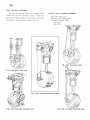
Connecting Rod.
The connecting rod plays the important
role of
conve rting the r eciproca t ing motion of the piston caused
by the combustion of air -fuel m ixtur e to the rot ary
,
,,
- ·®
@
,
'
It also transmits the iner t ia from the cr ankshaft to
tile piston so that the intake. compession. combust ion
·@
and exhaust stro kes can be per forme d. T he m aterial
of construction must be light and r ig id: therefore, ''I"
p
'p
mo tion of t he c rankshaft .
-@
shaped nickel chrome s t eel is used in most cases.
The piston end is callt:!d the small end and is conn·
ec l ed by a pis ton pin and locked wi th snap rings to
preven t the piston pin from moving in the axial direct ion.
The cranksha f t end is called the large end. The large
e 11d is fitted with the needle r oller bearing tn r P.ciuce
friction and is assembl ed on the crankshaft with the
crank pin. An oil splasher
at tached
to
the large end
in shape of
a scoop is
to splash lubr icat e the
crankshaf t , cy linder and pis ton. ( Fig. 3 43)
Fig. 3 -43 Operation of connecting rod (l Cylinder l £ ) Snap ring (~; Piston pin ~~; Piston ,5) Connecting
rod (6' Roller retainer (J; Crank pin (§1 Timing sprocket ~~· Crankshaft •10• Oil splasher [1; Crankshaft
(R. L )
27
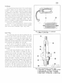
EXHAUST ( Exhausting the burned gases)
Exhaust Pipe
and Muffler
If the hot combustion gas and high pressure is ex hausted from the cylinder, the gas under pre ssure will
attempt to expand suddenly and produce a loud noise.
In order to preven t t his, t he t emperat ure and pressure of the burned gas must be reduced gradually, m ust
be routed from t he cylinder t o the muffler through th e
exhaw;t niPP. whP.rP. t hP.
211~
r.an gradually by reduced
in temper ature and pressure be for e i t is exhaus t pipe
Fig. 3-44
Exhaust pipe
wher e the gas can g r adually be r educed in t emper atur e
and pressur e befor e it is exhausted out side. ( Fig. 3
44, 4 5)
Fig. 3-45
Construction of muffler
j) Outer half
<Jj) Separator
@Inlet pipe
@ Steel wool
'4) Guide plate
28
Valve Operating Mechanism
The inlet and exhaust valves are installed in the
cyl inder head of the four-cycle engine.
These are
opened and closed to assist in performing the intake,
compression, combustion and exhaust functions
Types of valve operating mechanism
Side va l ve ( SV) type
Overhead va lve ( OHV) type
Overhead camshaft ( OHC)
Chain type
Gear type
Fig. 3 -47
Overhead valve
type
Fig. 3 -46
Side valve type
Fig. 3-50
Fig. 3-48
Overhead camshaft type
Overhead camshaft type
Fig. 3-49
Overhead camsh aft type
29
Overhead Camshaft
When the part shown in the figure is revolv ed, t he
vertical rod moves u;> and down. ( Fig. 3 - 5 1)
The camshaft installed the cylinder head i s r e.
volved by the timing sprocket installed on the crank·
shaft through the cam chain. The c amshaft actuate s
the rocker arrns by providing a rocker movement which
operates the valve. In order to maint ain t he cam chain
at a specific tension so that the val ve t iming is not
effected, a earn chain tensioner is installed wi thin the
crankcase to apply pressure against t he ch ain by means
Fig. 3-51
Principle of cam
of a roller through a spring. (Fi g. 3 - 52)
Fig. 3-52 Over head camshaft mechanism (!) Timing sprocket @ Crank shaft ® 0 mark @ Camchain
tensloner <.~) Camchain f§) Piston \Z) Valve @ Camshaft ® R ock er arm
30
Tappet Clearanc e
The clearance betwe~n the va lve and rocker arm
is referred to as the tappet c learance. Proper clea.
ranee is required for the valve to fully close. If the
clearance is too small. it will keeps the valve from
completely closing, produc ing a low compression ; on
th e o ther hand, if the clearance is too lar ge, tappet
noise resul t s.
The tappet clearance w ill greatl y affects the en.
gine output, revolution and noise. Standard tappet
clearance measured cold is 0.05 mm ( 0.002 in) for
both the inlet ;mrl P.Xhaust va lves. ( Fig. 3- 53)
Fig. 3-53 Valve tappet c l earance (!) Valve
rocker a rm ® Valve tappet clearan c e
@ Cam s ha f t
V alve Spri ng
Without the proper sealing of the v alves maximum
engine output and speed performance ca nnot be realized
The valve spring applies force on the valve to keep
it closed. T he spring force should neither be too strong nor too weak. If the spring force is too weak.
the valve will not close fully , resulting in Joss of com.
pression, exhaust leak, etc; on the other hand, i f the
spring force is too strong, it requires unnecessary
force to oper ate the valves and also cause rapid wear
to the valve seat. (Fig. 3-54)
Fig . 3 -54 Valve & valve spring (!) Valve
® Valve spring
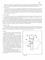
Valve Timing
It may seem to be correct to have the inlet and exhaust valves opening and closing at top-dead-center
and bottom-dead-center.
However, as can be seen from Fig. 3 55, the valves are not timed in this manner. If
the inlet va lve starts to open at top-dead-center , the piston will travel some d istance before the valve becomes
fully opened to take t he air -fuel mixture into the cyl inder. Consequently, sufficient air-fuel m ix ture is no t obtained during the inlet stroke.
dead-center of the inlet stroke.
Therefore, the inlet valve is timed to start opening several degrees before top.
In addition, the inertia will keep the air-fuel mixture flowing into the cylinder
for several degrees beyond the the bottom-dead-center of the inlet stroke.
To take full advantage of the
intake fuel enertia to obtain greater power output from th e eugine, the inlet valve is kept open several degrees
beyond bottom-dead-center.
In a similar manner, the exhaust valve opens several degrees before bottom -dead-center of t he power
stroke in order to utilize difference in pressure between the inside and outside of the cylinder for greater scavengtng of the exh aust gas from the cylinder . 1he valve closes severi:ll degrees past top-dead -center beyond
the exhaust stroke in order to utilize the exhaust gas inertia to completel y r id the cylind er of the exhaust gas.
During the period of several degrees before and after top-dead-center of the exhaust stroke, both the
inlet and exhaust valves are opened; this period is called ·• valve overlap", and it serves to prev ent the resi dual exhaus t gases from blocking the entry of the air-fuel mixture. ( Fig. 3 - 55)
31
Combustion stroke
10°
Bottom dead center
Fig. 3 · 55
Valve timing diagram
Correct Valve Timi ng Procedure
Position the ·· 0 " mark on t he timing sprocket in line with the upper alignment hole in the cam sprocket
when bot h of the alignment holes are in parallel with the cylinder head parting surfarce. as shown in the figure.
Install the cam chain in this position. the valve timing will then be correct.
Fig. 3·56 Va lve timing @Timing sprocket @ 0 mar k @ Case Index mark (4) Oil guide @ Cylinder
head 'ID Chain 1; Chain guide ro ller @ Cam sprocket
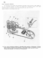
Power
Tronsmission Mechanism
The transmission of the rotating power generated at the engine to the rear wheel is made possible by
the power transmission mechanism.
reducing operations
IS
The P50 is not eQuipped with a transmission, however. all the speed
performed by chains which also drives the rear wheel. (Fig. 3 - 57 )
( Gears are used on P 50 for Holland export type )
Fig. 3 -57 Power transmission mechanism (!J Secondary driven sprocket ,g Riding lever (3 Primary
driven sprocket •4 Secondary drive sprocket @ F inal driven sprocket l6 Crankshaft "tt Exhaust
valve s Final drive shaft 9' Final driven shaft ® Free wheel JL Rear wheel hub J2 Clutch
(Primary drive sprocket) ·~ R crank arm .@ Decompression
33
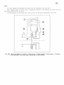
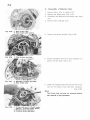
Clutch
The clutch engages and disengages the power from the crankshaft to the rear wheel.
When changing speed. the power must be disengaged temporarily ; when starting, the power must be
transmitted smoothly to the rear wheel.
P- 50 has adopte d the centrifu gal clu tch which performs the operations automatically. (Fi g. 3- 59)
r
I
I
Fig. 3-59
Sectional diagram of clutch \.i) Clutch outer ~ C lutch weight 1j' Drive plate
drive sprocket ~1 Friction plate @ Steel ball •'7> Ball retainer
4 Primary
34
Automatic Centrifugal C lutch
By u tilizing centrifugal force, the c lutch engages and disengages the power au tomatically in accordance
wi th the engine RPM.
The dr ive pla te and clutch we ights are f ixed on the cr ankshaf t . while t he primary dri ve
sprocket rotates freely around the crankshaft.
At low speed. the clutch weights are not actuated so that the
crankshaft rotation is not transmitted to the primary drive sprocket.
As the speed increases. centrifugal force
causes the weights to move outward. overcoming the clutch spring force. to make contact with the primary
drive sprocket so that the power may be transmit ted to the secondary driven gear. (Fig.
In P- 50 the engine is started by pedaling.
3~
60)
Therefore, If the clutch fails to transmit the force produced
by pe daling to t he c r anksha f t . the engine will not start.
When t he pedal is depressed. t he pr imary drive sprocket starts rotating and causes the t hree steel balls
incorporated t herein to apply force against the friction plate which in turn makes contac t with the drive plate
{ the friction plate is restric t ed in the direction of rotation by the clu tch weights) so that the power is trans.
mitted from the drive plate to the crankshaft.
Clutch in 1900-2200RPM
Clutch lock 2800-3200RPM
Fig. 3-60 Sectional view of c lutch 1) Clutch damper rubber @ Friction plate @ Drive plate ~ Steel
ball @ Hook protector @ Clutch weight <Z> Lifter c am @ Clutch center guide ® Ball retainer
Qlj) Primary drive sprocket @ Clutc h spring @' 6mm thrust w asher ® 6mm clr-cllp ® Clutch
weight 6mm pin
35
Engine Disengage lever
By shifting the engine disengage lever, P 50 can
be pedalled. The lever is located at the r ear of
the lef t cran kcase.
By shifting the lever in the vertical direction, the
engine is either engaged or disengaged from the rear
wheel
Engine engaged
>Position the lever to ON
Engine disengaged
•Position the lever to O FF
CAUTION:
Shifting must be done while the engine is
stopped.
Position t he lever to ON
(Engine engaged)
With the lever is positione d to ON, the free pawl
Is held in the g roove of the secondary driven gear
by the force of the pawl spring.
The power from the engine is transmitt ed to the
final drive
sh~f t ,
which rotates the final driven gear
and the fined driven shaf t (coupled to the rear wheel
hub) . ( Fig. 3 - 61 )
Fig. 3·61 Motorcycling (!) Secondary driven
sprocket ® Final drive shaft (3) Free
pawl ® L ower the lever
-
Postion the Lever OFF
(Pedal engaged)
With the lever positioned to OFF, the free pawl
unlocks from the secondary driven gear groove so that
the secondary driven gear rotates freely around the
final drive shaft. Therefore. the power produced by
pedaling rotates the freewheel sprocket and the rear
wheel hub by means of the drive chain and is trans·
mittcd to the secondary driven gear. Thus. the cycl ing
can be enjoyed, similarly as with the bicycle. (Fig.
3 62)
Fig. 3·52 Pedal ing ) Raise the lever
® Free pawl (disengaged)
36
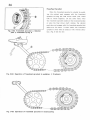
Freewheel Sprocket
When the freewheel sprocket is rotated by pedaling, the ratchet pawl engages wi t h the freewheel
sprocket to bring the fina l driven shaft (rear wheel
hub) to rotate together_
On t he other hand, when
t he freewheel sprocket rotates in the reverse direct ion
or when the final driven shaft rotates. the ratchet
pawl does not engage with the freewheel sprocket but
slides over the teeth_ In other words, the freewheel
sprocket is free when it rotates in the reverse direcFig. 3 · 63 F r eewheel sprocket 1 Ratchet
pole 2• Freewheel spring A
t ion. (Fig. 3 63, 64, 65)
Fig_ 3 ·64
Operation of freewheel sprocket in pedal ing
1' Crankarm
Fig. 3 · 65
Operation of freewheel spr ocket in m otorcycl ing
31
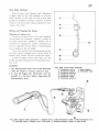
Drive c ha in T ensioner
When the drive chain becomes slack. ad justment
is usually made by the chain adjusters on the rear
wheel ; however, in the case of P 50, a drive cha in
tensioner is installed t o provide a constant. specified
tension for t he drive cha in mak ing ad justment s unne·
cesso ry. (Fig . 3 6 6 )
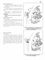
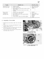
Starting and Stopping the Engine
(Ope ration of e ngine lever )
To start tile engine of the P- 50. star t pedalling,
this will rotate the crankshaft. However , because of
the engine compr ession. pedalling is difficult ; t his is
r+tt--- - -@
overcomed by r eleasing the cy linder compression so
that the crankshaft will tur n ligh tly. A decompression
lever is located on t he lef t handle.
@-
To be more specific, wi th the decompression ;ever
held down, con t inue pedaling until a cer tain speed is
@
attained ; then. release t he lever to start the engine.
To s top the engine, on the other hand, turn the
®- - -
throt tle grip back and depress the decompr ession lever.
(Fig. 3 67)
CAUTION:
Fig. 3·66 Drive
Q) T ensio ner
(2) Tensioner
@ Ten si oner
r4) T ensioner
t5' Tensioner
6 Tensioner
1. The decompression lever must not be depressed
while the engine is running, except to stop.
2. To stop the engine, the
brought to a full stop
motorcycle
before
must be
depressing the
decompression lever.
chain tensioner
arm A
(?,) 6mm washer
spring
(B) Tensloner boot
pivot A
arm B
ro ller
pivot B
I I
\ I
I I
•I
II II ®
I I
..
I I
I I
~
I I
@
Fig. 3 -67 Engine l ever operation '~ Engine lever '2; Decompression cable (3) Decompression arm
(4> Cylinder head r5) Rocker arm (Inlet side) @ Actuate exhaust rocker to open valve
38
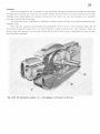
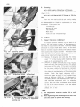
lubrication System
Cylinder Head
Oil from t he earn chain tension er rol ler and the cam chain is carrie d along the c rankcase r ibs to drop in to
the oil guide. from where it is fed to the cylinder head through the oil guide.
Oil enters the camshaft center pin and by centrifugal force is drawn into the spiral groove in the cen t er
pin to lubricate the cam surface as well as the rocker arm slipper surface.
After lubricating t he camshaft, oil passes through the cam cha1n chamber and flows back t o the crankcase.
Oil lubrication system (I ) (i) Rib (? Secondary drive sprocket (3) Cam chain @ Final drive
shaft ~ Rear wheel axle 6) F inal driven sprocket ;7 Rib ~ Cam cllain tensioner roller (9) Oil
Fig. 3 ·68
guide !(! Cam shaft center pin
39
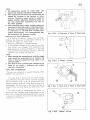
Crankcase
Part of oil splashed by the oil splasher on t he connect ing rod large end reaches the cylinder and lubr ica tes
the piston and the piston pin; while the rest passes t hrough t he cored hole in the right crankcase to the right
crankcase cover, routed along the crankcase ribs into the rear wheel axle hole and lubricates the secondary
drive gear and the final driven gear.
The final drive shaft is lubricated by splashed oil coming through oil holes in the right crankcase and right
crankcase cover.
Even when the <Jmount of oil decreases and conseQuently the oil level in the crankcase drops, the oil
which comes through the cored hole in the right crankcase is picked up by the cam chain tensioner roller and
the cam chain and collected in the oil t ray so t hat t he oil level in t he oil tray is maintained the same to perform the proper lubrication.
Fig. 3 ·69
Oil lubrication system ( II) ~!) Oil splasher @ Oil level @ Oil tray
40
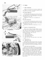
Breather
The interior of the crankcase is continually under
var ying pressure, built up by the reciprocating piston.
in addition, the crankcase is filled with gases from the
blowby of t he piston and the gases produced by the
heat of the crankcase. For this reason, the decomposi t ion of the oil is hastened. Further it also increases t he possibility of oil leaks at the case par t ing
surfaces.
The breather is designed and incorporated in the
case to exhaus t the crankcase gases to the outside
and also to maintain a constan t pressure within the
crankcase. To comple te ly relieve the pressure from
the oil. it is dissipated through the labyrinth. (Fig. 3 - 70)
@
F ig. 3-70
Breather 1 R. crankcase % R. crankcase cover
r~ Dissipate the internal p ressu re t o the outside
41
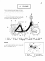
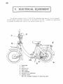
II 4. FRAME II
Frame Construction and Names of Parts
Th e power gene ra ted by the engine is transm itted
to the re ar wheel to produce t he driving force.
An
ideal mo torcycle should be one wh ich is safe and easy
for anyone to r ide.
P- 50 i s of a lightweigh t , strong, low frame type
monocoque body const r uction wh ich has been designed
wi th ultimate in safety cons ideration. ( Fig. 4 1)
(!)
Handle
(!) Front fork
@
Tool box
@
(3) Fuel tank
Maffler
®
@
Saddle
@
CID Rear fender
@J Crank arm
Exhaust pipe
@
Chain case
Front fender
Fig. 4·1
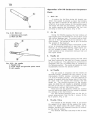
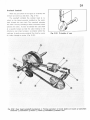
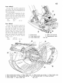
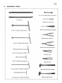
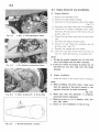
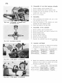
Tool Box
Th e tool box is mounted on the rear of the f uel
tank and contains a spar k plug w r ench, a screw driver
and a lO X 14 spanner. ( Fig. 4 - 2)
CP
Tool box
@
lO x 14 spanner
@
Screw driver
@
Spark plug wrench
Fig. 4·2
42
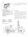
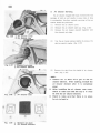
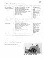
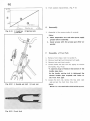
Steerability and Stability
The steerability and stability of a motorcycle de.
pends upon the frame construction. the handle and
saddle heights. and other factors. such as caster and
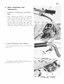
trail which are also important.
Caster is the angle formed by the ground and the
extension line of the frame head pipe. Trail is the
distance measured on the grcund between the vertical
line passing the axle center and the extension line of
the frame head pipe.
Fig. 4·3
:1
For P· 50. the caster is 66° and trail is 40 mm
Caster
@ Trail
( 1.57 in) (Fig. 4- 3)
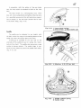
Steering Handle
The steerine handle of P- 50 is identical to tha t
of a bicyc le in shape and method of mounting; however, ·
in addition. i t is eQuipped with a throt tle grip, front
brake lever and a horn button on the right side and a
r ear br ake fever and an engine decompression lever
on the left side.
A head lamp incorporating a speedometer is moun.
ted at the center. and adjustment of the beam can be
made by loosening a nut. (Fig. 4 4 }
J®
Rear b ra ke lever
~
Engine decompression l ever
Head light swit c h
I!
Speedometer
5
@
8)
Horn buttonswitch
9
Rear view mirror
•!9
:n
Throttle cable o u ter holder
12,
Handle lever pivot screw
Fig. 4·4
Front brake lever
Throttl e cable hinge
Throttle grip
Throttl e grip set screw
43
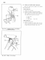
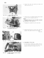
The steering handle is designed for easy riding
with due consideration to the frame size and the saddle
height. ( The handle can be adjusted to any height
within the range marked with L.M.H. stamped on the
handle) . (Fig. 4 - 5 )
Front Fork
The front fork is mounted on the head pipe between steel balls.
T he front cushion, incorporated in the front fork,
dampers and absorbs shocks from the front wheel.
(Fig. 4-6)
..---·~
Fig. 4·5
(1)
Adjustment point
Handle set bolt
@
Handle set nut
Fig. 4-6
@
Front cushion
44
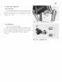
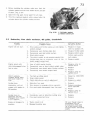
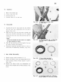
Front Cushion
0
Fig. 4 -7
Telescopic type
(1)
Pine needle type
@
(3'
R's fork type
(4) Bottom link type
(l)
Fig. 4-8
Front cushion upper metal
12
Front cushion stopper rubber
®
Front cush ion spring
Fro nt arm p ivot bush seal
~)
5' Fro nt arm pivot bushing
§:
(])
Fro nt cushion lower metal
Front cushion under bush sea l
(81 6 mm hex nut
t"ID Front c1.1shion 1,1nder bushing
qg1 4 . 5 9 g rease nipple
11i)
Front s u spension arm
~
Front cushion under bolt
~
Fro nt arm pivot c o llar
Even though the frame may be light and of con.
struction to permit safe and good riding consideration,
riding comfort will not be realized if the road shocks
are transmitted from the whee ls.
P 50, w ith i ts bicyc le-like lightwei ght fr ame construction, incorporate s a cushion in the front fork for
riding comfort.
Cushions are c lassified into various types according
to their construction; P 50 has adopted a bottom link
(leading link) type. (Fig. 4 - 7 )
The bottom link type construction ensures smooth
operiltion, riding comfort and good steerability ; in ad.
dition. it allows whee l base to be practically unchanged.
45
Front Wheel
Tire size 2.00- 17- 2 PR is used on the
lront whee l. Th e front axle suppor ts the
cast aluminum alloy hub mounted on t wo
6201 ball bear ing s.
The br ake panel incor por at es the spe.
edometer g ear box. Oil seal s ar e incor pora ted in bo th t he br ake pan el and the
hub to pr even t t he en t r y of dust to assure longer li fe. ( Fig. 4 - 9 )
Rim
H0- 17
Spoke
::: 13
32
ee
Rear Wheel
Tire size 2 .2 5 - 1 7- 2 PR is used on the
rear whee l. Th e engine is fixed on the
rear wheel hub thr oug h the final dr iv en
sha ft wi th fi ve bol ts. The l ar ge cas t
aluminum alloy hub co vers th e engine
crankcase. Holes are provid ed in the huh
side wa ll for t he pur pose of cooling the
engine, and internal fins circulates the
air within the hub t o further promote
cooling. ( 4 - 1 0 )
1.20-17
Rim
j;13 x ::l2
40 ea
Spoke
(!) Brake shoe
@ Front wheel ax le
@ Front brake arm
@
6201 ball bearing
@ Speedometer gear
Fig. 4 ·9
•.!) Rear brake shoe spring ~ Rear brake arm @ Rear brake arm spring @ Rear brake cam
's Rear brake shoe !'§: Stop switch spring
(J) Final driven shaft @ Chain tensioner
'9' Drive chain @ Rear wheel hub
Fig. 4 ·10
46
Tire sizes are standardized by JIS ( Japan Industrial
Standard).
For inst ance, 2.00 17 2 PR means that
tire size is 2 .00 inches. rim d iameter 17 incllcs and
t wo ply carcass. (Fig. 4 - 11 )
Fig. 4·11 Tire
1)
construction
Tread (A thi c k rubber layer.
Design on
Brake System
The brake system employed is an outward expand-
th e o utside is called pattern .)
\g)
(3)
Rim ( A steel plate is rolled in a nd seam
welded.)
r ation. the acti on of t ile rig ht br ake lever, t hrough lhe
Carcass (Cloth l ayers, 2 PL for two ply)
brake wire and brake arm, forces the cam to rotate.
<4l Bead ( Some p iano wires a r e enclosed
along th e circumference.)
(5
Spoke nipple
ing
type shoe, actuating on the front wheel.
In ope.
and this in turn forces the brake shoe. incorporated in
the front wheel hub, to move outward and come in
contact with the inside of the hub.
6\ Spoke nipple
On the rear wheel, and inward contracting type
brake is employe d. The action o f the left br ake lever
actuates the r ear brake cam. forcing the brake shoe
to move inward and clamps the final driven shaf l flange.
(Fig. 4 - 12)
i'
.J
Brake shoe
Brake cam
2)
5'
Brake a rm
Brake lining
Rear brake ca ble
@
Brake sh oe
(j)
Speedometer gea r
(8)
Brake ca m
<ID
Bra ke arm
®l
Brake lining
5
Fig . 4 ·12
Braki ng system
47
In connect ion
with the ac t ion of the rear brake
cam, the stop sw itch is actua t ed to light up the stop
lamp.
The stop switch is a sel f -adjusting type, wh ich
does not r equire adjustment and lig hts up the stop lamp
by a speci fied movem ent of t he left br ake lever regard less of change in the c am lever posi t ion due to wear
to the brake lining. (Fig. 4- 13)
Fig. 4-13
OJ Stop switch spring
(?) Stop switch @ Rear brake cam
Fig. 4 -14
OJ
Saddle
The saddle can be adjust ed t o any height. with
the bolt. w i t hin the range of t he marking shown on t he
saddle pipe does not appear above the frame .
A hand g r ip is provided to the rear and on the
underside o f t he saddle to use for ra ising the mo torcyc le on the stand.
T he saddle al so serves as a r ear
cushion to dampen shocks.
The saddle hinge is sup.
port ed at t wo points to prevent the saddle from r olling.
(Fig. 4- 14. 15)
Fig. 4-15
Marking @ 8 X 42 hex bolt
0,) Saddle cushion spring
@ Saddle hinge
48
~ECTRICAL
EQUIPMENT
I
The elec t r ica l eQuipment used on P- 50 not onl y generates g ood sparks by t he AC generator
but also includes many saf et y components for t he safety of th e ri der.
In addit ion, turn signal lamps
are available as optional parts. They are very simple to install. ( Fig 5 - 1 )
CD
Head light
@
H orn
@
Ignition coil
@
Spark plug
@
Tail, stoplamp
@
Flywh eel A. C. generator
q;
Lighting switch
Fig. 5 -l
Installed locations of e le ctri cal parts
49
The head light is mounted at the th e cen t er of the
handle bar and ad justment or the beam angle is made
by loosening the head light case fix ing nut.
Two different mounting grooves are provided in the
socket for chang ing the beam adjustment. By aligning
the mark ( A or B) on the bulb to the corresponding
rna rk on the sock et, when installing the bulb. the best
illumination is obtained. ( Fig. 5· 2 )
A hole is provided in the head light reflector to
utilize the stray light w i thin the head light case to il·
luminotc the speedometer. A 6 V ( lOW ) fndb i<; user! in
t he head light.
Fig. 5·2
Headlight bulbs
Fig. 5-3
Lighting switch
When the lighting switch is positioned " ON", t he
head light as well as the tail lamp light up and simultaneously the stop lamp and the horn are switched to
nigh t circu i t in order to obtain the same brightness for
the stop lamp and the same sound for the horn as
lor daytime. nnode.
A 6V ( SW) tail lamp and a 6V ( 8W) stop lamp are
incorporated in the same uni t.
The head light w ill not lig ht up when pedaling
Bracke ts for
flashlight installation are available as
optional parts.
NOTE
Use only lamps of specified ratin g.
Destination
u. s.
A.
France,
-
I
Belgium
Headlight bu lb
Taillight bulb
Stoplight bulb
6V- 15W
6V- 5 .3W
6V- 17W
6V-
6V- 1.8W
6V-
5W
6V- 10W
6V-
6V-
8W
6V- 10W
6V- 1.8W
6V-
3W
6V- 15W
6V- 1.8W
6W
-England
General
Holland
-
I
-~-
3W
--
Germany
50
MAINTENANCE AND REPAIR
INSPECTION AND ADJUSTMENT II
In order to maintain t he vehic le in safe and be st opera ting cond it ion, inspect ions and adjustments should
be properly performed.
There are two t ypes of inspect ion. namely. the daily inspection which is perform€.d by the owner before
starting the engine and the periodic inspection which is performed by the dealer in accordance wi th the estab·
lished schedule.
1.
DAILY INSPECTION
In performing the daily inspection, ask yourself t h e following questions and then check those specific items
to assure that the conditions are satisfactory.
( 1 ) Is the engine oil level correct? Check with the dipstick. Specified volume 0.7 C
( 2 ) Is there sufficient fuel for the trip ? Tank capacity 2 .5 C
( 3 ) Is the play of the f ront br al--e lever norrnal? It should be 10~ 1 5 mm ( 3/8~5/8 in) at t he end of
the lever.
( 4 ) Is the play of the rea r brake lever normal? It sl1ould be 10- 15 mm (3/ 8-5/ 8 in) at the end of
the lever.
( 5) Are all the main components properly fastened ? ( See page 57)
(6
Do t he head, tail and stop lights operate?
( 7 ' Does the horn have the proper loudness ?
( 8 ) Is the rear view mirror positioned correctly ?
( 9 ) Is th e front t ire air pressure normal ? 1.3 kg/ em·• (18.5 lbs /in~ ) standard
(10) Is the rear tire air pressure normal? 1.7kgj cm? ( 24 lbs, in~) standard
2.
PERIODIC INSPECTION
The schedule of periodic inspection and adjustment
for the various components are shown in t he following
table.
PERIODIC MAINTENANCE SCHEDULE
INTERVALS
...
-;;;-
0
.s:.e~
.E
~ .x
00
E~t~O
NN:e
--
ITEMS
...
oE ';;;'
..
Q)
.s:..X=
~oE
o
0
EqN
..... <D
'-'
N
1 ,...,
Eng ine oil change
Adjust lenition timing
Adjust tappet c learance
Servicing air cleaner
Gre asing fork pivots, front
T ighten nuts and bol ts
Adjust brakes
CAUTION :
Fig. 1· 2
plu g
•
•
•
•
o
•
•
•
•
•
•
•
...
O
"'
E~
cn.,x-
.SoE
coo
o Oit'l
E N. N.
.....
'<t
'-'
•
•
•
•
A more frequent engine o il c hange
Is recommended when operated
under dusty condition.
Ti re pressures should be checked
weekly .
51
A.
Lubrication
lubricant i s r eQuired on the rotating or sliding sur-
faces of the moving par ts to prevent wear and possible
seizure due to t he heat produced by the f ric t ion. The
funct ion of the lubr icant is to provide a thin film o f oil
between the sur faces so t hat there ar e no direct sur face to sur face contac t.
This w ill pr event wear and
fr iction, th us, minimi zing the possibility of heat gener ation.
Insufficien t lubr icat ing oil or prolonged use of
dirty oil wil l not only r educe t he service life of the
mechanical components but also adversely affect the
Fig. 1-3
performance of the motorcycle.
1.
Changing and Replenishing Engine Oil
1)
Remove t he oil level gauge and unscr ew the
(1) Oil leve l gauge
(~ Moximum oil
l evel @ Minimum oil level @ Oil
Outside temp.
·c
"F
SAE 30
dr ain plug at the bot t om of the c r ankcase
and drain the eng ine oil comple te l y.
+ 15 -
1- + 60 ='11===~----====l
SAE 20 or
SAE 20W
Eng ine oil will dr ain more quickly and thoroughly if the eng ine is st ill warm.
( 2)
Reinstall t he drain plug securely and r ef ill
SAE Groups
o-
1- +32 ~-u---------~===l
the crankcase with new engine oil. (Fig. 1- 1,
SAE 1OW
2)
·-
If the engine had been overhauled. fill the
crankca se with 0 .7 { of oil (1.5 US pt ,. 1.2 Imp.
Fig. 1-4
pt.), however. dur ing oil c hanges or r eplenishments, r efill acc or ding to the oil level g auge.
The crankcase should be fi lled wi th oil up to
t he upper le ve l mar k on the gauge. Proper
oil checking procedure i s not to screw t he
cap into t he crankcase.
OI L
Oil of poor Qualit y may adversely at feet t he engine
performance as well as its life. ( Fig. 1 3 , 4 )
The grade l OW30 m ay
be used in all seasons
.
rega rdless of t emperatu r e.
2.
Parts which require lubricating with
-
pedal @ H anger crank axle
@ Hanger crank axle ri g ht
crank pe dal @ Drive c ha i n
oil
Hanger crank axle
Crank pedal
Drive chain
Chain t ensioner
Free wheel sprocket (Fig. 1- 5 , 6 )
Fig. 1-6
1'
Chain tensioner
2 Fre e wheel sprocket
52
3.
Greasin g
Pa rts which r e quire lubricating with grease.
Apply grease to grease nipples w i t h grease gun.
(Fig. 1 7 , 8 )
Parts not requiring periodic oil change or lubrication .
There are some parts which do not reQuire regula r
lubrication. they are only lubrica t ed whenever the par t s
are disassembled for repair or replacement. or when
overhauled. These part s are :
r hrot tie grip
Bot tom ball race
Top ball race
Main stand
Front and rear wheel bearings
B.
Engine
1.
Tappet Clearance Adjustment
Th'! tappet clearance will have a great deal of ef
feet on the valve timing. Further. if t11e c learance is
too small, it may prevent the v alve
and result
111
from fully closing
pressure leak at the valve.
On the other
hand. an excessive tappet c learance will produce tappet
noise. causing noisy engine operation. The tappet clea·
ranee will also have a varying deg ree of e ffec t on the
engine power output and engine operation.
( 1)
Remove the dynamo cover and al ign th e t iming
mark •· T" on the flywheel wi t h the timing index
( 2 )
Remove the tappet ad just ing cap on t he cylinde r
mark on the c rankcase. (Fig, 1- 9 )
head and check t he clearance between t he adjust·
ing screw and the valve. If the valve is actuated
by the screw. rotate the flywheel one comple te
revolu tion and realign the timing marks to set
the piston at top.dead.center of the compression
Fig. 1 ·9
(l ) Alignment mark
s trok e.
@ Flywheel
Check
the t appet c learance
wi th
a
thickness g auge to see if it is of st andard c lear ance of 0 .05 mm (0 .002 in). If ad justment is
necessary , loosen t he adjusting screw lock nut
and make the adjustment wi t h
the adjusting
screw. Both the inlet and exhaust va lves should
be set to the same cle arance. Lock t he adjust·
ing screw after t he adjustmen t has been complet ed. (Fig. 1- 10)
- NOTE -
1.
The adjustment must be made with a cold
engine .
2 . When tightening the adjusting scl"ew lock nut,
Fig. 1 -10
I Thi ckness gaug e (0.05 mm : 0 .002
In ) 16, Nut r3' Screw •4' Tappet adj usti ng cap
hold the screw to pevent its turning.
53
2.
Ignit ion Timing Adjustment
An improper ignition timing, regardless or the ac -
curacy of the valve liming or the proper compression
pressure. will not produce a satisfactory engine per·
lormance.
Ignition timing out of adjustm ent will seri·
ously aflect engine power output as well as resulting
1n engine overheating and causing backfires.
Check the ignit ion timing in the follow ing monner.
(l )
Remove the dynamo cover and align the .. F " m ark
on the flywhee l wi t h the t iming index mark on
the crankcase.
In this position, check to make
sure that the con t act points are just about to
open. (Fig. 1- 11 )
Va lve Timing ( at 0 . 55mm (0.022 in ) lift]
Open
(BTDC)
50
Close
( ABDC)
10°
Open
( BBDC)
100
Close
( ATDC )
50
IN
----
EX
J
This check can be performed by connec t ing one of
the timing t es ter leads to t he black lead from the
engine and the other lead to the engine g r ound. Wi t h
this hook-up, rotate the flywheel and adjust the bre<~ker
assembly so that the tester lamp will light up when the
" F" mark on the flywheel is aligned to t he timing
lOde)( mark on the crankcase. (Fig. I 12 )
Adjust the breaker points by loosening the breaker
plate lock screw and moving the br eaker plate with a
screwdriver. (Fig. 1 13)
(2 ) Normal breaker point gap should be 0.3-0.4 mm
(0.0 12-0.016 in)
- NOTE -
1. Inspect the breaker p oint contact surface.
Burnt or pitted contact point s.urfaces will
cause poor ignition . If necessary, dress t he
surfaces with an oilstone so th at the poi nts
Fig. 1-13 (!) To advance (~ Breaker point @ Lock
scr ew
® To retard (5) Screw driver
adjusting slot (6) Breaker p la te
are making good contact.
2. If the point surfaces are stained with oil :
a.
The surfaces will darken and r esult in ex·
cessive wear.
b. Oil traces, If l eft unremoved
for a long
time , will harden and form i nsulation coa·
ting over the p oint surfaces, causing ignition failure .
3. The contact breaker point gap may change
CD
®
sligh tly when the screw is tlghtened,therefore,
recheck after making the adjustment to assure
that the gap setting has not been disturbed.
Fig.1-14
!J Normal <.g• Worn contact poi nts @
Side contacting '4•Dirty contact points
54
3.
Spar k Plug Inspection
The c ondition of a spark plug is an indicator of
engine performance.
A dirty or damaged spark plug.
or plug electrode which is erod ed. w ill not produce a
good strong spark, therefore. the spark plug should be
inspected periodically for cleaning and adjustments.
Spark plugs with sooty, wet elec t rodes or elec
trades covered with deposits will permit the high tension
voltage to bridge over the gap w i thou t sparking, there·
fore. spark plugs should be cleaned to be f ree of fore ign
Fig. 1-15
objects.
1) Spark plug
( I)
The use of a spark plug cleaner is the recommended me t hod of cleaning the plugs, however,
a satis factory cleaning can be performed by using a needle or a stiff wire to remove the deposi t s and then wash in gasoli11e fol lowed by
drying wi th a ra g.
( 2 ) Adjust the spark gap after cleaning.
The correct spark gap 0 .6-0.7 rnm ( 0 .024-0.028 in)
The standard spark plug C- 6HB
- NOTE -
1.
2.
Fig . 1-16
0 .6 - 0.7mm
( 0.024 ~0 .028
in)
3.
4.
Do not remove the deposits by bu r ning.
When installing the spark p lug, install finge r
tight before torquin g with a plug wrench .
The spark plug electro des will wear as a re sult
of l ong use, causing a w ide spar k gap and w i ll
result in l owering the sparking performanc e .
Therefore, periodic inspections shoul d be
made.
Carburetor Adjustments
A dirty ca rburetor or carburetor ou t of adjus t ment
will cause poor engine performance. As an example. a
carburetor set to a lean air -fu el mixture will cause t he
engine to overhea t , while a rich mixture will cause
engine to r un sluggish. An overflowing of fuel from
the carburetor is a possible fire hazard.
should be c leaned and adjus t periodica lly.
Carburetor
( 1)
Se t the throttle s top screw gradually to the
(2)
Next. adjus t the air screw by turning slowly in
both direct ions to obtain the highest engine
lowest idling speed.
(3)
speed.
Reduce t he engine speed which has gone up in
f4)
throt lie stop screw.
At this throttle stop screw setting, recheck the
( 2 J to the lowest id ling speed by regulating the
carburetor adjustment by manipulating the air
screw.
The idling speed should be adjusted t o
permit the engine to idle smoothly with the rear
wheel stationary. (Fig. 1 17)
55
- NOTE
1.
A ll adjustment shoul d be made after the
engine has attained operating temperature.
2. Poor engi ne performance may occasionally be
caused by troubles in the i g nition or valve
system . Therefo re , when tryi ng to l ocate an
engine tro uble , attention should be g i ven to
not on l y carbureto r adjustment but al so to
the other systems.
Lead tetrachlo r ide o r other foreign substance
contained in fuel w ill collect in the f l oat cham·
ber and i f not cleaned periodically , will r esult
i n restriction to the f uel flow , causing poor
engine performance . It is r ecommen d ed that
the carbu r e t o r be c leaned m on thly.
3.
Fig. 1- 18·1 r1) Float arm ~· Float
q , Float valve
Carbure tor Fu el Level Adjustment
It is difficult to direct ly measure the fuel level,
therefore, the fuel level is determined indirect ly by
measur ing the height ( H) of the f loa t.
1. Place the carbure tor in inver ted position
2. In this position. measure H (Old type 3 .5 mm: New
type 5.0mm) with a g auge. T he to lerance of the
float position is ± O.l mm ( 0.0040 in) . If the float
height is beyond the specified tolerance. make the
adjustment by bending the float arm.
NOTE
1.
2.
When making the measurement with the gauge,
ca re should be exercised not to deform the
fl oat or float arm since the f l oat valve Is not
spr ing loaded.
The float a rm is of h ook type, t herefore, too
large or too small a c learance wi ll effect
the va l ve movement .
Fig. 1· 18·2
CD
Gauge
(,g) Float
NEW TYPE CARBURETOR
The new type carburetor is used on Frame No. P 50Al48607 and subsequent.
The va lve seat i s driven into the float chamber
cover, therefore , the valve will be removed together
with the chamber cove r. Thi s w ill sim pli f y t he va lve
cleaning operat ion since t he va lv e does not have to be
disassembled. The fue l level in t he f loat chamber is
measured from the cover flan g e as shown ( Fi g . 1- 19-
Fig. 1-19·1 1.1) Float arm @ F l oat
1-2)
The mein jet can be disassembled by merely re·
movmg the float chamber cover t o get access to the
valve. The oil cover has been deleted as being no long·
er required. In addi tion, the air jet ha; been made an
integral part of the bore.
Fig. 1·19·2 \! <Gauge
@;Float
l3) Float va l ve
56
C.
Frame
1.
Broke Adjustment
8rakes are the life.Jine of the rider. therefore. do
not neglect to perform the periodic inspection. daily
inspection and pre-riding inspection.
Front Broke Adjustment
Fig. 1·20
(11 !0 ~ 15 mm
(3 / 8 - 5 / 8 in)
The free play of the brake lever. that is, the dis
tance between the normal attitude and the point where
the brake stc.rts to ta ke hold should be 10-15 mm
(3/8-5 / 8 in) . (Fig. 1- 20)
Adjustment is made with t he adjusting nut.
(Fig.l 21 )
Rear Brake Adjus tment
The free play of the brake lever. that is. the dis
tance between the normal attitude and the point where
the brake starts to t ake hold should be 10-15 mm
( 3/ 8-5/ 8 in). (Fig. 1 22)
Adjust ment is m ade wi th t he adjusting nut. (Fig. 1
23)
2.
Fig. 1·21
1) To increase
r2 T o decrease
3- Adjusting nut
Bolts, nuts and o t her threaded fas teners will be
come loose due to vi bration, fatigue of t he fastened
parts, etc. as a result of long use. To prevent t he at .
taching fasteners from loosening, t hey should be re
t ightened periodically. (Fig. 1 24. 25)
Handle set bolts
Front arm pivot bolls
( 3 ) Fron t cushion lower bolts
( 4 ) Front wheel axle nut
( 5 ) Bolts and nuts f ixing bo th ends of rea r t orQue
arm
( 6 ) Rear axle nut
( 7 ) Steering stem nut
( 8 ) Crank arm se t pin
When crank arm sel pin becomes loose. move both
left and righ t crank arms inward so that no looseness
exits in the direction parallel to the shaft. In t his con.
clition. install t he pin into the arm and tighten with the
nut.
( 9) Front and rear whee l spokes
Riding with loose spok es will place an ununif orm
loading on t he rim as well as on the remaining spokes
and will cause the rim t o develop runout an<! tha spokes
subject t o damage. T he spokes should be inspected
frequent ly and retorqued when they becoma loose.
Raise the wheel off the ground and check each
spoke for tightness using a spoke wrench. Any spoke
wh ich is no t iceab ly loose should be to rqu ed to tha sam!'!
va lue as th e remaining spokes so that the spokes arf'
all of uniform torpue. Use the spoke nipple tool and
torque wrench.
(l)
(2 )
!'
Fig. 1·23
10- 15 mm (3 , 8 - 5 18 in)
t1) Adjusting nut
3 T o decrease
?'
T o increase
Security of Component Parts
57
Fig. 1-24
C
y
Crank arm set pin
:~; Front whee l axle nut
~ Crank pedal
(.5\ Rear torque arm
'6 ' Carburetor cover
7: Rear ax l e nut :a Exhaust pipe
1~1 Crank arm
Fig. 1 -2 5
'1 6 x 14 bolt
1
Muffl er band
"?'
Spoke
'3• Rear axle nut
~· 6 X 14 screw ( 2 ea)
§ Spo ke
58
3.
Air Cleaner Servicing
An air cleaner clogged wi th dus t restricts the free
passage of inlet air and resul ts in power loss or drop
in accelera lion, therefore. periodic servicing of the air
c leaner should be performed.
( 1)
Remove lhe air c leaner cover.
(2)
Remove the air cleaner case cap. (Fig. 1 26)
(3)
Remove the air cleaner element t ogether w ith
the element set plate.
Air c leaner cover
Air c l eaner cap
(4)
Tap the air c leaner element lightly to remov e the
dust or wash in wa t er. (Fig. 1- 2 7 )
Fig. 1-27
2
(5)
Remove th \J clus t from the inside of air cleaner
case. (Fig. 1 28)
- NOTE -
I.
Caution not to a llow oil to get on the air
cleaner e lement.
After washing, reinstall the
air cleaner element after it
is completely
dried.
2.
After installing the air c l eaner case cover,
check t o make sure that the cap is in c l ose
Fig. 1-28 (!\
fit with the air c leaner element.
Air cleaner case
3.
Check to make sure that there is no place
for air to leek ln.
~·
CD
· 0.:
Fig. 1·29
1
~
Element set p l ate
Air c leaner element
59
3.
1I
Other Inspections and
Adjustments
Adjustmen ts of Throttle Grip and Throttle
Cable
••
When
parallel
excessive play exists
in tha direction
to the shaft, turn up the grip rubber and
check the screw for looseness. (Fig. 1 30)
~~
When
excessive
play
exists
in
the
dir ection, adjust the throttle cab le.
rotat ing
Make t he
adjustment with the adjusting bc.lt. After the
adjustment, reinstall the cap securely. (Fig. 1 31 )
(l l Adjusting bolt
3) T o increase
2
2' T o decrease
4 Cap
Engine Decompression lever Adjustment
The lever play should be 0.1.....,0.4 em (0.04.....,0.16
in). Fig. 1- 32)
Fig. 1·32
The adjustmsnt shall be made b y
lous~ning
Ci ) Engine lever
(2) 0. 1 ~0.4 em (0.04~0.16 in)
ff
- ,.----
t he nut
A and turning the nut B. (Fig. I 33)
Fig. 1-33
1 Nut B
P' ~
2 ) T o i ncrease
4) Nut A
3' To decrease
60
(3)
Handle and Saddle Height Adjustments
Adjust the handle and th e saddle to the heights
most normally used.
Handle Adjustment
CD
®
®
Loosen the 6 X 40 bolt.
loosen the handle se t bol t and tap lightly.
Ad just the handle to a suitable height between H
and l marked on the stem and fix in place with
the handle se t bolt and the 6 X 40 bolt.
H - Upper limit
M - Middle
L
Lower limit
(Fig. 1 34)
Saddle Adjustment
CO
®
Loosen the 8 X 4 2 bolt.
Adju s t th e saddle to a suitable heig ht wi th the
mark located within the frame, and fix the saddle
in place with the 8 X 42 bolt. (Fig. 1- 35)
Fig. 1-34
'i" Handle se t bol t
(J)
@ 6 X40 bol t
Adjustin g position
Fig. 1-35 (!' Mark
(2) 8 X 42 bol t
61
(4)
Head light Adjustment
Bea m Adju stment
Th e head light case mount. with exczption of those
for export to the U.S. A., is of ball and socke t type.
Wi th l he nut loosened it can b: ad justable in any di·
rections. (Fig. 1 36)
l ight case
Focus Adju s tment
Th er e ar e two typ es of bulb.
e-
Type /\ bulb shall be installed by fi tting to the
groove A in the socket a:1d t ype 8 bulb to the groove
B.
This applies to standard model as we ll as export
models for Netherlands and the United kingdom.
(fig.l- 37)
Fig. 1-37
H eadlight bul b
62
2. ENGINE
A.
SPECIAL TOOLS
Clutch outer holder
Top cone spanner
Flywheel holder
Flywheel puller
Pedal remover
14 mm lock nut wrench
Stem nut spanner
63
B.
STANDARD TOOLS
10
x 14 mm
double open end wrench
Tire tool set
Electrician screwdriver
21 mm T- handle socket wrench.
Common wood handle screwdriver
--='<¥
a
External snap ring plier
14 mm T - handle socket wrench .
Internal snap ring closing plier
. ... =
10 mm T- handle socket wrench.
Long nose plier
'
~\
ere
::::
9 mm T - hand le socket wrench.
#3 cross point T - handle screwdriver
#2 cross point T- handle screwdriver
Slip j oi nt plier
•
Half pound ball peen hammer
Plastic faced hammer
64
2.1
A.
Engine Removal and Installation
Engine Rem oval
l.
Remove the carburetor cover.
2.
Remove the high tension terminal.
3 . Disconnt!c l the decompression cable at the engine.
(Fig, 2 ·1)
4 . Disconnect the choke cab le from the carburetor.
5. Loosen the air cleaner connecting lower clamp.
disconnect t he fuel tube and then remove the carFig. 2·1
1 Nut
t
buretor. (Fig. 2 2)
Decompression cable
6 . De t ach the rear brake cable from the right crank.
case.
7. Disco:111ect t he engine electrical leads.
8 . Unscrew the rear torQue arm attaching cap nut
and 8 mm bolt. (Fig. 2 3)
9.
Separate the exhaust pipe and muffler.
10. Loos 3n the rear axle nut and ra ise the frame to
clear the engine and wheel as a complete unit.
(N ote)
l.
During the engi ne removal , the oil w i ll fl ow
out if t he tappe t cap has been removed .
Fig. 2·2
1 Air c leaner connecting clamp
2. If the rear wheel and engine is raised, the o i l
will flow out an d also seep into the brake
housing.
B.
Engine Installation
Install the engine in the reverse order of removal.
( Note)
a.
When installing the drive chain, m a ke su re
that the openi ng of the c l ip is facing in the
opposite direction as chain m ove ment.
( Fig. 2-4)
Fig. 2·3
I'
Rear torque arm
2 1 8 mm bolt
b.
Make sure th a t
the tensioner is properly
c.
M ake sure that no o il is leaking
positioned before t ightened.
from
rear axle collar.
d.
Fig. 2·4
1 Normal directi on of c hain
Check for the i nstallation of the 0 r ing.
the
65
2.2
Cylinder head, cylinder, piston, piston ring
Troubl e
Probable Cause
Corrective Action
Low compression
l.
No slack in the decompression lever cable
pressure or no pressure
2.
Insufficient tappet clearance
1.
3.
Gas leak from the cylinder head gasket
4.
Excessive piston or ring wear
2.
5.
Valve not proper ly sea t ing or carbo:1 par t icle
3.
c aught be t we en va lve and seat
6.
Valve t iming o ff
7.
Burnt va lve o r seizure
4
5.
6.
7.
Excessiv e smoke
Excessive wear or damage to piston, cy linder,
wh en t hrottle opened
pist on ring
Prov ide 5-10 mm
(0.20-0 40 in) piay
at the end of the
lever
Adjust to 0.05 mm
(0.00 2 in)
Torque all cyl inder
head bol t s to the
pr oper va lue, re fer
to tor que ta ble
RP.niM:e
Lap v al ve seat and
remove carbon
Retime
Replace
Replace
Excess ive wear to val ve guide
Loose exhaus t valve guide
Engine overheat
l.
Low engine oil level, poor Quality oil.
2.
Damaged spark plug, wrong heat r ange plug
3.
Point gap r equires ad justment, cle aning
4.
Igni tion t iming r et ard ed
5.
Dragging brak es
6.
Decompression lever
Lean air-fuel mixture
7.
Carbon d eposit in combustion chamber
8.
Worn piston and rings
l.
Excess ive slack in l eve r ca ble
1.
Add oil to the proper
level marked on
g aug e (0 .7 li t )
( 1.48 U.S.pt./ 1.23
Imp. pt )
2.
Clean or replace
4.
Ad jus t
5.
Adjus t to 1.5~2 . 0
mm (0.06~0.08 in)
6.
7.
Adjus t carburetor
8.
Repl ace
1.
Adjust or r eplace
Remove carbo:1
inoperative
A.
I.
Removal of Cylinder head, Camshaft, Valve.
Remove cylinder head cover (Fig. 2 5 )
Fig . 2-5
(!) Cylinder head cover
66
2_
Extract t he rocker arm shaf t
and remove t he
rocker arms. (Fig. 2 6 )
Fig.
2 -6
f
Valve rocker arm shaft
2 Va l ve rocker arm
3.
Ex trac t the 3 X l2 camshaft locking dowel pin and
t han pull out t he ca msha f t center pin.
( NOTE)
Camshaft center pin can be easily removed
by sc rewin g in a bolt (Fig. 2 -7)
Fig. 2 · 7
4.
Disengage t he camsha f t from the cam chain.
5.
Unscrew ~ our 6 mm nut. a 6 mm screw and t hen
I' 3 X 12 dowel pin 12 Bolt
3_ Camshaft center pin
separate t he cy linder head fr om th e cy linder.
( Fig 2- 8 )
Fig. 2 -8
•il
Cylinder head
B.
Disassembly of the valve
1.
The valve can be r emoved by pressing down on
t he valve re t ainer and matching t he r ecess in the
retainer t o t he end of t he valve. (Fig. 2 9 )
f Va l ve t2) Valve spring retainer
Va l ve spring
3
67
C.
l.
Inspec tio n a nd Repair
If the cy linder head is not properly torQued. t he
head will warp or distort due to the high temperature and pressure to which it is exposed.
This
will result in improper sealing of the cylinder head
and cause troubles due to gas leak . air suction
and low compressio:l. (Fig. 2 l 0 )
2.
Fig. 2·10
Cylinde r hea d
Fig. 2 · 11
'i;; Cyli nde r hea d
The warping of the cy linder head does not develop
suddenly and, th ere fore, it is very d ifficu lt t o detect.
Since th e hea d warpage is chiefly dua to impr oper
head t orquing . ad eQuate attent io:1 should be g iven.
To check for cyl inder head wa r page, apply a thin
coating of r ed lead or bluing
0:1
a surface plate
and then work th e hea d mating surface
coa t ed surface pia te.
0:1
t he
Th e red lea d or bluing will
be transferr ed to the head surface i•1dicating high
and low spots. (Fig. 2 11 )
2> Re d lead o r b l ui ng
Warped cylinder head may be repaired by sanding
the cylinder head on the surface pla te using a :: 200
grade emery paper and t hen finishing with a :f 400
grade emery paper followed by checking as stated
above. (Fig. 2 12 )
Combus tion Chamb e r
Item
Height
Volume
St andard valu e
Serviceabl e limit
5.5 mm ( 0.22 in)
5 CC
Use a carbon scraper or bru sh t o remov e the carbon
Fig. 2·12
(l) Cylinder head
(~) ~
400 emery paper
from th e head and exerc ise care not to damage.
3. Inspect th e valve sea t by assembl y ing the v aives
as shown in Fig 2- 13 and pour oil into t he combustion chamber to cover the valves. Apply a blast
of compressed air into each ports: if bubbles are
produced, it is an indication that tha valves are
not properly sealing a,d repair is necessary. ( Fig.
2 13)
Fig . 2 · 13
l ) Cyl i nd e r head
2: Valve seat c utter
68
Ch<!ck t he seating width of the valve by applying
a thin even coat of red lead or bluing on the valve
face and ro t ating the valve slowly in t he seat
while applying slight pressure.
The valve c ontact
width will be indicated by tha t rans fer of t11e red
lead or bluing.
Standard Value :
0 . 7~ 1
mm ( 0 .028- 0.039in)
The valve seat is reworked by three types of
cutter ; 30 ~. 45° and 60°. The 45° cutter is used
for truing the sea l while the 30° and 60° cutter
are used to cut the top and bottom of the valve
•1 Dial gauge ~ Valve
Fig . 2- 14
seat to produce the proper seat width and also
to position the seat. (Fig. 2 13)
4.
4.82 - 4.832mrn
(0.1898-0.1902in)-
Va lve (Fig. 2 14)
Standard va lue
Item
4.8- 4.81?m!Jl._
Q,l891\in)
r --ll< o18g-
Diameter
I
4.790~4.780
( 0 .189-0.188 in)
Overall
49.5 (1.945 in)
leng th
0 . 4~0 . 6
Head
thickness ( 0.016-0.024 in)
Ser viceab le limit
4. 7 4 ( 0.18 7 in) min.
48.6 (1.913 in) min.
0.2 ( 0 .008 in) min.
(Note)
Va l ve marked " IN" must be used as in let valve,
Fig. 2 -15
h owever, valve without any marking may be
Valve g uide dimensions
used for either Inlet or exha llst.
r-(o.7638111)
[9.471I <D
The diamet ers of the valve guides are d if ferent for
the inlet and exhaust va lves. therefore, when ream·
E-·_J
1
ing the guides. use particul ar caution to ream the
guides to their respective diameters by the use of
the proper r eamers. (Fig. 2 -15)
12.45 0. ~SO? in
~-
-r :__J----@
Fig. 2 -16
Inlet valve guide reamer : tool No. 07007 04401
~
Exhaust va lve guide reamer : tool No. 07007- 04411
5.
Valve spring (Fig. 2 - 16)
St andard v alue
Item
J) Free length @ I nstalled length
Free
I eng~
' 3 L oad
Tension
Trueness
6.
19.4 ( 0 .764 in)
Camshaft (Fig. 2 17)
Cam heigh t
7.
3
Cam total height
18 ( 0.708i n) min.
2 ° max.
1°30'
Cam height
I' Oil '2 Camshaft
limit
!:>. 7~6.3 kgjT2 .45 mm
( 5.7~6.3 kg / 0.489 in)
Item
Fig. 2-17
I Serviceable
Standard value
IN
EX
21.44
(0 .844 in)
- 2-1.12
( 0.834 in)
Serviceable limit
17:-8
(0.70 1 in) min.
at base c ircle.
Replace cam sprocket if gear teeth are damaged
or excessively worn.
69
8.
Cam sprocket root diameter. (Fig. 2 - 18)
'•7 .45
Standard value: 57.45 ~2.261 in)
(2.26in)
/-:
~
'
/'•
,-.
..:...:·
.
-+-
0
'\
.~-
30T
Fig. Z-18 Cam sprocke t
D.
I.
Reassembly
Reassemble th a va lve assembl y.
2. Assemble tile cy lind er hea d. exerc ise care not to
damage the cam c hain and oil g uide.
(Note)
When installing the head, do not forget the
head gasket and the tw o hollow dowel pins.
(F ig. 2·19)
Fig. 2·19
•ll H o ll ow dowel pin
•,6• Cylind e r h ead gasket
Fig. 2· 20
Torquin g sequence of cylinder head
Fig. 2 -21
(1) L eft cran k case index mark
2 ) Flywheel magnet
J) " T " timing m a rk
3. Install the four 6 rnm nuts and a 6 rnm screw.
TorQue the cylinder head nuts to 90~120 kg ·cm
(6.5-8.7 ft. lbs)
(Note)
T orque the nuts diago nally and with a uniform
force . (Fig. 2-20)
4.
Align t he f lywh eel top.dead.center mark " T"
to
t he lef t crankcase index t imine mark . (Fi g. ? ·? 1)
70
5.
A lign the two holes in the cam sprocket so tha t
t hey are para llel to th e gaskcling surfac e ( top.dead.
cen ter) and install the cam chain. (Fi g. 2 22)
.,
Fig. 2 -22
11) Cam chain (2) Holes parallel to
g asket surfa ce ~ Cam sprocket
6.
Align the holes in the oil guide and center pin and
tap the center pin in wi th ligh t stroke. ( Fig. 2 23)
( N ote)
a.
Insert the center pin so that the 0 ring on
the center pin is below the cylinder head center pin h ole.
While installing, the exercise
care not to damage the 0 ring.
b.
Check to make sure that the 10 mm washer
is not missing.
Fig. 2 -23
1 1 Center pin
' 3l Oil guide
12 8.1 X 1.0 0 ring
7.
Alig n the camsha ft lock pin hole wi t h t he pin hole
in the cy linder head by using a screwdriver for
tuming and then drive in the 3 >. 12 dowel pin.
( Fig. 2 24)
( Note)
a.
After assembly, rotate the flywheel several
times to check for smooth ope rati on and a lso
check the valve timin g.
b.
Curing the dowel pin installation, exercise care
not to damage the gasket.
Fig. 2 -24
ci 1 3 x 12 on dowel pin
8.
Assemb le the c y linder head cover .
E.
Disassembly of Cylinder, Piston, Piston r ing
•2• Cam Shaft
Fig. 2-25
Cylinder
1.
Remove cyl inder head. r efer to sec tion 2. 2 . A.
2.
Remove cy linder ( Fi g. 2 25)
71
3.
Extract piston pin clip a,d remove pisto:1 pin
(Fig. 2 26)
(Note)
Caution not to drop clip into the case.
4.
F.
Remove p i s to:-~ ri:tg .
b Clip
Fig. 2·26
(1> Piston
Fig. 2 · 27
Measuring inner diameter
Fig. 2-28
·!': Micrometer \2' Piston
Fig. 2-29
Checking the c l earance
Inspection, Repa ir
1. Check cy linder d iameter
I t ern
D.lam cte r
2.
Standar d value
42 .0~42.0 1
(1. 65 4~1.65 5 in)
Serv iceable limi t
4 2.1 (1.658 in) max.
-...!....----
Remove carbon deposi t from piston head and r ing
g r oove, exercising car e not t o damage the piston.
(Note)
Do not use emery paper.
3. Check piston diameter (Fig. 2 - 28)
Item
Standard v alue
-D. - - -4co-8 ~42.o
lameter ( 1.6 46~ 1. 654 in)
Serviceable limit
41.9 (1.650 in)min.
---"-----
4.
Pis t on r ing side c learanc e
Check the clear ance w i th a new ring (Fig. 2-29)
5. Piston pin bore
Item
Standard value
13.0 02~1 3.008
Diameter (0. 5119~0 .5121 in)
6.
Serviceable limit
13.05
(0.514 in) ma x.
Piston pin diameter
Item
Standard va lue
Ser v iceable limit
12 .98
Diam eter (0.5116-0.5118 in) (0.510 in) min.
12.9 94~1 3 .000
72
7.
Pisto:·1 rinB end gap
Fit the ring into the cylinder squarely and measure
the end gap with a thickness gauge. (Fig. 2 - 30)
Item
End gap
8.
2nd ring
Oil ring
9.
( 0.004~0.012
Star.dard
Top ring
(1• Piston ring (2: Thickness gauge
0.1-0.3
in}
Serviceable limi l
0.6 (0.024 in)max.
Ring tension
Item
Fig. 2·30
Standard value
valu~
0.35 0.65 kg
( 0.77-1.431bs
0.35-0.65kg
( 0.77-1.431bs)
0.58~0.9 3 kg
( 1.28~2.0~s )
Serviceab le limit
0.2 kg
{0.441bs} min.
0 .2kg - (0.44 lbs) min.
0.45kg
( 0.99 lbs) min.
Ring width and thickness
Standard value
1.90-2.10
.
Thickness All nngs (0.0748-0.0827in)
~ u 95~uso
op nng (0.04 70-0.0465in)
.
1.195~1.180
Width
nd nng 1( 0 0 470-0.046 5in)
. .
2.480-2.495
0 ' 1 nng ( 0 .0976-0.0982in)
r
12
Fig. 2-31
' 1 Piston
Serviceable
limit
1.14mm min.
(0.0449 in)
1.14 mm min.
(0.0449 in)
2.44 mm min.
(0.0960 in)
2 Piston ring
G.
1.
Reassembly
Assemb le tt1e piston ring to the piston
(Note)
a.
When a ssemblying new rings , roll the rings
I n their respective p iston grooves to check
the fit. (Fig. 2-31)
b.
The ring must have the maker's mark on the
r ing toward the top. (Fig. 2 -32)
Fig. 2·32
1 Manufac turers mark
2.
Install the pis t on
( N ote)
M ak e sure that the arrow on the piston head
in pointing downward .
3.
Inst all the pin clips at both ends of the piston pin.
( N o te )
a.
The clip opening shoul d not be aligned to the
b.
Disto rted o r c l ips which have l ost its tension
c ut out.
should be rep laced with a new part.
Fig. 2-33
1 Arrow marking
73
4.
Before installing th e cylinder, make sure that the
cylinder g asket and th e t wo hollow do·Ncl pi:ls are
in place. (Fig . 2-34 \
5.
Space th e ring gaps eve.1ly apart for all rings.
6.
Trim th e c r ankcase g asket with a sharp kni fe if it
ex t ends ebove th e cylinder mating surface.
Fig. 2-34
1 Cylinder ga sket
Ho ll o w d owe l p i n
~
2. 3
Reduction, Cam chain tensioner, Oil guide, Crank shaft
Troubl e
Engine will not star t
Cor rective A ct ion
Probabl e Cause
1.
Drive plates and fr iction plates arc not making
1. Replace or repair.
2.
Excessively worn friction pla t e disc
2.
refer t o section 3 - A
Replace friction plate
3.
4.
Excessively worn ball rolling surface
Weak c lutch spring
3.
Replace clu t ch outer,
5.
The clutch weight is no t pressing against the
uniform contact
friction plate due to excessive wear o f t he
c lutch weight spr ing hook
Eng ine speed with
1. Loss of c lutch spring t ension
clutc h disengaged is too
fast or slow
3.
Excessively worn or burnt c lutch weight shoe
Excessivel y worn clutch outer friction surface
4.
Excessivel y worn clutch weight hook
2.
friction pla te and/ or
ball retainer
4.
Rep lace weight
1.
Replace, r efer to
section 2.3 A
2.
Replace
3.
Replace
4.
Replace, refer t o
section 2 .3 A
Clutch suddenly
engages during idling
and cause eng ine to
stop
1.
Too high an idling speed
1.
Adjust to 1500 RPM
2.
Weak c lutch spring
2.
Replace
3.
Clutch def€ctive or cut of ad justment
3.
Replace or adjust
Cyc ling lever
inoperative. w ill no t
1.
2.
Defective free pa wl
Worn groove in secondary drivett sprocke t
1.
Replace
2.
engage with engine in
3.
Free pawl g uide disengag ed from free pawl
Replace secondary
driven sprocket
Repa ir
3.
ON position
Cycling lever in
operati v e, will not
disengage from engne
in OFF position
1.
Excessively worn or defective cycling lever
2.
Free pawl spring bent over
Eng ine oil change s to
J.
Wat er mixed in oil
emulsion
2.
Slogged breather pipe
4.
Replace. refer to
section 2.3 A
1.
2.
Replace
Replace
Oil even t hough clean in
appearance may be
d ecomposed when used
f or a long period, thins
out and looses lubricating
quality
74
A.
Disassembly of Redu ction Gear
l.
Remove engine. refer to sec tion 2. 1 A
2.
Remove r ear brake sho es ( Fig. 2 --35)
3.
Disconnect r ear brak e arm and r emove rea r brake
cam.
4.
Remove right crankcase cover .
5.
Remove f inal driven sprocke t. ( Fig. 2 - 36)
.....
Fig. 2·35
Fig. 2·36
<I Rear brake shoe
(2 Rear brake shoe spr ing
).) Final driven sprocket
6.
Remove secondary dri ven and dr ive sprockets to .
get her with the chain. (Fig. 2 - 37)
Fig. 2·37
(l i Secondary driven sprocket
(;21 Rear wheel axle
7.
Unlock th e to ngued washer and unscrew the 1 4 mm
lock r.ut , the primary driven and drive sprockets.
( Fig. 2 - 38)
(Note)
The 14 mm l ock nut may be removed before
the rem ovel of the sprockets.
I
Fig. 2 ·38
(f) 14 mm l ock nut ® Clutch outer
spanner f3} Clutch outer holder
'4 Primar y drive sprocket
§ Primary driven sp rocket
75
8.
Inspection and Repair
1. Check clu t ch spring tension.
2.
Inspect for damage and wear of the j; 10 st eel ball.
( Fig. 2- 39)
3. Inspec t drive plate friction surface for wear.
4.
Inspect secondar y drive sprocket for damage.
(Fig. 2 40)
5. Inspect sprocke t teeth for wear and damage.
6.
Inspect rear brake shoe for lining warp and thick·
ness.
Fig. 2 -39
C.
1.
i' ::: 10 steel balls
Fig. 2-40
(i) Sprocket
r?) Final driven sprocket flange
Fig. 2-41
Assembling the reduction sprockets
Fig. 2-42
CD Stop switch assembl y
(2) Stop switch spring
Reassembly
Loop the chain on th e primary drive and driven
sprocke t s and assemble.
(Note)
Chec::k to make sure that the primary drive
sprocket Is operating smoothly and l ightly.
2.
Loop t he chain on t he secondary drive and driven
sprocke t s and assemble.
3.
Loop the chain on the f inal driven sprocket and
assemble. (Fig. 2 - 41 )
(Note)
Check to make sure that the final driven sprocket Is f itted to the secondary drive sprocket flange.
4.
Install t he right crankcase cover.
(Note)
Check for any damage to the right crankcase
cover, upset of the screw holes, breather pipe
restriction .
5.
Ass emble t he rear brake cam. rear brake shoe,
st op switch spring and t he stop switch assembly.
Check for proper operation after assembly.
(Fig. 2 - 42)
6.
Reins ta ll engine, refer t o section 2.1 B.
76
D.
Disassembly of com chain tensioner, oil guide
1.
Remove cyl inder , re f er t o section 2 .2 E.
2.
Remove reduct ion uni t, r efer to secti on 2.3 A.
3.
Tensioner arm may be removed by fil ing off the
h:aded rivet. ( Fig. 2 ·-43)
4.
Remove the oil guide.
E.
Reassembl y
1.
When assembl y ing th e tensioner arm, use a ne w
r ivet and peen over t he end.
Fig. 2·43
Fig. 2-44
(!) Oil guide @ Hea ded rivet
@ Tensloner arm
2.
Check the movement of the tensioner arm after
installing the chain tensioner spring.
3.
Check the t ension of the cam ch ain.
F.
Disassembly of the cranksh aft
1.
Remove cy linder , refer t o sect ion 2.2 E.
2.
Remove the r eduction unit, refer t o sec tion 2.2 A.
3.
Remove dynamo cover.
4.
Remove flywheel magnet.
5.
Separate the le f t cr ankcase.
6.
Remove t he fr ee pawl slider.
7.
Separate the crankshaft from t he right crankcase.
(Fig. 2 - 44)
Crankshaft assembly
G.
1.
Inspection a nd Repair
Suppor t the cra nksha ft on v-b locks at t he bearings
and inspect for run --out. (Fig . 2-45)
Item
Standard value
Left cranksha f t
T IR 0.0 f5 mm
at 30 mm(1.2 in)
(0.0006 in)
Right- crank shaft
T IR 0.015 mm
~t 26 mm( l.O in) _ (0.0005 in)
Fig . 2-45
Serviceable limit
0.05 max.
(0.002 in)
0 .05 max.
( 0.002 in)
(!) Dial gauge @ Crankshaft
2.
Support the crankshaft on centers and inspect the
bearing for wear in both th e parallel and normal
direction of crankshaft. (Fig. 2-46)
Item
Standard va lue
Serv iceable limi t
0.07.....,0.22 m m
0 .1 ma x.
Parallel direct ion ( 0 .0 03-0.00 9 in) 1 (0 00 4 in)
0 .007-0.022 m,....--o.o5 max.
Normal directio:~
_ _ (_O.O::l03-0.0009 inL__12.002 in)
Fig. 2-46
(!) Dial g auge @ Crankshaft
77
3.
Crank pin
Standard va lue
Item
1
Di ame t er
-o ~o6-o-:-o9
ill'terference
f it
4.
Serv icea bl e limit
18.60-18.61
' 18 .55 (0.7309 in)
( 0 . 7 3 28~0 7 3-=3--=2:...;i,_n"-)_ m
.....·n.:....
,...... _ _ _ __
(0.0024~0.0035
in)
T im ing sprocke t root diameter. ( Fig. 2- 47)
Standar d value : 27.00-27.08 (1.063-1.0670 in)
Fig. 2 -47
No. of teeth : 15
5. Connec ting rod sm all end. ( Fig. 2 - 48)
Item
Inner dia
6.
Standard va lue
22 .:)98-22 .607mm
Servicea ble lim it
~0 . 8897 --0 .8900in)
- -13.08 m a>.,
(0.5154 in)
13.016~13
034 mm
(0.5 1 30~0 .5 1 3 4 in)
13 .016-13 . 034mm
(0. 513-0. 5134in)
I
Clearance be t ween connecting rod small end t o
piston pin.
Item·
Standard value
Serviceable lim it
Clearance
7. Connect ing rod small end run .out.
Item
Run-out
8.
Ser viceable limi t
(O.og5~~~6~~ 8 in)
1.50 ( 0.0591 in) max.
Fig. 2-48· Dime nsions of connecting rod
Clearance at connecting r od large end.
Item
Cl earance
H.
1.
Standard valve
Standard value
o.oo~o.o1
(0 . 000~0.0004 in)
Serviceabl e lim it
0 .03 (0 0012 in) max.
Rea ssembl y
Asse mble the crankshaft and the f ree pawl slider.
(Fig . 2- 49)
Fig. 2·49
2.
(!) Free pawl slider
Assemb le left c rankcase after m aking sure that
the two hollow dowel pins ar e installed. (Fig. 2 - 50)
(Note)
Check to make sure that the crankcase i s
clean and free from foreign matters and dam age to gasketing surface .
Complete the reassemb ly in t he reverse order of
disassembly.
Fig. 2 -50
(i) Right crankca se
@ Left_.crank case @ cranksha f t
78
2.4
Carburetor
Trouble
Corrective A ct ion
Proba ble Cau se
Engine will not idle
1.
Clogged fue l tank cap breather hole
2.
A ir leaking in from connecting tube
3.
Clogged air cleaner
4.
Improper fuel level
Clutch will not disengage
Tappet clearance out of adjustment
Idling out of adjustment I 1.
o slow speed
2.
o erratic idling
3.
o no response to throttle snap
o engine dies during
braking
1.
2.
3.
4.
Repair
5.
6.
Adjust
Repair
Repair
Adjust
Adjust
Air !\r.rPW out of adjustment
1.
Throttle stop screw out of adjust ment
2.
Ad just
Adjust
Clogged pilot and / or slow jet. or loose jets
3.
Clean repair
Adjust
Eng ine stops suddenly
1.
No fuel in tank
2.
while r unning
2.
Clogged fue l cock
3.
Adjust
3.
Dirty spark plug (Carboned or wet)
4.
Clean or repai r
4.
Spark plug points being shorted
l.
2.
3.
Loose main jet, clogged jet
1.
Reduce size of main
jet
2.
Lower jet needle one
g roove
3.
Repair
2.
Replace or clean
Air screw not properly ad justed.
4.
Adjust
Worn jet needle.
5.
Adjust or r eplace
Excessive smoking
during medium and high
speed
Worn jet needle
Jet needle dropped from holder
Excessive exhaust
1. Choke not fully opened
smoke, after fine, high
2.
Wrong heat r ange spark plug used. or plug
car boned.
3.
Poor quality fue l, oil mixed fu el
fuel consumption
4.
j 5.
Back-fires, poor
l.
2.
3.
acceleration
1
---------------Poor starting
1.
- - Improperly adjus t ed air sc rew
1.
Adjust
Clogged air bleed system
2.
Clean
Loose choke valve
3.
Slightly over-tighten
the choke valve
Excessive use o f choke
2. Fuel overflow
1
13.
Choke re lief valve spring defective
- - - , 1-. - - - - -Dirt caught in float valve
2. Damaged valve or valve seat
poor performance
3. Punctured float
at all speed
4. Water mixed in f uel
excess ive fu el
consumpti on
difficult starting
poor acceleration
Fuel overflow
o poor idling
o
o
o
o
Poor performance
at medium speed
o
flat spot
o
poor acceleration
1.
Improperly adjusted jet needle
1.
Start w i thout choking
2.
Refer to section 2
3.
Replace the choke
va lve
- - - -- 1.
2.
3.
4.
l.
Clean
Replace
Replace
Drain and c lean tank
Set clip to the third
groove on the needle
wi th possible one
g roove difference for
winter and summer.
79
Trouble
o slow speed difficult
Probable
12.
o high fuel consump tion
3.
ause
orrective Action
Clogged slow and/ or pilot jet
2.
Clean or re pair
Clogged air vent pipe
3.
Over flow pipe
ser vesales as air
vent ; prevent from
blo cking
1.
Fully open the choke
va lve
2.
Re fer to part 4
above.
3.
Clean main je t and
t ighten securely
4.
Replace jet needle
clip
o erratic operation
Poor high speed
performande
1. Choke par t ially closed
2. Clogged air vent pipe
3. Loose main jet, dropped or clogged
4.
A.
I.
Jet needle dropped
Adjustment Procedure
Air screw
Screw in fully and t hen back off l · J,.il turn.
2.
Throttle stop screw
Loosen the throttle screw fully and t hen screw in
to obtain the proper idle speed of 1500 RPM.
Determ ine the pr oper id le speed by runn ing the
engine w ith the rear wheel off the gr ound, t he
point of maximum thro tt le opening w i th t he rear
whee l stationary.
3.
Slow speed adjustment
Fig. 2-51
Adjust t he engine t o smooth operation with the
(!) Air screw
@ Throttle stop screw
air screw and t hen adjust to t he proper idle speed
wi t h t he thr ot tl e stop screw.
4.
Medium and high speed adjustment
Adjust with the main jet.
If exhaust gas is dark, r eplace main jet with one
of smaller number and visa versa.
(Note)
Jets are precision parts, therefore, handle
with care to prevent damage.
Finally, check
the fuel level.
Fig. 2-52
CD
®
Genuine parts mark
Main jet No.
80
B.
Float check procedure
l.
Shake t he float and listen for fuel inside.
2.
Submerge in hot water ( approx. 90° C) for one
minute and check for rise of bubble which indicates
leak.
3.
Fig. 2-53
Clean float chamber before assembly.
(!) Needle c l ip
®
@ Jet needle
@ Needl e jet <l) Need le jet holder @ Main jet
Needle clip plate
@ Cabl e adjuster @ Throttl e valve
81
C.
Carburetor Setting Table
Sett ing
---
Holland export type
50 A
---
N. J (Needle Jet )
1
50 B
I~ 8 (Pointed ma~ ~
58 (0uter diameter 3.4)
:: 70
j: 100
ABl 0.4 X 1
AB2 0.4 X 1
ABl
AB2
AB3 0.4 x l
AB3
0.4 X l
0.4 x l
0.4 X 1
AB4
0.4 X l
AB 5
0.4 x 1
AB 6
0.4 X 1
2.6 X l.55
2.6 x 2
2.6 x 2
New type
J. N (Jet needle)
- - - - - - -011302
-131310 3 stages
C. A (Throttle valve)
:; 2.0 width 2.0
F 2.0 width 1.2
Depth 0.2
Depth 0.2
3 s tages
11401 3 st ages
:F 2.0 width 1.2
Depth 0.2
A. S (Air screw)
S. J (Slow jet )
~35
ABl
0.8 X 2
A82
0.8 X 2
AB3
AB4
::35
AB10.8 x 2
~
AB1
0 .8 x 2
0 .8 X 2
AB 2 0.8 X2
A83 0.8 X 2
35
AB 2
AB 3
0 .8 X 2
0.8 X 2
0.8 x 2
AB 4 0.8 X 2
AB4
0.8 X 2
P. 0 (Pilot out let )
0.9, Pitch 5.0
0.9, Pitch 5 .0
0.8. Pitch 5.0
P. J (Pilot jet)
~
j: 35
~
V. S (Valve seat)
0.8
0.8
0.8
3.5
3.5
5.0
---
Oil level
!
35
35
82
ELECTRICAL SYSTEM
:1
In order for a gasoline engine to operatt!, fuel
mi x ture must be ignited by one of several methods so
that the fuel mixture can be burned to produce useful
work.
The P 50 uti lizes A. C. ignit ion sys tem. employing
an A. C. generator and ignition c oil. In t his sys tem, the
A. C. current produced by the A. C. generator is inter·
rup ted to supply the primary voltage to the primary
co il of the externally mounted ignit ion coil where the
hig h voltage is induced for the ignition.
Fig. 3-1
Thi s sys t em
differs from the conventional ignition system where the
I gnition co li
D. C. curren t is supplied to the ignition coil.
The chart on the following page lists the electrical
system troubles and guides to corrective action.
Fig. 3 -2
f Rot o r
~)
Stator r
0)
I Horn Switch
Head Light
Light Switch
Stop Light
Tail Light
-
A.C. Generator
Breaker
Fig. 3-3
BR: BROWN
GY : GREY
R : RED
BK : BLACK
W : WHITE
Y: YELLOW
G : GREEN
I
83
Electrical Trouble Shooting
Tro uble
Corre ctive action
Probable cause
Engine will not s tart
· No spark at the plug
·Weak spark
1. Spark plug improperly installed
1. Reinstall
2. Plug electrode dirty or eroded
3. Plug gap too wide
2. Clean or replace
3. Repair or replace
4. Dirty breaker point
4. Repair or replace
5. Improper ignit ion t iming
6. Defective condenser
7. Decrease of magnetic force in the flywheel
5. Adjust
6. Replace
7. Replace
magneto
8.
9.
10.
1 1.
8. Defective primary coil
9. Leaky high tension cord
10. Defective ignition coil
1 1. Insulation failure in ignition coi l
Engine will not increase
in speed
1. Improper ignition timing
2. Defective plug ( wet )
3 . Defective governor
Excessive engine speed
Defective governor
Fire emitted from
muffler
Br~e~k~r
point s
ree~uily
burns
Horn inoperative
Stop lamp defective
Replace
Repair
1. Adjust
Repair or replace
1. Adjust carbure t or
and clean plug or
rep lace.
Refer to section 6
tor spark plug check
1. Too rich a fuel mixture
2. Excessive carbon deposi t
1. Poin ts covered with oil
1.
2. Improper point gap
3. Improper ignition t iming
4 . Condenser internally shorted
5. Improper capacity condenser
2. Ad just
1.
2.
3.
4.
2. Repair or rep lace
3. Repair or replace
4. Repair or replace
Defective light switch contact
Defective horn
l. Broken bulb filament, connector unplugged
1. Open tail light circuit causing excessive
voltage
Head light defec tive
( also same for tail
light)
1. Bulb f ilamen t broken, connector unplugged
Cfee~u
3. Adjust
4. Replace
5. Replace
Open connection
Defective horn switch contact
Head light bulb
filament burned
1. Repair or replace
2 . Repair
3. Repair or rep lace
1. Repair by r aising the
ccn tact
2. Replace
3. Repair or replace
4 . Remagnetize or
re:>lece
5. Replace
2. Poor socket contact. burned contacts
3. De fect ive light ing switch contact
4. Loss of magnetism in A. C. generator
5. A. C. generator lamp coil defective
Lens and reflector
clouded
Replace
2 . Clean or r eplace
3 . Repair or replace
2. Defective stop switch contact
3. De fec tive lighting swi tch contact
Light beam cen t er dark
Replace
Adjust focus
Improper bulb installation
1. Fogged
2. Ous t
1
Clean t he lens and reflector surface ( after remov
ing socket)
84
A.
I nspection of Spark C ha racteristic
The use of the A. C. ignition system makes it im·
perative that the inspection of the ignition coi l be
made by using the A. C. generetor.
1.
First, check to see that the high vo l tage is being
delivered to the spark plug. Ground the spark plug
on the engine as shown in Fig. 3 - 4 and perform the
starting process. If bluish white spark is seen jumping across the plug points, it is an 1nchcat1on that
F ig. 3- 4
C! ) Spark plug
i
the spark plug. ignition coil, flywhee l, A. C. generator
No ise suppressor cap
are in good condition.
If there are no sparks: one or more of the
components are defect i ve.
2.
T he pr imary co il may be checked fo r condition by
t he use of a lamp.
Connect a 6 V- 3 W bulb across the black lead
from the generator and the ground and start the
engine.
If the bulb does not light up, there is an
opening in the black lead or else the coil is defective.
However, if the t he bulb continues to stay
lit, the ignition coi l or the breaker point is defect ive. (Fig. 3 - 5 )
Fig. 3·5
(1) Attach the cord to fram e
(?) Test lamp
(3) Black lead from the g enerator
Spe cif ication and Performance
Type: A. C. ignition system
Ignition charac teristics : Coupled with the Denso
A. C. generator No. 0-38000- 074- 0
Engine RPM
1.000
3,000
B.
I
-1
Spark length/
3 point spark gap tester
5mm ( 0 .1968 in) min.
8mm ( 0.3150 in) min.
Inspection of Governor
The cam should move smoo thly when governor
we ight is forced in the direction of the arrow (Fig. 3 ·
6 ) and should also return smoothly when released. If
the operation is not smooth, remove the snap washer
and clean the inside of the cam, and check to see that
the cam inside surface is not scratched or coated with
Fig . 3 -6
OJ
Roto r @ Cam @) Sna p washer
@ Governor weight
(2) Governor spring
metallic dust.
When assemblying, apply a coa t ing of grease t o
the inside of the cam.
85
C.
Inspection of Horn
The horn trouble are either no sound. poor tone or
insufficient loudness.
I.
If there
is no sound : check
for poor electrical
connections. horn switch ( grounding) .
2.
Insufficient loudness : adjust the current control
screw on back of the horn. (Fig. 3-7)
Turn to the right to decrease loudness and to
the left to increase loudness.
3. Check point and coil : disconnect the leads at the
horn terminal and measure the resistance across
the termina ls.
resis t ance.
It
should regis t er
abou t 1 ohm
Fig. 3·7 (1) Screw (2) Nut
86
II
4.
FRAME
ll
Front fork, Front wheel, Front cushion, Rear wheel
Steering stability is
Corrective action
Prob a b le cau se
Tr o u bl e
1.
Improper tire pressure
1.
Front tire 1.3 kg/ cmZ
( 18.5
lb/ in~)
Rear tire 1.7 kg/ cm2
( 24 .2
lb/ inZ)
2.
Loose handle mounting bol t
2.
RetorQue, refer to
chart on page
3.
Loose front axle
3.
Retorque
4.
5.
Loose ball race
4.
Rear axle not properly tightened (both sides)
RetorQue
Properly set into the
frame groove
6.
Loose front suspension pivot bolt
7.
Loose spoke
7.
Replace, refer to
section A.
8.
9.
Distorted rim
Worn front whee l bearing
8.
9.
Repair or replace
1.
Lack grease at the pivot and front cushion
bottom
2.
Loose cushion mountings
2. Retorque
1.
Front brake arm out of adjustment
l.
2.
Lining not fully contacting. worn
3.
Oil on drum
1.
very poor
Noise originating in
the cushion
Front brake inopera·
tive
Excessive vibration
when rear brake
applied
Pedal inoperative
1 2.
Retorque
11.
Retorque
Apply gr ease
2.
Ad just tol.0-1.5 em
(0.40- 0.60 in)
free play at end of
lever
Repair or replace
3.
Clean
Loose rear axle shaft nut
1.
RetorQue
Loose rear al<le bolt
2.
RetorQue
3.
Worn torque arm mounting hole_ _ _ _ _ _ I_3_._ R
_ e_P
_I_
ac_e_ _ _ _ __
1.
Rear brake dragging
1. Adjust
2.
Disconnected or broken drive chain
2. Repair or rep lace,
3.
Locked free wheel sprocket
-1
Wa t er and dust caused grease to harden
-2 Weakened free whee l spring
4.
refer t o section 1
3.
-1
Clean and add
new grease
-3 Broken ratchet pawl
-2 Replace, refer
-4 Broken internal teeth on free whee l
sprocket
-5 Worn free wheel spring B ( scraping sound
heard when reverse pedalling)
-3 Replace, re fer
to section 1
Bent rear axle
to section 1
-4
If
-5
If
Repair or replace
87
T
Probable couse
Trouble
Pedal being driven
1.
Solidified grease
l.
Clean, apply grease
by the rear wheel
2.
3.
Broken ratche t pawl
Worn final driven shaft groove causing ratchet
pawl to bind
2.
Replace, refer to
sec tion J.
4.
Seizure of final driven shaft and free wheel
sprocket
-
----
-- ----
Defective free wheel spring 8
-----
Unusual noise
1.
( scraping and
2. Lack grease in free wheel
3. Bent internal teeth of free wheel sprocket
4. Worn tensioner
knocking noise)
5.
Chain tensioner roller not centrally aligned
3.
4.
1.
1.
II
"
Replace
2. Apply grease
3. Replace free wheel
sprocket
4. Replace
5.
A.
Cor rective action
Repair
DisassemblY. of Front Wheel
Disconnect the front brake cable from the brake
panel.
2.
Unscrew the 4 X 16 screw and disconnect the spe·
edometer cable. (Fig. 4 1)
3.
Remove the 10 mm nut. draw out the front wheel
axle and disassemble the front wheel.
4.
Remove the brt~ke shoe spring 11nd disassemble the
front brake shoes. (Fig. 4 - 2 )
Fig. 4·1
(i) 4 x 1 6 c ross scr ew
@ Speedometer cabl e
Fig. 4·2
Q) Front brake shoe spring
~ Fron t brake shoe
88
5.
Remove t he speedometer gear fr om the front brake
panel. (Fi g. 4 - 3 )
6.
B.
1.
Remove tir e and tube from the rim w ith t ire lever
Inspection
Measure r im r unout. (Fig. 4 - 4 )
Item
Fig. 4-3
Standard value
(!) Speedometer gear
2.
Side runout
0.6 mm
( 0.024 in)
Vertical runout
l.Omm
J
I
s~ ryi~i:b lt:
0 .5 mm
( 0.020 in~
I fOmm
( 0 .040 in)
( 0.040 in)
Measure front axle d iame t er and bend.
Item
Standard va lue
I
Serviceable limit
Diameter I 9 .994-9.990
(0.3935~
Bend
_
3.
I
_
0.3933 in)
0 .2 mm
( 0 .008 in)
0.5mm ( 0.020 in)
max
Remov e any deep gro oves and scratches f rom t he
drum con tact surf ace and lining.
Fig. 4 -4
Measuring rim runout
C.
Reassembly
1.
Assemble t he speedometer gear.
2.
Set brake shoe on the brake panel.
3.
Assemble the tire flap over t he spoke nipple. (Fig.
4- 5)
Assemble tube and ti re.
4.
Fig. 4-5
(!) Tire
®
Rim
( Note)
a.
After assemblying the tire and tube, fill tire
with approximately 0 .5k g j cm 2 ( 7.1 lb/ in2) of
air and tap all around with a wood en hammer to prevent tube from being pinched.
( Fig. 4-6)
Fig. 4-6
Q) Wooden hammer
@ Tire
89
b.
The va l ve stem should be pointed toward the
axl e or e lse air will leak f r om the base of
the stem . ( Fig. 4-7)
Tire pres su re
fron t : 1.3 k g / cm 2 ( 18.5 ib/ir.t)
Standard
rea r :
1.7 k g/ cm2 (24.2 lbf in2)
Fig. 4 -7
(l t
Va l ve stem
Fig. 4 -8
ii Ball peen hammer ty Bearing
fnst aller @ ~~0 1 ball bearing
5. Wash off old grease from the wheel hub and bear·
ing. and pack both bearing and hub with new g rea se.
Assemble the distance collar, 6201
ball bearing
and oil seal. (Fig. 4 - 8 )
6. Fi t the brake panel on the hub.
7. Assemble t he front wheel on the fork , connect the
speedometer cable and brake cable.
Check the
operation of the speedometer and made adjust.
ment to the brake lever.
D.
1.
Disassembly of Front Cushion
Disassemble the front wheel. refer to section 4.1.A.
2. Remover the 8 mm and 6 mm nuts mounting both
the front cushion and fender.
3.
Disassemble the front cushion assembly and suspen·
sion arm from the fro:1 t fork. (Fig. 4 9 )
Fig. 4 -9
4.
~1'1 6 m m nut
~ 8 mm nut
Remove the 6 mm nut and loosen th e front cush ion
under bolt, and the front cushion ; suspension can
be disassembled. (Fig . 4 10)
Fig. 4-10
Fr ont cushion under bolt
2 6 mm nut
90
llg ( lbs)
5.
Front cushion characteristic. (Fig. 4 - 11)
E.
Reassembly
1.
Assemble in the reve r se order of remova l.
~3 .1:,1-------------------,..
( 162)
@
13 (0.5J2in)
Distortion mm
Fig. 4-11
17-"
(0 . 704i n)
(i) Load kg. @ Spring rate
(3) Stroke
( Note)
a.
Clean suspension arm and other parts. apply
grease before assembly .
b.
Apply grease with the grease gun after assembly.
F.
Disasembly of Front Fork
1.
Remove front wheel, refer to section A.
2.
Remove head light and disconnect all leads.
3.
Remove horn and front carrier.
4.
Loosen handle se t bolt and t ap lightly to remove
the handle. (Fig. 4 12)
* A tapered plug Is fitted on the bottom of the
handle pipe stem .
As the handle sett ing bolt is tightened, the
slotted
handle pipe expands and locks on
the front fork pipe.
5.
Loosen tile st em nut, remove the top cone race
and pull out the front fork. ( Fig. 4--13)
Fig. 4-12
(i) Handle set bolt
(2) Lock nut
(Note)
Watch for the steel balls which will drop out.
Fig. 4·13
Fro nt fork
91
G.
1
Inspection
Bend in the handle pipe
2. Twist in the front fork
3. Distorted lock nut
4.
H.
l.
Pressure failure of the ball race
Fig . 4-14
Q) Steering top cone race
(g: Front f o rk
Fig. 4 -15
(!) Steering s tem nut @ Steeri ng
top c o ne race @ Special tool
spanner
Reassembly
Assembl e 26 and 2 l st eel balls into t he bottom
and top cone race res pec ti vel y wi t h the use o f
grease. (Fig. 4 - 14}
2.
Slide the front fork into t he stem carefully and
make sure that the steel balls are not dropped.
Tighten the top cone race f ully and t hen back off
1/ 4 turn.
( Note)
Front fork should not be loosen nor tighten
s o that steering Is heavy.
3.
Hold the top cone race and then tighten the stem
nut using a special t ool spanners.
4.
SubseQuent assembly operation shall be in the re·
verse order of disassembly pr ocedure. (Fig. 4 15 )
I.
Rear Wheel Disassembly
1.
Remove eng ine, refer to section 2. 1. A.
2.
Remove t he SOmm cir cl ip and d isassemble t he free
Fig. 4-16 (i) Free wheel sprocket
@ 50 mm thrust washer C
wheel sprocke t , 50 mm thrust washer A and C.
(Fig. 4 - 16)
3.
Remove
t he 6lmm c irclip and disassemble the
50 mm thrust washer B, free wheel spring B. (Fig .
4 - 17)
Fig. 4·17
Q) Freewheel spring B @ 50 mm
thrust washerr 8 @ 61 mm circllp
92
4.
Arter rem oving the free whee l spring A, the ratchet
pawl can be disassembled. (Fig. 4 - 18 )
Fig. 4 - 18 '1) Rat c het pawl
5.
Remove
five 6 mm nut s and the 50 mm thrust
washer A . and t he final driven shaf t can be disas.
sembled together. (Fig. 4 - 19)
6.
Disassemble t ire and tube from t he rim ws ing tire
lever.
Fig. 4 - 19
(i) Final driven shaft
® 6 mm hex. nut
J.
Inspection
1.
Check for wear of t he internal t eeth on the free
wheel sprocket. (Fig. 4 20)
2.
Check for wear and damage of ratchet pawl.
3.
Check free whee l spring for loss of tension.
4.
Inspect diameter o f final driven shaft.
Item
I Standard value I Ser viceable limit
S-p r_o_c-ke_t_ _ l 49.98-50. 1 1
I
~ 1.957-1.973 in)
Li:1ine cam 1 97.8-98.0
(3.850-3.858 in) _
5.
Fig. 4·20
(l) Free wheel sprocket
~)
Rear whael axle diameter, bend, wear. (Fig. 4 21)
Item
--- - -
Ratchet pawl
I
Standard val ue
Diameter
Bend
6.
Side ru-:ou t
Vertical
runout
Q) Dial gauge
@ Rear wheel axle complete
Serviceable limit
I 0.5 mm
( 0 .020 in) max
Rim runout.
Item
Fig. 4 -21
0.2 mm
(0.008 in)
1
I
J
I
Standard value [ Serv iceab le limit
0.6mm
l l.O mm
( 0 .024 in)
( 0 .0 4 0 in) max
0.5 mm
l.Omm
(0.020 i~(0.040 in) max
7.
Check loss of tension of rear brake shoe spring.
8.
Check for bend in the rear brake cam.
93
Frame trouble diagnosis
Excessive axial play in
the throttle grip
Throttle grip operation
heavy
Corrective action
Probable cause
Tr oubl e
1.
2.
1.
2.
3.
Grip setting screw loose
1.
Throttle grip pipe deformed
2.
Thro ttle cable binding
1.
2.
3.
lack of grease on the throttle grip pipe
Throttle grip pipe deformed
Tighten
Replace
Repair or replace
Apply grease
Replace
----
Excessive looseness at
tile hanger crank axle
Crank arm improperly installed
Adjust
Noise produced b>· the
hang er crank axle
lack of grease on the hanger pipe bushing
Apply grease
Torquing Table
To rque va lue
It em
kg · cm
ft · l bs
Engine
Right crankcase
Drain plug
Clutch
Right crankcase cover
8 mm cylinder bolt
Cord clamp
Dynamo stator
Fly wheel
Dynamo cover
Cyli1,der head
Cylinder head cover
Spark plug
T appet adjusting nut
Tappet cap
Stop switch
brake arm
80 ~
320 ~
380 80 ~
70 ~
602018020"""
90 ~
8011070 ~
9080 ~
5.8 - 8.0
23.1-19.5
27.5- 32
5.8- 8.7
5.1 - 7.2
4.3- 6.5
1.5 ~ 2.9
50~
110
270
450
120
100
90
40
2 50
40
120
110
150
100
130
110
70
180 80 ~
200 ~
40"""
40 ~
250 ~
400 ~
200400 ~
230
110
250
70
70
350
500
250
600
13.0-16.6
5.8- 8.0
13.0~18.1
1.5 - 2.9
4 .5 - 8.7
5 .8 - 8.0
8 .0 -10.8
5.1 - 7.2
6 .5 - 9.4
5.8- 8.0
3.6- 5.1
Frame
Front cush ion pivot bolt
Front cush ion bol ts
Torque stopper bolt
Torque arm nut
Crank arm set pin
Handle setting bolt
Steering head stem nut
Seat bol t
Rear ax le nut
14.5~18.1
2 .9 - 5.1
2.9- 5.1
18.1-25.3
28.9-36.2
14.5-18.1
28.9-43.4
94
K.
l.
Reassembly
Assemble the final driven shaft toget her with the
50 mm thrust washe r C to t he rear wheel hub.
2.
Apply g r ease on the final driven shaft ratchet g ro ove and assemble the ra tc het paw l.
3.
Assemble the free wheel spr ocke t A to the f inal
driven sha ft.
( N ote)
After assembl yi ng the fre e wheel spring A ,
check the spring tension. If the spring is weak
Fig. 4 ·22
(f \
Ratchet pawl
or the o perati o n i s not smooth, the ratc het
will produce noi se, and is some case, the p ower
will not be transmitted to the rea r wheel ,
therefore, replace the spring.
4.
Appl y a coat ine of g rease on the inside of the
free whee l sprocket,
hold the rack et pawl and
assemble on the f inal driven shaft.
5.
Coat th e free wheel spring 8 with g rease
and
assemble the pawl on the final driven shaft.
6.
Set the 50 mm thrust washer 8 and the 61 mm
circlip on the sprocket.
7.
Set the 50 mm thrust washer A and the 50 mm
circl ip on the final driven shaft.
(Note)
If grease Is not applied, the sprocket will turn
heavy, noisy and the operation will n ot be
smooth .
\
\
(j)
HONDA NOTOB CO. L"''D.
-s
67~. ®B. 2
PRINTEQ, IN JAPAN