1
___________________________________________________________________________________
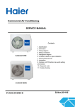
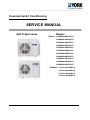
Commercial Air Conditioning
SERVICE MANUAL
MULTI Split series
Models
Indoor: YHKMXH009BARR-FX
YHKMXH012BARR-FX
YHKMXH018BARR-FX
YHKMXH024BARR-FX
YHFMXH012BARR-FX
YHFMXH018BARR-FX
YHFMXH024BARR-FX
YHDMXH009BARR-FX
YHDMXH012BARR-FX
YHDMXH018BARR-FX
YHDMXH024BARR-FX
Outdoor: YJU3YH019BARRA-X
YJU4YH025BARRA-X
YJU4YH030BARRA-X
YJU5YH034BARRA-X
___________________________________________________________________________________
CONTENTS
Contents……………………………………………………….....2
1. Description of products & features………………………….3
2. Specification…………………………………………………...6
3. Dimensions…………………………………………………....21
4. Pipe and wiring installation…..……………………………....26
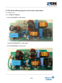
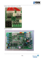
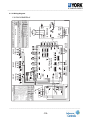
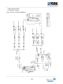
5. PCB photo, wiring diagram and function description……..72
6. Diagnostic code and troubleshooting.……………………...95
7. Outdoor performance curves………..……………………....101
8. Indoor air velocity and temperature distribution curves......105
9. Air flow and static pressure chart…………………………...111
10. Noise level…………………………………………………...113
11. Sensor characteristic….………………………………….....121
12. Controller functions…...………………………………….....124
___________________________________________________________________________________
___________________________________________________________________________________
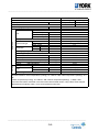
1.Description of products & features
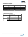
1.1. Brief Introduction for T1,T2,T3 working condition
Climate type
Type
of
Conditioner
Air
T1
T2
T3
Cooling Only
18 ℃~43℃
10℃~35℃
21℃~52℃
Heat pump
-7℃~43℃
-7℃~35℃
-7℃~52℃
Electricity Heating
~43℃
~35℃
~52℃
1.2 Operating Range of Air Conditioners
Working temperature range
Cooling
Indoor
outdoor
Heating
Indoor
outdoor
Rated
Maximum
Minimum
DB℃
27
32
18
WB℃
19
23
14
DB℃
35
43
-10
WB℃
24
26
6
DB℃
20
27
15
WB℃
14.5
--
--
DB℃
7
24
-15
WB℃
6
18
--
___________________________________________________________________________________
___________________________________________________________________________________
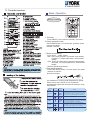
1.3 Product features
DC inverter technology, high energy efficiency, higher EER A+, energy saving for the
user
The outdoor unit adopts DC inverter compressor and motor, so save power energy is just to save
money for the user. And the outdoor can match with multiple indoor units, up to 5 sets. Even when
you have already installed the air conditioner, if you want to add or reduce one unit, go ahead freely
as long as your operation complies with our design. Greatly convenient for designer and installer.
Precise control, more comfortable and more reliable
The outdoor is equipped with electronic expansion valve, which will control refrigerant flow more
precisely. As a result, the user will feel more comfortable and the unit is more reliable.
Also, the outdoor is with oil segregator, which will keep the compressor working normally and make
oil return more smoothly.
Adopt the much friendlier refrigerant R410a
The air conditioner system adopts the greatly friendly refrigerant R410a, which is protective for the
ozone layer and is good to avoid the earth getting warmer. Benefit for the environment.
High voltage communication, convenient wiring work
Connect indoor and outdoor directly, and there is no communication wire between indoors. Thus
the wiring work is more convenient. No need to set indoor address.
Multiple control types
The indoor unit can be controlled by multiple types: infrared controller, wired controller, central
controller. More choice, more conveniently.
10℃ constant temperature control
’
When leave home temporarily, press 10℃ button of remote controller, the indoor temperature won
t decrease rapidly while be controlled at 10℃. When come back home, press it again, the unit will
be back to normal status and setting temperature.
Self-diagnostic function
In the course of operation, if the failure occurs, the failure code will display on the wired controller or
___________________________________________________________________________________
___________________________________________________________________________________
on the operation panel. Then according to the failure code chart, you can eliminate the failure soon.
Central control function, if connected with a central controller
That is convenient for building management.
Weekly timing function, if connected with a weekly timer
Universal power supply for 50Hz and 60Hz
The multi upgrade series adopts universal power supply for 50Hz and 60Hz, which is convenient for
design. Much wider application.
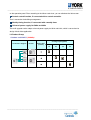
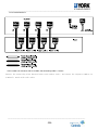
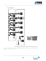
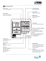
1.4 Product lineup
¾Outdoor unit 220V/1/ (50/60Hz)
Connection diagram
Picture
Max.indoor
quantity
Cooling capacity(Kbtu)
19
25
30
34
3
4
5
___________________________________________________________________________________
___________________________________________________________________________________
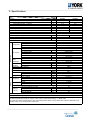
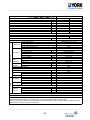
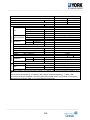
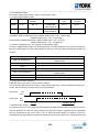
2. Specifications
Item
Model
YJU3YH019BAR-A-X
Piping
Outdoor unit
Function
Cooling
Heating
Rating capacity
W
5400
6500
Power input (indoor + outdoor)
W
1410
1520
Current input (indoor + outdoor)
A
6.13
6.6
EER / COP
W/W
3.84
4.28
Minimum capacity
W
1500
1800
Minimum power input
W
500
500
Maximum capacity
W
7000
8100
Maximum power input (indoor + outdoor)
W
2600
2600
1PH, 220-230V~, 50/60Hz
Power source
Max.Running current (indoor + outdoor)
A/A
11.3
11.3
Power facor(under rating power input)
99%
99%
Fuse size (recommended size)
16
A
Indoor units number
1~3
Model / Manufacture
SNB130FGYMC-L1 / MGC
Oil charge and type
500CC, FV 50S
Compressor
Type
Twin Rotary (DC inverter)
0.58
Ω
Winding resistance(at 20℃)
Axial × 1
Fan type × Number
Max. 860
Motor speed
r/min
Fan motor model
ARW4403AS
Fan system
Motor type
DC
55/69
Motor output/input power
W
about 2000
Air-flows (H/M/L)
m³/h
TP2M / 7.94
Type / Diameter
mm
Heat
Number of rows
2
exchanger
about 0.52
Face area
m²
886/289/688
Dimension
External
mm
(WxDxH)
990/405/760
Package
mm
Refrigerant control method
PMVs
Defrosting method
Automatic by reversible cycle
Crankcase heater power
35
W
52/-/dB(A)
sound pressure(H/M/L)
Noise level
63/-/dB(A)
sound power (H/M/L)
51/ 53
Weight
Net / Shipping
kg / kg
R410A /1.9
Type / Charge
kg
Refrigerant
30
No need to recharge total liquid piping length
m
20
Recharge
g/m
3* Φ6.35
Liquid
mm
Pipe size
3* Φ9.52
Gas
mm
Connecting method
Flared
15
Max.Drop between IU & OU
m
7.5
Between
Max.Drop between indoor units
m
IU & OU
25
Max.Piping length between IU & OU
m
50
Max.Total length
m
1. The above performance data are from the combination of 3U19FS1ERA+3*AS09CS1ERA
2. Large drop and long piping installation will obviously reduce the total capacity.
Norminal condition: indoor temperature (cooling): 27℃DB/19℃WB, indoor temperature (heating): 20℃DB
Outdoor temperature(cooling): 35℃DB/24℃WB, outdoor temperature(heating): 7 ℃DB/6℃WB
The noise level will be measured in the third octave band limited values, using a Real Time Analyser calibrated sound
intensity meter. It is a sound pressure noise level.
___________________________________________________________________________________
___________________________________________________________________________________
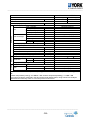
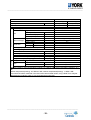
Piping
Outdoor unit
Item
Model
YJU4YH025BAR-A-X
Function
Cooling
Heating
Rating capacity
W
7600
8600
Power input (indoor + outdoor)
W
2100
2060
Current input (indoor + outdoor)
A
9.1
9.0
EER / COP
W/W
3.62
4.18
Minimum capacity
W
1500
1800
Minimum power input
W
550
550
Maximum capacity
W
9000
9500
Maximum power input (indoor + outdoor)
W
3500
3500
Power source
1PH, 220-230V~, 50/60Hz
Max.Running current (indoor + outdoor)
A/A
15.2
15.2
Power facor(under rating power input)
99%
99%
Fuse size (recommended size)
25
A
Indoor units number
2~4
TNB220FLHMC-L / MGC
Model / Manufacture
870CC / FV50S
Oil charge and type
Compressor
Type
Twin Rotary (DC inverter)
0.88
Ω
Winding resistance(at 20℃)
Axial × 1
Fan type × Number
Max. 860
Motor speed
r/min
Fan motor model
EHDS80A100AS
Fan system
Motor type
DC
100/125
Motor output/input power
W
about 4000
Air-flows (H/M/L)
m³/h
TP2M / 7.94
Type / Diameter
mm
Heat
Number of rows
2
exchanger
about 0.75
Face area
m²
948/340/840
Dimension
External
mm
(WxDxH)
1040/430/1000
Package
mm
Refrigerant control method
PMVs
Defrosting method
Automatic by reversible cycle
Crankcase heater power
35
W
56
dB(A)
sound pressure(H/M/L)
Noise level
67
dB(A)
sound power (H/M/L)
74/85
Weight
Net / Shipping
kg / kg
R410A / 3.1
Type / Charge
kg
Refrigerant
40
No need to recharge total liquid piping length
m
20
Recharge
g/m
4* Φ6.35
Liquid
mm
Pipe size
3* Φ9.52(A,B,C)+1*Φ12.7(D)
Gas
mm
Flared
Connecting method
15
Max.Drop between IU & OU
m
7.5
Between
Max.Drop between indoor units
m
IU & OU
25
Max.Piping length between IU & OU
m
70
Max.Total length
m
1. The above performance data are from the combination of 4U25HS1ERA+4*AS09CS1ERA.
2. Large drop and long piping installation will obviously reduce the total capacity.
Norminal condition: indoor temperature (cooling): 27℃DB/19℃WB, indoor temperature (heating): 20℃DB
Outdoor temperature(cooling): 35℃DB/24℃WB, outdoor temperature(heating): 7 ℃DB/6℃WB
The noise level will be measured in the third octave band limited values, using a Real Time Analyser calibrated sound
intensity meter. It is a sound pressure noise level.
___________________________________________________________________________________
-7-
___________________________________________________________________________________
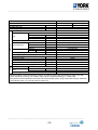
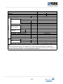
Piping
Outdoor unit
YJU4YH030BAR-A-X
Item
Model
Function
Cooling
Heating
Rating capacity
W
8100
9800
Power input (indoor + outdoor)
W
2220
2430
Current input (indoor + outdoor)
A
9.7
10.6
EER / COP
W/W
3.65
4.03
Minimum capacity
W
1500
1800
Minimum power input
W
550
550
Maximum capacity
W
9800
10500
Maximum power input (indoor + outdoor)
W
3800
3800
Power source
1PH, 220-230V~, 50/60Hz
Max.Running current (indoor + outdoor)
A/A
16.5
16.5
Power facor(under rating power input)
99%
99%
Fuse size (recommended size)
25
A
Indoor units number
2~4
Model / Manufacture
TNB220FLHMC-L / MGC
Oil charge and type
870CC / FV50S
Compressor
Type
Twin Rotary (DC inverter)
0.88
Ω
Winding resistance(at 20℃)
Fan type × Number
Axial × 1
Max. 860
Motor speed
r/min
Fan motor model
EHDS80A100AS
Fan system
Motor type
DC
100/125
Motor output/input power
W
about 4000
Air-flows (H/M/L)
m³/h
TP2M / 7.0
Type / Diameter
mm
Heat
Number of rows
3
exchanger
about 0.75
Face area
m²
948/340/840
Dimension
External
mm
(WxDxH)
1040/430/1000
Package
mm
Refrigerant control method
PMVs
Defrosting method
Automatic by reversible cycle
Crankcase heater power
35
W
58
dB(A)
sound pressure(H/M/L)
Noise level
69
dB(A)
sound power (H/M/L)
76/87
Weight
Net / Shipping
kg / kg
R410A / 3.0
Type / Charge
kg
Refrigerant
40
No need to recharge total liquid piping length
m
20
Recharge
g/m
4* Φ6.35
Liquid
mm
Pipe size
3* Φ9.52(A,B,C)+1*Φ12.7(D)
Gas
mm
Connecting method
Flared
15
Max.Drop between IU & OU
m
7.5
Between
Max.Drop between indoor units
m
IU & OU
25
Max.Piping length between IU & OU
m
70
Max.Total length
m
1. The above performance data are from the combination of 4U30HS1ERA+4*AS09CS1ERA.
2. Large drop and long piping installation will obviously reduce the total capacity.
Norminal condition: indoor temperature (cooling): 27℃DB/19℃WB, indoor temperature (heating): 20℃DB
Outdoor temperature(cooling): 35℃DB/24℃WB, outdoor temperature(heating): 7 ℃DB/6℃WB
The noise level will be measured in the third octave band limited values, using a Real Time Analyser calibrated sound
intensity meter. It is a sound pressure noise level.
___________________________________________________________________________________
-8-
___________________________________________________________________________________
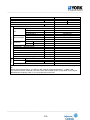
Item
Model
YJU5YH034BAR-A-X
Piping
Outdoor unit
Function
Cooling
Heating
Rating capacity
W
10000
10700
Power input (indoor + outdoor)
W
2940
2850
Current input (indoor + outdoor)
A
12.8
12.4
EER / COP
W/W
3.4
3.75
Minimum capacity
W
1500
1800
Minimum power input
W
550
550
Maximum capacity
W
11000
11500
Maximum power input (indoor + outdoor)
W
4000
4000
1PH, 220-230V~, 50/60Hz
Power source
Max.Running current (indoor + outdoor)
A/A
17.4
17.4
Power facor(under rating power input)
99%
99%
Fuse size (recommended size)
30
A
2~5
Indoor units number
TNB220FLHMC-L / MGC
Model / Manufacture
870CC / FV50S
Oil charge and type
Compressor
Twin Rotary (DC inverter)
Type
0.88
Ω
Winding resistance(at 20 ℃)
Fan type × Number
Axial × 1
Max. 900
Motor speed
r/min
EHDS80A100AS
Fan motor model
Fan system
DC
Motor type
100/125
Motor output/input power
W
about 4000
Air-flows (H/M/L)
m³/h
TP2M / 7.0
Type / Diameter
mm
Heat
Number of rows
3
exchanger
about 0.75
Face area
m²
948/340/840
Dimension
External
mm
(WxDxH)
1040/430/1000
Package
mm
Refrigerant control method
PMVs
Defrosting method
Automatic by reversible cycle
Crankcase heater power
35
W
58/-/dB(A)
sound pressure(H/M/L)
Noise level
69/-/dB(A)
sound power (H/M/L)
77/88
Weight
Net / Shipping
kg / kg
R410A / 3.2
Type / Charge
kg
Refrigerant
40
No need to recharge total liquid piping length
m
20
Recharge
g/m
5* Φ6.35
Liquid
mm
Pipe size
4* Φ9.52(A,B,C,D)+1*Φ12.7(E)
Gas
mm
Flared
Connecting method
15
Max.Drop between IU & OU
m
7.5
Between
Max.Drop between indoor units
m
IU & OU
25
Max.Piping length between IU & OU
m
80
Max.Total length
m
1. The above performance data are from the combination of 5U34HS1ERA+3*AS09CS1ERA+1*AS18CS1ERA.
2. Large drop and long piping installation will obviously reduce the total capacity.
Norminal condition: indoor temperature (cooling): 27 ℃DB/19℃WB, indoor temperature (heating): 20 ℃DB
Outdoor temperature(cooling): 35℃DB/24℃WB, outdoor temperature(heating): 7 ℃DB/6℃WB
The noise level will be measured in the third octave band limited values, using a Real Time Analyser calibrated sound
intensity meter. It is a sound pressure noise level.
___________________________________________________________________________________
-9-
56
___________________________________________________________________________________
Item
Function
Capacity
Sensible heat ratio
Dehumidifying capacity
Power Supply
Model
PIPING
Panel
Indoor unit
YHKMXH009BARR-FX
cooling
heating
kW
2.6
2.9
0.71
/
1.5
10‐³×m³/h
1PH,220-230V 50-60HZ
CENTRIFUGALX1
Type × Number
Speed(H-M-L)
690/620/560
r/min
Fan
Fan motor output power
0.03
kW
Air-flow(H-M-L)
620/520/450
m³/h
Type / Diameter
inner grooved pipe/φ7
mm
Heat exchanger Total Area
0.272
m²
Temp. scope
2-7
℃
570×570×260
External (L×W×H)
mm×mm×mm
Dimension
718×680×380
Package (L×W×H)
mm×mm×mm
Drainage pipe (material , I.D./O.D.)
PVC 26/32
mm
Control type (Remote /wired)
Remote or Wired
Fresh air hole dimension
95
mm
Electricity Heater
NONE
kW
40/36/32
Noise level ---sound presure
(H-M-L)
dB(A)
Noise level ---sound power
(H-M-L)
51/47/43
dB(A)
Weight
(Net / Shipping)
17/20
kg / kg
Panel model (color)
PB-700IB(WHITE)
700×700×60
External
(L×W×H) mm×mm×mm
Dimension
740×750×115
Package
(L×W×H) mm×mm×mm
Weight (Net / Shipping)
kg / kg
2.8 / 4.8
Type
R410A
Refrigerant
Liquid
φ6.35(1/4)
mm
Pipe
Gas
φ9.52(3/8)
mm
Connecting Method
flared
Norminal condition: indoor temperature (cooling): 27℃DB/19℃WB, indoor temperature (heating): 20℃
DB
Outdoor temperature(cooling): 35℃DB/24℃WB, outdoor temperature(heating): 7℃DB/6℃WB
The noise level will be measured in the third octave band limited values, using a Real Time Analyser
calibrated sound intensity meter. It is a sound pressure noise level.
___________________________________________________________________________________
-10-
___________________________________________________________________________________
Item
Function
Capacity
Sensible heat ratio
Dehumidifying capacity
Power Supply
Fan
Model
kW
10‐³×m³/h
Type × Number
Speed(H-M-L)
Fan motor output power
Air-flow(H-M-L)
PIPING
Indoor unit
Static pressure
Type / Diameter
Total Area
Heat exchanger
Temp. scope
External (L×W×H)
Dimension
Package (L×W×H)
Drainage pipe (material , I.D./O.D.)
Control type (Remote / Wired)
Fresh air hole dimension
Electricity Heater
Noise level ---sound presure
(H-M-L)
Noise level ---sound power
(H-M-L)
Weight
(Net / Shipping)
Type
Refrigerant
Liquid
Pipe
Gas
Connecting Method
r/min
kW
m³/h
Pa
mm
m²
℃
mm×mm×mm
mm×mm×mm
mm
mm
kW
dB(A)
dB(A)
kg / kg
mm
mm
YHDMXH009BARR-FX
heating
2.9
/
1.6
1PH,220-230V 50-60HZ
CENTRIFUGALX1
1000/900/800±50
0.05
550/450/400
25
inner grooved pipe/φ7
0.11
2-7
610×483×220
695×536×265
20/18
wired
NONE
NONE
37/34/31
48/45/42
14/16
R410A
φ6.35(1/4)
φ9.52(3/8)
flared
cooling
2.6
0.71
Norminal condition: indoor temperature (cooling): 27℃DB/19℃WB, indoor temperature (heating): 20℃DB
Outdoor temperature(cooling): 35℃DB/24℃WB, outdoor temperature(heating): 7℃DB/6℃WB
The noise level will be measured in the third octave band limited values, using a Real Time Analyser calibrated
sound intensity meter. It is a sound pressure noise level.
___________________________________________________________________________________
-11-
___________________________________________________________________________________
PIPING
Panel
Indoor unit
Item
Model
YHKMXH012BARR-FX
Function
cooling
heating
Capacity
kW
3.5(0.9--4.5)
3.7(1.0--4.8)
Sensible heat ratio
0.71
/
Dehumidifying capacity
1.5
10‐³×m³/h
Power Supply
1PH,220-230V 50-60HZ
Type × Number
CENTRIFUGALX1
Speed(H-M-L)
690/620/560
r/min
Fan
Fan motor output power
0.03
kW
Air-flow(H-M-L)
620/520/450
m³/h
Type / Diameter
inner grooved pipe/φ7
mm
Heat exchanger Total Area
0.272
m²
Temp. scope
2-7
℃
570×570×260
External (L×W×H)
mm×mm×mm
Dimension
718×680×380
Package (L×W×H)
mm×mm×mm
Drainage pipe (material , I.D./O.D.)
PVC 26/32
mm
Control type (Remote /wired)
Remote,.YR-HD
Fresh air hole dimension
56
mm
Electricity Heater
NONE
kW
Noise level ---sound presure
(H-M-L)
40/36/32
dB(A)
Noise level ---sound power
(H-M-L)
51/47/43
dB(A)
Weight
(Net / Shipping)
18.5/23
kg / kg
Panel model (color)
PB-700IB(WHITE)
700×700×60
External
(L×W×H) mm×mm×mm
Dimension
740×750×115
Package
(L×W×H) mm×mm×mm
Weight (Net / Shipping)
kg / kg
3.5/4.5
Type
R410A
Refrigerant
Liquid
φ6.35(1/4)
mm
Pipe
Gas
φ9.52(3/8)
mm
Connecting Method
flared
Norminal condition: indoor temperature (cooling): 27℃DB/19℃WB, indoor temperature (heating): 20℃
DB
Outdoor temperature(cooling): 35℃DB/24℃WB, outdoor temperature(heating): 7℃DB/6℃WB
The noise level will be measured in the third octave band limited values, using a Real Time Analyser
calibrated sound intensity meter. It is a sound pressure noise level.
___________________________________________________________________________________
-12-
___________________________________________________________________________________
PIPING
Indoor unit
Item
Model
YHFMXH012BARR-FX
Function
cooling
heating
Capacity
kW
3.5(0.9--4.5)
3.9(1.0--4.8)
Sensible heat ratio
0.71
/
Dehumidifying capacity
1.6
10‐³×m³/h
Power Supply
1PH,220-230V 50-60HZ
Type × Number
CENTRIFUGALX2
Speed(H-M-L)
1100/1025/825
r/min
Fan
Fan motor output power
0.09
kW
Air-flow(H-M-L)
650/550/450
m³/h
Type / Diameter
inner grooved pipe/φ7
mm
Heat exchanger Total Area
0.20
m²
Temp. scope
2-7
℃
990*655*199
External (L×W×H)
mm×mm×mm
Dimension
1150*750*300
Package (L×W×H)
mm×mm×mm
Drainage pipe (material , I.D./O.D.)
PVC 18/20
mm
Control type (Remote /wired)
Remote,.YR-HD
Fresh air hole dimension
NONE
mm
Electricity Heater
NONE
kW
Noise level ---sound presure
(H-M-L)
41/37/33
dB(A)
Noise level ---sound power
(H-M-L)
52/48/44
dB(A)
Weight
(Net / Shipping)
26.3/32.3
kg / kg
Type
R410A
Refrigerant
Liquid
φ6.35(1/4)
mm
Pipe
Gas
φ9.52(3/8)
mm
Connecting Method
flared
Norminal condition: indoor temperature (cooling): 27℃DB/19℃WB, indoor temperature (heating): 20℃
DB
Outdoor temperature(cooling): 35℃DB/24℃WB, outdoor temperature(heating): 7℃DB/6℃WB
The noise level will be measured in the third octave band limited values, using a Real Time Analyser
calibrated sound intensity meter. It is a sound pressure noise level.
___________________________________________________________________________________
-13-
___________________________________________________________________________________
Item
Function
Capacity
Sensible heat ratio
Dehumidifying capacity
Power Supply
Indoor unit
kW
10‐³×m³/h
Type × Number
Speed(H-M-L)
Fan motor output powe
Air-flow(H-M-L)
r/min
kW
m³/h
Static pressure
Pa
Type / Diameter
mm
Total Area
Heat exchanger
m²
Temp. scope
℃
External (L×W×H) mm×mm×mm
Dimension
Package (L×W×H) mm×mm×mm
Drainage pipe (material , I.D./O.D.)
mm
Control type (Remote / Wired)
Fresh air hole dimension
mm
Electricity Heater
kW
Noise level ---sound presure
(H-M-L)
dB(A)
Noise level ---sound power
(H-M-L)
dB(A)
Weight
(Net / Shipping)
kg / kg
Type
Refrigerant
Liquid
mm
Pipe
Gas
mm
Connecting Method
Fan
PIPING
Model
YHDMXH012BARR-FX
cooling
heating
3.5(0.9--4.5)
4.0(1.0--4.8)
0.71
/
1.6
1PH,220-230V 50-60HZ
CENTRIFUGALX1
1000/900/800±50
0.05
550/450/400
25
inner grooved pipe/φ7
0.11
2-7
610×483×220
695×536×265
20/24
wired,YR-E14
NONE
NONE
37/34/31
48/45/42
14/16
R410A
φ6.35(1/4)
φ9.52(3/8)
flared
Norminal condition: indoor temperature (cooling): 27℃DB/19℃WB, indoor temperature (heating): 20℃
DB
Outdoor temperature(cooling): 35℃DB/24℃WB, outdoor temperature(heating): 7℃DB/6℃WB
The noise level will be measured in the third octave band limited values, using a Real Time Analyser
calibrated sound intensity meter. It is a sound pressure noise level.
___________________________________________________________________________________
-14-
___________________________________________________________________________________
PIPING
Panel
Indoor unit
YHKMXH018BARR-FX
Item
Model
Function
cooling
heating
Capacity
kW
5.0(1.8--5.8)
5.2(2.0--6.5)
Sensible heat ratio
0.71
/
Dehumidifying capacity
1.8
10‐³×m³/h
Power Supply
1PH,220-230V 50-60HZ
Type × Number
CENTRIFUGALX1
Speed(H-M-L)
795/690/550±50
r/min
Fan
Fan motor output power
0.065
kW
Air-flow(H-M-L)
680/620/500
m³/h
Type / Diameter
inner grooved pipe/φ7
mm
Heat exchanger Total Area
0.272
m²
Temp. scope
2-7
℃
570/570/260
External (L×W×H)
mm×mm×mm
Dimension
718*680*380
Package (L×W×H)
mm×mm×mm
Drainage pipe (material , I.D./O.D.)
PVC 26/32
mm
Control type (Remote /wired)
Remote,.YR-HD
Fresh air hole dimension
56
mm
Noise level ---sound presure
(H-M-L)
42/37/35
dB(A)
Noise level ---sound power
(H-M-L)
53/48/46
dB(A)
Weight
(Net / Shipping)
18.5/23
kg / kg
Panel model (color)
PB-700IB(WHITE)
700*700*60
External
(L×W×H) mm×mm×mm
Dimension
740*750*115
Package
(L×W×H) mm×mm×mm
Weight (Net / Shipping)
kg / kg
3.5/4.5
Type
R410A
Refrigerant
Liquid
6.35
mm
Pipe
Gas
12.7
mm
Connecting Method
flared
Norminal condition: indoor temperature (cooling): 27℃DB/19℃WB, indoor temperature (heating): 20℃
DB
Outdoor temperature(cooling): 35℃DB/24℃WB, outdoor temperature(heating): 7℃DB/6℃WB
The noise level will be measured in the third octave band limited values, using a Real Time Analyser
calibrated sound intensity meter. It is a sound pressure noise level.
___________________________________________________________________________________
-15-
___________________________________________________________________________________
PIPING
Indoor unit
Item
Model
YHFMXH018BARR-FX
Function
cooling
heating
Capacity
kW
5.0(1.8--5.8)
5.5(2.0--6.5)
Sensible heat ratio
0.71
/
Dehumidifying capacity
1.8
10‐³×m³/h
Power Supply
1PH,220-230V 50-60HZ
Type × Number
CENTRIFUGALX2
Speed(H-M-L)
1220/1190/1050
r/min
Fan
Fan motor output power
0.075
kW
Air-flow(H-M-L)
800/720/650
m³/h
Type / Diameter
inner grooved pipe/φ7
mm
Heat exchanger Total Area
0.45
m²
Temp. scope
2-7
℃
990*655*199
External (L×W×H)
mm×mm×mm
Dimension
1150*750*300
Package (L×W×H)
mm×mm×mm
Drainage pipe (material , I.D./O.D.)
PVC 18/20
mm
Control type (Remote /wired)
Remote,.YR-HD
Fresh air hole dimension
NONE
mm
Electricity Heater
NONE
kW
Noise level ---sound presure
(H-M-L)
44/41/36
dB(A)
Noise level ---sound power
(H-M-L)
55/52/47
dB(A)
Weight
(Net / Shipping)
28.3/34.3
kg / kg
Type
R410A
Refrigerant
Liquid
φ6.35
mm
Pipe
Gas
φ9.52
mm
Connecting Method
flared
Norminal condition: indoor temperature (cooling): 27℃DB/19℃WB, indoor temperature (heating): 20℃
DB
Outdoor temperature(cooling): 35℃DB/24℃WB, outdoor temperature(heating): 7℃DB/6℃WB
The noise level will be measured in the third octave band limited values, using a Real Time Analyser
calibrated sound intensity meter. It is a sound pressure noise level.
___________________________________________________________________________________
-16-
___________________________________________________________________________________
Item
Function
Capacity
Sensible heat ratio
Dehumidifying capacity
Power Supply
Model
PIPING
Indoor unit
YHDMXH018BARR-FX
cooling
heating
kW
5.0(1.8--6.0)
5.5(2.0--6.2)
0.73
/
2.1
10‐³×m³/h
1PH,220-230V 50-60HZ
Type × Number
CENTRIFUGALX2
730±30/540±30/400±30
Speed(H-M-L)
r/min
Fan
Fan motor output pow
0.05
kW
Air-flow(H-M-L)
850/780/600
m³/h
Static pressure
25
Pa
Type / Diameter
inner grooved pipe/φ7
mm
Heat exchanger
Total Area
0.34
m²
Temp. scope
2-7
℃
1090*500*220
External (L×W×H)mm×mm×mm
Dimension
1174*549*294
Package (L×W×H)mm×mm×mm
Drainage pipe (material , I.D./O.D.)
20/24
mm
Control type (Remote / Wired)
wired,YR-E14
Noise level ---sound presure
(H-M-L)
41/35/32
dB(A)
Noise level ---sound power
(H-M-L)
52/46/43
dB(A)
Weight
(Net / Shipping)
23/26.5
kg / kg
Type
R410A
Refrigerant
Liquid
φ6.35
mm
Pipe
Gas
φ12.7
mm
Connecting Method
flared
Norminal condition: indoor temperature (cooling): 27℃DB/19℃WB, indoor temperature (heating): 20℃
DB
Outdoor temperature(cooling): 35℃DB/24℃WB, outdoor temperature(heating): 7℃DB/6℃WB
The noise level will be measured in the third octave band limited values, using a Real Time Analyser
calibrated sound intensity meter. It is a sound pressure noise level.
___________________________________________________________________________________
-17-
___________________________________________________________________________________
PIPING
Panel
Indoor unit
Item
Model
YHKMXH024BARR-FX
Function
cooling
heating
Capacity
kW
6.5(2.0--7.3)
7.1(2.5--8.0)
Sensible heat ratio
0.72
/
Dehumidifying capacity
2.5
10‐³×m³/h
Power Supply
1PH,220-230V 50-60HZ
Type × Number
CENTRIFUGALX1
Speed(H-M-L)
670±40/550±50/460±50
r/min
Fan
Fan motor output power
0.16
kW
Air-flow(H-M-L)
1300/1100/870
m³/h
Type / Diameter
inner grooved pipe/φ7
mm
Heat exchanger Total Area
0.49
m²
Temp. scope
2-7
℃
840*840*240
External (L×W×H)
mm×mm×mm
Dimension
910*910*300
Package (L×W×H)
mm×mm×mm
Drainage pipe (material , I.D./O.D.)
PVC 26/32
mm
Control type (Remote /wired)
Remote,.YR-HD
Fresh air hole dimension
none
mm
Noise level ---sound presure
(H-M-L)
46/43/36
dB(A)
Noise level ---sound power
(H-M-L)
57/54/48
dB(A)
Weight
(Net / Shipping)
26.8/32.6
kg / kg
Panel model (color)
PB-950JB(WHITE)
950/950/80
External
(L×W×H) mm×mm×mm
Dimension
985/985/115
Package
(L×W×H) mm×mm×mm
Weight (Net / Shipping)
kg / kg
6.0/9.0
Type
R410A
Refrigerant
Liquid
9.52
mm
Pipe
Gas
15.88
mm
Connecting Method
flared
Norminal condition: indoor temperature (cooling): 27℃DB/19℃WB, indoor temperature (heating): 20℃
DB
Outdoor temperature(cooling): 35℃DB/24℃WB, outdoor temperature(heating): 7℃DB/6℃WB
The noise level will be measured in the third octave band limited values, using a Real Time Analyser
calibrated sound intensity meter. It is a sound pressure noise level.
___________________________________________________________________________________
-18-
___________________________________________________________________________________
PIPING
Indoor unit
Item
Model
YHFMXH024BARR-FX
Function
cooling
heating
Capacity
kW
6.3(2.0--7.3)
7.1(2.5--8.0)
Sensible heat ratio
0.72
/
Dehumidifying capacity
2.0
10‐³×m³/h
Power Supply
1PH,220-230V 50-60HZ
Type × Number
CENTRIFUGALX2
Speed(H-M-L)
1220±40/1190±50/1050±50/980±50
r/min
Fan
Fan motor output power
0.10
kW
Air-flow(H-M-L)
800/720/650
m³/h
Type / Diameter
inner grooved pipe/φ7
mm
Heat exchanger Total Area
0.49
m²
Temp. scope
2-7
℃
990*655*199
External (L×W×H)
mm×mm×mm
Dimension
1150*750*300
Package (L×W×H)
mm×mm×mm
Drainage pipe (material , I.D./O.D.)
PVC 18/20
mm
Control type (Remote /wired)
Remote,.YR-HD
Noise level ---sound presure
(H-M-L)
48/46/44
dB(A)
Noise level ---sound power
(H-M-L)
59/57/55
dB(A)
Weight
(Net / Shipping)
28.3/34.3
kg / kg
Type
R410A
Refrigerant
Liquid
9.52
mm
Pipe
Gas
15.88
mm
Connecting Method
flared
Norminal condition: indoor temperature (cooling): 27℃DB/19℃WB, indoor temperature (heating): 20℃
DB
Outdoor temperature(cooling): 35℃DB/24℃WB, outdoor temperature(heating): 7℃DB/6℃WB
The noise level will be measured in the third octave band limited values, using a Real Time Analyser
calibrated sound intensity meter. It is a sound pressure noise level.
___________________________________________________________________________________
-19-
___________________________________________________________________________________
Item
Function
Capacity
Sensible heat ratio
Dehumidifying capacity
Power Supply
Fan
Model
kW
10‐³×m³/h
Type × Number
Speed(H-M-L)
Fan motor output power
Air-flow(H-M-L)
PIPING
Indoor unit
Static pressure
Type / Diameter
Total Area
Temp. scope
External (L×W×H)
Dimension
Package (L×W×H)
Drainage pipe (material , I.D./O.D.)
Control type (Remote / Wired)
Noise level ---sound presure
(H-M-L)
Noise level ---sound power
(H-M-L)
Weight
(Net / Shipping)
Type
Refrigerant
Liquid
Pipe
Gas
Connecting Method
Heat exchanger
r/min
kW
m³/h
Pa
mm
m²
℃
mm×mm×mm
mm×mm×mm
mm
dB(A)
dB(A)
kg / kg
mm
mm
YHDMXH024BARR-FX
cooling
heating
6.8(2.0--7.6)
7.1(3.0--8.3)
0.72
/
2.2
1PH,220-230V 50-60HZ
CENTRIFUGALX2
1250±40/1130±40/1000±50/850±50
0.05
1200/1050/850(white terminal 0 Pa)
25
inner grooved pipe/φ7
0.51
2-7
1090*500*220
1174*549*294
20/24
wired,YR-E14
49/45/41/37
60/56/52/48
25.2/28.4
R410A
9.52
15.88
flared
Norminal condition: indoor temperature (cooling): 27℃DB/19℃WB, indoor temperature (heating): 20℃DB
Outdoor temperature(cooling): 35℃DB/24℃WB, outdoor temperature(heating): 7℃DB/6℃WB
The noise level will be measured in the third octave band limited values, using a Real Time Analyser
calibrated sound intensity meter. It is a sound pressure noise level.
___________________________________________________________________________________
-20-
___________________________________________________________________________________
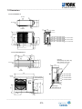
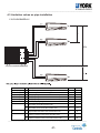
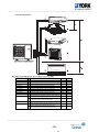
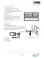
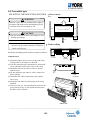
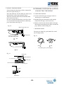
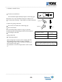
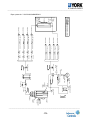
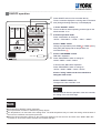
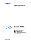
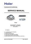
3. Dimension
YJU3YH019BARRA-X
320
Air inlet
353
16.5
Air inlet
52
Air outlet
26
289
Handle
Handle
}
}
}
355
100
24
357
51
688
Liquid pipe:Ø6.35(flared)1/4
A unit connection
Gas pipe :Ø9.52(flared)3/8
Liquid pipe:Ø6.35(flared)1/4
Gas pipe :Ø9.52(flared)3/8 B unit connection
Liquid pipe:Ø6.35(flared)1/4
Gas pipe :Ø9.52(flared)3/8 C unit connection
116
582
146
293
813
73
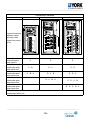
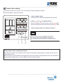
YJU4YH025/30BARRA-X
580
70
340
Air inlet
Gas pipe
Ø9.52(flared) 3/8(A,B,C unit)
Ø12.7(flared) 1/2(D unit)
413
35
Air inlet
184
380
184
35
6
340
Handle
Air outlet
948
A unit connection
B unit connection
D unit connection
537
Liquid pipe
Ø6.35(flared) 1/4
163
315
45
408
C unit connection
50
840
Handle
Indoor and outdoor
connect wiring hole
(30*48)
21
Handle
311
28
___________________________________________________________________________________
-21-
___________________________________________________________________________________
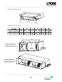
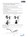
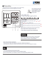
YJU5YH034BARRA-X
580
184
35
340
Air inlet
413
70
35
Air inlet
380
184
Gas pipe
Ø9.52(flared) 3/8(A,B,C,D unit)
Ø12.7(flared) 1/2(E unit)
Air outlet
948
6
Handle
Handle
A unit connection
B unit connection
537
C unit connection
D unit connection
45
408
405
840
Handle
Indoor and outdoor
connect wiring hole
(30*48)
340
311
21
73
E unit connection
28
49
Liquid pipe
Ø6.35(flared) 1/4
___________________________________________________________________________________
-22-
___________________________________________________________________________________
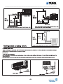
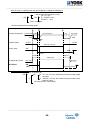
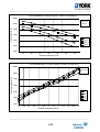
EJZZN[[N \UR[C
:;9
A9
V]NYSJWNM MRZ[JULN KN[^NNU [QN LNRSRUP
JUM [QN WJUNSC ;>TT
:>9TT
@99TT 7WJUNS MRTNUZRVU8
WJUNS
LNRSRUP
56
:A9
><>TT 7KN[^NNU Z\ZWNUZRVU WVSNZ8
OYNZQ JRY QVSN
>@9TT 7RUMVVY \UR[ MRTNUZRVU8
?>9TT 7LNRSRUP VWNURUP MRTNUZRVU8
:=9
@99TT 7WJUNS MRTNUZRVU8
HGFI D
HGFI D
:=> :99 A9
5;:?7<=8697 >:8=4
1-+
1+0
1++
22+
,++
100
/+
.0
.0
.+
-++
-/+
,33
3++
33+
___________________________________________________________________________________
-23-
<;9TT
Z\ZWNUZRVU QVSMNY
@>
>@9TT 7RUMVVY \UR[ MRTNUZRVU8
>@
SRX\RM WRWN
?>
?>9TT 7LNRSRUP VWNURUP MRTNUZRVU8
MYJRUJPN WRWN
PJZ WRWN
?9TT
B9
___________________________________________________________________________________
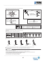
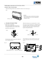
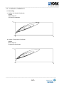
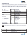
:FJKJMH DNMDFBKFE QSOF RMJQ8
U
Y
T
X
Z
W
[
\
V
=MPQBKKBQJNM EJLFMPJNM8+LL,
YHDMXH009BARR-FX
YHDMXH012BARR-FX
YHDMXH018BARR-FX
YHDMXH024BARR-FX
256
YHDMXH009BARR-FX
YHDMXH012BARR-FX
00.
72.
YHDMXH018BARR-FX
YHDMXH024BARR-FX
00.
___________________________________________________________________________________
-24-
___________________________________________________________________________________
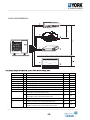
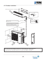
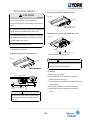
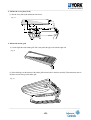
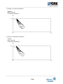
VIEW C
Cassette type unit: 24
VIEW D
740 (hanging position)
860~890 (ceiling hole)
VIEW A
740 (hanging position)
860~890 (ceiling hole)
VIEW B
VIEW D
VIEW C
VIEW B
over 1000
ov
er
ov
er
VIEW A
ov
er
ov
er
___________________________________________________________________________________
-25-
___________________________________________________________________________________
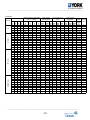
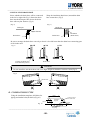
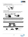
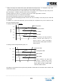
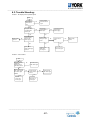
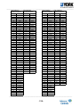
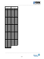
4. Pipe and wiring installation
4.1 Multi combination and the data
YJU3YH019BAR-A-X combination and the data
COOLING
Combinatio
ns
Comb. Uni
t
A
7
9
1x1
12
18
24
7
7
7
7
BI (1x2) 9
9
9
12
12
7
7
7
7
7
TRI (1x3)
7
7
9
9
9
Uni
t
B
—
—
—
—
—
7
9
12
18
9
12
18
12
18
7
7
7
7
9
9
12
9
9
12
Uni
t
C
—
—
—
—
—
—
—
—
—
—
—
—
—
—
7
9
12
18
9
12
12
9
12
12
capacity(Kw)
(Nom. cooling)
total cooling
capacity(kW)
total power input
(kW)
total current
(A)@230V
Unit
A
Unit
B
min. rate max min. rated max.
Unit data d
.
data data Data
C
data data
min.
data
rated
data
2.0
2.5
3.5
5.0
5.4
2.00
2.00
1.96
1.54
2.50
2.25
1.80
2.70
2.22
1.80
1.66
1.44
1.20
1.54
1.35
1.20
1.80
1.59
1.42
—
—
—
—
—
2.00
2.50
3.44
3.86
2.50
3.15
3.60
2.70
3.18
1.80
1.66
1.44
1.20
1.93
1.69
2.10
1.80
1.59
1.99
—
—
—
—
—
—
—
—
—
—
—
—
—
—
1.80
2.08
2.52
3.00
1.93
2.36
2.10
1.80
2.22
1.99
2.22
2.22
2.22
2.22
2.22
2.22
2.22
2.22
2.22
2.22
2.22
2.22
2.22
2.22
2.22
2.22
2.22
2.22
2.22
2.22
2.22
2.22
2.22
2.22
2.44
3.11
4.44
6.65
7.54
5.77
6.65
7.32
7.32
6.88
6.94
7.32
6.94
7.32
7.32
7.32
7.32
7.32
7.10
7.10
7.10
6.25
6.26
6.65
1.0
1.0
1.0
1.5
1.5
1.0
1.0
1.0
1.5
1.0
1.5
1.5
1.5
1.5
1.5
1.5
1.5
1.5
1.5
1.5
1.5
1.5
1.5
1.5
2.0
2.5
3.5
5.0
5.4
4.0
4.5
5.4
5.4
5.0
5.4
5.4
5.4
5.4
5.4
5.4
5.4
5.4
5.4
5.4
5.4
5.4
5.4
5.4
2.8
3.1
4.1
5.4
6.5
4.4
4.9
5.8
7.0
7.0
7.0
7.0
7.0
7.0
7.0
7.0
7.0
7.0
7.0
7.0
7.0
7.0
7.0
7.0
0.5
0.5
0.5
0.5
0.5
0.5
0.5
0.5
0.5
0.5
0.5
0.5
0.5
0.5
0.5
0.5
0.5
0.5
0.5
0.5
0.5
0.5
0.5
0.5
0.6
0.7
1.0
1.5
1.7
1.3
1.5
1.7
1.7
1.6
1.6
1.7
1.6
1.7
1.7
1.7
1.7
1.7
1.6
1.6
1.6
1.4
1.4
1.5
1.3
1.3
1.5
1.9
2.0
2.6
2.6
2.6
2.6
2.6
2.6
2.6
2.6
2.6
2.6
2.6
2.6
2.6
2.6
2.6
2.6
2.6
2.6
2.6
EER
(W/W)
max. rated
Data capacit
y
5.8
3.64
6.0
3.57
6.7
3.50
8.4
3.33
8.9
3.18
12.0
3.08
12.0
3.00
12.0
3.27
12.0
3.27
12.0
3.23
12.0
3.45
12.0
3.27
12.0
3.45
12.0
3.27
12.0
3.27
12.0
3.27
12.0
3.27
12.0
3.27
12.0
3.37
12.0
3.37
12.0
3.38
12.0
3.84
12.0
3.83
12.0
3.60
energy
label
A
A
A
A
B
B
B
A
A
A
A
A
A
A
A
A
A
A
A
A
A
A
A
A
HEATING
Combinatio
ns
Comb. Uni Uni Uni
t
t
t
A B C
7 — —
9 — —
1x1
12 — —
18 — —
24 — —
7 7 —
7 9 —
7 12 —
7 18 —
BI (1x2) 9 9 —
9 12 —
9 18 —
12 12 —
12 18 —
7 7 7
7 7 9
7 7 12
7 7 18
7 9 9
TRI (1x3)
7 9 12
7 12 12
9 9 9
9 9 12
9 12 12
Rated
capacity(kW)
Unit
A
Unit
B
Unit
C
2.3
2.9
3.8
5.5
6.5
2.30
2.30
2.30
1.92
2.90
2.81
2.24
3.25
2.66
2.17
1.99
1.78
1.48
1.85
1.66
1.51
2.17
1.96
1.80
—
—
—
—
—
2.30
2.90
3.80
4.58
2.90
3.69
4.26
3.25
3.84
2.17
1.99
1.78
1.48
2.33
2.09
2.49
2.17
1.96
2.35
—
—
—
—
—
—
—
—
—
—
—
—
—
—
2.17
2.51
2.94
3.54
2.33
2.74
2.49
2.17
2.57
2.35
total heating
capacity(KW)
min. rate max
.
data d
data data
1.0 2.3 4.0
1.0 2.9 4.1
1.0 3.8 4.1
1.5 5.5 6.0
1.5 6.5 7.0
1.2 4.6 5.0
1.2 5.2 5.7
1.2 6.1 6.5
1.8 6.5 8.1
1.8 5.8 8.1
1.8 6.5 8.1
1.8 6.5 8.1
1.8 6.5 8.1
1.8 6.5 8.1
1.8 6.5 8.1
1.8 6.5 8.1
1.8 6.5 8.1
1.8 6.5 8.1
1.8 6.5 8.1
1.8 6.5 8.1
1.8 6.5 8.1
1.8 6.5 8.1
1.8 6.5 8.1
1.8 6.5 8.1
total power input
(W)
min. rated max.
data data Data
0.5
0.5
0.5
0.5
0.5
0.5
0.5
0.5
0.5
0.5
0.5
0.5
0.5
0.5
0.5
0.5
0.5
0.5
0.5
0.5
0.5
0.5
0.5
0.5
0.6
0.8
1.1
1.6
1.8
1.4
1.7
1.7
1.7
1.6
1.6
1.7
1.6
1.7
1.6
1.6
1.6
1.7
1.6
1.6
1.6
1.5
1.5
1.6
1.5
1.4
1.5
2.6
2.6
2.3
2.3
2.3
2.6
2.6
2.6
2.6
2.6
2.6
2.6
2.6
2.6
2.6
2.6
2.6
2.6
2.6
2.6
2.6
total current
EER
(A)@230V
(W/W)
energy
min. rated max. rated
label
data data Data capacit
y
2.1
2.66
5.8
3.83
A
2.1
3.55
6.0
3.63
A
2.1
4.88
6.7
3.45
A
2.1
7.10
8.4
3.44
A
2.1
7.99
8.9
3.61
A
2.5
5.99 10.2
3.41
B
2.5
7.32 13.0
3.15
B
2.5
7.32 13.0
3.70
A
2.7
7.32 13.0
3.94
A
2.7
7.10 13.0
3.63
A
2.5
7.13 13.0
4.04
A
2.5
7.32 13.0
3.94
A
2.7
7.13 13.0
4.04
A
2.7
7.32 13.0
3.94
A
2.5
6.88 13.0
4.19
A
2.7
7.10 13.0
4.06
A
2.7
7.10 13.0
4.06
A
2.5
7.32 13.0
3.94
A
2.5
7.10 13.0
4.06
A
2.5
6.88 13.0
4.19
A
2.5
6.88 13.0
4.19
A
2.5
6.73 13.0
4.28
A
2.5
6.74 13.0
4.28
A
2.5
6.88 13.0
4.19
A
___________________________________________________________________________________
-26-
___________________________________________________________________________________
COOLING
Combinations
Comb.
QUADRI(1x4)
TRI (1x3)
BI (1x2)
1x1
Unit
A
7
9
12
18
24
7
7
9
9
12
12
12
18
18
7
7
7
7
7
7
7
7
7
9
9
9
9
12
12
7
7
7
7
7
7
7
7
9
9
Unit
B
—
—
—
—
—
18
24
18
24
12
18
24
18
24
7
7
7
7
9
9
9
12
12
9
9
9
12
12
12
7
7
7
7
7
7
9
9
9
9
Unit
C
—
—
—
—
—
—
—
—
—
—
—
—
—
—
9
12
18
24
9
12
18
12
18
9
12
18
12
12
18
7
7
7
7
9
9
9
9
9
9
Unit
D
—
—
—
—
—
—
—
—
—
—
—
—
—
—
—
—
—
—
—
—
—
—
—
—
—
—
—
—
—
7
9
12
18
9
12
9
12
9
12
Rated capacity Output/kW
(Nom. cooling)
Unit
Unit Unit Unit
A
B
C
D
2.0
—
—
—
2.5
—
—
—
3.5
—
—
—
5.0
—
—
—
6.5
—
—
—
2.00 5.00
—
—
1.79 5.81
—
—
2.50 5.00
—
—
2.11 5.49
—
—
3.50 3.50
—
—
3.13 4.47
—
—
2.66 4.94
—
—
3.80 3.80
—
—
3.30 4.30
—
—
2.00 2.00 2.50
—
2.00 2.00 3.50
—
1.69 1.69 4.22
—
1.45 1.45 4.70
—
2.00 2.50 2.50
—
1.90 2.38 3.33
—
1.60 2.00 4.00
—
1.69 2.96 2.96
—
1.45 2.53 3.62
—
2.50 2.50 2.50
—
2.24 2.24 3.13
—
1.90 1.90 3.80
—
2.00 2.80 2.80
—
2.53 2.53 2.53
—
2.22 2.22 3.17
—
1.90 1.90 1.90 1.90
1.79 1.79 1.79 2.24
1.60 1.60 1.60 2.80
1.38 1.38 1.38 3.45
1.69 1.69 2.11 2.11
1.52 1.52 1.90 2.66
1.60 2.00 2.00 2.00
1.45 1.81 1.81 2.53
1.90 1.90 1.90 1.90
1.73 1.73 1.73 2.42
total cooling
capacity(kW)
max
min. rated
.
data data
data
1.0
2.0 2.8
1.0
2.5 3.1
1.0
3.5 4.1
1.5
5.0 5.4
1.5
6.5 7.4
1.0
7.0 7.4
1.0
7.6 8.5
1.0
7.5 7.9
1.0
7.6 9.0
1.0
7.0 6.8
1.0
7.6 8.4
1.0
7.6 9.0
1.0
7.6 8.6
1.0
7.6 9.0
1.2
6.5 7.1
1.2
7.5 8.1
1.2
7.6 8.8
1.2
7.6 9.0
1.2
7.0 7.1
1.2
7.6 8.6
1.2
7.6 8.8
1.2
7.6 8.6
1.2
7.6 8.8
1.2
7.5 8.1
1.2
7.6 8.6
1.2
7.6 8.8
1.2
7.6 8.6
1.2
7.6 8.5
1.2
7.6 8.5
1.5
7.6 9.0
1.5
7.6 9.0
1.5
7.6 9.0
1.5
7.6 9.0
1.5
7.6 9.0
1.5
7.6 9.0
1.5
7.6 9.0
1.5
7.6 9.0
1.5
7.6 9.0
1.5
7.6 9.0
total power input
(kW)
min. rated max.
data data Data
0.5 0.56 1.3
0.5 0.70 1.3
0.5 1.00 1.5
0.5 1.50 1.9
0.5 2.00 3.0
0.5 2.25 3.5
0.55 2.25 3.5
0.50 2.25 3.5
0.55 2.25 3.5
0.5 2.19 3.5
0.5 2.19 3.5
0.55 2.39 3.5
0.55 2.39 3.5
0.55 2.40 3.5
0.55 2.00 3.5
0.55 2.19 3.5
0.55 2.34 3.5
0.55 2.34 3.5
0.55 2.14 3.5
0.55 2.19 3.5
0.55 2.34 3.5
0.55 2.19 3.5
0.55 2.34 3.5
0.55 2.14 3.5
0.55 2.14 3.5
0.55 2.14 3.5
0.55 2.14 3.5
0.55 2.14 3.5
0.55 2.19 3.5
0.55 2.14 3.5
0.55 2.14 3.5
0.55 2.14 3.5
0.55 2.19 3.5
0.55 2.14 3.5
0.55 2.14 3.5
0.55 2.14 3.5
0.55 2.10 3.5
0.55 2.10 3.5
0.55 2.10 3.5
total current
EER
(A)@230V
(W/W) energy
rated label
min. rated max.
capaci
data data Data
ty
2.22 2.48
5.8
3.57
A
2.22 3.11
6.0
3.57
A
2.22 4.44
6.7
3.50
A
2.22 6.65
8.4
3.33
A
2.22 8.87 13.2 3.25
A
2.15 10.87 16.8 3.11
B
2.50 10.87 16.8 3.38
A
2.15 10.87 16.8 3.33
A
2.50 10.87 16.8 3.38
A
2.15 10.57 16.8 3.20
A
2.15 10.57 16.8 3.47
A
2.50 11.53 16.8 3.18
B
2.50 11.53 16.8 3.18
B
2.50 11.58 16.8 3.17
B
2.50 9.66 16.8 3.25
A
2.50 10.57 16.8 3.43
A
2.50 11.29 16.8 3.25
A
3.50 11.29 16.8 3.25
A
2.50 10.32 16.8 3.28
A
2.50 10.57 16.8 3.48
A
2.50 11.29 16.8 3.25
A
2.50 10.57 16.8 3.47
A
2.50 11.29 16.8 3.25
A
2.50 10.32 16.8 3.51
A
2.50 10.32 16.8 3.56
A
2.50 10.32 16.8 3.56
A
2.50 10.32 16.8 3.56
A
2.50 10.32 16.8 3.56
A
2.50 10.57 16.8 3.47
A
2.85 10.32 16.8 3.56
A
2.85 10.32 16.8 3.56
A
2.85 10.32 16.8 3.56
A
2.85 10.57 16.8 3.47
A
2.85 10.32 16.8 3.56
A
2.85 10.32 16.8 3.56
A
2.85 10.32 16.8 3.56
A
2.85 10.13 16.8 3.62
A
2.85 10.13 16.8 3.62
A
2.85 10.13 16.8 3.62
A
___________________________________________________________________________________
-27-
___________________________________________________________________________________
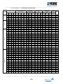
YJU4YH025BARR-A-X
combination and the data
HEATING
Combinations
Comb.
QUADRI(1x4)
TRI (1x3)
TRI (1x2)
1x1
Unit
A
7
9
12
18
24
7
7
9
9
12
12
12
18
18
7
7
7
7
7
7
7
7
7
9
9
9
9
12
12
7
7
7
7
7
7
7
7
9
9
Unit
B
—
—
—
—
—
18
24
18
24
12
18
24
18
24
7
7
7
7
9
9
9
12
12
9
9
9
12
12
12
7
7
7
7
7
7
9
9
9
9
Unit
C
—
—
—
—
—
—
—
—
—
—
—
—
—
Unit
D
—
—
—
—
—
—
—
—
—
—
—
—
—
9
12
18
24
9
12
18
12
18
9
12
18
12
12
18
7
7
7
7
9
9
9
9
9
9
—
—
—
—
—
—
—
—
—
—
—
—
—
—
—
7
9
12
18
9
12
9
12
9
12
Rated capacity Output/kW
(Nom. heating)
Unit
Unit Unit Unit
A
B
C
D
2.3
—
—
—
2.9
—
—
—
3.8
—
—
—
5.5
—
—
—
7.0
—
—
—
2.30 5.50
—
—
2.13 6.47
—
—
2.90 5.50
—
—
2.52 6.08
—
—
3.80 3.80
—
—
3.51 5.09
—
—
3.03 5.57
—
—
4.30 4.30
—
—
3.78 4.82
2.30 2.30 2.90
—
2.30 2.30 3.80
—
1.96 1.96 4.68
—
1.71 1.71 5.19
—
2.30 2.90 2.90
—
2.20 2.77 3.63
—
1.85 2.33 4.42
—
2.00 3.30 3.30
—
1.71 2.82 4.08
—
2.87 2.87 2.87
—
2.60 2.60 3.40
—
2.21 2.21 4.19
—
2.38 3.11 3.11
—
2.87 2.87 2.87
—
2.49 2.49 3.61
—
2.15 2.15 2.15 2.15
2.02 2.02 2.02 2.54
1.85 1.85 1.85 3.05
1.60 1.60 1.60 3.81
1.90 1.90 2.40 2.40
1.75 1.75 2.21 2.89
1.80 2.27 2.27 2.27
1.66 2.10 2.10 2.75
2.15 2.15 2.15 2.15
2.00 2.00 2.00 2.61
total heating
capacity(KW)
max
min. rated
.
data data
data
1.0
2.3 4.0
1.0
2.9 4.1
1.0
3.8 4.1
1.5
5.5 6.0
1.5
7.0 8.6
1.2
7.8 8.4
1.2
8.6 9.5
1.2
8.4 9.2
1.2
8.6 9.5
1.2
7.6 8.2
1.2
8.6 9.5
1.2
8.6 9.5
1.2
8.6 9.5
1.5
8.6 9.5
1.5
7.5 8.4
1.5
8.4 9.3
1.5
8.6 9.5
1.8
8.6 9.5
1.5
8.1 9.5
1.5
8.6 9.5
1.5
8.6 9.5
1.5
8.6 9.5
1.5
8.6 9.5
1.5
8.6 9.5
1.5
8.6 9.5
1.5
8.6 9.5
1.5
8.6 9.5
1.5
8.6 9.5
1.5
8.6 9.5
1.8
8.6 9.5
1.8
8.6 9.5
1.8
8.6 9.5
1.8
8.6 9.5
1.8
8.6 9.5
1.8
8.6 9.5
1.8
8.6 9.5
1.8
8.6 9.5
1.8
8.6 9.5
1.8
8.6 9.5
total power input
(W)
min. rated max.
data data Data
0.55 0.60 1.5
0.55 0.80 1.4
0.55 1.10 1.5
0.55 1.60 2.6
0.55 1.91 2.6
0.50 2.20 3.5
0.55 2.31 3.5
0.50 2.20 3.5
0.55 2.31 3.5
0.50 2.15 3.5
0.50 2.30 3.5
0.55 2.31 3.5
0.55 2.20 3.5
0.55 2.40 3.5
0.55 2.16 3.5
0.55 2.16 3.5
0.55 2.26 3.5
0.55 2.31 3.5
0.55 2.21 3.5
0.55 2.21 3.5
0.55 2.26 3.5
0.55 2.21 3.5
0.55 2.26 3.5
0.55 2.21 3.5
0.55 2.21 3.5
0.55 2.26 3.5
0.55 2.11 3.5
0.55 2.26 3.5
0.55 2.31 3.5
0.55 2.21 3.5
0.55 2.21 3.5
0.55 2.16 3.5
0.55 2.21 3.5
0.55 2.21 3.5
0.55 2.21 3.5
0.55 2.11 3.5
0.55 2.11 3.5
0.55 2.06 3.5
0.55 2.11 3.5
total current
EER
(A)@230V
(W/W) energy
rated label
min. rated max.
capaci
data data Data
ty
2.44 2.66
5.8
3.83
A
2.44 3.55
6.0
3.63
A
2.44 4.88
6.7
3.45
A
2.44 7.10
8.4
3.44
A
2.44 8.47
8.9
3.67
A
2.15 9.76 16.8 3.55
B
2.50 10.24 16.8 3.72
A
2.15 9.76 16.8 3.82
A
2.50 10.24 16.8 3.72
A
2.15 9.54 16.8 3.53
B
2.15 10.20 16.8 3.74
A
2.50 10.24 16.8 3.72
A
2.50 9.76 16.8 3.91
A
2.50 10.65 16.8 3.58
B
2.50 9.58 16.8 3.47
B
2.50 9.58 16.8 3.89
A
2.50 10.02 16.8 3.81
A
2.50 10.24 16.8 3.72
A
2.50 9.80 16.8 3.67
A
2.50 9.80 16.8 3.89
A
2.50 10.02 16.8 3.81
A
2.50 9.80 16.8 3.89
A
2.50 10.02 16.8 3.81
A
2.50 9.80 16.8 3.89
A
2.50 9.80 16.8 3.89
A
2.50 10.02 16.8 3.81
A
2.50 9.36 16.8 4.08
A
2.50 10.02 16.8 3.81
A
2.50 10.24 16.8 3.72
A
2.85 9.80 16.8 3.89
A
2.85 9.80 16.8 3.89
A
2.85 9.58 16.8 3.98
A
2.85 9.80 16.8 3.89
A
2.85 9.80 16.8 3.89
A
2.85 9.80 16.8 3.89
A
2.85 9.36 16.8 4.08
A
2.85 9.36 16.8 4.08
A
2.85 9.13 16.8 4.18
A
2.85 9.36 16.8 4.08
A
___________________________________________________________________________________
-28-
___________________________________________________________________________________
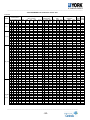
YJU4YH030BARR-A-X
combination and the data
COOLING
Rated capacity Output/kW
(Nom. cooling)
Comb.
Unit Unit Unit Unit Unit Unit Unit Unit
A
B
C
D
A
B
C
D
7
—
—
—
2.0
—
—
—
9
—
—
—
2.5
—
—
—
1x1
12
—
—
—
3.5
—
—
—
18
—
—
—
5.0
—
—
—
24
—
—
—
6.5
—
—
—
7
24
1.91 6.19
9
18
2.50 5.00
9
24
2.25 5.85
12
18
3.16 4.94
12
24
2.67 5.43
18
18
4.05 4.05
18
24
3.52 4.58
24
24
4.05 4.05
7
7
18
1.80 1.80 4.50
24
7
7
1.54 1.54 5.01
7
9
12
2.00 2.50 3.50
7
9
18
1.71 2.13 4.26
24
7
9
1.47 1.84 4.79
7
12
12
1.80 3.15 3.15
7
12
18
1.54 2.70 3.86
24
7
12
1.35 2.36 4.39
9
9
9
2.50 2.50 2.50
9
9
12
2.38 2.38 3.34
9
9
18
2.03 2.03 4.05
24
9
9
1.76 1.76 4.58
9
12
12
2.13 2.98 2.98
9
12
18
1.84 2.58 3.68
24
9
12
1.62 2.27 4.21
12
12
12
2.70 2.70 2.70
12
12
18
2.36 2.36 3.38
12
12
24
2.10 2.10 3.90
12
18
18
2.10 3.00 3.00
7
7
7
7 2.00 2.00 2.00 2.00
7
7
7
9 1.91 1.91 1.91 2.38
7
7
7
12 1.71 1.71 1.71 2.98
7
7
7
18 1.47 1.47 1.47 3.68
24 1.30 1.30 1.30 4.21
7
7
7
7
7
9
9 1.80 1.80 2.25 2.25
7
7
9
12 1.62 1.62 2.03 2.84
7
7
9
18 1.41 1.41 1.76 3.52
7
7
9
24 1.25 1.25 1.56 4.05
7
7
12
12 1.47 1.47 2.58 2.58
7
7
12
18 1.30 1.30 2.27 3.24
7
9
9
9 1.71 2.13 2.13 2.13
7
9
9
12 1.54 1.93 1.93 2.70
7
9
9
18 1.35 1.69 1.69 3.38
7
9
12
12 1.41 1.76 2.47 2.47
7
12
12
12 1.30 2.27 2.27 2.27
9
9
9
9 2.03 2.03 2.03 2.03
9
9
9
12 1.84 1.84 1.84 2.58
9
9
12
12 1.69 1.69 2.36 2.36
9
9
12
18 1.50 1.50 2.10 3.00
9
12
12
12 1.56 2.18 2.18 2.18
12
12
12
12 2.03 2.03 2.03 2.03
QUADRI(1x4)
TRI (1x3)
BI (1x2)
Combinations
total cooling
capacity(kW)
min. rated max.
data data data
1.00 2.00 2.80
1.00 2.50 3.10
1.00 3.50 4.10
1.50 5.00 5.40
1.50 6.50 7.40
1.00 8.10 9.80
1.00 7.50 9.80
1.00 8.10 9.80
1.00 8.10 9.80
1.00 8.10 9.80
1.00 8.10 9.80
1.00 8.10 9.80
1.00 8.10 9.80
1.50 8.10 9.80
1.50 8.10 9.80
1.50 8.00 9.80
1.50 8.10 9.80
1.50 8.10 9.80
1.50 8.10 9.80
1.50 8.10 9.80
1.50 8.10 9.80
1.50 7.50 9.80
1.50 8.10 9.80
1.50 8.10 9.80
1.50 8.10 9.80
1.50 8.10 9.80
1.50 8.10 9.80
1.50 8.10 9.80
1.50 8.10 9.80
1.50 8.10 9.80
1.50 8.10 9.80
1.50 8.10 9.80
1.50 8.00 9.80
1.50 8.10 9.80
1.50 8.10 9.80
1.50 8.10 9.80
1.50 8.10 9.80
1.50 8.10 9.80
1.50 8.10 9.80
1.50 8.10 9.80
1.50 8.10 9.80
1.50 8.10 9.80
1.50 8.10 9.80
1.50 8.10 9.80
1.50 8.10 9.80
1.50 8.10 9.80
1.50 8.10 9.80
1.50 8.10 9.80
1.50 8.10 9.80
1.50 8.10 9.80
1.50 8.10 9.80
1.50 8.10 9.80
1.50 8.10 9.80
1.50 8.10 9.80
total power input
(kW)
min. rated max.
data data Data
0.50 0.56 1.30
0.50 0.70 1.34
0.50 1.00 1.50
0.50 1.50 1.90
0.50 2.00 3.00
0.55 2.60 3.80
0.55 2.40 3.80
0.55 2.50 3.80
0.55 2.40 3.80
0.55 2.50 3.80
0.55 2.40 3.80
0.55 2.50 3.80
0.55 2.60 3.80
0.55 2.40 3.80
0.55 2.50 3.80
0.55 2.30 3.80
0.55 2.40 3.80
0.55 2.50 3.80
0.55 2.40 3.80
0.55 2.40 3.80
0.55 2.50 3.80
0.55 2.30 3.80
0.55 2.35 3.80
0.55 2.40 3.80
0.55 2.50 3.80
0.55 2.40 3.80
0.55 2.40 3.80
0.55 2.50 3.80
0.55 2.40 3.80
0.55 2.40 3.80
0.55 2.45 3.80
0.55 2.50 3.80
0.55 2.25 3.80
0.55 2.25 3.80
0.55 2.25 3.80
0.55 2.40 3.80
0.55 2.50 3.80
0.55 2.25 3.80
0.55 2.25 3.80
0.55 2.40 3.80
0.55 2.45 3.80
0.55 2.25 3.80
0.55 2.40 3.80
0.55 2.25 3.80
0.55 2.28 3.80
0.55 2.40 3.80
0.55 2.30 3.80
0.55 2.30 3.80
0.55 2.22 3.80
0.55 2.25 3.80
0.55 2.25 3.80
0.55 2.30 3.80
0.55 2.35 3.80
0.55 2.35 3.80
total current
(A)@230V
min. rated max.
data data
Data
2.22 2.48
5.80
2.22 3.11
6.00
2.22 4.44
6.70
2.22 6.65
8.40
2.22 8.87 13.20
2.15 11.54 17.90
2.15 10.65 17.90
2.15 11.09 17.90
2.15 10.65 17.90
2.15 11.09 17.90
2.15 10.65 17.90
2.15 11.09 17.90
2.15 11.54 17.90
2.50 10.65 17.90
2.50 11.09 17.90
2.50 10.20 17.90
2.50 10.65 17.90
2.50 11.09 17.90
2.50 10.65 17.90
2.50 10.65 17.90
2.50 11.09 17.90
2.50 10.20 17.90
2.50 10.43 17.90
2.50 10.65 17.90
2.50 11.09 17.90
2.50 10.65 17.90
2.50 10.65 17.90
2.50 11.09 17.90
2.50 10.65 17.90
2.50 10.65 17.90
2.50 10.87 17.90
2.50 11.09 17.90
2.85 9.98 17.90
2.85 9.98 17.90
2.85 9.98 17.90
2.85 10.65 17.90
2.85 11.09 17.90
2.85 9.98 17.90
2.85 9.98 17.90
2.85 10.65 17.90
2.85 10.87 17.90
2.85 9.98 17.90
2.85 10.65 17.90
2.85 9.98 17.90
2.85 10.12 17.90
2.85 10.65 17.90
2.85 10.20 17.90
2.85 10.20 17.90
2.85 9.85 17.90
2.85 9.98 17.90
2.85 9.98 17.90
2.85 10.20 17.90
2.85 10.43 17.90
2.85 10.43 17.90
energy
EER
label
(W/W)
rated
capacity
3.57
A
3.57
A
3.50
A
3.33
A
3.25
A
3.12
B
3.13
B
3.24
A
3.37
A
3.24
A
3.38
A
3.24
A
3.12
B
3.38
A
3.24
A
3.48
A
3.37
A
3.24
A
3.38
A
3.37
A
3.24
A
3.26
A
3.44
A
3.38
A
3.24
A
3.37
A
3.37
A
3.24
A
3.38
A
3.37
A
3.31
A
3.24
A
3.56
A
3.60
A
3.60
A
3.37
A
3.24
A
3.60
A
3.60
A
3.37
A
3.31
A
3.60
A
3.38
A
3.60
A
3.55
A
3.37
A
3.52
A
3.52
A
3.65
A
3.60
A
3.60
A
3.52
A
3.45
A
3.45
A
___________________________________________________________________________________
-29-
___________________________________________________________________________________
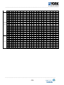
HEATING
Rated capacity Output/kW
(Nom. heating)
Comb.
Unit Unit Unit Unit Unit Unit Unit Unit
A
B
C
D
A
B
C
D
7
—
—
—
2.3
—
—
—
9
—
—
—
2.9
—
—
—
1x1
12
—
—
—
3.8
—
—
—
18
—
—
—
5.5
—
—
—
24
—
—
—
7.0
—
—
—
7
24
2.30 7.00
9
18
2.90 5.50
9
24
2.87 6.93
12
18
3.80 5.50
12
24
3.45 6.35
18
18
4.90 4.90
18
24
4.31 5.49
24
24
4.90 4.90
7
7
18
2.23 2.23 5.34
24
7
7
1.94 1.94 5.91
7
9
12
2.30 2.90 3.80
7
9
18
2.11 2.66 5.04
24
7
9
1.85 2.33 5.62
7
12
12
2.28 3.76 3.76
7
12
18
1.94 3.21 4.65
24
7
12
1.72 2.84 5.24
9
9
9
2.90 2.90 2.90
9
9
12
2.90 2.90 3.80
9
9
18
2.52 2.52 4.77
24
9
9
2.22 2.22 5.36
9
12
12
2.71 3.55 3.55
9
12
18
2.33 3.05 4.42
24
9
12
2.07 2.72 5.01
12
12
12
3.27 3.27 3.27
12
12
18
2.84 2.84 4.11
12
12
24
2.55 2.55 4.70
12
18
18
2.52 3.64 3.64
7
7
7
7 2.30 2.30 2.30 2.30
7
7
7
9 2.30 2.30 2.30 2.90
7
7
7
12 2.11 2.11 2.11 3.48
7
7
7
18 1.82 1.82 1.82 4.35
24 1.62 1.62 1.62 4.94
7
7
7
7
7
9
9 2.17 2.17 2.73 2.73
7
7
9
12 1.99 1.99 2.52 3.30
7
7
9
18 1.73 1.73 2.19 4.15
7
7
12
12 1.85 1.85 3.05 3.05
7
7
12
18 1.62 1.62 2.68 3.88
7
9
9
9 2.05 2.58 2.58 2.58
7
9
9
12 1.89 2.39 2.39 3.13
7
9
9
18 1.66 2.09 2.09 3.96
7
9
12
12 1.76 2.22 2.91 2.91
7
12
12
12 1.65 2.72 2.72 2.72
9
9
9
9 2.45 2.45 2.45 2.45
9
9
9
12 2.27 2.27 2.27 2.98
9
9
12
12 2.12 2.12 2.78 2.78
9
9
12
18 1.88 1.88 2.47 3.57
9
12
12
12 1.99 2.60 2.60 2.60
12
12
12
12 2.45 2.45 2.45 2.45
QUADRI(1x4)
TRI (1x3)
BI (1x2)
Combinations
total heating
capacity(KW)
min. rated max.
data data data
1.00 2.30 4.00
1.00 2.90 4.10
1.00 3.80 4.10
1.50 5.50 6.00
1.50 7.00 8.60
1.20 9.30 10.50
1.20 8.40 10.50
1.20 9.80 10.50
1.20 9.30 10.50
1.20 9.80 10.50
1.20 9.80 10.50
1.20 9.80 10.50
1.20 9.80 10.50
1.20 9.80 10.50
1.50 9.80 10.50
1.50 9.00 10.50
1.50 9.80 10.50
1.50 9.80 10.50
1.50 9.80 10.50
1.50 9.80 10.50
1.50 9.80 10.50
1.50 8.70 10.50
1.50 9.60 10.50
1.50 9.80 10.50
1.50 9.80 10.50
1.50 9.80 10.50
1.50 9.80 10.50
1.50 9.80 10.50
1.50 9.80 10.50
1.50 9.80 10.50
1.50 9.80 10.50
1.50 9.80 10.50
1.50 9.20 10.50
1.50 9.80 10.50
1.80 9.80 10.50
1.80 9.80 10.50
1.80 9.80 10.50
1.80 9.80 10.50
1.80 9.80 10.50
1.80 9.80 10.50
1.80 9.80 10.50
1.80 9.80 10.50
1.80 9.80 10.50
1.80 9.80 10.50
1.80 9.80 10.50
1.80 9.80 10.50
1.80 9.80 10.50
1.80 9.80 10.50
1.80 9.80 10.50
1.80 9.80 10.50
1.80 9.80 10.50
1.80 9.80 10.50
1.80 9.80 10.50
total power input
(W)
min. rated max.
data data Data
0.55 0.60 1.50
0.55 0.80 1.40
0.55 1.10 1.50
0.55 1.60 2.60
0.55 1.80 2.60
0.50 2.60 3.80
0.50 2.60 3.80
0.50 2.70 3.80
0.50 2.60 3.80
0.50 2.70 3.80
0.50 2.60 3.80
0.50 2.70 3.80
0.50 2.75 3.80
0.55 2.60 3.80
0.55 2.70 3.80
0.55 2.60 3.80
0.55 2.60 3.80
0.55 2.70 3.80
0.55 2.70 3.80
0.55 2.60 3.80
0.55 2.70 3.80
0.55 2.20 3.80
0.55 2.70 3.80
0.55 2.43 3.80
0.55 2.70 3.80
0.55 2.70 3.80
0.55 2.60 3.80
0.55 2.70 3.80
0.55 2.58 3.80
0.55 2.60 3.80
0.55 2.65 3.80
0.55 2.75 3.80
0.55 2.38 3.80
0.55 2.70 3.80
0.55 2.60 3.80
0.55 2.60 3.80
0.55 2.70 3.80
0.55 2.60 3.80
0.55 2.60 3.80
0.55 2.60 3.80
0.55 2.60 3.80
0.55 2.60 3.80
0.55 2.60 3.80
0.55 2.60 3.80
0.55 2.70 3.80
0.55 2.50 3.80
0.55 2.50 3.80
0.55 2.43 3.80
0.55 2.50 3.80
0.55 2.50 3.80
0.55 2.55 3.80
0.55 2.60 3.80
0.55 2.60 3.80
total current
(A)@230V
min. rated max.
data data
Data
2.44 2.66
5.80
2.44 3.55
6.00
2.44 4.88
6.70
2.44 7.10
8.40
2.44 7.99
8.90
2.15 11.54 15.00
2.15 11.54 15.00
2.15 11.98 15.00
2.15 11.54 15.00
2.15 11.98 15.00
2.15 11.54 15.00
2.15 11.98 15.00
2.44 12.20 15.00
2.50 11.54 15.00
2.50 11.98 15.00
2.50 11.54 15.00
2.50 11.54 15.00
2.50 11.98 15.00
2.50 11.98 15.00
2.50 11.54 15.00
2.50 11.98 15.00
2.50 9.76 15.00
2.50 11.98 15.00
2.50 10.78 15.00
2.50 11.98 15.00
2.50 11.98 15.00
2.50 11.54 15.00
2.50 11.98 15.00
2.50 11.45 15.00
2.50 11.54 15.00
2.50 11.76 15.00
2.50 12.20 15.00
2.85 10.56 15.00
2.85 11.98 15.00
2.85 11.54 15.00
2.85 11.54 15.00
2.85 11.98 15.00
2.85 11.54 15.00
2.85 11.54 15.00
2.85 11.54 15.00
2.85 11.54 15.00
2.85 11.54 15.00
2.85 11.54 15.00
2.85 11.54 15.00
2.85 11.98 15.00
2.85 11.09 15.00
2.85 11.09 15.00
2.85 10.79 15.00
2.85 11.09 15.00
2.85 11.09 15.00
2.85 11.31 15.00
2.85 11.54 15.00
2.85 11.54 15.00
energy
EER
label
(W/W)
rated
capacity
3.83
A
3.63
A
3.45
A
3.44
A
3.89
A
3.58
B
3.23
C
3.63
A
3.58
B
3.63
A
3.77
A
3.63
A
3.56
B
3.77
A
3.63
A
3.46
B
3.77
A
3.63
A
3.63
A
3.77
A
3.63
A
3.95
A
3.56
B
4.03
A
3.63
A
3.63
A
3.77
A
3.63
A
3.80
A
3.77
A
3.70
A
3.56
B
3.87
A
3.63
A
3.77
A
3.77
A
3.63
A
3.77
A
3.77
A
3.77
A
3.77
A
3.77
A
3.77
A
3.77
A
3.63
A
3.92
A
3.92
A
4.03
A
3.92
A
3.92
A
3.84
A
3.77
A
3.77
A
___________________________________________________________________________________
-30-
___________________________________________________________________________________
YJU5YH034BARR-A-X combination and the data
COOLING
Comb. Uni
t
A
7
9
1x1
12
18
24
7
7
9
9
BI (1x2) 12
12
18
18
24
7
7
7
7
7
7
7
7
7
7
9
TRI (1x3)
9
9
9
9
9
9
12
12
12
12
18
7
7
7
7
7
7
7
7
7
7
QUADR
7
I
7
(1x4)
7
7
7
7
Un
it
B
—
—
—
—
—
18
24
18
24
18
24
18
24
24
7
7
7
9
9
9
9
12
12
12
9
9
9
9
12
12
12
12
12
12
18
18
Unit
C
—
—
—
—
—
—
—
—
—
—
—
—
—
12
18
24
9
12
18
24
12
18
24
9
12
18
24
12
18
24
12
18
24
18
18
7 7
7 7
7 7
7 7
7 7
7 9
7 9
7 9
7 9
7 12
7 12
9 9
9 9
9 9
9 12
12 12
Uni
t
D
—
—
—
—
—
—
—
—
—
—
—
—
—
Uni
t
E
—
—
—
—
—
—
—
—
—
—
—
—
—
—
—
—
—
—
—
—
—
—
—
—
—
—
—
—
—
—
—
—
—
—
—
—
—
—
—
—
—
—
—
—
—
—
—
—
—
—
—
7
9
12
18
24
9
12
18
24
12
18
9
12
18
12
12
—
—
—
—
—
—
—
—
—
—
—
—
—
—
—
—
total cooling
capacity(kW)
Rated capacity Output/kW
(Nom. cooling)
Combinations
Unit
A
2.0
2.5
3.5
5.0
6.5
2.0
2.0
2.5
2.5
3.5
3.5
5.0
4.3
5.0
2.0
2.0
1.9
2.0
2.0
2.0
1.82
2.00
1.90
1.67
2.50
2.50
2.50
2.17
2.50
2.27
2.00
3.33
2.92
2.59
2.59
3.33
2.00
2.00
2.00
1.82
1.60
2.00
2.00
1.74
1.54
1.82
1.60
2.00
1.90
1.67
1.74
1.60
Unit
B
—
—
—
—
—
5.0
6.5
5.0
6.5
5.0
6.5
5.0
5.7
5.0
2.0
2.0
1.9
2.5
2.5
2.5
2.27
3.50
3.33
2.92
2.50
2.50
2.50
2.17
3.50
3.18
2.80
3.33
2.92
2.59
3.70
3.33
2.00
2.00
2.00
1.82
1.60
2.00
2.00
1.74
1.54
1.82
1.60
2.50
2.38
2.08
2.17
2.80
Unit
C
—
—
—
—
—
—
—
—
—
—
—
—
—
Unit
D
—
—
—
—
—
—
—
—
—
—
—
—
—
Unit
E
—
—
—
—
—
—
—
—
—
—
—
—
—
3.50
5.00
6.19
2.50
3.50
5.00
5.91
3.50
4.76
5.42
2.50
3.50
5.00
5.65
3.50
4.55
5.20
3.33
4.17
4.81
3.70
3.33
2.00
2.00
2.00
1.82
1.60
2.50
2.50
2.17
1.92
3.18
2.80
2.50
2.38
2.08
3.04
2.80
—
—
—
—
—
—
—
—
—
—
—
—
—
—
—
—
—
—
—
—
—
—
—
—
—
—
—
—
—
—
—
—
—
—
—
—
—
—
2.0
2.5
3.5
4.5
5.2
2.5
3.5
4.3
5.0
3.2
4.0
2.5
3.33
4.17
3.04
2.8
—
—
—
—
—
—
—
—
—
—
—
—
—
—
—
—
min.
data
1.0
1.0
1.0
1.5
1.5
1.0
1.0
1.0
1.0
1.0
1.0
1.0
1.0
1.0
1.5
1.5
1.5
1.5
1.5
1.5
1.5
1.5
1.5
1.5
1.5
1.5
1.5
1.5
1.5
1.5
1.5
1.5
1.5
1.5
1.5
1.8
1.8
1.8
1.8
1.8
1.8
1.8
1.8
1.8
1.8
1.8
1.8
1.8
1.8
1.8
1.8
1.8
rated
data
2.0
2.5
3.5
5.0
6.5
7.0
8.5
7.5
9.0
8.5
10.0
10.0
10.0
10.0
7.5
9.0
10.0
7.0
8.0
9.5
10.0
9.0
10.0
10.0
7.5
8.5
10.0
10.0
9.5
10.0
10.0
10.0
10.0
10.0
10.0
10.0
8.0
8.5
9.5
10.0
10.0
9.0
10.0
10.0
10.0
10.0
10.0
9.5
10.0
10.0
10.0
10.0
max.
data
2.8
3.1
4.1
5.4
7.4
7.5
9.0
8.0
9.5
9.0
10.5
10.5
10.5
10.5
8.1
9.8
10.5
7.6
8.6
10.2
10.5
9.6
10.5
10.5
8.1
9.1
10.5
10.5
10.2
10.5
10.5
10.5
10.5
11.0
11.0
11.0
8.8
9.3
10.3
11.0
11.0
9.8
10.5
11.0
11.0
10.8
11.0
10.3
10.8
11.0
10.8
11.0
total power input
(kW)
min.
data
0.50
0.50
0.50
0.50
0.50
0.50
0.50
0.50
0.50
0.50
0.50
0.50
0.50
0.50
0.55
0.55
0.55
0.55
0.55
0.55
0.55
0.55
0.55
0.55
0.55
0.55
0.55
0.55
0.55
0.55
0.55
0.55
0.55
0.55
0.55
0.55
0.55
0.55
0.55
0.55
0.55
0.55
0.55
0.55
0.55
0.55
0.55
0.55
0.55
0.55
0.55
0.55
rated
data
0.65
0.80
1.04
1.50
2.00
2.30
2.80
2.40
2.70
2.70
3.10
3.10
3.10
3.20
2.74
2.74
3.04
2.74
2.74
2.90
3.04
3.04
3.04
3.04
3.04
3.04
3.04
3.04
3.04
3.04
3.04
3.04
2.99
3.27
3.27
3.32
2.89
2.89
2.96
2.99
2.99
2.96
2.96
2.99
2.99
2.96
2.99
2.96
2.99
2.99
2.96
2.96
max.
Data
1.3
1.3
1.5
1.9
3.0
4.0
4.0
4.0
4.0
4.0
4.0
4.0
4.0
4.0
4.0
4.0
4.0
4.0
4.0
4.0
4.0
4.0
4.0
4.0
4.0
4.0
4.0
4.0
4.0
4.0
4.0
4.0
4.0
4.0
4.0
4.0
4.0
4.0
4.0
4.0
4.0
4.0
4.0
4.0
4.0
4.0
4.0
4.0
4.0
4.0
4.0
4.0
total current
(A)@230V
min.
data
2.2
2.2
2.2
2.2
2.2
2.15
2.15
2.15
2.15
2.15
2.15
2.15
2.15
2.15
2.5
2.5
2.5
2.5
2.5
2.5
2.5
2.5
2.5
2.5
2.5
2.5
2.5
2.5
2.5
2.5
2.5
2.5
2.5
2.5
2.5
2.5
2.5
2.5
2.5
2.5
2.5
2.5
2.5
2.5
2.5
2.5
2.5
2.5
2.5
2.5
2.5
2.5
rated
data
2.88
3.55
4.61
6.65
8.87
10.20
12.42
10.65
11.98
11.98
13.75
13.75
13.75
14.20
12.16
12.16
13.49
12.16
12.16
12.87
13.49
13.49
13.49
13.49
13.49
13.49
13.49
13.49
13.49
13.49
13.49
13.49
13.27
14.51
14.51
14.73
12.82
12.82
13.13
13.27
13.27
13.13
13.13
13.27
13.27
13.13
13.27
13.13
13.27
13.27
13.13
13.13
EER
(W/W) energ
rated y label
max.
capacit
Data
y
5.8
3.08
B
6.0
3.13
B
6.7
3.37
A
8.4
3.33
A
13.2
3.25
A
19.0
3.04
B
19.0
3.04
B
19.0
3.13
B
19.0
3.33
A
19.0
3.15
B
19.0
3.23
A
19.0
3.23
A
19.0
3.22
A
19.0
3.13
B
19.0
2.74
D
19.0
3.28
A
19.0
3.29
A
19.0
2.55
E
19.0
2.92
C
19.0
3.28
A
19.0
3.29
A
19.0
2.96
C
19.0
3.29
A
19.0
3.29
A
19.0
2.47
E
19.0
2.80
D
19.0
3.29
A
19.0
3.29
A
19.0
3.13
B
19.0
3.29
A
19.0
3.29
A
19.0
3.29
A
19.0
3.34
A
19.0
3.06
B
19.0
3.06
B
19.0
3.01
B
19.0
2.77
D
19.0
2.94
C
19.0
3.21
A
19.0
3.34
A
19.0
3.34
A
19.0
3.04
B
19.0
3.38
A
19.0
3.34
A
19.0
3.34
A
19.0
3.38
A
19.0
3.34
A
19.0
3.21
A
19.0
3.34
A
19.0
3.34
A
19.0
3.38
A
19.0
3.38
A
___________________________________________________________________________________
-31-
___________________________________________________________________________________
(1×5)
9 9 9
9 — 2.50
9 9 9 12 — 2.27
9 9 9 18 — 2.00
9 9 12 12 — 2.08
9 12 12 12 — 1.92
12 12 12 12
2.50
7 7 7
7 7 2.00
7 7 7
7 9 1.90
7 7 7
7 12 1.74
7 7 7
9 9 1.82
7 7 7
9 12 1.67
7 7 7 12 12 1.54
7 7 9
9 9 1.74
7 7 9
9 12 1.60
7 9 9
9 9 1.67
9 9 9
9 9 2.00
9 9 9
9 12 1.85
9 9 9 12 12 1.72
2.50
2.27
2.00
2.08
2.69
2.50
2.00
1.90
1.74
1.82
1.67
1.54
1.74
1.60
2.08
2.00
1.85
1.72
2.50
2.27
2.00
2.92
2.69
2.50
2.00
1.90
1.74
1.82
1.67
1.54
2.17
2.00
2.08
2.00
1.85
1.72
2.5
3.18
4.0
2.92
2.69
2.5
2.0
1.9
1.74
2.27
2.08
2.69
2.17
2.00
2.08
2.00
1.85
2.41
—
—
—
—
—
2.00
2.38
3.04
2.27
2.92
2.69
2.17
2.80
2.08
2.00
2.59
2.41
1.8
1.8
1.8
1.8
1.8
1.8
2.0
2.0
2.0
2.0
2.0
2.0
2.0
2.0
2.0
2.0
2.0
2.0
10.0
10.0
10.0
10.0
10.0
10.0
10.0
10.0
10.0
10.0
10.0
10.0
10.0
10.0
10.0
10.0
10.0
10.0
11.0
11.0
11.0
11.0
11.0
11.0
11.0
11.0
11.0
11.0
11.0
11.0
11.0
11.0
11.0
11.0
11.0
11.0
0.55
0.55
0.55
0.55
0.55
0.55
0.55
0.55
0.55
0.55
0.55
0.55
0.55
0.55
0.55
0.55
0.55
0.55
3.01
2.96
2.94
2.96
2.96
2.97
3.01
2.99
2.97
2.96
2.97
3.01
3.06
3.06
3.09
3.06
3.12
3.12
4.0
4.0
4.0
4.0
4.0
4.0
4.0
4.0
4.0
4.0
4.0
4.0
4.0
4.0
4.0
4.0
4.0
4.0
2.5
2.5
2.5
2.5
2.5
2.5
2.5
2.5
2.5
2.5
2.5
2.5
2.5
2.5
2.5
2.5
2.5
2.5
13.35
13.13
13.04
13.13
13.13
13.18
13.35
13.27
13.18
13.13
13.18
13.35
13.58
13.58
13.71
13.58
13.84
13.84
19.0
19.0
19.0
19.0
19.0
19.0
19.0
19.0
19.0
19.0
19.0
19.0
19.0
19.0
19.0
19.0
19.0
19.0
3.32
3.38
3.40
3.38
3.38
3.37
3.32
3.34
3.37
3.38
3.37
3.32
3.27
3.27
3.24
3.27
3.20
3.20
A
A
A
A
A
A
A
A
A
A
A
A
A
A
A
A
A
A
HEATING
Rated capacity Output/kW
(Nom. heating)
Combinations
Comb. Uni
t
A
7
9
1x1
12
18
24
7
7
9
9
BI (1x2) 12
12
18
18
24
7
7
7
7
7
7
7
7
7
7
9
TRI (1x3)
9
9
9
9
9
9
12
12
12
12
Un
it
B
—
—
—
—
—
18
24
18
24
18
24
18
24
24
7
7
7
9
9
9
9
12
12
12
9
9
9
9
12
12
12
12
12
12
18
Unit
C
—
—
—
—
—
—
—
—
—
—
—
—
—
12
18
24
9
12
18
24
12
18
24
9
12
18
24
12
18
24
12
18
24
18
Uni
t
D
—
—
—
—
—
—
—
—
—
—
—
—
—
Uni
t
E
—
—
—
—
—
—
—
—
—
—
—
—
—
—
—
—
—
—
—
—
—
—
—
—
—
—
—
—
—
—
—
—
—
—
—
—
—
—
—
—
—
—
—
—
—
—
—
—
—
—
—
Unit
A
2.3
2.9
3.8
5.5
7.0
2.30
2.30
2.90
2.90
4.37
3.76
5.35
4.71
5.35
2.30
2.30
2.12
2.30
2.30
2.30
2.02
2.30
2.12
1.88
2.90
2.90
2.75
2.42
2.90
2.54
2.26
3.57
3.10
2.78
2.75
Unit
B
—
—
—
—
—
5.50
7.00
5.50
7.00
6.33
6.94
5.35
5.99
5.35
2.30
2.30
2.12
2.90
2.90
2.90
2.54
3.80
3.51
3.10
2.90
2.90
2.75
2.42
3.80
3.33
2.97
3.57
3.10
2.78
3.98
total heating
capacity(KW)
Unit
C
—
—
—
—
—
—
—
—
—
—
—
—
—
Unit
D
—
—
—
—
—
—
—
—
—
—
—
—
—
Unit
E
—
—
—
—
—
—
—
—
—
—
—
—
—
3.80
5.50
6.46
2.90
3.80
5.50
6.14
3.80
5.07
5.72
2.90
3.80
5.21
5.85
3.80
4.82
5.47
3.57
4.49
5.13
3.98
—
—
—
—
—
—
—
—
—
—
—
—
—
—
—
—
—
—
—
—
—
—
—
—
—
—
—
—
—
—
—
—
—
—
—
—
—
—
min.
data
1.0
1.0
1.0
1.5
1.5
1.2
1.2
1.2
1.2
1.2
1.2
1.2
1.2
1.2
1.5
1.5
1.5
1.5
1.5
1.5
1.5
1.5
1.5
1.5
1.5
1.5
1.5
1.5
1.5
1.5
1.5
1.5
1.5
1.8
1.8
rated
data
2.3
2.9
3.8
5.5
7.0
7.8
9.3
8.4
9.9
10.7
10.7
10.7
10.7
10.7
8.4
10.1
10.7
8.1
9.0
10.7
10.7
9.9
10.7
10.7
8.7
9.6
10.7
10.7
10.5
10.7
10.7
10.7
10.7
10.7
10.7
max.
data
4.0
4.1
4.1
6.0
8.6
7.8
9.3
8.4
9.9
9.3
10.8
11.0
11.5
11.5
8.4
10.1
11.5
8.1
9.0
10.7
11.5
9.9
11.5
11.5
8.7
9.6
11.0
11.5
10.5
11.5
11.5
11.5
11.5
11.5
11.5
total power input
(W)
min.
data
0.50
0.50
0.50
0.55
0.55
0.50
0.50
0.50
0.50
0.50
0.50
0.50
0.50
0.50
0.55
0.55
0.55
0.55
0.55
0.55
0.55
0.55
0.55
0.55
0.55
0.55
0.55
0.55
0.55
0.55
0.55
0.55
0.55
0.55
0.55
rated
data
0.66
0.86
1.16
1.66
2.06
2.20
2.80
2.40
2.70
2.90
2.90
2.90
2.90
3.00
2.51
2.76
2.96
2.51
2.51
2.96
3.01
2.71
3.11
3.01
2.56
2.61
3.01
3.01
3.01
3.01
3.01
3.01
3.01
3.10
3.10
max.
Data
1.50
1.40
1.50
2.60
2.60
4.00
4.00
4.00
4.00
4.00
4.00
4.00
4.00
4.00
4.00
4.0
4.0
4.0
4.0
4.0
4.0
4.0
4.0
4.0
4.0
4.0
4.0
4.0
4.0
4.0
4.0
4.0
4.0
4.0
4.0
total current
(A)@230V
min.
data
2.22
2.22
2.22
2.44
2.44
2.15
2.15
2.15
2.15
2.15
2.15
2.15
2.15
2.44
2.50
2.5
2.5
2.5
2.5
2.5
2.5
2.5
2.5
2.5
2.5
2.5
2.5
2.5
2.5
2.5
2.5
2.5
2.5
2.5
2.5
rated
data
2.93
3.82
5.15
7.36
9.14
9.76
12.42
10.65
11.98
12.87
12.87
12.87
12.87
13.31
11.14
12.24
13.13
11.14
11.14
13.13
13.35
12.02
13.80
13.35
11.36
11.58
13.35
13.35
13.35
13.35
13.35
13.35
13.35
13.75
13.75
EER
(W/W) energ
rated y label
max.
capacit
Data
y
5.8
3.48
A
6.0
3.37
A
6.7
3.28
A
8.4
3.31
A
8.9
3.40
A
19.0
3.55
B
19.0
3.32
C
19.0
3.50
B
19.0
3.67
A
19.0
3.69
A
19.0
3.69
A
19.0
3.69
A
19.0
3.69
A
19.0
3.57
B
19.0
3.35
C
19.0
3.66
A
19.0
3.61
A
19.0
3.23
C
19.0
3.59
B
19.0
3.61
A
19.0
3.55
B
19.0
3.65
A
19.0
3.44
B
19.0
3.55
B
19.0
3.40
C
19.0
3.68
A
19.0
3.55
B
19.0
3.55
B
19.0
3.49
B
19.0
3.55
B
19.0
3.55
B
19.0
3.55
B
19.0
3.55
B
19.0
3.45
B
19.0
3.45
B
___________________________________________________________________________________
-32-
___________________________________________________________________________________
18
7
7
7
7
7
7
7
7
7
7
QUADR
7
I
7
(1x4)
7
7
7
7
9
9
9
9
9
12
7
7
7
7
7
7
(1×5)
7
7
7
9
9
9
18
7
7
7
7
7
7
7
7
7
7
7
9
9
9
9
12
9
9
9
9
12
12
7
7
7
7
7
7
7
7
9
9
9
9
18
7
7
7
7
7
9
9
9
9
12
12
9
9
9
12
12
9
9
9
12
12
12
7
7
7
7
7
7
9
9
9
9
9
9
7
9
12
18
24
9
12
18
24
12
18
9
12
18
12
12
9
12
18
12
12
12
7
7
7
9
9
12
9
9
9
9
9
12
—
—
—
—
—
—
—
—
—
—
—
—
—
—
—
—
—
—
—
—
—
7
9
12
9
12
12
9
12
9
9
12
12
3.57
2.30
2.30
2.30
1.98
1.77
2.30
2.18
1.89
1.70
2.02
1.77
2.24
2.07
1.81
1.92
1.80
2.68
2.48
2.19
2.32
2.17
2.68
2.14
2.03
1.89
1.94
1.81
1.70
1.85
1.73
1.77
2.14
2.01
1.90
3.57
2.30
2.30
2.30
1.98
1.77
2.30
2.18
1.89
1.70
2.02
1.77
2.82
2.61
2.28
2.42
2.97
2.68
2.48
2.19
2.32
2.84
2.68
2.14
2.03
1.89
1.94
1.81
1.70
1.85
1.73
2.23
2.14
2.01
1.90
3.57
2.30
2.30
2.30
1.98
1.77
2.90
2.75
2.39
2.14
3.33
2.93
2.82
2.61
2.28
3.18
2.97
2.68
2.48
2.19
3.03
2.84
2.68
2.14
2.03
1.89
1.94
1.81
1.70
2.33
2.19
2.23
2.14
2.01
1.90
2.30
2.90
3.80
4.75
5.39
2.90
3.60
4.53
5.17
3.33
4.23
2.82
3.42
4.33
3.18
2.97
2.68
3.25
4.14
3.03
2.84
2.68
2.14
2.03
1.89
2.44
2.28
2.80
2.33
2.19
2.23
2.14
2.01
2.49
—
—
—
—
—
—
—
—
—
—
—
—
—
—
—
—
—
—
—
—
—
2.14
2.56
3.13
2.44
2.99
2.80
2.33
2.86
2.23
2.14
2.64
2.49
1.8
1.8
1.8
1.8
1.8
1.8
1.8
1.8
1.8
1.8
1.8
1.8
1.8
1.8
1.8
1.8
1.8
1.8
1.8
1.8
1.8
1.8
1.8
1.8
1.8
1.8
1.8
1.8
1.8
1.8
1.8
1.8
1.8
1.8
1.8
10.7
9.2
9.8
10.7
10.7
10.7
10.4
10.7
10.7
10.7
10.7
10.7
10.7
10.7
10.7
10.7
10.7
10.7
10.7
10.7
10.7
10.7
10.7
10.7
10.7
10.7
10.7
10.7
10.7
10.7
10.7
10.7
10.7
10.7
10.7
11.5
9.2
9.8
10.7
11.5
11.5
10.4
11.5
11.5
11.5
11.5
11.5
11.5
11.5
11.5
11.5
11.5
11.5
11.5
11.5
11.5
11.5
11.5
11.5
11.5
11.5
11.5
11.5
11.5
11.5
11.5
11.5
11.5
11.5
11.5
0.55
0.55
0.55
0.55
0.55
0.55
0.55
0.55
0.55
0.55
0.55
0.55
0.55
0.55
0.55
0.55
0.55
0.55
0.55
0.55
0.55
0.55
0.55
0.55
0.55
0.55
0.55
0.55
0.55
0.55
0.55
0.55
0.55
0.55
0.55
3.15
2.87
2.87
2.87
2.87
2.87
2.87
2.87
2.87
2.87
2.87
2.87
2.87
2.90
2.87
2.87
2.88
2.92
2.87
2.85
2.87
2.87
2.91
2.92
2.91
2.90
2.90
2.89
2.90
2.87
2.91
2.92
2.87
2.92
3.26
4.0
4.0
4.0
4.0
4.0
4.0
4.0
4.0
4.0
4.0
4.0
4.0
4.0
4.0
4.0
4.0
4.0
4.0
4.0
4.0
4.0
4.0
4.0
4.0
4.0
4.0
4.0
4.0
4.0
4.0
4.0
4.0
4.0
4.0
4.0
2.5
2.5
2.5
2.5
2.5
2.5
2.5
2.5
2.5
2.5
2.5
2.5
2.5
2.5
2.5
2.5
2.5
2.5
2.5
2.5
2.5
2.5
2.5
2.5
2.5
2.5
2.5
2.5
2.5
2.5
2.5
2.5
2.5
2.5
2.5
13.98
12.73
12.73
12.73
12.73
12.73
12.73
12.73
12.73
12.73
12.73
12.73
12.73
12.87
12.73
12.73
12.78
12.95
12.73
12.64
12.73
12.73
12.91
12.95
12.91
12.87
12.87
12.82
12.87
12.73
12.91
12.95
12.73
12.95
14.46
19.0
19.0
19.0
19.0
19.0
19.0
19.0
19.0
19.0
19.0
19.0
19.0
19.0
19.0
19.0
19.0
19.0
19.0
19.0
19.0
19.0
19.0
19.0
19.0
19.0
19.0
19.0
19.0
19.0
19.0
19.0
19.0
19.0
19.0
19.0
3.40
3.21
3.41
3.73
3.73
3.73
3.62
3.73
3.73
3.73
3.73
3.73
3.73
3.69
3.73
3.73
3.71
3.66
3.73
3.75
3.73
3.73
3.68
3.66
3.68
3.69
3.69
3.70
3.69
3.73
3.68
3.66
3.73
3.66
3.28
___________________________________________________________________________________
-33-
C
C
B
A
A
A
A
A
A
A
A
A
A
A
A
A
A
A
A
A
A
A
A
A
A
A
A
A
A
A
A
A
A
A
C
___________________________________________________________________________________
4.2. Wiring connection
YJU3YH019BARRA-X
If this outdoor unit connects with AS*S1ERA, the connecting cable is 1.5mm2
Connect the connecting wires between indoor and outdoor units
terminals
and ensure the sequence numbers on
match with each other.
___________________________________________________________________________________
-34-
___________________________________________________________________________________
YJU4YH025/30BARRA-X
If this outdoor unit connects with AS*S1ERA, the connecting cable is 1.5mm2
Connect the connecting wires between indoor and outdoor units
terminals
and ensure the sequence numbers on
match with each other.
___________________________________________________________________________________
-35-
___________________________________________________________________________________
YJU5YH034BARRA-X
If this outdoor unit connects with AS*S1ERA, the connecting cable is 1.5mm2
Connect the connecting wires between indoor and outdoor units
terminals
and ensure the sequence numbers on
match with each other.
___________________________________________________________________________________
-36-
___________________________________________________________________________________
4.3 Limitation values on pipe installation
YJU3YH019BARRA-X
Item
Unit Description
Standard Maximum
A,B,C liquid pipe
mm Size of the liquid side connection pipe
φ6.35
A,B,C Gas pipe
mm Size of the gas side connection pipe
φ9.52
/
L1 (one way)
m
Max.piping length between IU and OU of the way
≤10
≤25
L2 (one way)
m
Max.piping length between IU and OU of the way
≤10
≤25
L3 (one way)
m
Max.piping length between IU and OU of the way
≤10
≤25
L1+L2+L3
m
Total liquid piping length
Drop between every two indoor units when the location of
the outdoor unit is among indoor units
Drop between every two indoor units when the location of
the outdoor unit is at one side of indoor units
≤30
≤50
≤1
≤15
≤1
≤7.5
Drop between the outdoor unit and the indoor unit
≤5
≤15
m
h
m
H+
m
m
Hm
Drop between the outdoor unit and the indoor unit when the
≤5
location of outdoor unit is among the indoor units
Drop between the outdoor unit and the indoor unit when the
≤5
location of outdoor unit is at one side of indoor units
/
≤7.5
≤15
___________________________________________________________________________________
-37-
___________________________________________________________________________________
YJU4YH025/30BARRA-X
Item
Unit Description
Standard Maximum
A,B,C, Dliquid pipe mm Size of the liquid side connection pipe
φ6.35
/
A,B,C Gas pipe
mm Size of the gas side connection pipe
φ9.52
/
D Gas pi[pe
mm Size of the gas side connection pipe
φ12.7
/
L1 (one way)
m
Max.piping length between IU and OU of the way
≤10
≤25
L2 (one way)
m
Max.piping length between IU and OU of the way
≤10
≤25
L3 (one way)
m
Max.piping length between IU and OU of the way
≤10
≤25
L4 (one way)
m
Max.piping length between IU and OU of the way
≤10
≤25
L1+L2+L3+L4
m
Total liquid piping length
Drop between every two indoor units when the location of
the outdoor unit is among indoor units
Drop between every two indoor units when the location of
the outdoor unit is at one side of indoor units
≤40
≤70
≤1
≤15
≤1
≤7.5
Drop between the outdoor unit and the indoor unit
≤5
≤15
m
h
m
H+
m
m
Hm
Drop between the outdoor unit and the indoor unit when the
≤5
location of outdoor unit is among the indoor units
Drop between the outdoor unit and the indoor unit when the
≤5
location of outdoor unit is at one side of indoor units
≤7.5
≤15
___________________________________________________________________________________
-38-
___________________________________________________________________________________
YJU5YH034BARRA-X
Uni
Description
t
A,B,C,D,E liquid pipe mm Size of the liquid side connection pipe
Item
A,B,C,D Gas pipe
Standard Maximum
mm Size of the gas side connection pipe
φ6.35
/
φ9.52
/
E Gas pi[pe
mm Size of the gas side connection pipe
φ12.7
/
L1 (one way)
m
Max.piping length between IU and OU of the way
≤10
≤25
L2 (one way)
m
Max.piping length between IU and OU of the way
≤10
≤25
L3 (one way)
m
Max.piping length between IU and OU of the way
≤10
≤25
L4 (one way)
m
Max.piping length between IU and OU of the way
≤10
≤25
L5 (one way)
m
Max.piping length between IU and OU of the way
≤10
≤25
L1+L2+L3+L4+L5
m
Total liquid piping length
Drop between every two indoor units when the location of
the outdoor unit is among indoor units
Drop between every two indoor units when the location of
the outdoor unit is at one side of indoor units
≤40
≤80
≤1
≤15
≤1
≤7.5
Drop between the outdoor unit and the indoor unit
≤5
≤15
m
h
m
H+
m
m
Hm
Drop between the outdoor unit and the indoor unit when the
≤5
location of outdoor unit is among the indoor units
Drop between the outdoor unit and the indoor unit when the
≤5
location of outdoor unit is at one side of indoor units
≤7.5
≤15
___________________________________________________________________________________
-39-
___________________________________________________________________________________
Connection cautions
model
YJU3YH019BARRA-X
YJU4YH025/30BARRA-X
YJU5YH034BARRA-X
connection priority
between indoor
and stop valve
higher from down
to up
when there is 1
D
indoor,the prior
C
E
stop valve is
when there are 2
D、C
indoors,the prior
E、D
C、B
stop valves are
when there are 3
D、C、B
indoors,the prior
C、B、A
E、D、C
stop valves are
when there are 4
D、C、B、A
indoors,the prior
E、D、C、B
stop valves are
when there are 5
indoors,the prior
E、D、C、B、A
stop valves are
Note: For better oil return and more reliable system, please execute as the above when
connecting indoor unit.
___________________________________________________________________________________
-39-
___________________________________________________________________________________
Installation figure please refers to YJU4YH025BAR-A-X
e
or
M
an
th
More than 5cm
4.4 Outdoor installation
cm
10
Arrangement of piping directions
Rear left
Left
Rear right
Right
Below
Attention must be
paid to the rising
up of drain hose
Wrap the insulation pipe with the finishing tape
from bottom to top.
Cut thermal insulation pipe to an appropriate
length and wrap it with tape, making sure that no
gap is left in the insulation pipe's cut line.
cm
n 10
e tha
mor
mo
re t
han
10c
m
m
0c
n6
tha
e
r
mo
mo
re
tha
n2
5c
m
If there is the danger of the unit falling or overturning, fix the unit with foundation bolts, or with wire or other means.
If the location does not have good drainage, place the unit on a level mounting base(or a plastic pedestal).
Install the outdoor unit in a level position. Failure to do so may result in water leakage or accumulation.
___________________________________________________________________________________
-40-
___________________________________________________________________________________
20
Check the strength and level of the installation ground so that the unit will not cause any operating vibration or noise after installed.
In accordance with the foundation drawing in fix the unit securely by means of the foundation bolts.(Prepare four sets of M8 or M10
foundation bolts, nuts and washers each which are available on the market.)
It is best to screw in the foundation bolts until their length are 20mm from the foundation surface.
Outdoor Unit Installation Guideline
Where a wall or other obstacle is in the path of outdoor unit's intake or exhaust airflow, follow the installation guidelines below.
For any of the below installation pattems, the wall height on the exhaust side should be 1200mm or less.
Wall facing one side
More than 50
More than 300
1200 or
less
Side view
Wall facing two sides
Wall facing three sides
More than 150
More
More
than 100 than 300
More
than 50
More
than 100
More
than 50
Side view
More than 300
Side view
Limitations on the installation
1.Precautions on installation
Check the strength and level of the installation ground so that unit will not cause any operating vibration or noise after installation.
In accordance with the foundation drawing in fix the unit securely by means of the foundation bolts.
It is best to screw in the foundation bolts unit their length are 20 mm from the foundation surface.
2.Selecting a location for installation of the indoor units
The maxinum allowable length of refrigerant piping, and the maxmum allowable height difference between the outdoor and indoor units,
are listed below. (The shorter the refrigerant piping, the better the performance. Connect so that the piping is as short as possible. Shortest
allowable length per room is 3m)
3U19FS1ERA
4U25HS1ERA
4U30HS1ERA
5U34HS1ERA
Piping to each indoor unit
25m max.
25m max.
25m max.
Total length of piping between al lunits
50m max.
70m max.
80m max.
Outdoor unit capacity class
___________________________________________________________________________________
-41-
___________________________________________________________________________________
___________________________________________________________________________________
-42-
___________________________________________________________________________________
3. Refrigerant piping work
1). Align the centres of both flares and tighten the flare nuts 3 or 4 turns by hand. Then tighten them fully with the tor wrenches.
Use torque wrenches when tightening the flare nuts to prevent damage to the flare nuts and escaping gas.
Flare nut fightening torque
Flare nut for
6.35
14.2-17.2N.m(144-175kgf.cm)
Flare nut for
9.52
32.7-39.9N.m(333-407kgf.cm)
Flare nut for
12.7
49.5-60.3N.m(505-615kgf.cm)
Flare nut for
15.88 61.8-75.4N.m(630-769kgf.cm)
Valve cap tightening torque
Liquid pipe 26.5-32.3N.m(270-330kgf.cm)
Coat here with refrigeration oil
Torque spanner
Spanner
Service port cap tightening torque
Pipe joint
10.8-14.7N.m(110-150kgf.cm)
Gas pipe 48.1-59.7N.m(490-610kgf.cm)
Cone nut
2)To prevent gas leakage, apply refrigeration oil on both inner and outer surfaces of the flare. (Use refrigeration oil for R410A)
4. Purging air and checking gas leakage
When piping work is completed, it is necessary to purge the air and check for gas leakage.
WARNING
1) Do not mix any substance other than the specified refrigerant (R410A) into the refrigeration cycle.
2) When refrigerant gas leaks occur, ventilate the room as soon and as much as possible.
3) R410A, as well as other refrigerants, should always be recovered and never be released directly into the environment.
4) Use a vacuum pump for R410A exclusively. Using the same vacuum pump for different refrigerents may damage the vacuun pump
or the unit.
If using additional refrigerant, perform air purging from the refrigerant pipes and indoor unit using a vacuum pump, then charge additional
refrigerant.
Use a hexagonal wrench (4mm) to operate the stop valve rod.
All refrigerant pipe joints should be tightened with a torque wrench at the specified tightening torque.
Connect projection side of charging hose(Which comes from gauge manifold) to gas stop valve's service port.
Fully open gauge manifold's low-pressure valve(Lo) and completely close its high-pressure valve(Hi).
(High-pressure valve subsequently requires no operation.)
Apply vacuum pumping. Check that the compound pressure gauge reads-0.1MPa(-76cmHg).
Evacuation for at lease 1 hour is recommended.
Close gauge manifold's low-pressure valve(Lo) and stop vacuum pump.
(Leave as is for 4-5 minutes and make sure the coupling meter needie does not go back.
If it does go back, this may indicate the presence of moisture or leaking from connecting parts. After inspecting all the connection and
loosening then retightening thenuts, reqeat steps 2-4. )
Remove covers from liquid stop valve and gas stop valve.
Turn the liquid stop valve's rod 90 degrees counterclockwise with a hexagonal wrench to open valve.
Close it after 5 seconds, and check for gas leakage.
Using soapy water, check for gas leakage from indoor unit's flare and outdoor unit's flare and valve rods.
After the check is complete, wipe all soapy water off.
Disconnect charging hose from gas stop valve's service port, then fully open liquid and gas stop valves.
(Do not attempt to turn valve rodj beyond its stop.)
Tighten valve caps and service port caps for the liquid and gas stop valves with a torque wrench at the specified torques. See "3
Refrigerant piping " on page 6 for details.
___________________________________________________________________________________
___________________________________________________________________________________
5. Refilling the refrigerant
Check the type of refrigerant to be used on the machine namiplate.
Precautions when adding R410A
Fill from the liquid pipe in liquid form.
It is a mixed refrigerant, so adding it in gas form may cause the refrigerant composition to change, preventing normal operation.
1) Before filling, check whether the cylinder has a siphon attached or not.(It should have something like "liquid filling siphon attached"
displayed on it.)
Filling a cylinder with an attached siphon
Filling other cylinders
Stand the cylinder upright when filling.
Turn the cylinder upside-down
when filing.
There is a siphon pipe inside, so the
cylinder need not be upside-down
to fill with liquid.
2) Be sure to use the R410A tools to ensure pressure and to prevent foreign objects entering.
6. Charging with refrigerant
1) This system must use refrigersant R410A.
2) Add refrigerant 20g per meter when the total piping length
exceeds the standard value, but make sure that the total liquid
piping length should be less than the max. value.
YJU3YH019BARRA-X
YJU4YH025BARRA-X
YJU4YH030BARRA-X
YJU5YH034BARRA-X
Notes:
1) When using this product, you need not to set the address. But the L/N wires between indoor & outdoor units must be corresponded,
or there will be communication failure.
2) Quiet Operation Setting. Set the DIP "8" to ON position of SW5, the system will run with lower noise, but the max. capacity will also
reduce slightly.
3) Do not change the settings of other switchs, wrong settings can make the system damage or other malfunctions.
7.Precautions for Laying Refrigerant Piping
Cautions on pipe handling
1) Protect the open end of the pipe against dust and moisture.
2) All pipe bends should be as gentle as possible. Use a pipe bender for bending.(Bending radius should be 30 to 40mm or larger.)
Selection of copper and heat insulation materials
When using commercial copper pipes and fittings, observe the following :
1) Insulation material: Polyethylene foam
o
Heat transfer rate: 0.041 to 0.052W/mK(0.035to 0.045kcal/mh C)
o
Refrigerant gas pipe's surface temperature reaches 110 C max.
Choose heat insulation materials that will withstand this temperature.
2) Be sure to insulate both the gas and liquid piping and to provide insulation dimensions as below.
Gas pipe
Gas pipe insulation
O.D.:9.52mm,12.7mm
Thickness:0.8mm
I.D.:12-15mm,12.7mm
Thickness:13mm min.
Liquid pipe
Liquid pipe insulation
O.D.:6.35mm
Thickness:0.8mm
I.D.:18-10mm
Thickness:10mm min.
___________________________________________________________________________________
-44-
___________________________________________________________________________________
3) Use separate thermal insulation pipes for gas and liquid refrigerant
pipe.
Inter unit wiring
Gas pipe
Wall
Be sure to
place a cap.
Liquid pipe
Rain
If no flare cap is
available, cover the
flare mouth with tape
to keep dirt or water
out.
Liquid pipe
insulation
Gas pipe
insulation
Finishing tape
Drain hose
Check
Flare's inner
surface must be
flaw-free.
The pipe end
must be evenly
flared in a perfect
circle.
Cut exactly at right
angles.
Remove burrs
Make sure that the
flare nut is fitted.
Set exactly at the position shown below.
A
Flare tool for R410A
Flare tooling die
Conventional flare tool
Clutch-type
Clutch-type(Rigid-type)
Wing-nuttype(Imperial-type)
0-0.5mm
1.0-1.5mm
1.5-2.0mm
8.Cutting and Flaring work of piping
Pipe cutting is carried out with a pipe cutter and burs must be
removed.
After inserting the flare nut, flaring work is carried out.
A
Flare tooling die
Pipe
Pipe diameter
Liquid side
Gas side
Correct
Size A (mm)
6.35mm(1/4")
0.8~1.5
9.52mm(3/8")
1.0~1.5
12.7mm(1/2")
1.0~1.5
Incorrect
Lean Damage of flare Crack
Partial
Too outside
9. On drainage
Please install the drain hose so as to be downward slope without fail. Please don't do the drainage as shown below.
Less than
5cm
It becomes high
midway.
The end is immersed
in water
It waves.
It gap with the ground its
too small.
There is the bad
smell from a ditch.
Please pour water in the drain pan of the indoor unit, and confirm that drainage is carried out serely to outdoor.
In case that the attached drain hose is in a room, please apply heat insulation to it without fail.
WARNING
1) Do not use mineral oil on flared part.
2) Prevent mineral oil from getting into the system as this would educe the lifetime of the units.
3) Never use piping which has been used for previous installations. Only use parts which are delivered with the unit.
4) Do never install a drier to this R410A unit in order to guarantee its lifetime.
5) The drying material may dissolve and damage the system.
6) Incom;ete flaring may cause refrigerant gas leakage.
___________________________________________________________________________________
-45-
___________________________________________________________________________________
In order to protect the environment, be sure to pump down when relocating or disposing of the unit.
1) Remove the valve caps from liquid stop valve and gas stop valve.
2) Carry out forced cooling operation.
3) After five to ten minutes, close the liquid stop valve with a hexagonal wrench.
4) After two to three minutes, close the gas stop vaile and stop forced cooling
operation.
liquid
stop valve
Hexagonal
wernch
Close
Gas
stop valve
Valve cap
1. Electric wiring
The air conditioner must use special circuit , and wiring by the qualified electrician according to the wiring rules specified in national
standard.
The grounding wire and the neutral wire shall be strictly separated. Connect the neutral wire with grounding wire is incorrect.
The electric leakage breaker must be installed.
All the electric wire must be copper wire.Power supply: 1PH, 220-230V~, 50/60Hz.
The wiring method of power line is Y connection. If the power line is damaged, in order to avoid risk of electric shock, it must be replaced
by the manufacturer or its repair center or other similar qualified person.The connecting cable must be shielded.
Fuse: T3.15A 250VAC T16A 250VAC (Please check with the outdoor unit wiring diagram.)
Please check the circuit diagram about the fuse replaced.
2. Wiring method
Wiring method of orbicular terminals
For the connection wire with orbicular terminals, its wiring method is as shown in
the right figure: remove the connecting screw, put the screw through the ring on
the end of the wire, then connect to the terminal block and fasten screw.
Wiring method of straight terminals.
For the connection wire without orbicular terminals, its wiring method is: loosen
the connection screw, and insert the end of the connection wire completely into
the Terminal block, then fasten the screw.
Slightly pull the wire outwards to confirm it is firmly held.
Wiring Method for
Ring Terminal Block
Crimp connection method for wires without terminals
Connect the wire with
same diameter to the
two sides of the terminal
Do not connect the
wire with same diameter
to the same side
Wrong Pressing
Correct Pressing
Do not connect the
wire with different
diameters
Terminal
block
Pressing
Clamps
Crimp connection method for connection wire
After connection,the wire must be fastened by wire cover. The wire cover shall press on the protection
coat of the connection wire,as shown in right top figure.
Note:When connecting the wiring,confirm the terminal number of indoor and outdoor units carefully.
Incorrect wiring will damage the controller of air conditioner or the unit can not operate.
3. Wiring method of outdoor unit:
Power line
Remove the repair board of the outdoor unit and loosen the wire cover A,then put the live wire, neutral wire and grounding wire through
the wire cover ,and connect them to terminal block correspon dingly. After connection, fasten wire cover to its previous state.
Communication wire of indoor unit.
Loosen wire cover , put the communication wire through the wire cover B, and connect them to terminal block correspondingly. After
connection, fasten wire cover B to its previous state.
Note: Power line and communication wire are provided by consumers themselves.
___________________________________________________________________________________
-46-
___________________________________________________________________________________
Wire cover A
Wire cover A Wire cover C Terminal block
Wire cover C
Wire cover B
Wire cover B
Terminal block
Valve cover
–¨
25.40
Wire cover D
Wire cover E
Valve cover
0
4. Wiring method of indoor unit
Loosen wire cover and connect the power line and communication wire of indoor unit to the terminal correspondingly.
Note:
When connecting power line to power supply terminal, please pay attention to the following items:
Do not connect the power line with different dimensions to the same connection wire end.
Improper contact will cause heat generation.
Do not connect the power line with different dimensions to the same grounding wire end.
Improper contact will affect protection.
Do not connect the power line to the connecting end of communication wire.
Incorrect connection will cause damage to the connected unit.
5. Example wiring diagram.
Wiring diagram please refers toYJU4YH025BARRA-X
YCZ-A001
YCZ-A003
___________________________________________________________________________________
-47-
___________________________________________________________________________________
Before starting the test running, please confirm the following works have been done successfully.
1) Correct piping work;
2) Correct wiring work;
3) Correct match of indoor and outdoor unit;
4) Proper recharge of refrigerant if needed.
Make sure that all the stop valves are fully open.
Check the voltage supplied to the outdoor and indoor units, please cinfirm that is 230V.
Wiring Error Check
This product is capable of automatic checking of wiring error.
CN2
Switch on all the 4 dip-switches on the outdoor unit small service PC-board as shown on the right. Then power
off the unit and power on again, the system will enter the operation of "Wiring Error Check". After 3 minutes
stand-by, the unit starts for automatic wiring checking.
Approximately 30 ~ 50minutes (depends on how many units installed in the system) after the unit starts, the
Errors of the wiring will be shown by the LEDs (1 to 5).
CN3
SW1
ON
CN4
1234
CN1
1
2
3
4
5
During this operation, the digital-number will alternately show the compressor working frequency (e.g. 50 stands for the current running
frequency) and letter "CH"(means checking).
After this operation, if all the wiring is correct, the digital-number will show "0", if there has wrong wiring, the digital-number will show "EC"(error
connection) and also it will flashing.
The service monitor LEDs indicate the error of wiring, as shown in the table below. For details about how to read the LED display, refer to
the service manual.
If self-checking is not possible, check the indoor unit wiring and piping in the usual manner.
Status
Test running.
1) If the temperature is lower than 16 OC, it is impossible to test cooling with remote controller, and also when the temperature is higher than
30 OC, it is impossible to test heating.
2) To test cooling, set the lowest temperature at 16 OC. To test heating,set the highest temperature, at 30 OC.
3) Please check both cooling and heating operation of each unit individually and then also check the simultaneous operation of all indoor
units.
4) After ruuning the unit for about 20 minutes, check the indoor unit outlet temperature.
5) After the unit is stopped, or working mode changed, the system will not start again for about 3 minutes.
6) During cooling operation, frost may ocur on the indoor unit or pipes, this is normal.
7) Operate the unit according to the operation manual. Please kindly explain to our customers how to operate through the instruction manual.
Seven-segment numeric display
1) When unit is runing, this seven-segment numeric will display the frequency of compressor. For
example,
means compressor running frequency is 40 Hz,
means compressor running
frequency is 108Hz.
2) When faulty happens, seven-segment numeric will flash and display some numbers, this number is
failure code. For example, a flashing
means No.32 failure, that is indoor and outdoor communication
error.
CN2
CN3
SW1
ON
CN4
1234
CN1
1
2
3
4
5
Communication LED
5 green LED means 5 indoor units. If one LED keep lighting that means the corresponding indoor unit has good communication with outdoor
unit. If one LED is not lighting, that means there is no communication between indoor and outdoor.
___________________________________________________________________________________
-48-
___________________________________________________________________________________
4.5. Cassette type
Vilmaggamfji ^jjgl
30Jjop]hh]pekj pkkho
Uda ejop]hh]pekj pkkho heopa` ej pda
bkhhksejc odaap _]j ^a qoa` ]o namqena`0
30 T_nas `neran
40 I]_go]s
,8- Qh]_a opnkjc ajkqcd pk oqllknp pda qjep saecdp0
,9- Ok atlajoera ]npe_hao oq_d ]o pahareoekj ]j` le]jk ^ahks
ej`kkn qjep0
,:- Fjkqcd ol]_a bkn i]ejpaj]j_a0
,;- Qh]_a ikna pd]j 3i ]s]u bnki pahareoekj ]j` n]`ek pk ]rke`
`eopqn^ejc pahareoekj ]j` n]`ek0
,32- F]ou bkn i]ejpaj]j_a0
I
60 Jjjan dat]ckj ol]jjan.odebpejc
ol]jjan
2053i
50 Enehh sepd ] `e]iapan kb 82ii
70 Tl]jjan ,36. 39. 3;.46.49ii80 Qela _qppan
Ben kqphap
90 Qela atl]j`an
307i
:0 Ljeba
330 C]j` p]la
340 T_n]lan
307i
407i Pran
40Jjop]hh]pekj Qnal]n]pekj
,3- Qkoepekj kb _aehejc klajejc ^apsaaj qjep ]j` oqolaj`ejc
^khp ,bnkjp reas kb qjep-0
Q]npo O]ia
B
B`daoera p]la
C
Qela _h]il
D
Dkjja_pejc dkoa
E
En]ej]ca dkoa
F
Okj/du`nko_kle_
da]p ejoqh]pejc i]pane]h
Jj`kkn qjep 792ii
Daehejc klajejc 872ii
Pnj]iajp l]jah 922ii
Pranh]l ^apsaaj _aehejc ]j`
knj]iajp l]jah od]hh ^a 47ii
Tqolaj`ejc ^khpo
Vilmaggamfji [kjbdcnkdl
30Taha_pekj kb Jjop]hh]pekj Qh]_a
,3- Qh]_a ]^kra pda _aehejc sdana d]ra ajkqcd
ol]_a pk ]nn]jca pda qjep0
,4- Qh]_a sdana pda `n]ej]ca lela _]j ^a
]nn]jca` sahh0
,5- Qh]_a sdana ejhap ]j` kqphap ]en kb ej`kkn
]j` kqp`kkn qjep sehh jkp ^a ^hk_ga`0
,6- Ek jkp atlkoa pda qjep pk pda lh]_a sepd
da]ru keh kn ikeopqna ,a0c0gep_daj ]j`
skngodkl-0
,7- Ek jkp oap pda qjep ej pda lh]_a sdana
`aopnq_pera c]o ,oq_d ]o oqhbqne_ ]_e` c]o- kn
lqjcajp c]o ,pdejjan ]j` c]okheja_kj_ajpn]pao ]j` nap]ejo0
372ii
Huloqi lks`an
Daehejc
Pnj]iajp l]jah
542ii
G
Eeop]j_a ^apsaaj
oqolaj`ejc ^khpo 757ii
82ii
Tui^kh
Jj`kkn qjep 792ii
350 Sabnecan]jp keh
40B__aookneao , b]_pknu lnkre`a` -
Pnj]iajp l]jah 922ii
320 Ma]g]ca `apa_pkn kn ok]lu s]pan
Ben kqphap
Daehejc klajejc 872ii
;0 Qej_ano
Ben ejhap
,4- Qnal]na ]hh lelejc ,nabnecan]jp.s]pan `n]ej]ca -]j` senao
,_kjja_pekj sena kb naikpa _kjpnkhhan. ej`kkn qjep _kjja_pekj
senao- pk pda ej`kkn qjep ^abkna ejop]hh]pekj ej kn`an pk _kjja_p
ej`kkn qjep eiia`e]pahu ]bpan ejop]hh]pekj0
Vilmaggamfji [kjbdcnkdl
,5- Jjop]hh ] oqolaj`ejc ^khp
Uk oqllknp pda qjep saecdp .]j_dkn ^khp odkqh` ^a qoa` ej pda
_]oa kb ]hna]`u ateopo _aehejc0 Gks jas _aehejc. qoa bhqod/ej pula
^khp. ^qehp/ej pula ^khp kn l]npo lnap]na` ej pda beah`0
Cabkna ckejc kj ejop]hhejc. ]`fqop ol]_a pk _aehejc0
___________________________________________________________________________________
-49-
___________________________________________________________________________________
Skkb
>Jjop]hh]pekj Ft]ilha@
72 w372ii
Bj_dkn ^khp
Mkjc jqp kn pdna]`
Tqolaj`ejc ^ehp N32
Daehejc
Okpa< Bhh pda ]^kra iajpekja` l]npo od]hh ^a lnal]na` ej baeh`.
pda `e]iapan kb oqolaj`ejc ^khp eo N32
50 Jjop]hh]pekj kb ej`kkn qjep
Jj _]oa kb jk _aehejc
Jjop]hh qjep pailkn]nehu
Qqp oqolaj`ejc ^n]_gap kj pda oqolaj`ejc ^khp pk d]jc pda qjep ql0 Ca oqna pk qoa jqp ]j` s]odan ]p ^kpd
aj` kb pda ^na]gap pk oa_qna benihu0
Bbpan ejop]hh]pekj kj pda _aehejc
,3- B`fqop qjep pk epo necdp lkoepekj ,Saban pk lnal]n]pekj bkn ejop]hh]pekj/,3-,4-Dda_g pd]p qjep eo dknevkjp]h0
X]pan lqil ]j` bhk]pejc osep_d eo ejop]hha` ejoe`a ej`kkn qjep._da_g bkqn _knjano kb pda qjep bkn epo haran
qoejc dknevkjp]h _kil]n]pkn kn QWD pq^a sepd s]pan0,Jb qjep eo pehpejc ]c]ejop pda `ena_pekj kb s]pan `n]ej]ca.
lnk^hai i]u k__qn kj bhk]pejc s]pan ha]g]ca0Oqp ,Qnal]na ej baeh`X]odan ,Qnal]na` ej baeh`-
Jj pda _]oa kb _aehejc ]hna]`u ateopo
,3-Jjop]hh qjep pailkn]nehu
Qqp oqolaj`ejc ^n]_gap kj pda oqolaj`ejc ^khp pk d]jc pda
qjep ql0Ca oqna pk qoa jqp ]j` s]odan ]p ^kpd aj` kb pda
^n]_gap pk oa_qna ep benihu0
,4-B`fqop pda daecdp ]j` lkoepekj kb pda qjep0
,5-Qnk_aa` sepd lnk_a`qna ,6- kb + Jj pda _]oa kb jk _aehejc +
Tqolaj`ejc ^khpo
G]opaj ,`kq^ha jqpo-
Jjoanp
harahan
X]odan betejc l]`
,lnal]na` ej baeh`[ oa_qna pda s]odan benihu\
Qkhupdaja lela
60 Jjop]hh]pekj kb s]pan `n]ej]ca lela
,3- Jjop]hh s]pan `n]ej]ca lela
Qela `e]iapan od]hh ^a amq]h kn h]ncan pd]j pd]p kb _kjja_pejc lela ,Qela kb lkhupdaja= oeva<47ii= P0E0< 54ii En]ejlela odkqh` ^a odknp. sepd ] `ksjs]n` ohkla ]p ha]op 31322 pk lnarajp ]en ^]c bnki bkniejc0
Jb `ksjs]n` ohkla kb `n]ejlela _]jjkp ^a i]`a.hebpejc lela od]hh ^a ejop]hha`0
Laal ] `eop]j_a kb 3/307i ^apsaaj oqolaj`ejc ^khpo. pk i]ga s]pan dkoa opn]ecdp0
{y{z|}
ohkla kran 31322
___________________________________________________________________________________
-50-
___________________________________________________________________________________
Voa pda `n]ej]ca dkoa ]j` _hel lnkre`a` sepd qjep0
Jjoanp s]pan lela ejpk s]pan lhqc qjpeh ep na]_dao pda sdepa p]la0
Uecdpaj pda _hel qjpeh da]` kb pda o_nas eo haoo pd]j 6ii bnki dkoa0
Xej` pda `n]ej]ca dkoa pk pda _hel qoejc oa]h l]` bkn da]p ejoqh]pekj0
Jjoqh]pa `n]ej]ca dkoa ej pda nkki0
Dhel
U]la,sdepa-
Dhel
M]nca oeva oa]h l]`
,]__aooknu-
En]ej]ca dkoa
6ii ^ahks
70 D]qpekjo bkn pda s]pan `n]ej]ca hebpejc lela
Jjop]hh]pekj daecdp kb s]pan `n]ej]ca hebpejc lela od]hh ^a haoo pd]j 4:2ii
442ii
Dhel
722ii ^ahks
En]ej]ca dkoa
722ii ^ahks
442
522ii ^ahks 3/307i Tqolaj`ejc ^n]_gap
4:2ii qjpan
En]ej]ca dkoa
X]pan `n]ej]ca
hebpejc lela
97ii ^ahks
Udana odkqh` ^a ] necdp ]jcha sepd qjep .522ii bnki qjep0
> Okpa @
Uda ohkla kb s]pan `n]ej]ca dkoa od]hh ^a sepdej 97ii . i]ga pda `n]ej]ca lhqc jkp pk ^a]n at_aooera bkn_a0
322ii xkran
Jb oaran]h s]pan dkoao fkej pkcapdan. kb ]o lan bkhhksejc lnk_a`qnao0
Thkla ^ahks 31322
Dkjja_pekj `n]ej]ca dkoa sepd ] U/fkejp
Tla_ebe_]pekjo kb pda oaha_pa` `n]ej]ca dkoao od]hh iaap pda namqenaiajpo bkn pda qjep nqjjejc
80 Jjop]hh]pekj kb Pnj]iajp Q]jah
Jjop]hh knj]iajp l]jah kj ej`kkn qjep
,3- Dda_g sdapdan ej`kkn qjep eo dknevkjp]h sepd harahan kn lkhupdaja lela behha` sepd s]pan . ]j` _da_g pd]p pda
`eiajoekj kb pda _aehejc klajejc eo _knna_p0 U]ga kbb pda haran c]qca ^abkna ejop]hhejc pda knj]iajp l]jah0
,4- G]opaj pda o_naso pk i]ga pda daecdp `ebbanaj_a ^apsaaj pda psk oe`ao kb ej`kkn qjep haoo pd]j 7ii0
,5- Genop bet ep sepd o_naso pailkn]hhu0
,6- G]opaj pda psk pailkn]hhu betejc o_naso ]j` kpdan psk. ]j` pecdpaj pda bkqn o_naso0
,7- Dkjja_p pda senao kb ouj_dnk/ikpkn0
,8- Dkjja_p pda sena kb oecj]h0
,9- Jb jk naolkjoa kb naikpa _kjpnkhhan._da_g sdapdan pda senejc eo _knna_p.naop]np naikpa _kjpnkhhan 32 oa_kj`o
]bpan odqp kbb lksan oqllhu0
___________________________________________________________________________________
-51-
___________________________________________________________________________________
Dkjpnkh ^kt
Meiepo kb l]jah ^k]n` ejop]hh]pekj
,3-Jjop]hh pda l]jah ^k]n` ej pda `ena_pekj odksj ej pda becqna0
,4-Uda ej_knna_p `ena_pekj sehh naoqhp ej s]pan ha]g]ca. ia]jsdeha osejc
]j` oecj]h na_aerejc ]na jkp ^a _kjja_pa` oq__aoobqhhu0
90 Qelejc Dkjja_pekj
Kkejp
Gep pda jqp kj ]j` b]opaj
Tl]jjan
Uda i]teiqi hajcpd ]j` `nkl daecdp kb _kjja_pejc lela
Uda i]teiqi hajcpd eo 42i
Tl]jjan
Uda i]teiqi `nkl daecdp eo 32i0
Oqp
Uk ajoqna pda abbe_eaj_u .Qelao od]hh ^a ]o odknp ]o lkooe^ha0
___________________________________________________________________________________
-52-
___________________________________________________________________________________
D]qpekjo bkn lelejc _kjja_pekj
Ek jkp pseop kn `abkni pda _kjja_pejc lela0
Ek jkp iet `qopo0
Uda ^aj`ejc n]`eqo od]hh ^a ]o h]nca ]o lkooe^ha0
Ckpd c]o lela ]j` hemqe` lela od]hh ^a da]p ejoqh]pekj0
Ok ha]g]ca ej pda bh]na0
Qelejc _kjja_pekj
Dkjja_pejc iapdk`
Tia]n nabnecan]jp keh kj pda fkejpo kb lelejc ]j` bh]na0
Uda ^aj`ejc n]`eqo od]hh ^a ]o h]nca ]o lkooe^ha0
Bhecj pda lela _ajpan sdaj b]opajejc. ]j` pecdpaj pda
jqp. ]o odksj ej pda becqna0
Q]u ]ppajpekj pk jkp iet bknaecj i]ppano oq_d ]o o]j`o
ej0
Ee]iapan kb Qela
Uecdpaj Uknmqa
,O0i-
Memqe` Qela 8057ii
330:
H]o Qela ;074ii
72
Jb jkp ]hecja` .pecdpaj pda jqp ^u bkn_a sehh
`]i]ca pda jqp pd]p naoqhp ej c]o ha]g]ca
:0Fha_pne_]h Xenejc
Xenejc iapdk`o<
:03 Xenejc iapdk` kb nejc paniej]h
Gkn _kjja_pejc heja sdkoa aj` eo ] nejc.epo senejc iapdk`
]o odksj ej pda necdp becqna< naikra senejc o_nas ]j` l]oo
ep pdnkqcd pda aj` nejc kb _kjja_pejc heja.pdaj _kjja_p ep pk
pda paniej]h ^hk_g ]j` pecdpaj o_nas0
-
.
U
`
C
Cn]va` oa]i
C?:02/;02,ii`?605/705,iiU?302/402,ii,Gkn ukqn nabanaj_a-
Xenejc iapdk` kb nejc paniej]h
Sejc Uaniej]h
___________________________________________________________________________________
-53-
___________________________________________________________________________________
4.6. Convertible type
SELECTING THE MOUNTING POSITION
Floor console
Fig.A
may be difference
WARNING
1.5m
Install at a place that can withstand the weight of
the indoor and outdoor units and install positively
so that the units will not topple or fall
Left
Right
CAUTION
(1)Do not install where there is the danger of combustible gas leakage.
30 cm
or more
(2) Do not install near heat sources.
(3) If children under 10 years old may approach
the unit, take preventive measures so that they
cannot reach the unit.
1.5m
30 cm
or more
Under ceiling
Right
Indoor unit
Decide the mounting position with the customer as follows:
Left
INDOOR UNIT
30 cm
or more
(1) Install the indoor unit level on a strong wall, floor,
ceiling which is not subject to vibration.
(2) The inlet and outlet ports should not be obstructed:
the air should be able to blow all over the room.
(3) Install the unit near an electric outlet or special
branch circuit.
(4) Do not install the unit where it will be exposed to
direct sunlight.
(5) Install the unit where connection to the outdoor
unit is easy.
(6) Install the unit where the drain pipe can be easily
installed.
(7) Take servicing, etc. into consideration and leave the
spaces shown in Fig.A. Also install the unit where
the filter can be removed.
1.5m
Ceiling
2 cm
or more
Indoor unit
___________________________________________________________________________________
-54-
___________________________________________________________________________________
PREPARING INDOOR UNIT INSTALLATION
REMOVE THE INTAKE GRILL
Open the intake grill and remove the three or four or six screws.(Fig. 1)
Fig. 1
Remark:
The main unit can be wired before the indoor
unit is installed. Select the most appropriate
installation order.
Intake grill
A. FLOOR CONSOLE TYPE
When the directions are selected, drill a 7 cm dia.
hole on the wall so that the hole is tilted downward
toward the outdoor for smooth water flow. When
the pipe is led out from the rear, make a hole in
Fig.4, at the position shown.
1. DRILLING FOR PIPING
Select piping and drain directions.(Fig.2)
The piping and drain can be made in three
directions as shown below.
(Fig.4)
(Fig.2)
Wall
6mm
7cm
rear
Indoor unit
right
outdoor unit
down
When installing set to wall, install the accessory wall
bracket at the position shown in Fig.5,and mount the
set to it.
The drain hose can be connected to either the
left or right side.(Fig.3)
(Fig. 3)
(Fig. 5)
99cm
50cm
24.5cm
Wall bracket
Side of set
6.5cm
7cm hole
3.5cm hole
Drain hose (Left side)
Drain hose (Right side)
12.5cm
10cm
___________________________________________________________________________________
-55-
___________________________________________________________________________________
2. INSTALLING DRAIN HOSE
Wrap the insulation (drain hose) around the drain
hose connection. (Fig.7)
Select whether the drain hose will be connected
to the left or right side.(Fig.3) Insert the drain
hose into the drain pan, then secure the drain
hose with a nylon fastener. (Fig.6)
(Fig. 6)
(Fig. 7)
Drain pan
Drain pan
Nylon fastener
Insulation
(Drain hose)
Drain hose
Drain hose
Be sure to arrange the drain hose correctly so that it is leveled lower than the drain hose connecting port
of the indoor unit.
OK
NO
NO
Fig. 8
Arrange the drain hose
lower than this portion.
Drain hose
CAUTION
Do not install the unit drain hose side is too high. Height A should be less than 5 mm.(Fig.9)
Fig. 9
Drain hose
A
A
B. UNDER CEILING TYPE
Using the installation template, drill holes for
piping and anchor bolts(for holes).(Fig.10)
900mm
200mm
Installation
template
Drilling position
for anchor bolt
Ceilling
Wall
Fig. 10
Drilling position
for piping
___________________________________________________________________________________
-56-
___________________________________________________________________________________
1. DRILLING FOR PIPING
3. INSTALLING BRACKETS
Select piping and drain directions.
(Fig.11)
Install the brackets with nuts, washers and spring
washers.(Fig. 15)
Rear (Install the drain
hose in the direction.)
Fig. 15
Right
Spring washer
Bracket
Special nut
Fig. 11
CAUTION
Bracket (Left)
Bracket (Right)
Install the drain hose at the rear; it should not
be installed on the top or right side.
When the directions are selected, drill 80mm and
50mm or 150mm dia. hole on the wall so that the
hole is tilted downward toward the outdoor for
smooth water flow.
Fig. 12
4. INSTALLING INDOOR UNIT
Reset the hex bolts as shown in Fig.16.
Wall
Fig. 16
6mm
Hex bolt
8 to 13mm
Indoor unit
2. DRILLING HOLES FOR ANCHOR BOLTS AND
INSTALLING THE ANCHOR BOLTS
With a concrete drill, drill four 12.7 mm dia. Holes.
(Fig.13)
Fig. 13
Apply the indoor unit to the brackets.(Fig.17)
Fig. 17
12.7mm
Insert the anchor bolts into the drilled holes, and drive
the pins completely into the anchor bolts with a hammer.
(Fig. 14)
Bolt
Bracket
Indoor unit
Now, securely tighten the hex bolts in both sides.
Fig. 14
___________________________________________________________________________________
-57-
___________________________________________________________________________________
5. INSTALL THE DRAIN HOSE
OUTDOOR UNIT INSTALLATION
Select whether the drain hose will be connected to
the left or right side.(Fig.3)
Insert the drain hose into the drain pan, then secure
the drain hose with a nylon fastener.(Fig.6)
Wrap the insulation (drain hose)around the drain
hose connection.(Fig.7)
Be sure to arrange the drain hose correctly so that
it is leveled lower than the drain hose connecting
port of the indoor unit.(Fig.18)
Fig. 18
CONNECTING THE PIPING
1. FLARE PROCESSING
(1) Cut the connection pipe with pipe cutters so
that the pipe is not deformed.
(2) Holding the pipe downward so that cuttings
cannot enter the pipe, remove the burrs.
(3) Remove the flare nut from the indoor unit pipe
and outdoor unit and insert the flare nut onto the
pipe, and flare with a flaring tool.
Remove the hole cover.
2. BENDING PIPES
The pipes are shaped by your hands. Be careful
not to collapse them.
Arrange the drain hose
lower than this portion
Drain hose
Fig. 21
OK
OK
NO
Extend the pipe by unwinding it
NO
Fig. 19
Piping hole
Base (Bottom)
VT wire hole
Intake grill
Pass the drain hose through here
Cut the grill
VT wire
Drain hose
___________________________________________________________________________________
-58-
___________________________________________________________________________________
3. PIPING CONNECTION
Fit the nut on and fasten
90 0.5
O
The maximum length and drop height of connecting pipe
Please refer to the installation manual of outdoor unit
Joint
To ensure the efficiency , Pipes shall be as short as possible.
Spanner
Cautions for piping connection
Do not twist or deform the connecting pipe.
Spanner
Do not mix dusts.
The bending radius shall be as large as possible.
Both gas pipe and liquid pipe shall be heat insulation.
Diameter of Pipe
No leakage in the flare.
Piping connection
Connecting method
Smear refrigerant oil on the joints of piping and flare.
The bending radius shall be as large as possible.
Align the pipe center when fastening, and tighten the
nut, as shown in the figure.
Pay attention to not mix foreign matters such as sands
in.
N ut
Tighten Torque
(N. m)
Liquid Pipe 6.35mm
11.8
Gas Pipe 12.7mm
49.0
If not aligned ,tighten the nut by force will
damage the nut that result in gas leakage
___________________________________________________________________________________
-59-
___________________________________________________________________________________
HOW TO CONNECT WIRING TO THE TERMINALS
A. For solid core wiring (or F-cable)(Fig.24A)
(1) Cut the wire with a wire cutter or wire-cutting pliers, then strip the insulation to about 25mm of the
exposed solid wire.
(2) Using a screwdriver, remove the terminal screw(s) on the terminal board.
(3) Using pliers, bend the solid wire to form a loop suitable for the terminal screw.
(4) Shape the loop wire properly, place it on the terminal board and tighten securely with the terminal
screw using a screw driver.
B. For strand wiring(Fig.24B)
(1) Cut the wire with a wire cutter or wire-cutting pliers, then strip the insulation to about 10mm of the
exposed strand wiring.
(2) Using a screwdriver, remove the terminal screw(s)on the terminal board.
(3) Using a round terminal fastener or pliers, securely clamp a round terminal to each stripped wire end.
(4) Position the round terminal wire, and replace and tighten the terminal screw using a screw driver.
Fig. 24
A. Solid wire
B. Strand wire
Round
terminal
Loop
Insulation
Screw with
special washer
Round
terminal
Terminal
board
Wire
Screw with
special washer
Round
terminal
Wire
HOW TO FIXED CONNECTION CORD AND POWER CABLE AT
THE CORD CLAMP
After passing the connection cord and power cable through the insulation tube, fasten it with the cord
clamp, as shown in Fig.25
Fig. 25
Insulation tube
Cord clamp
Use VW-1, 0.5 to 1.0 mm thick, PVC tube as the insulation tube.
___________________________________________________________________________________
-60-
___________________________________________________________________________________
ELECTRICAL WIRING
(2) Pull out the electric component box.
CAUTION
Fig.28
(1) Match the terminal block numbers and connection
cord colors with those of the outdoor unit.
Erroneous wiring may cause burning of the electric
parts.
(2) Connect the connection cords firmly to the terminal
block. Imperfect installation may cause a fire.
(3) Remove the electric component box cover.
(3) Always fasten the outside covering of the connection
Fig. 29
cord with the cord clamp.(If the insulator is chafed,
electric leakage may occur.)
(4) Always connect the ground wire.
1. INDOOR UNIT SIDE
Base
Electric component box cover
(1) Remove the electric component box.
Remove the three tapping screws.
Fig. 26
CAUTION
Be careful not to pinch the lead wires between the
electric component box and base.
(4) Wiring
Fig. 27
Electric component box
(1) Remove the cord clamp.
(2) Process the end of the connection cords to the
dimensions shown in Fig.34.
(3) Connect the end of the connection cord fully into the
terminal block.
(4) Fasten the connection cord with a cord clamp.
Remove the four tapping
screws.
(5) Fasten the end of the connection cord with the
screw.
CAUTION
Do not remove the screws. If the screws
are removed, the electric component box
will fall.
___________________________________________________________________________________
-61-
___________________________________________________________________________________
ELECTRICAL WIRING
(2) OUTDOOR UNIT
(1) Is there any abnormal noise and vibration during
WARNING
operation?
(1) Always use a special branch circuit and install a special
receptacle to supply power to the room air conditioner.
(2) Will noise, wind, or drain water from the unit disturb
the neighbors?
(2) Use a circuit breaker and receptacle matched to
(3) Is there any gas leakage?
the capacity of the room air conditioner.
CUSTOMER GUIDANCE
(3) The circuit breaker is installed in the permanent wiring.
Explain the following to the customer in accordance
Always use a circuit that can trip all the poles of the
with the operating manual:
wiring and has an isolation distance of at least 3mm
(1) Starting and stopping method, operation switching,
between the contacts of each pole.
temperature adjustment, timer, air flow switching,
(4) Perform wiring work in accordance with standards so
that the room air conditioner can be operated safely
and other remote control unit operations.
(2) Air filter removal and cleaning, and how to use
and positively.
air louvers.
(5) Install a leakage circuit breaker in accordance with the
(3) Give the operating and installation manuals to
the customer.
related laws and regulations and electric company
standards.
MOUNT THE COVER PLATE AND
THE INTAKE GRILL
CAUTION
1.Mount the cover plate. (Right)
(1) Cut a pipe exit hole in the right plate. This is
only when the pipe exits from the right side.
(1) The power source capacity must be the sum of the
room air conditioner current and the current of other
(This operation is not required when the
electrical appliances. When the current contracted
protrusion is on the top or rear.)
capacity is insufficient, change the contracted
Fig. 31
capacity.
Cover plate (Right)
(2) When the voltage is too low and the air conditioner
is difficult to start, contact the power company the
voltage raised.
(2) Join the cover plates (right) and mount with screws.
TEST RUNNING
1. CHECK ITEMS
Fig. 32
(1) INDOOR UNIT
(1) Is operation of each button on the remote control
unit normal?
(2) Does each lamp light normally?
(3) Do not air flow direction louvers operate normally?
(4) Is the drain normal?
___________________________________________________________________________________
-62-
___________________________________________________________________________________
2. Mount the cover plate.(Left)
(1) Join the cover plate (left) and mount with screws.
Fig. 33
3. Mount the intake grill.
(1) Cut the right side of the intake grill. This is only when the pipe exits from the right side
Fig. 34
(2) Insert the hinges on the bottom of the intake grill into the holes in the base assembly. Then mount the arms to
the three areas on the top of the intake grill.
Fig. 35
___________________________________________________________________________________
-63-
___________________________________________________________________________________
4.7 Duct type
2. Preparation for installation
Installation tools
1
Screw Driver (flat head, wabbler, triangle) 8
Pipe Expander
2
Steel Saw
9
Knives
3
60mm Drill
10 Clippers
4
Inner Hexagon Spanner
11 Leakage Checker or Soap Liquid
5
Shifting Spanner
12 Measuring Tape
6
Spanner
13 Scraper or File
7
Pipe Cutter
14 Refrigeration Oil
3. Accessories for installation
Self-contained accessories
No.
A
B
C
D
E
Name of Non-adhesive Adhesive Connecting Heat insulation Gypsum
Parts
Tape
tape
Hose
material
powder
F
Drain hose
4. Choose the installation place
Install the indoor unit where the weight of the unit can be supported.
Install the indoor unit where the heat source and steam source are not close and the unit inlet
and outlet are not blocked.
Install the indoor unit where the drainage is easy and the outdoor unit can be easily connected.
Install the indoor unit where its cold air and hot air can be easily sent to all the corners of the
room.
Install the indoor unit where the power socket is near and there is sufficient space around the
indoor unit.
Install the indoor unit where there is no T.V set, radio set, and wireless appliance underneath,
and the sunlight lamp is over one meter away.
If the remote controller is installed on the wall, the indoor unit shall be ensured to receive the
signal while the sunlight lamp is on.
___________________________________________________________________________________
-64-
___________________________________________________________________________________
5. Installation procedure
1. Drill a hole in the wall and insert the connecting pipe and wire through a PVC wall-through tube
purchased locally. The wall hole shall be with a outward down slope of at least 1/100. (See
Figure 1)
2. Before drilling check that there is no pipe or reinforcing bar just behind the drilling position.
Drilling shall avoid at positions with electric wire or pipe.
3. Mount the unit on a strong and horizontal building roof. If the base is not firm, it will cause
noise, vibration or pipe broken and refrigerant leakage (see Figure 6).
4. Support the unit firmly.
5. Change the form of the connection pipe, connection wire and drain pipe so that they can go
through the wall hole easily.
Fig 1
When installing the ceiling concealed type indoor unit, a specially designed return air bellows
shall be installed, as shown in Figure 3, Figure 4.
Figure 3
Installing building roof
0.5m(0Pa)or 5m(50Pa)
A
Ceiling
Unit
Air supply
Figure 4
Air outlet duct
Return air bellows
Return air
Air outlet grille
Air supply
No obstacles
within 1 m(0Pa)
Return air bellows
Unit
Return air
Each air return and supply duct should fix to the floor precast slab by using an iron stand. Use
glue to seal the interface closely. Recommend the distance between the air return duct and the
wall is more than 150mm.
___________________________________________________________________________________
-65-
___________________________________________________________________________________
The distance between air duct outlet and air conditioner outlet is according to the length of
actually installed air duct and in service behavior of the static pressure terminal: Installation
sketch map for long and short air duct is showed below, when connect to short air duct, using
low static terminal (terminal color is white), the distance between air duct outlet and air
conditioner outlet is no more than 0.5m; when connect to long air duct, using middle static
terminal (terminal color is red), the distance between air duct outlet and air conditioner outlet
could be within 5m at this point.
Figure 5
sling dog
drain piping
air return duct
transition air outlet
air return shutter air duct duct
joint of air diffuser
air diffuser
Drain piping of condensed water should keep a downhill grade of 1% or more. Use insulating
pipe to cover the drain piping of condensed water to keep warmth.
As figure shown, suspend and install the unit.
Figure 6
M8 broad foundation bolt
M8 suspension screw
Unit
M8 broad lock ring
M8 nut
Installation for air duct of indoor unit
1. Installation of air discharge duct
This type of unit uses circular air duct with its caliber of 180mm.
An additional transitive air duct is necessary for the circular air duct to connect to the air
supply inlet. It should be also connected to its respective air diffuser separately. See Fig.1.
Adjust the wind speed of each air diffuser outlet to keep in line on the whole, so as to meet a
demand of the air conditioner in the room.
flexible joint or
Indoor unit static pressure
box
transitive air duct
circular air duct
joint of air diffuser
air diffuser
Fig1: Duct connected
___________________________________________________________________________________
-66-
___________________________________________________________________________________
2. Installation of air return duct
Use rivets to connect the air return duct to the air return inlet of the indoor unit. The other end
connects to the air return shutter. as shown in Fig.2.
air return
shutter
air return
duct
indoor unit
rivet
Fig2: Duct return connected
3. Air duct insulation
Insulation layer is needed for air supply and return duct. First, paste a glue nail to the air duct,
and then attach the insulation cotton that has a tinfoil layer and use the glue nail cover to fix.
Finally, seal the air duct interface with tinfoil adhesive tape closely. as shown in Fig3.
galvanized
board
insulating
fabric
tinfoil
glue nail cover adhesive tape
glue nail
Fig3
Installing the suspension screw
Use M8 or M10 suspension screws (4, prepared in the field) (when the suspension screw
height exceeds 0.9 m, M10 size is the only choice). These screws shall be installed as follows
with space adapting to air conditioner overall dimensions according to the original building
structures.
Wooden structure
A square wood shall be supported by the beams and then set the suspension screws.
Square wood
Beam
Suspension
screw
New concrete slab
To set with embedded parts, foundation bolts etc.
Iron reinforcement
Foundation bolt
Knife embedded part
Guide plate embedded part
Pipe suspension foundation bolt
___________________________________________________________________________________
-67-
___________________________________________________________________________________
Original concrete slab
Use hole hinge, hole plunger or hole bolt.
Steel reinforcement structure
Use steel angle or new support steel angle directly.
Hanging bolt
Suspension screw
Support steel angle
Hanging of the indoor unit
Fasten the nut on the suspension screw and then hang the suspension screw in the Tslot of the
suspension part of the unit.
Aided with a level meter, adjust level of the unit within 5 mm.
CAUTION
In order to drain water normally, the drain pipe shall be processed as specified in the
installation manual and shall be thermal insulated to avoid dew generation. Improper hose
connection may cause indoor water leakage.
Requirements
The indoor drain pipe shall be thermal insulated.
The connection part between the drain pipe and the indoor unit shall be insulated so as to prevent
dew generation.
The drain pipe shall be slant downwards (greater than 1/100). The middle part shall not be of Stype
elbow, otherwise abnormal sound will be produced.
The horizontal length of the drain pipe shall be less than 20 m. In case of long pipe, supports shall
be provided every 1.5 2m to prevent wavy form.
Central piping shall be laid out according to the following figure.
Take care not to apply external force onto the drain pipe connection part.
1.5m~2m
Support
Insulation
Down slope
(supplied by above 1/100
the user)
Wall
S type elbow
Outside
To the largest (app. 10cm)
Slant
VP30
Down slope above 1/100
Drain pipe (supplied
by the user)
___________________________________________________________________________________
-68-
___________________________________________________________________________________
Pipe and insulation material
Pipe
Rigid PVC pipe VP31.5mm (internal diameter)
Insulation
Foamed PE with thickness above 7mm
Hose
Drain pipe size: ? 19.05mm2 (3/4") PVC pipe.
The hose is used for adjusting the off-center and angle of the rigid PVC pipe.
Directly stretch the hose to install without making any deformation.
The soft end of the hose must be fastened with a hose clamp.
Please apply the hose on horizontal part
Hose
Hose clamp
Insulation treatment:
Wrap the hose and its clamp until to the indoor
unit without any clearance with insulating
material, as shown in the figure.
Insulation
Subsidiary insulation
Rigid PVC pipe
Drain confirmation
During trial run, check that there is no leakage at the pipe connection part during water draining
even in winter.
Allowable pipe length and drop
These parameters differ according to the outdoor unit. See the instruction manual attached with
the outdoor unit for details.
Supplementary refrigerant
The refrigerant supplementation shall be as specified in the installation instructions attached with
the outdoor unit. The added refrigerant shall be R410a.
The adding procedure shall be aided with a measuring meter for a specified amount of
supplemented refrigerant
Requirement
Overfilling or underfilling of refrigerant will cause compressor fault. The amount of the added
refrigerant shall be as specified in the instructions.
Pipe cutting and expanding
If the pipe is too long or the flare is damaged, it needs to be cut or expanded.
1. Pipe cutting
2. Removing burrs
3.Insertion nut
4. Pipe expansion
___________________________________________________________________________________
-69-
___________________________________________________________________________________
Pipe expansion dimensions as follows:
Pipe diameter ?
Size A (mm)
6.35 mm (1/4")
9.52 mm (3/8")
12.7 mm (1/2")
0.8 ~ 1.5
1.0 ~ 1.8
1.2 ~ 2.0
Incorrect
Correct
Slope Damage Bur Partial Overlong
A
Pipe expander
The connection of indoor unit pipes must use double spanners.
The installing torque shall be as given in the following table.
Connecting pipe
O.D.(mm)
? 6.35
? 9.52
? 12.70
Installing torque
(N-m)
11.8 (1.2kgf-m)
24.5 (2.5kgf-m)
49.0 (5.0 kgf-m)
Increased installing
torque (N-m)
13.7 (1.4 kgf-m)
29.4 (3.0 kgf-m)
53.9 (5.5 kgf-m)
Double-spanner
operation
4.Trial operation
The person who has completed this installation shall be requested to conduct a test operation for
check:
Is the temperature adjuster working normally?
Does the location for installation conform to requirements?
Winding up with Protective Plastic Tape.The connection pipes,drain pipe, and the connection
wires shall be wound up with PVC tape.
NOTE!
The connection pipes shall also be wound up with insulating material to preserve
the temperature. The airing direction shall be from bottom to top.
Wiring methods:
1 Wiring method of ring terminal
For connecting line which end is a ring,its wiring method as shown in the right figure: remove
wiring screw and pass it through the end ring of connecting line,then connect it to the terminal
block and tighten screw.
___________________________________________________________________________________
-70-
___________________________________________________________________________________
Brazed seam
B=8.0-9.0(mm)
d=4.3-5.3(mm)
T=1.0-2.0(mm)
(For your referrence)
Ring Terminal
Wiring method of ring terminal
2 Wiring method of straight terminal
For connecting line which end is not a ring, its wiring method as follows: loosen wiring screw
ans insert the end of connecting line totally into the terminal block,then tighten the screw and
pull the connecting line slightly to confirm that it is clamped firmly.
Incorrect crimp
connection of wire
Correct crimp
connection of wire
Terminal block
Crimp connection
clamp
3 Crimp connection method of connecting line
After finishing wiring.connecting line must be fastened by wire clamp,which pressed on the
external sheath of the connecting line, as shown in the right figure:
___________________________________________________________________________________
-71-
___________________________________________________________________________________
5. PCB photo,Wiring diagram and function description
5.1 Outdoor unit
5.1. 1. Outdoor PCB photo
YJU3YH019BARRA-X filter board
YJU4YH025/30BARRA-X filter board
YJU5YH034BARRA-X filter board
___________________________________________________________________________________
-72-
___________________________________________________________________________________
outdoor display board(small service PCB)
outdoor main board
___________________________________________________________________________________
-73-
___________________________________________________________________________________
5.1.2. Wiring diagram
YJU3YH019BARRA-X
-
BL
N(-)
P(+)
Reactor
CN1
W
U
V
B
W
W
B
R0
CN2
CN6
CN7
CN5
M
TO Module
HP
Vdc
ON
ON
2
1
3
4
SW6
CON8
CON9
HEATER
SW7
PMV_A
M
Y/G
PMV_B
M
SW5
CRANKCASE
HEATER
ON
1 234 5678
Y/G
LED_G
PMV_C
M
+
To Indoor
Units B
1 2 3
R
ELECTRONIC
CONTROL UNIT
SW4
1 234 5678
SW2 SW3
PMV_RE
CN24 A-TC1 CN29 A-TC2
CN25 B-TC1 CN30 B-TC2 LED_R
CN26 C-TC1 CN31 C-TC2
SW1
FG Vsp Vcc GND
DC FAN
MOTOR
Toci
Tc
Ts
Ta
Td
Te
LP
CN13 CN12
M
R
1 2 3
To Indoor
Units A
4-WAY
VALVE
FUSE
ON
ACN
ACL
R
B
W
W B
B W
1
Y/G
Power
L N
W
2
3
4
Definition of SW6
----
SW1
----
0150504715
Centralized Control
Address=1
Address=2
------------
*The dashed part is optional.
ON ON ON ON Address=16
BL: Blue
B: Black
OR: Orange
R: Red W: White
Y/G: Yellow/Green
Toci: Piping Temp. Sensor
Tc: Condensing Temp. Sensor
Ts: Compressor Suction Temp. Sensor
Ta: Ambient Temp. Sensor
Td: Compressor Discharge Temp. Sensor
Te: Defrosting Temp. Sensor
Tm: Module Temp. Sensor
Tc1-a-b-c:Condensing Temp. Sensor for
Indoor Units a/b/c (Gas Pipe)
Tc2-a-b-c:Condensing Temp. Sensor for
Indoor Units a/b/c (Liquid Pipe)
----
----
R
2 5
1
3
4
CN1
OFF OFF OFF OFF
ON OFF OFF OFF
Y/G
2
1
3
4
CN3
COMM
250VAC T3.15A
PTC
DISP
DISP
CN2
CN4
1 2 3
To Indoor
Units C
-74-
Capacitor
OR
V
MODULE
CN12
R
U
COMPRESSOR
3 4
Definition of SW1 on Malfunction Display
1 2
OFF OFF OFF OFF State when out of factory (Normal Operating)
ON OFF OFF OFF Compulsive Heating
OFF ON OFF OFF Compulsive Cooling
OFF OFF ON OFF Rated Operating
Definition of SW5
OFF
Defrosting Parameter: ON→6° ; OFF→8°(Default)
Restrict of Max Current: ON→Less than 11A; OFF→Adjust by machine types
OFF
OFF
3U19FS1ERA
ON
Frequency Modify: ON→Available; OFF→Unavailable (Default)
Quiet Operation: ON→Available; OFF→Unavailable (Default)
1
2
3
4
5
6
7
8
___________________________________________________________________________________
___________________________________________________________________________________
YJU5YH034BARRA-X
YJU4YH025/30BARRA-X
Tm
&1
W
5%
U
V
B
W
W
CN5
CN6
CN7
&1
MODULE
5$
&1
V
Toci
Tc
Ts
Ta
Td
Te
LP
HP
DC FAN
MOTOR
M
FG Vsp Vcc GND
Vdc
&1
TO Module
&1
ON
6:
1 234 5678
CN27 D-TC1
CN31 C-TC2
CN32 D-TC2
HEATER
SW5
&1
CRANKCASE
HEATER
ON
1 234 5678
&21
SW6
&21
ON
1234
ELECTRONIC
CONTROL UNIT
CN30 B-TC2
PMV_E
&1
LED_R
CN25 B-TC1
CN29 A-TC2
PMV_D
&1
LED_G
CN24 A-TC1
PMV_C
&1
4-WAY
VALVE
&1
ACL
ACN
R
4
SW1
CN3
COMM
FUSE
250VAC T3.15A
&1
PTC
&1
&1
DISPLAY
ON
3
&1
1234
2
5
R
B
Y/G
W B
W
To Indoor
Units E
1 2 3
1
DISPLAY
&1
Y/G
&1
&1
To Indoor
Units D
1 2 3
$ %
C1 C2
M
&1
M
PMV_B
M
Y/G
7R&HQWHU
&RQWUROOHU
R
1 2 3
To Indoor
Units C
R
&1
M
R
1 2 3
M
PMV_A
Y/G
To Indoor
Units B
Y/G
&1
CN26 C-TC1
&1
SW1 SW2 SW3 SW4
CN14 &1 E-TC1 CN33 E-TC2
&1
CN12
&1
PMV_RE
M
R
1 2 3
To Indoor
Units A
B W
Y/G
3 /
FUSE
T25A 250VAC
W
Power
L N
B
POWER
CIRCUIT
BOARD
3 1
3 3 3 3
3
3
&1
5/
----
----
----
B
W
Y/G
Address=16
---------------
Definition of SW6
3
1
2
4
Centralized Control
OFF OFF OFF OFF Address=1
OFF OFF OFF ON Address=2
----
ON ON ON ON
OR: Orange
B: Black
BL: Blue
Y/G: Yellow/Green
R: Red W: White
Toci: Piping Temp. Sensor
Tc: Condensing Temp. Sensor
Ts: Compressor Suction Temp. Sensor
Ta: Ambient Temp. Sensor
Td: Compressor Discharge Temp. Sensor
Te: Defrosting Temp. Sensor
Tm: Module Temp. Sensor
Tc1-a-b-c-d-e:Condensing Temp. Sensor
for Indoor Units a/b/c/d/e (Gas Pipe)
Tc2-a-b-c-d-e:Condensing Temp. Sensor
for Indoor Units a/b/c/d/e (Liquid Pipe)
*The dashed part is optional.
-75-
W
B
&1
R
U
COMPRESSOR
Definition of SW1
State when out of factory
(Normal Operating)
Compulsive Heating
OFF ON OFF OFF Compulsive Cooling
OFF OFF ON OFF Rated Operating
OFF OFF OFF ON Defrost timing
Definition of SW5
SW5-1 OFF
SW5-2 Defrosting Parameter: ON→6° ; OFF→8°(Default)
Restrict of Max Current:
ON→Less than 11A; OFF→Adjust by machine types
SW5-7 Frequency Modify: ON→Available; OFF→Unavailable (Default)
SW5-8 Quiet Operation: ON→Available; OFF→Unavailable (Default)
Note:The CN28ǃCN33ǃCN20 and terminal block E
are only used on 5U34HS1ERA
OFF ON ON
4U25HS1ERA
ON OFF ON AU302SHERA/4U30HS1ERA
ON ON OFF 5U34HS1ERA
SW5-4 SW5-5 SW5-6
SW5-3
OFFOFF OFF OFF
ON OFF OFF OFF
SW1-1 SW1-2 SW1-3 SW1-4
Reactor
___________________________________________________________________________________
___________________________________________________________________________________
5.1.3
. Switch setting and functions:
Outdoor main PCB 0151800075
SW5 definition
1
ON
OFF
-------------------------
2
----ON
OFF
---------------------
3
--------ON
OFF
-----------------
4
------------OFF
OFF
ON
ON
---------
5
------------OFF
ON
OFF
ON
---------
6
------------ON
ON
ON
OFF
---------
7
--------------------ON
OFF
-----
8
------------------------ON
OFF
definition
cooling only
heat pump (default)
set ON if frost easily
set OFF if hard to frost(default)
Max. running current is 11A
normal control (default)
3U19*
4U25*
4U30*
5U34*
temperature correction valid
temperature correction null
quiet operation valid
quiet operation null
SW6: outdoor central control address setting
outdoor unit
address
0000
1000
0100
1100
0010
1010
0110
1110
0001
1001
0101
1101
0011
1011
0111
1111
indoor unit address
1
6
11
16
21
26
31
36
41
46
51
56
61
66
71
76
2
7
12
17
22
27
32
37
42
47
52
57
62
67
72
77
3
8
13
18
23
28
33
38
43
48
53
58
63
68
73
78
4
9
14
19
24
29
34
39
44
49
54
59
64
69
74
79
5
10
15
20
25
30
35
40
45
50
55
60
65
70
75
80
Note: "0" means the dip switch is "OFF"; "1" means the dip switch is "ON"
SW7: pre-set dip switch
Small service PCB:0151800076
SW1 definition:
definition
1
2
3
4
OFF
OFF
OFF
OFF
ON
OFF
OFF
OFF
OFF
ON
OFF
OFF
OFF
OFF
ON
OFF
state when out of factory
compulsory heating: 50HZ, outdoor motor 5-class,
standard open angle 200, the others are normal
compulsory cooling: 60HZ, outdoor motor 7-class,
standard open angle 200, the others are normal
rated operation
OFF
OFF
OFF
ON
time defrost valid
ON
ON
ON
ON
detection for wrong wiring
___________________________________________________________________________________
-76-
___________________________________________________________________________________
3. Main control functions
3.1 Refrigerant diagram
Pipe system for YJU3YH019BARRA-X
4-way valve coil:
Refrigerant flow in cooling
OFF
Refrigerant flow in heating
ON
Indoor unit A
Indoor unit B
Gas stop vavle
Gas stop vavle
Gas stop vavle
Unit A gas pipe
temp. sensor
Unit B gas pipe
temp. sensor
Strainer
Strainer
Strainer
Unit C gas
pipe
temp. sensor
Unit C liquid pipe temp. sensor
Unit B liquid pipe temp. sensor
Unit A liquid pipe temp. sensor
Indoor unit C
Liquid stop vavle
Liquid stop vavle
Liquid stop vavle
EEV A
EEV B
Suction temp.
sensor
4-way valve
EEV O
Check valve
Low pressure
switch
Strainer
Pipe sensor
Toci
Accumulator
Outdoor
heat
exchanger
temp.
sensor
Capillary tube
Ø2.7*Ø1.0*1400
Discharge temp.
sensor
Compressor
Oil
separator
High pressure
switch
EEV C
Distributor
-77-
Indoor
heat
exchanger
temp.
sensor
FAN-IN
Indoor
ambient
temperature
sensor
Indoor unit A
Indoor unit B
Indoor unit C
___________________________________________________________________________________
___________________________________________________________________________________
Pipe system for YJU4YH025/30BARRA-X
Indoor unit A
Indoor unit B
Indoor unit C
Indoor unit D
Unit A gas pipe temp. sensor
Unit B gas pipe temp. sensor
Unit C gas pipe temp. sensor
Strainer
Strainer
Strainer
Strainer
EEV D
EEV C
EEV B
EEV A
Unit D gas pipe temp. sensor
Unit A liquid pipe temp. sensor
Unit B liquid pipe temp. sensor
Unit C liquid pipe temp. sensor
Unit D liquid pipe temp. sensor
Suction temp.
sensor
4-way valve
Low pressure
switch
Strainer
Pipe sensor
Toci
Accumulator
Check valve
EEV O
Outdoor
heat
exchanger
temp.
sensor
Capillary tube
Ø2.7*Ø1.0*1400
Discharge temp.
sensor
Compressor
Oil
separator
High pressure
switch
Gas stop valve
5/8
Liquid stop vavle
3/8
Receiver
FAN-OUT
Outdoor
ambient
temperature
sensor
Defrost
sensor
Distributor
-78-
4-way valve coil:
Refrigerant flow in cooling
OFF
ON
Refrigerant flow in heating
Indoor
heat
exchanger
temp.
sensor
FAN-IN
Indoor
ambient
temperature
sensor
Indoor unit A
Indoor unit B
Indoor unit C
Indoor unit D
___________________________________________________________________________________
___________________________________________________________________________________
Pipe system for YJU5YH034BARRA-X
4-way valve coil:
Refrigerant flow in cooling
OFF
ON
Refrigerant flow in heating
Unit A gas pipe temp. sensor
Unit B gas pipe temp. sensor
Strainer
EEV B
EEV A
Suction temp.
sensor
4-way valve
EEV O
Low pressure
switch
Strainer
Pipe sensor
Toci
Accumulator
Outdoor
heat
exchanger
temp.
sensor
Capillary tube
Ø2.7*Ø1.0*1400
Discharge temp.
sensor
Compressor
Oil
separator
High pressure
swtich
Gas stop valve
5/8
Liquid stop vavle
3/8
Check valve
FAN-OUT
Outdoor
ambient
temperature
sensor
Defrost
sensor
Distributor
-79-
Indoor unit A
Strainer
EEV C
Receiver
PPS
Indoor unit B
Strainer
EEV D
Driving speed
Unit C gas pipe temp. sensor
Unit D gas pipe temp. sensor
Strainer
EEV E
Unit E gas pipe temp. sensor
Strainer
500 pulse
Indoor unit C
Indoor unit D
Indoor unit E
Unit A liquid pipe temp. sensor
Unit B liquid pipe temp. sensor
Unit C liquid pipe temp. sensor
Unit D liquid pipe temp. sensor
Unit E liquid pipe temp. sensor
___________________________________________________________________________________
Max. open angle
Indoor
heat
exchanger
temp.
sensor
FAN-IN
Indoor
ambient
temperature
sensor
Indoor unit A
Indoor unit B
Indoor unit C
Indoor unit D
Indoor unit E
3.2 Outdoor frequency control
3.2.1 Compressor running frequency range: 20~95RPS
3.2.2 Defination of high-efficiency operation and its frequency control
In order to meet the cooling request at high ambient temperature and the heating request at low ambient
temperature, we set the high-efficiency operation.
Entering condition: cooling mode, Tao≥33℃(E), heating mode, Tao≤5℃(E).
3.3 Electronic expansion valve (EEV) control
3.3.1 Electronic characteristic
___________________________________________________________________________________
3.3.2 Initialization of EEV
EEV driving speed: open direction: 32MS; close direction: 32MS
3.3.3 Open angle limitation of EEV
Unit stop
Adjustable upper
limitation
Thermostat ON
Thermostat
OFF
Adjustable lower
limitation
Cool/dry
5(E)
450(E)
standard open
angle+tolerance
5(E)
80(E)
heat
60(E)
450(E)
standard open
angle+tolerance
60(E)
80(E)
3.3.4 Standard open angle control
In Cool/Dry mode, standard open angle: outdoor ambient temp.≥20℃, 250 pulse(E);
Outdoor ambient temp.<20℃, 210 pulse(E);
In Heat mode, standard open angle: outdoor ambient temp.≥10℃, pulse (E);
outdoor ambient temp.<10℃, 210 pulse (E).
3.3.5 When discharging temp. Td is too high, modify the EEV angle.
In order to cooperate the compressor discharging temp. over high protection, the system will enlarge the
EEV open angle. Within 5 minutes after compressor starts up, it will not modify. The detecting period is 30
seconds.
Cooling mode
Indoor modification angle
100℃<discharging temp.
+50degree/30seconds, it will stop until up to the max. permitted
opening angle
90℃< discharging temp.<=100℃
Keep the angle
<=90℃
-5degree/30seconds, and reduce to 0 degree gradually
Heating mode
Indoor modification angle
100℃< discharging temp.
+50degree/30seconds, it will stop until up to the max. permitted
opening angle
90℃< discharging temp.<=100℃
Keep the angle
<=90℃
-5degree/30seconds, and reduce to 0 degree gradually
3.4 4-way valve control in heating
Protection when 4-way valve can not reverse in heating:
10 minutes later after compressor startup, if indoor coil average temp. is below 15degree and keeps for 1
minute, the unit will stop and occur the 4-way valve protection.
compressor
ON
OFF
4-way valve
ON
OFF
15s(E)
2minutes and 55s
3.5 Electric heater control
If compressor has not run for a long time, the refrigerant will deposit on the bottom of compressor and mix
with the refrigeranr oil. When re-startup, because low pressure reduces, refrigerant will be segregated
from the refrigerant oil and cause soam in the oil, which will make compressor exhaust a lot of oil.
Therefore please stop heating the compressor bottom to ensure the low pressure in startup period should
___________________________________________________________________________________
-80-
___________________________________________________________________________________
not go down greatly.
Ambient temp. TA≤27degree, when compressor stops, the electric heater will be electrified.
When TA≥32degree, or compressor running, the electric heater will be off.
Heater ON
OFF
Ambient temp. TA(℃)
27
32
3.6 Control of defrosting in heating
In heating mode, defrosting temp. sensor will check the frosting condition of outdoor heat exchanger and
make defrosting control.
3.6.1 Enter condition:
①In heating mode, if the compressor has run for 10 minutes continously and run for 45 minutes in all, the
system will measure the defrosting temperature sensor Te and outdoor ambient temp. sensor TA, if the
below condition can be met for continous 5 minutes, the unit will enter defrosting operation:
Te≤C×TA-α
Herein: C:TA<0℃,C=0.8
TA≥0℃,C=0.6
According to SW5-2, the setting is as follow: in the place easy to frost, it is H; when out of factory, it is M.
Jumper
selection
M(out of factory)
H
α(℃)
8(E)
6(E)
②Defrosting entering condition: -15℃≤C×TA-α≤-2℃
③Stop and Pause condition of compressor running accumulative time in heating mode:
Checking Stop: running operation changes from heating to cooling.
Checking Pause: thermostat OFF, or the unit stops.
3.6.2 Cancel condition:
It will take the max. 10 minutes from beginning defrosting to quit it. Te sensor will measure the condition of
outdoor heat exchanger, if the temp. is over 7℃ for 60 seconds in all or is up to 12℃ for 30 seconds in all,
the defrosting will be over.
3.6.3 Compulsory defrosting control
Enter condition: in heating mode, after receiving the compulsory defrosting signal from indoor unit, the unit
will perform the compulsory defrosting operation.
Cancel condition: Te≥12℃ and keep for 1 minute or the defrosting time is over 10 minutes.
The manual defrosting signal of indoor unit will remain until the outdoor enters defrosting mode.
Note: When outdoor compressor not running, the unti still can enter manual defrosting, but it will comply
with the 3-minute protection of compressor.
___________________________________________________________________________________
___________________________________________________________________________________
3.6.4 Defrosting operation flow chart
beginning
fixed frequency
indicated FQY 60s
end
defrosting FQY 80 Hz(E)
60s
soft startup
compressor
0HZ
0HZ
5s
outdoor motor
ON
send defrosting signal to indoor
Auto
OFF
4-way valve
ON
OFF
15s
450-pulse
450-pulse
350-pulse(E)
all EEVs
auto open angle
all indoor motors
auto open angle
ON
OFF
anti-cold air function
3.7Frequency control when Td is too high
Purpose: make compressor frequency control if the discharging temp. is too high, to lower the discharging
temp. efficiently and ensure the system can run normally.
Discharging temp. TD
If keeping for 10s, the unit stops, 3 minutes later, the unit can
re-startup. If in 60 minutesthe unit occurs alarm for 3 times, the
failure can be eliminated.
120℃
Reduce FQY rapidly 2HZ/S
115℃
Reduce FQY rapidly 1HZ/S
110℃
Reduce FQY slowly 1HZ/10S
105℃
Remain FQY
100℃
Increase FQY slowly 1HZ/10S
95℃
___________________________________________________________________________________
-82-
___________________________________________________________________________________
3.8 Frequency control when there is CT over current protection
1.0 I
Stop immediately, if abnormal stop 3 times in 1 hour, the
unit will stop and alarm.
0.95I
Reduce FQY rapidly 2HZ/S
0.93I
Reduce FQY rapidly 1HZ/S
0.90I
Reduce FQY slowly 1HZ/10S
0.88I
Remain FQY
0.85I
Increase FQY slowly 1HZ/10S
3.9 High pressure protection
When the input signal of pressure switch is high level:1, that shows there is no protection.
When the input signal of pressure switch is low level: 0 for 1 minute, that shows high pressure protection
works. At this time, compressor stops, outdoor will send the alarm signal. The alarm can be resumable. If
in 60 minutes, the failure occurs 3 times, the failure can be confirmed and send failure code to indoor.
Meanwhile, by controling the max. condensate temp. Tc (cooling) or TmAVE (heating), please confirm as
follow:
In nominal cooling/dry/heating mode, high pressure can be controlled by limiting the max. frequency.
68℃
Keep for 5 seconds, stop to alarm, after 3-minute standby, the
unit can restartup. In 60 minutes it occurs 3 times continously,
unit will stop to alarm and the failure can be resumed after being
electrified again.
Reduce FQY rapidly 2HZ/S
66℃
Reduce FQY rapidly 1HZ/S
64℃
Reduce FQY slowly 1HZ/10S
62℃
Remain FQY
60℃
Increase FQY slowly 1HZ/10S
Condensing temp.
69℃
3.10 Low pressure protection
(1) When compressor is running, if output signal of low pressure switch is low level: 0 for 1 minute
continously, compressor will stop,outdoor alarms. The alarm can be resumable. If in 60 minutes, the
failure occurs 3 times, the failure can be confirmed and send failure code to indoor.
(2) When compressor no running, if output signal of low pressure switch is low level: 0 for 30 seconds
continously, alarm will occur.
___________________________________________________________________________________
-83-
___________________________________________________________________________________
·When unit stops, the reason that system still checks the low pressure : in a long time stop, make
protection for the compressor on the condition of great refrigerant leakage.
·The reason that low pressure switch action time is 30 seconds: when compressor stops, low pressure
does not change, so it will be shorter than the set time in operation.
(3) When compressor starts up, in 8 minutes, low pressure switch signal will be shielded.
(4) In defrosting, low pressure switch will be shielded.
(5) In oil return procedure, low pressure switch will be shielded.
(6) In the refrigerant discharging procedure after the oil return in cooling is over, low pressure switch will
be shielded.
In addition, the system will control low pressure through the evaporator temp. TE to realize the low
pressure protection function.
In cooling, confirm through Tc2AVE:
Normal operation
TinAVE
-25℃
Min. running FQY 20HZ
-30℃
SV2 OFF & 20HZ
-35℃
SV2 ON & 20HZ
-40℃
Keep for 5 seconds, unit stops and alarm
occurs. 3 minutes later, restart up. If it
occurs 3 times in 1 hour, it will always
alarm and stop, electrify again and failure
will be cleared.
-45℃
In heating, confirm through defrosting temp. Te:
Te
Normal operation
-30℃
Min. running FQY 20HZ
-35℃
SV2 OFF & 20HZ
-40℃
SV2 ON & 20HZ
-45℃
Keep for 5 seconds, unit stops and
alarm occurs. 3 minutes later, restart
up. If it occurs 3 times in 1 hour, it will
always alarm and stop, electrify again
and failure will be cleared.
-50℃
If the failure is not confirmed as the permanent protection, outdoor will not send failure code to indoor, and
indoor will not alarm.
___________________________________________________________________________________
-84-
___________________________________________________________________________________
3.11 Oil return operation control
3.11.1 Entering condition
When the compressor running frequency is lower than 58Hz (E) continuously for 8 hrs, the system
will enter oil return operation. In the course of mode changeover, manual unit stop or protective unit
stop, the time will be accumulative. After the compressor restarts up, the time will be counted
continuously. In a continuous 8 hrs, if the compressor running frequency is not less than 72Hz for
over 10 minutes continuously, the accumulative time will be cleared. Also after the heating
defrosting, the time will be cleared.
3.11.2 Procedure
Cooling mode: refer to “the oil return procedure in cooling mode”
Heating mode: refer to “the oil return procedure in heating mode”
3.11.3 The protection treatment in oil return operation
In the course of oil return, because of protection or abnormal unit stop, after the unit restarts up, the
time will not be cleared, the system will need another oil return operation. In the refrigerant flow
course in the oil return of cooling mode or after the oil return, and within 5 minutes after the
refrigerant being eliminated is over, the anti-freezed protection is invalid, and also the low voltage
protection is invalid. But the other protection is valid.
In the course of oil return from heating mode to cooling mode, if abnormal condition occurs or the
unit stops for protection, then the system needs not another oil return within 3 minutes after the unit
stops and it will start up directly, then to heating mode.
In the course of oil return from heating mode to cooling mode, the anti-freezed protection is null and
void, and the low voltage protection is null either. The other protection is valid.
Oil return procedure in cooling mode:
Send oil return signal
oil return begins
oil return over
60s
ref. eliminated
Oil return frequency
30s
auto frequency
Low frequency
Inverter compressor
auto frequency
350pulse(E)
running indoor PMV
auto angle
auto angle
120pulse(E)
80(E)
stopped indoor PMV
OFF angle 5(E)
Outdoor motor
AUTO
running indoor motor
AUTO
AUTO (set fan speed)
stopped indoor motor
STOP
STOP
STOP
OFF
OFF
OFF
4-way valve
OFF angle 5(E)
AUTO
AUTO (TC or ambient temp. control)
AUTO
___________________________________________________________________________________
-85-
___________________________________________________________________________________
After oil return in cooling mode, the quit condition of refrigerant eliminated:
1 minute later after oil return is over
Td‐Tc>30℃
OR
Ts‐Tc2AVE>30℃
Tc2AVE<‐35℃
Max. 10 minutes
&
OR
Oil return procedure in heating mode:
Send oil return signal
Inverter compressor
oil return begins
indicated FQCY 60s
oil return FQCY
oil return over
60s
0HZ
soft startup
0HZ
5s
Outdoor motor
AUTO
AUTO
AUTO (TC control)
4-way valve
ON
OFF
15s
450pulse
450pulse
350pulse(E)
All expansion valves
auto angle
All indoors
ON
OFF
auto angle
anti-freezed startup
Quit condition of oil return:
Max. 9 minutes (E)
OR
OR
Td‐Tc<20℃ for 30s continuously(5 minutes later, begin
to count)
&
Ts‐Tc2AVE<15℃for 30s continuously(5 minutes later,
begin to count)
Running for min. 5 minutes(E)
___________________________________________________________________________________
-86-
___________________________________________________________________________________
5.2 Indoor unit
5.2.1 Indoor unit PCB photo
___________________________________________________________________________________
-87-
___________________________________________________________________________________
5.2.2. Indoor Wiring Diagram
SW1-1
OFF
ON
OFF
ON
OFF
ON
OFF
ON
SW1-2
OFF
OFF
ON
ON
OFF
OFF
ON
ON
REMOTE
CENTRAL PANEL
UP/
DOWN
SW2
SW1
LEFT/
RIGHT
CN29
CN19 CN10 CN15 CN14
ON
4321
87654321
CN1
FAN
CN11
SWING
CN7
HEATER
CN8
PUMP
CN9
CH5
FUSE
T3.15A/250VAC
CN20 CN18 CN21 CN13 CN12
RC
ROOM
PIPING TEMP.
TEMP.
SENSOR SENSOR
CN5
CH3
CH4
W
TR
B
Y/G
0150507096
R
1 2 3
Y/G:YELLOW/GREEN
W:WHITE
B:BLACK
R:RED
TO OUTDOOR
TYPE DEFINE
Cassette
Convertible(≤24000BTU)
Duct
Convertible(>24000BTU)
-88-
ON
CN3
REMOTE
RECEIVER
FLOAT
SWITCH
SW1-4 SW1-5 SW1-6 SW1-7 SW1-8
ON
OFF
OFF
OFF
OFF
OFF
ON
OFF
ON
OFF
OFF
ON
OFF
OFF
OFF
ON
ON
ON
OFF
OFF
NOTE1.DASHED PARTS ARE OPTIONAL.
2. USER SHOULD NOT TO SET SW1 AND SW2.
Wired
Remote
Controller
SW1-3 BTU
OFF 7000
OFF 9000
OFF 12000
OFF 14000
ON 18000
ON 24000
ON 28000
ON 36000
___________________________________________________________________________________
___________________________________________________________________________________
5.2.5.. Electrical Control Functions
1. Dip switch functions:
Indoor unit PCB SW1-1~~SW1-8
SW1-1
SW1-2 SW1-3 SW1-4 SW1-5 SW1-6 SW1-7 SW1-8 Description
ON
OFF
OFF
*
*
*
*
*
09 indoor
OFF
ON
OFF
*
*
*
*
*
12 indoor
OFF
OFF
ON
*
*
*
*
*
18 indoor
ON
OFF
ON
*
*
*
*
*
24 indoor
*
*
*
OFF
*
*
*
*
Room card invalid
*
*
*
ON
*
*
*
*
Room card valid
*
*
*
*
OFF
*
*
*
Heat pump
*
*
*
*
ON
*
*
*
Cooling only
*
*
*
*
*
OFF
*
*
Without temperature compensation
*
*
*
*
*
ON
*
*
with temperature compensation
*
*
*
*
*
*
OFF
OFF
Cassette
*
*
*
*
*
*
OFF
ON
2P Convertible
*
*
*
*
*
*
ON
OFF
Duct
*
*
*
*
*
*
ON
ON
5P Convertible
SW2: wiring controller communication address
wiring controller address
SW2-1
SW2-2
SW2-3
SW2-4
master unit
OFF
OFF
OFF
OFF
slave unit 1
ON
OFF
OFF
OFF
slave unit 2
OFF
ON
OFF
OFF
slave unit 3
ON
ON
OFF
OFF
…………
…………
…………
…………
…………
slave unit 15
ON
ON
ON
ON
when the wiring controller is used to control many units , the wiring controller communication
address of indoor unit need be setted
___________________________________________________________________________________
-89-
___________________________________________________________________________________
2. Sign definition:
Indoor
Tai
Ambient
temp.
outdoor
Tc1
Tc2
Tm
Outlet
Inlet
mid
pipe
pipe
coil
temp.
temp.
temp.
Tcomp1,2
Temp. compensation
Tao
Ambient
temp.
Toci
Tc
Thick pipe
mid
of heat
condenser
exchanger
temp.
Te
Defrost
temp.
Ts
Td
Compressor
Compressor
suction
discharging
temp.
temp.
Tset
Set
temp.
3. Dry operation
Tai<16℃, indoor unit stops running and sends stop-unit signal to outdoor.
Tai≤Tset, indoor motor runs at low speed and sends stop-unit signal to outdoor.
4. Fan operation
Indoor fan motor will run as the fan speed set on the remote controller or the wired controller and indoor
unit will send the stop-unit signal to outdoor.
5. Auto operation
5.1 If the unit enters Auto mode for the first time, the system will adjust the operation mode according to
the room temp. and the set temp.
When Tai≥Tset, entering auto cooling mode;
When Tai<Tset, entering auto heating mode.
5.2 Auto cooling mode is as the same as the cooling mode. After the thermostat is OFF for 15 minutes, if
Tai+ 1+Tcomp2<Tset, the unit will enter auto heating mode, or the unit will still stay at auto cooling mode
and stop when it reaches the set temperature; while the indoor motor will be at low speed.
5.3 Auto heating mode is as the same as the heating mode. After the thermostat is OFF for 15 minutes, if
Tai≥Tset+1 +Tcomp1, the unit will enter auto cooling mode, or the unit will still stay at auto heating mode;
5.4 In this mode, the Sleep function is available, run as cooling sleep in cooling mode and as heating
sleep in heating mode. Once sleep mode is set, the mode will not change after the unit stops for 15
minutes when it arrives Tset.
5.5 Mode conversion will be confirmed after compressor has stopped for 10 minutes.
6. Abnormal operation
6.1 When outdoor modes from the request of indoor unit conflict, the one entering firstly will take priority.
6.2 After indoor receives the ON command from wired controller, it will firstly confirm the outdoor current
operation mode. If they are the same modes, indoor unit will run as the request of remote controller. If
they are different modes, the system will forbid to operate, and indoor will keep the OFF mode and send
the “standby” signal to wired controller until outdoor stops or outdoor mode the requested mode of wired
controller are the same, the unit will run as the requested mode of wired controller.
6.3 After indoor receives the ON command from remote controller, it will firstly confirm the outdoor current
operation mode. If they are the same mode, indoor unit will run as the request of remote controller. If they
are different modes, the system will forbid to operate, and indoor will keep the OFF mode. After setting on
remote controller, if the buzzer sounds two times, that shows abnormal operation. Indoor will run until the
outdoor mode and the requested mode of remote controller are the same.
___________________________________________________________________________________
-90-
___________________________________________________________________________________
6.4 In AUTO mode, when the indoor unit occurs abnormal operation, the indoor unit will keep OFF state,
and the buzzer will not sound until the outdoor mode and the requested mode of indoor unit are the same.
6.5 COOL (included AUTO COOL), DRY, FAN are not abnormal mode.
6.6 HEAT and FAN are not abnormal mode.
7. Control for discontinuous operation
After the unit starts up in cooling/heating mode, in 5 minutes, the compressor run/stop will not be
controlled by the room temp., but after changing the set temp., if compressor stop condition can be met,
the system will stop compressor immediately.
8. Anti-cold air control
In heating mode, after compressor startup, the system will control indoor fan motor according to indoor
coil temperature. Detailed operation is as below:
Tc2(℃)
30(32)
set speed
26(30)
low speed
22(26)
off
20(20)
Note:
1) The data in the parentheses is the control point when Tao>10℃;
2) Indoor unit will send “pre-heat” signal to wired controller in anti-cold air period.
9. Fan motor control in defrosting
9.1 On receiving outdoor defrosting signal, indoor unit will stop after blowing remaining heat at slow
speed for 20 seconds.
9.2 In defrosting period, indoor fan motor stops running.
9.3 Defrosting is over, and indoor motor will run as anti-cold air state.
10. Blowing remaining heat operation
When the unit shuts off in heating mode or the thermostat is OFF, indoor motor will stop running after
running at low speed for 30 seconds.
11. Swing motor control
Indoor unit will control the swing motor according to the swing signal from the wired controller.
Full OFF 54º
54° Swing range
Standard position in
HEAT, COOL mode
0°
___________________________________________________________________________________
-91-
___________________________________________________________________________________
12. Water pump control
12.1 Water pump will be electrified when indoor unit enters non-heating mode until indoor unit stops. 5
minutes later after indoor unit stops, water pump will stop.
12.2 When indoor unit is in heating mode, water pump will not operate.
12.3 In OFF state and in any mode, once float switch signal is measured, indoor unit will send OFF signal
to outdoor and send the failure code of drainage system to the wired controller, then the water pump will
work until the float switch signal is cancelled. After water pump is forced to run for 5 minutes, indoor unit
will be back to normal state.
13. Compulsory defrosting operation
13.1 After indoor receives the compulsory defrosting signal, it will send continously the signal to outdoor
for 10 times, in this period, indoor unit will work normally and it will enter defrosting operation until it
receives the enter-defrost signal from outdoor unit.
13.2 Wired control type: In heating mode, make a jumper for D2 to enter compulsory defrosting.
13.3 Remote control type: In heating mode, high speed, 30℃, press SLEEP button 6 times, and the
buzzer will sound 3 times, then enter the manual defrosting.
14. Trial operation
14.1 Enter condition
A. Wired control type: In OFF state of COOL or HEAT mode, press ON/OFF button for over 5 seconds to
enter the cooling or heating trial operation;
B. Remote control type: In OFF state, keep pressing ON/OFF button until 5 seconds later, the buzzer
sounds twice, then enter the cooling or heating trial operation;
14.2 Response in trial operation
A. Cooling trial operation: indoor sends S-CODE=SD to outdoor, indoor: at high speed, set temp: 16℃;
B. Heating trial operation: indoor sends S-CODE=SF to outdoor, indoor: at high speed, set temp: 30℃;
C. In this period, anti-freezed and overheat functions are invalid.
14.3 Quit condition
A. Receiving the signal of cancelling trial operation from wired controller or remote controller;
B. After trial operation has run for 20 minutes, it will quit trial operation automatically and enter the
normal mode with the set temp.: 24℃.
15. Timer operation
15.1 Wired control type: wired controller will control the unit ON/OFF;
15.2 Remote control type: indoor unit will confirm the unit ON or OFF according to the current clock and
the timer clock set by remote controller. When setting timer function, the timer LED will be ON.
16. SLEEP function
16.1 Wired control type unit is without sleep function;
16.2 Remote control type unit consists of cooling sleep and heating sleep, after the sleep is set, the unit
will change mode; the sleep will begin to count.
A. In cooling/dry mode, after running for 1 hour, the set temp. will increase 1℃, another 1 hour later, the
set temp. will increase 1℃ again, then 6 hours (or set time-2) later , it will stop.
B. In heating mode, after running for 1 hour, the set temp. will reduce 2℃, another 1 hour later, the set
temp. will reduce 2℃ again, then 3 hours later, the set temp. will increase 1℃, and another 3
hours(or set time-5), it will stop.
C. When setting sleep function, indoor motor is forced at low speed.
___________________________________________________________________________________
-92-
___________________________________________________________________________________
17. Healthy negative ion function
When receiving the healthy signal from the wired controller or remote controller, if fan motor is running,
the negative ion will work;
If the fan motor stops, the negative ion generator will stop.
18. Auto-restart function
18.1 Wired control type: jumper J07 at high level, auto-restart is available, if at low level, auto-restart is
cancelled; when out of factory, the unit is with auto-restart function.
18.2 Remote control type: In 5 seconds, press SLEEP button(press SWING if without SLEEP button) 10
times continuously, the buzzer will sound 4 times and enter auto-restart function. In 5 seconds, press
SLEEP 10 times continuously, the buzzer will sound twice and quit auto-restart function.
18.3 Memory information: ON/OFF state, mode, fan speed, set temp., health, swing position;
18.4 If the memory includes timer or sleep function, when being electrified again, timer and sleep will be
cancelled;
18.5 If the memory includes auto mode, when the jumper shows cooling only type, auto mode will change
to cooling mode.
19. Room card function
The unit adopts room card function(220VAC input), which only make ON/OFF control. When it is
connected, the unit is ON; when it is disconnected, the unit is OFF, and the other parameters will be as
default or the data in memory.
19.1 When room card function is available
The central control, remote control/wired control and the room card are “AND” logical relationship. On the
condition that the room card is connected, the unit can be controlled by remote controller or wired
controller; indoor unit will run at the set state by the central controller, remote controller or wired controller;
otherwise, if room card is not connected, the unit can not be controlled.
19.2 When room card function is not available
The unit will be controlled by the remote controller, the wired controller or the central controller.
___________________________________________________________________________________
-93-
___________________________________________________________________________________
20. Setting method of temperature compensation Tcomp
A. Wired control type unit: this function is not available
B. Remote control type unit:
In cooling or heating mode, there is always with the temp. compensation.
In heating mode: In 24℃ heating mode, press SLEEP(or SWING) button 7 times continuously within 5
seconds, indoor buzzer sounds twice, that shows temp. compensation works. Switch on the unit in
heating mode by the remote controller, press TEMP button to set the set temp., so temperature
compensation=the current set temp. - 24℃. For example, if the set temp. is 24℃, the temp.
compensation is 0℃; if the set temp. is 25℃, the temp. compensation is 1℃. The max. compensation
temp. is 6℃ (the set temp. is 30℃). If you want to cancel it, set the temp. as 24℃.
In cooling mode: In 24℃ cooling mode, press SLEEP(or SWING) button 7 times continuously within 5
seconds, indoor buzzer sounds twice, that shows temp. compensation works. Switch on the unit in
heating mode by the remote controller, press TEMP button to set the set temp., so temperature
compensation=24℃-the current set temp. . For example, if the set temp. is 24℃, the temp.
compensation is 0℃; if the set temp. is 23℃, the temp. compensation is -1℃. The max. compensation
temp. is -8℃ (the set temp. is 16℃). If you want to cancel it, set the temp. as 24℃.
So the temp. compensation range is +8℃~-6℃.
21. Anti-freezed protection
When compressor has run for over 5 minutes, to prevent indoor evaporator freezing (in cooling/dry mode),
if indoor mid-coil temp. is below -1 degree for over 5 minutes, indoor EEV will close, and compressor will
stop. When indoor mid-coil temp. is over about 10 degree, the unit will be normal.
22. Overload protection in heating mode
It is valid only in heating mode, if indoor mid-coil temp. is over about 65 degree continuously for 10
seconds, indoor will stop; while when indoor mid-coil temp. is below 52 degree for 3 seconds, indoor will
resume.
___________________________________________________________________________________
-94-
___________________________________________________________________________________
6. Diagnostic code and trouble shooting
6.1.1. Diagnostic code for outdoor unit
PRODUCT DIAGNOSIS PROCEDURE
Diagnosis display on Digital LED
1
Module operated overload
Communication failure between Module and ECU
Communication cables broken or not well connected.
IPM overcurrent or short circuit
Faulty of outdoor unit EEPROM
39
38
36
35
Malfunction of liquid pipe temp. sensor for indoor unit E
Malfunction of condensing temp. sensor
Malfunction of module temp.sensor
Diagnosis
2
Module low or high DC voltage (under 192V or above 375V)
40
Malfunction of piping temp. sensor
Diagnosis
5
41
21
20
18
Compressor overcurrent
Module temperature too high (Overload Protecter)
Indoor frosted
Indoor overload
Module overcurrent / Module switch failure
2
3
System high pressure protection.Refrigerant
overabundance,High condensing temp. or
malfunction of fan motor.
System low pressure protection.Refrigerant shortage,
Low defrosting temp., or malfunction of fan motor.
Malfunction of module temp.sensor
4
Definition
Precautions
For Adding Refrigerant
Notes:
1.When using this product,you need not to
set the address.But the L/N wires
between indoor & outdoor units must be
corresponded,or there will be
communication failure.
2.Quiet Operation Setting.Set the DIP ”8”
to ON position of SW5,the system will
run with lower noise,but the max
capacity will also reduce slightly.
3.Do NOT change the settings of other
switchs,wrong settings can make the
OFF OFF OFF OFF State when out of factory (Normal Operating)
system damage or other malfunctions.
Compulsive Heating:Frequency 50HZ; PMV 4.For some malfunctions, this system can
ON OFF OFF OFF
200 pulse;Class 5 of outdoor fan motor.
make back up running.
OFF ON OFF OFF Compulsive Cooling:Frequency 60HZ; PMV * ECU:Electronic Control Unit
200 pulse;Class 7 of outdoor fan motor.
MCU:Micro Control Unit
OFF OFF ON OFF Rated Operating
PMV:Pulse Modulated Valve
1
Definition of SW1 on Malfunction Display
46
45
44
34
6
Discharging temperature overheating.Lack of refrigerant,
ambient temperature too high or PMVs blocked.
System high pressure switch off
Malfunction
Code
8
Malfunction of the DC fan motor
42
System low pressure switch off
Malfunction
Code
9
Malfunction of defrosting temp. sensor
43
4
10
Malfunction of compressor suction temp. sensor
23
Input overcurrent
Malfunction of gas pipe temp. sensor for indoor unit C 1.This
system must use refrigerant R410A.
Malfunction of gas pipe temp. sensor for indoor unit D 2.Add refrigerant 20g per meter when the
total piping length exceeds the standard
Malfunction of gas pipe temp. sensor for indoor unit E value,but make sure that the total liquid
piping length should be less than the
max value.
11
Malfunction of ambient temp. sensor
24
MCU reset
-95-
12
25
Module current detect circuit malfunction
Malfunction of compressor discharge temp. sensor
26
13
27
Malfunction of liquid pipe temp. sensor for indoor unit A
Communication failure between indoor&outdoor unit
28
Malfunction of liquid pipe temp. sensor for indoor unit B
15
29
Malfunction of liquid pipe temp. sensor for indoor unit C
4-way valve switching failure
30
Malfunction of gas pipe temp. sensor for indoor unit A
Malfunction of liquid pipe temp. sensor for indoor unit D
17
31
Malfunction of gas pipe temp. sensor for indoor unit B
32
33
___________________________________________________________________________________
___________________________________________________________________________________
6.1.2. Diagnostic code for indoor unit
3
7
4
indoor running
LED flash times
1
2
4 communication failure between indoor and outdoor
8
No. failure description
1 ambient temperature sensor failure
2 coil temperature sensor failure
5 communication failure between indoor and wired controller
12
-96-
EEPROM failure
6 drainage failure
13
indoor timer LED flash
15
7 current detecting at 0 point
8 assistant coil temperature sensor failure
9 outdoor failure
___________________________________________________________________________________
___________________________________________________________________________________
6.2. Trouble Shooting:
Trouble 1: No display on the operation panel
start
check if display
panel and the
unit matched
well
no
replace display
panel and check
again
yes
if the red diode
and green diode
on indoor PCB
flash in turn
no
if the power
terminal block is
220V input
yes
no
PCB is faulty,
replace it
no
check the terminal
block and the
power supply
yes
check if display
panel is 12V
power supply
check if power
wiring is in open
circuit
yes
no
yes
display panel
circuit is damaged,
replace it
replace power
wiring and
check again
check if fuse is
burnt
no
PCB is faulty,
replace
yes
replace the fuse
and check again
Trouble 2: Sensor failure
start
as per the wiring
diagram,check the
connection
between sensor
and PCB is correct
no
re-fix the sensor
and check again
yes
check if sensor is in
open circuit or PCB
port is not in good
condition
yes
replace
sensor and
check again
no
check if sensor
resistor value is
correct
no
replace sensor
and check again
yes
PCB is faulty
and repalce it,
check again
___________________________________________________________________________________
-97-
___________________________________________________________________________________
Trouble 3: Communication failure between indoor and outdoor
start
as per the wiring
diagram, check if
communication
wiring is correct
no
re-wiring, and
check again
yes
check if the
communication port
connecting to the
indoor/outdoor PCB is
in open circuit
no
if the power cable and the
communication wire are
too close, resulting in the
wrong commission data
PCB is faulty,
replace and
check again
yes
yes
replace the
communication
connection wire,
check again
no
adjust the
distance and
check again
Trouble 4: Indoor PCB EEPROM data is wrong
1.If the failure occurs when being electrified for the first time, that shows EEPROM (8-bit pin) not fixed firmly or
damaged.
2.If the failure occurs when running, that shows EEPROM is faulty and need to be replaced.
Trouble 5: Indoor repeated unit number
1.Firstly query the unit number: switch off the unit, press SLEEP for about 15 seconds until the buzzer sounds 5 times,
on the display panel there will be digit, which is indoor number. By this method,you can check if there is repeated unit
number, if yes, please re-set the number as per the unit number setting procedure.
2.Re-set the unit number directly, the unit with outdoor pipe A is No. 1; the unit with outdoor pipe B is No. 2; the unit
with pipe C is No.3
Trouble 6: Indoor fan motor failure, AC fan motor has not 50Hz zero-crossing detection
start
check if the fan
no
motor input
connection is fixed
badly(CN3 on PCB)
yes
replace fan motor
input port, cut off
power supply and
be electrified again
check the fan motor
feedback wire is
fixed badly (CN23
on PCB)
no
PCB is faulty
and replace it
yes
replace fan motor
feedback port, cut off
power supply and be
electrified again
Trouble 7: Outdoor unit failure
Check the failure code on outdoor indicator board (5-lamp)
___________________________________________________________________________________
-98-
___________________________________________________________________________________
Trouble 8: Outdoor unit alarms sensor failure
start
as per the wiring
diagram, check if
connection port
between sensor and
PCB is correct
re-fix the
sensor and
check again
no
yes
check if the sensor
is in open circuit or
the connection port
to PCB is in good
condition
check if the
sensor resistor
value is correct
no
replace sensor
and check
again
no
yes
yes
replace sensor
and check
again
PCB is faulty
and repalce it,
check again
Trouble 9: AC current over current protection or current transducer damaged, or compressor blocked
rotor, compressor great vibration, compressor abnormal startup, state detecting curcuit abnormal or
compressor damaged.
The former twice failure can be resumed automatically, if outdoor board occurs this failure always, and
can not be resumed for a long time, that shows:
1. Power module (SPDU) damaged, please replace the power module, then re-wiring as per the wiring
diagram (70% possibility)
2. Short circuit in power board results in the power module damaged (15% possibility)
3. Damaged compressor results in this failure (10% possibility)
4. Main control board is faulty, replace it (5% possibility)
Trouble 10: High pressure failure
Reasons:
1. Over high system pressure results that the unit stop, and the compressor protection will work. The
failure can be resumed.
2. Pressure switch wire is not fixed well or in open circuit.
start
check if the connector
between pressure
switch and PCB is
fixed badly or damaged
yes
replace pressure switch
connector, shut off and
be electrified again,
re-check
no
check if the 2 straight
lugs on the pressure
switch are in good
condition
no
yes
if outdoor fan
motor cannot
startup normally
in cooling mode
no
replace main
control board
and check again
yes
replace pressure
switch connector, shut
off and be electrified
again, re-check
check if the
outdoor motor
has power input
no
replace outdoor
motor and check
again
___________________________________________________________________________________
-99-
___________________________________________________________________________________
Failure 11: Low pressure switch failure
Reason: 1. Too low system pressure causes that the unit stops and the compressor protection works, the failure can
be resumed.
2. Pressure switch wire is not fixed well or in open circuit.
start
check if the connector
between pressure
switch and PCB is
fixed badly or damaged
(CN20 on PCB)
yes
replace pressure switch
connector, shut off and
be electrified again,
re-check
no
check if the 2
straight lugs on
the pressure
switch work badly
no
if indoor fan motor
cannot startup normally
in heating mode(except
for defrost)
no
replace main
control board
and check again
yes
yes
replace pressure
switch connector, shut
off and be electrified
again, re-check
check if the
indoor motor has
power input
no
replace indoor
motor and check
again
___________________________________________________________________________________
-100-
___________________________________________________________________________________
7. Outdoor performance curves
YJU3YH019BARRA-X cooling capacity in relation to temperature
7000
Indoor
temperature
W.B./D.B.
Cooling capacity (W)
6500
6000
5500
5000
14/20
16/22
19/27
22/30
4500
4000
3500
15
20
25
30
35
40
43
Outdoor temperature D.B.
YJU3YH019BARRA-X heating capacity in relation to temperature
Indoor
temperatureD
.B.
Heating capacity (W)
8500
7500
6500
25
20
15
10
5500
4500
3500
-15
-10
-5
0
5
Outdoor temperature D.B.
10
15
___________________________________________________________________________________
-101-
___________________________________________________________________________________
YJU4YH025BARRA-X cooling capacity in relation to temperature
10000
Indoor
temperature
W.B./D.B.
Cooling capacity (W)
9000
8000
7000
14/20
16/22
19/27
22/30
6000
5000
4000
15
20
25
30
35
Outdoor temperature D.B
40
43
YJU4YH025BARRA-X heating capacity in relation to temperature
10000
Indoor
temperatureD
.B.
Heating capacity (W)
9000
8000
7000
10
15
20
25
6000
5000
4000
-15
-12.5
-10
-7.5
-5
-2.5
0
2.5
5
7.5
10
12.5
15
Outdoor temperature D.B.
___________________________________________________________________________________
-102-
___________________________________________________________________________________
YJU4YH030BARRA-X cooling capacity in relation to temperature
11000
Indoor
temperature
W.B./D.B.
Cooling capacity (W)
10000
9000
8000
14/20
16/22
19/27
22/30
7000
6000
5000
15
20
25
30
35
Outdoor temperature D.B.
40
43
4U30HS1ERA heating capacity in relation to temperature
12000
Indoor
temperatureD.
B.
11000
Heating capacity (W)
10000
9000
25
20
15
10
8000
7000
6000
5000
-15 -12.5 -10
-7.5
-5 -2.5
0
2.5
5
Outdoor temperature D.B.
7.5
10
12.5
15
___________________________________________________________________________________
-103-
___________________________________________________________________________________
YJU5YH034BARRA-X cooling capacity in relation to temperature
13000
Indoor
temperature
W.B./D.B.
12000
Cooling capacity (W)
11000
10000
9000
14/20
16/22
19/27
22/30
8000
7000
6000
15
20
25
30
35
40
43
Outdoor temperature D.B.
YJU5YH034BARRA-X heating capacity in relation to temperature
14500
Indoor
temperatureD.
B.
13500
Heating capacity (W)
12500
11500
10500
9500
8500
25
20
7500
15
10
6500
5500
-15 -12.5 -10
-7.5
-5 -2.5
0
2.5
5
Outdoor temperature D.B.
7.5
10
12.5
15
___________________________________________________________________________________
-104-
___________________________________________________________________________________
8. Indoor air velocity and temperature distribution curves
8.1 YHKMXH009-024BARR-FX
a. Cooling / Air Velocity Distribution
Cooling
Blowy angle:40
Air Velocity Distribution
2.7m
2m
1.5m/s
1.5m/s
1.0m/s
1.0m/s
1m
0.5m/s
0.5m/s
4m
3m
2m
1m
1m
0m
3m
2m
0m
4m
b. Cooling / Temperature Distribution
Cooling
Blowy angle:40
Temperature Distribution
2.7m
2m
22
22
25
25
27
4m
3m
1m
27
2m
1m
0m
1m
2m
3m
0m
4m
___________________________________________________________________________________
-105-
___________________________________________________________________________________
c. Heating / Air Velocity Distribution
Heating
Blowy angle:70
Air velocity Distribution
2.7m
2m
1.5m/s
1.5m/s
1.0m/s
1.0m/s
1m
0.5m/s
0.5m/s
4m
3m
2m
1m
0m
0m
1m
2m
3m
4m
d. Heating / Temperature Distribution
Heating
Blowy angle:70
Temperature Distribution
2.7m
2m
27
27
25
25
1m
22
22
4m
3m
2m
1m
0m
1m
2m
3m
0m
4m
___________________________________________________________________________________
-106-
___________________________________________________________________________________
8.2 YHFMXH012-018BARR-FX
a) Grounding
a. Cooling / Air Velocity Distribution
Cooling
Blowy angle:25
Air Velocity Distribution
2.4
0.5m/s
1.0m/s
1.5m/s
0
5.5
b. Cooling / Temperature Distribution
Cooling
Blowy angle:25
Temperature Distribution
2.4
27
25
22
0
5.5
___________________________________________________________________________________
-107-
___________________________________________________________________________________
c. Heating / Air Velocity Distribution
Heating
Blowy angle:5
Air velocity Distribution
2.4
0.5m/s
1.0m/s
m/s
0
5.5
d. Heating / Temperature Distribution
Heating
Blowy angle:5
Temperature Distribution
2.4
22
25
27
0
5.5
___________________________________________________________________________________
-108-
___________________________________________________________________________________
b) Ceiling
a. Cooling / Air Velocity Distribution
Cooling
Blowy angle:25
Air Velocity Distribution
2.4
m/s
1.0m/s
0.5m/s
0
5.5
b. Cooling / Temperature Distribution
Cooling
Blowy angle:25
Temperature Distribution
2.4
22
25
27
0
5.5
___________________________________________________________________________________
-109-
___________________________________________________________________________________
c. Heating / Air Velocity Distribution
Heating
Blowy angle:65
Air velocity Distribution
2.4
m/s
0.5
0
5.5
d. Heating / Temperature Distribution
Heating
Blowy angle:65
Temperature Distribution
2.4
27
25
22
0
5.5
___________________________________________________________________________________
-110-
___________________________________________________________________________________
9. Air flow and static pressure chart
YHDMXH009-012BARR-FX
AIRFLOW AND STATIC PRESSURE CHART
600
3
air flow m /h
550
500
S.H
H
M
L
450
400
350
300
20Pa
15Pa
10Pa
5Pa
0Pa
static pressure (Pa)
YHDMXH018BARR-FX
AIRFLOW AND STATIC PRESSURE CHART
800
750
3
air flow m /h
700
S.H
H
M
L
650
600
550
500
450
400
20Pa
15Pa
10Pa
5Pa
0Pa
static pressure (Pa)
___________________________________________________________________________________
-111-
___________________________________________________________________________________
YHDMXH024BARR-FX
Air flow m3/h
Air flowand static pressure chart
1300
1200
1100
1000
900
800
700
600
500
H
M
L
20pa
15pa
10pa
5pa
Static pressure (pa)
0pa
___________________________________________________________________________________
-112-
___________________________________________________________________________________
10. Noise level
a. Casset type indoor unit
.7/ V`nodib dggpnom\o`@
.8/ V`nodib ^ji_dodji@
\4 Wido mpiidib di oc` ijhdi\g ^ji_dodji
]4 V`no di oc` n`hd3\i`^cjd^ ^c\h]`m
^4 Pjdn` g`q`g q\md`n amjh oc` \^op\g a\^ojmn np^c \n mjjh
nomp^opm`2 `o^4
(3) Test method
According to the testing illustrator, the microphones wearing sponge style cover should be
placed in the right position
___________________________________________________________________________________
-113-
___________________________________________________________________________________
Sound pressure level DB
-
-114-
.0
25
.5
31
.0
40
.0
50
.0
63
0
0
0
0
0
0
0
0
0
0
0
0
.0
.0
.0
.0
.0
.0
.0
.0
.0
.0
.0
.0
.0
0.
0.
0.
0.
0.
0.
0.
0.
0.
5.
0.
0.
00
00
00
00
00
50
00
80 100 125 160
00
50
00
00
00
50
63
80 100
20
25
31
40
50
2
0
12
20
25
50
80
0
31
40
6
63
16
1
1
2
1
35.0
0
.
31
5
.
40
0
.
50
0
.
63
0
.
80
0
0
0
0
0
0
0
0
0
0
0
.0
.0
.0
.0
.0
.0
.0
.0
.0
.0
.0
.0
.0
.0
0.
0.
5.
0.
0.
0.
5.
0.
0.
0.
00 250 600 000 500 150 000 000 300 000 000 500 000 000
80
10
12
16
20
25
31
40
50
63
10
1
1
2
2
3
4
5
6
8
0
2
6
0
1
1
1
2
5.0
10.0
15.0
20.0
third octave band frequency Hz
fan low
heating high
heating med
heating low
25.0
.
25
fan med
30.0
35.0
cooling low
fan high
cooling high
cooling med
40.0
45.0
50.0
1/3 octave band noise level- YHKMXH012BARR-FX
third octave band frequency Hz
heating low
5.0
heating med
10.0
heating high
fan low
fan med
15.0
20.0
25.0
fan high
cooling low
40.0
30.0
cooling high
cooling med
45.0
50.0
55.0
-
Sound pressure level DB
1/3 octave band noise level- YHKMXH009BARR-FX
___________________________________________________________________________________
___________________________________________________________________________________
Sound pressure level DB
Sound pressure level DB
53
50
47
44
41
38
35
32
29
26
23
20
17
14
11
8
25
55.0
50.0
45.0
40.0
35.0
30.0
25.0
20.0
15.0
10.0
5.0
0.0
.5
31
40
.0 1.5
25
3
50
63
80
0
10
5
12
0
16
0
20
0
25
5
31
-1150
50
0
63
0
0
0
0
0
0
0
0
0
0
0
0
0
0
0
80 100 125 160 200 250 315 400 500 630 800 000 250 000 000
1
1
2
6
1
Third octave band frequency Hz
0
40
Noise level- YHKMXH024BAR-FX
third octave band frequency Hz
.0 0.0 3.0 0.0 0.0 5.0 0.0 0.0 0.0 5.0 0.0 0.0 0.0 0.0 0.0 0.0 0.0 0.0 0.0 0.0 0.0 0.0 0.0 0.0 0.0 0.0 0.0 0.0
8
6
40
5
25
31
12
16
20
63
40
50
80 100 125 160 200 250 315 400 500 630 800 000 250 600 000
10
1
1
1
2
1/3 octave band noise level-YHKMXH018BARR-FX
fan high
fan middle
fan low
cooling high
cooling middle
cooling low
heating high
heating middle
heating low
cooling high
cooling med
cooling low
fan high
fan med
fan low
heating high
heating med
heating low
___________________________________________________________________________________
___________________________________________________________________________________
b. Convertible type indoor unit
,2- PYgh]b[ ]``ighfUhY;
,3- PYgh]b[ WcbX]h]cb;
U0 Qb]h fibb]b[ ]b h\Y bca]bU` WcbX]h]cb
V0 PYgh ]b h\Y gYa]/UbYW\c]W W\UaVYf
W0 Jc]gY `YjY` jUf]Yg Zfca h\Y UWhiU` ZUWhcfg giW\ Ug fcca ghfiWhifY. YhW0
(3) Test method
According to the testing illustrator, the microphones wearing sponge style cover should be
placed in the right position
___________________________________________________________________________________
-116-
___________________________________________________________________________________
16.0
21.0
26.0
31.0
36.0
41.0
46.0
51.0
56.0
70.0
65.0
60.0
55.0
50.0
45.0
40.0
35.0
30.0
25.0
20.0
15.0
10.0
5.0
0.0
Sound pressure level DB
Sound pressure level DB
-117-
.0
31
.5
40
.0
50
.0
63
.0
80
.0
10
0
0.
12
0
5.
16
0
0.
20
0
0.
0
0.
31
0
5.
0
0.
50
0
0.
63
0
0.
80
0
0.
.
00
10
0
.
50
12
0
.
00
16
third octave band frequency Hz
40
0
.
00
20
0
.
00
25
0
.
50
31
0
.
00
40
0
.
00
50
0
.
00
63
1/3 octave band noise level-YHFMXH018BARR-FX
25
0
.
00
80
0
1
00
00
.0
1
00
25
.0
1
00
60
.0
2
00
00
third octave band frequency Hz
.0 1.5 0.0 0.0 3.0 0.0 0.0 5.0 0.0 0.0 0.0 5.0 0.0 0.0 0.0 0.0 0.0 0.0 0.0 0.0 0.0 0.0 0.0 0.0 0.0 0.0 0.0 0.0 0.0 0.0
25
3
4
5
6
8
10
12
16
20
25
31
40
50
63
80 100 125 160 200 250 315 400 500 630 800 000 250 600 000
1
1
1
2
25
1/3 octave band noise level-YHFMXH012BARR-FX
.0
cooling high
cooling med
cooling low
fan high
fan med
fan low
heating high
heating med
heating low
heating low
heating med
heating high
fan low
fan med
fan high
cooling low
cooling med
cooling high
___________________________________________________________________________________
___________________________________________________________________________________
Sound pressure level DB
-118-
10.0
15.0
20.0
25.0
30.0
35.0
40.0
45.0
.0
50
50
.0
.0
40
40
.0
.5
31
31
.5
.0
25
25
.0
50.0
53.0
48.0
43.0
38.0
33.0
28.0
23.0
18.0
13.0
8.0
Sound pressure level DB
63
.0
.0
63
0
0.
10
0
5.
12
0
0.
16
80
.0
10
0.
0
12
5.
0
16
0.
0
.0
80
1/3 octave band noise level-YHFMXH024BARR-FX
0
0.
25
20
0.
0
25
0.
0
0
0.
20
0
0.
40
0
0.
50
0
0.
63
0
0
0
0
0
.0
.0
.0
.0
.0
.0
.0
.0
.0
.0
0.
0.
0.
0.
0.
00
50
00
00
00
50
00
00
00
00
80
00
50
00
00
10
12
16
20
25
31
40
50
63
80
10
12
16
20
1/3 octave band noise level-YHDMXH009BARR-FX
third octave band frequency Hz
0
5.
31
31
5.
0
40
0.
0
50
0.
0
63
0.
0
80
0.
0
10
00
.0
12
50
.0
16
00
.0
20
00
.0
25
00
.0
31
50
.0
40
00
.0
50
00
.0
63
00
.0
80
00
.0
1
0
00
0.
0
12
50
0.
0
1
6
00
0.
0
20
00
0.
0
third octave band frequency Hz
cooling med
cooling low
fan super high
fan high
fan med
fan low
heating super high
heating high
heating med
heating low
cooling high
cooling super high
heating med
heating low
fan med
fan low
heating high
cooling low
fan high
cooling high
cooling med
___________________________________________________________________________________
___________________________________________________________________________________
c. Duct type indoor unit
-6. T_mncha cffomnl[n_?
Bcl ionf_n
^o]n
Bcl chf_n
-7. T_mncha ]ih^cncih?
[3 Uhcn lohhcha ch nb_ higch[f ]ih^cncih
\3 T_mn ch nb_ m_gc2[h_]bic] ]b[g\_l
]3 Nicm_ f_p_f p[lc_m `lig nb_ []no[f `[]nilm mo]b [m liig mnlo]nol_1 _n]3
(3) Test method
According to the testing illustrator, the microphones wearing sponge style cover should be
placed in the right position
___________________________________________________________________________________
-119-
___________________________________________________________________________________
Sound pressure level DB
.0
25
.5
31
.0
40
.0
50
.0
63
.0
.0
.0
.0
.0
.0
.0
.0
.0
.0
.0
.0
.0
.0
.0
.0
.0
.0
.0
.0
.0
.0
.0
.0
.0
80 100 125 160 200 250 315 400 500 630 800 000 250 600 000 500 150 000 000 300 000 000 500 000 000
2
0
6
8
6
0
5
4
2
3
1
2
1
1
1
1
2
1
.0
25
.5
31
.0
40
.0
50
.0
63
10.0
50.0
45.0
40.0
35.0
30.0
25.0
20.0
15.0
10.0
5.0
fan low
heating super high
15.0
-120third octave band frequency Hz
.0
.0
.0
.0
.0
.0
.0
.0
.0
.0
.0
.0
.0
.0
.0
.0
.0
.0
.0
.0
.0
.0
.0
.0
.0
80 100 125 160 200 250 315 400 500 630 800 000 250 600 000 500 150 000 000 300 000 000 500 000 000
1
1
2
2
1
3
4
5
6
8
10
12
16
20
1/3 octave band noise level-YHDMXH018BARR-FX
third octave band frequency Hz
fan med
20.0
heating low
heating med
heating high
heating super high
fan low
fan med
fan high
fan super high
cooling low
cooling med
cooling high
cooling super high
heating low
heating med
heating high
fan super high
fan high
25.0
cooling low
35.0
Sound pressure level DB
30.0
cooling high
cooling med
40.0
cooling super high
45.0
50.0
1/3 octave band noise level-YHDMXH012BARR-FX
___________________________________________________________________________________
53.0
48.0
43.0
38.0
33.0
28.0
23.0
18.0
13.0
8.0
1/3 octave band noise level-YHDMXH024BARR-FX
63
0.
0
80
0.
0
10
00
.0
1
2
50
.0
16
00
.0
2
0
00
.0
25
00
.0
3
1
50
.0
40
00
.0
5
0
00
.0
63
00
.0
8
0
00
.0
1
0
00
0.
12 0
5
00
.0
1
6
00
0.
0
2
0
00
0.
0
40
0.
0
50
0.
0
25
0.
0
31
5.
0
third octave band frequency Hz
heating high
heating med
heating low
fan high
fan med
fan low
heating super high
cooling super high
cooling high
cooling med
cooling low
fan super high
___________________________________________________________________________________
___________________________________________________________________________________
-121-
16
0.
0
20
0.
0
10
0.
0
12
5.
0
80
.0
63
.0
50
.0
40
.0
31
.5
25
.0
Sound pressure level DB
___________________________________________________________________________________
.7/ Wbpqfkd fiirpqo^qflk@
7j
.8/ Wbpqfkd `lkafqflk@
^4 Xkfq orkkfkd fk qeb kljfk^i `lkafqflk
_4 Wbpq fk qeb pbjf3^kb`elf` `e^j_bo
`4 Qlfpb ibsbi s^ofbp colj qeb ^`qr^i c^`qlop pr`e ^p ollj pqor`qrob2 bq`4
.9/ Test method
1.
Set the unit: 1) the unit is placed on the rubber whose thickness is 5mm; 2) if the
height between the air outlet and ground is less than 1m, block the unit up to 1m.far
from ground
2.
Test position: After setting the unit ,the test position for the noise is 1m far from the
front panel
___________________________________________________________________________________
sound pressure level DB
-123third octave band frequency Hz
.0 1.5 0.0 0.0 3.0 0.0 0.0 5.0 0.0 0.0 0.0 5.0 0.0 0.0 0.0 0.0 0.0 0.0 0.0 0.0 0.0 0.0 0.0 0.0 0.0 0.0 0.0 0.0 0.0 0.0
25
3
4
5
6
8
10
12
16
20
25
31
40
50
80 100 125 160 200 250 315 400 500 630 800 000 250 600 000
63
1
1
1
2
1/3 octave band noise level-YJU4YH025BARRA-X
third octave band frequency Hz
.0 1.5 0.0 0.0 3.0 0.0 0.0 5.0 0.0 0.0 0.0 5.0 0.0 0.0 0.0 0.0 0.0 0.0 0.0 0.0 0.0 0.0 0.0 0.0 0.0 0.0 0.0 0.0 0.0 0.0
6
8
25
3
4
5
10
12
16
20
25
31
40
50
63
80 100 125 160 200 250 315 400 500 630 800 000 250 600 000
1
1
1
2
70.0
65.0
60.0
55.0
50.0
45.0
40.0
35.0
30.0
25.0
20.0
15.0
10.0
5.0
0.0
70.0
65.0
60.0
55.0
50.0
45.0
40.0
35.0
30.0
25.0
20.0
15.0
10.0
5.0
0.0
Sound pressure level DB
1/3 octave band noise level-YJU3YH019BARRA-X
cooling high
heating high
cooling high
cooling med
cooling low
fan high
fan med
fan low
heating high
heating med
heating low
___________________________________________________________________________________
___________________________________________________________________________________
sound pressure level DB
sound pressure level DB
75.0
70.0
65.0
60.0
55.0
50.0
45.0
40.0
35.0
30.0
25.0
20.0
15.0
10.0
5.0
0.0
75.0
70.0
65.0
60.0
55.0
50.0
45.0
40.0
35.0
30.0
25.0
20.0
15.0
10.0
5.0
0.0
-124third octave band frequency Hz
.0 1.5 0.0 0.0 3.0 0.0 0.0 5.0 0.0 0.0 0.0 5.0 0.0 0.0 0.0 0.0 0.0 0.0 0.0 0.0 0.0 0.0 0.0 0.0 0.0 0.0 0.0 0.0 0.0 0.0
8
5
6
25
3
4
10
12
16
20
31
25
40
50
63
80 100 125 160 200 250 315 400 500 630 800 000 250 600 000
1
1
1
2
1/3 octave band noise level-YJU5Y034BARRA-X
third octave band frequency Hz
.0 1.5 0.0 0.0 3.0 0.0 0.0 5.0 0.0 0.0 0.0 5.0 0.0 0.0 0.0 0.0 0.0 0.0 0.0 0.0 0.0 0.0 0.0 0.0 0.0 0.0 0.0 0.0 0.0 0.0
8
5
6
25
3
4
10
12
16
20
25
31
40
50
63
80 100 125 160 200 250 315 400 500 630 800 000 250 600 000
1
1
1
2
1/3 octave band noise level-YJU4YH030BARRA-X
cooling high
cooling med
cooling low
fan high
fan med
fan low
heating high
heating med
heating low
cooling high
cooling med
cooling low
fan high
fan med
fan low
heating high
heating med
heating low
___________________________________________________________________________________
___________________________________________________________________________________
___________________________________________________________________________________
11. Sensor characteristic
model
name
YHKMXH009/ coil temp. sensor
012/018/024
BAR-FX
ambient temp. sensor
YHFMXH
012/018/024
BAR-FX
coil temp. sensor
YHDMXH009/
012/018/024
ambient temp. sensor
BAR-FX
YJU3YH019
BAR-A-X
YJU4YH030
BAR-A-X
001A3900006
001A3900159
characteristic
R25=10KΩ±3%
B25/50=3700K±3%
R25=23KΩ±2.5%
B25/50=4200K±3%
001A3900006
R25=10KΩ±3%
B25/50=3700K±3%
0010451323
R25=23KΩ±2.5%
B25/50=4200K±4%
discharging temp. sensor
R25℃=10KΩ±3%
B25/50=3700K±3%
mid-condensor temp. sensor
R25℃=10KΩ±3%
B25/50=3700K±3%
defrosting temp. sensor
YJU4YH025
BAR-A-X
code
0010452538
R25℃=10KΩ±3%
B25/50=3700K±3%
suction temp. sensor
R80℃=50KΩ±3&
B25/80=4450KΩ±3%
outdoor ambient temp. sensor
R25℃=10KΩ±3%
B25/50=3700K±3%
gas pipe temp.sensor
YJU5YH034 liquid pipe temp.sensor
BAR-A-X
condenser inlet temp.sensor
power module temp.sensor
0010452099
R25℃=10KΩ±3%
B25/50=3700K±3%
0010451305
R25℃=10KΩ±3%
B25/50=3700K±3%
0010450194
R25℃=10KΩ±3%
B25/50=3700K±3%
0010452082
R25℃=10KΩ±3%
B25/50=3700K±3%
___________________________________________________________________________________
-125-
___________________________________________________________________________________
R80=50KΩ±3%
B25/80=4450K±3%
T(℃)
-30
-29
-28
-27
-26
-25
-24
-23
-22
-21
-20
-19
-18
-17
-16
-15
-14
-13
-12
-11
-10
-9
-8
-7
-6
-5
-4
-3
-2
-1
0
1
2
3
4
5
6
7
8
9
10
11
12
13
14
15
16
17
18
19
20
21
22
23
Rnom(KΩ)
11600
10860
10170
9529
8932
8375
7856
7372
6920
6498
6104
5736
5392
5071
4770
4488
4225
3978
3747
3531
3328
3138
2960
2793
2636
2489
2351
2221
2099
1984
1877
1775
1680
1590
1506
1426
1351
1280
1214
1151
1092
1036
983.2
933.4
886.4
841.9
800
760.8
722.8
687.3
653.8
622
592
553.6
R80=50KΩ±3%
B25/80=4450K±3%
T(℃)
24
25
26
27
28
29
30
31
32
33
34
35
36
37
38
39
40
41
42
43
44
45
46
47
48
49
50
51
52
53
54
55
56
57
58
59
60
61
62
Rnom(KΩ)
536.6
511.1
486.9
464
442.3
421.7
402.1
383.6
366
349.3
333.5
318.4
304.1
290.5
277.6
265.3
253.6
242.5
232
221.9
212.3
203.2
194.5
186.3
178.4
170.9
163.7
155.9
150.4
144.2
138.3
132.7
127.3
122.1
117.2
112.5
108
103.8
99.68
R25=10KΩ±3%
B25/50=3700K±3%
T(℃)
-20℃
-19
-18
-17
-16
-15
-14
-13
-12
-11
-10
-9
-8
-7
-6
-5
-4
-3
-2
-1
0
1
2
3
4
5
6
7
8
9
10
11
12
13
14
15
16
17
18
19
20
21
22
23
24
25
26
27
28
29
30
31
32
33
Rnom(KΩ)
90.79
85.72
80.96
76.51
72.33
68.41
64.73
61.27
58.02
54.97
52.1
49.4
46.86
44.46
42.21
40.08
38.08
36.19
34.41
32.73
31.14
29.64
28.22
26.4
25.61
24.41
23.27
22.2
21.18
20.21
19.3
18.43
17.61
16.83
16.09
15.38
14.71
14.08
13.48
12.9
12.36
11.84
11.34
10.87
10.43
10
9.59
9.21
8.84
8.48
8.15
7.83
7.52
7.23
R25=10KΩ±3%
B25/50=3700K±3%
T(℃)
34
35
36
37
38
39
40
41
42
43
44
45
46
47
48
49
50
51
52
53
54
55
56
57
58
59
60
61
62
63
64
65
66
67
68
69
70
71
72
73
74
75
76
77
78
79
80
Rnom(KΩ)
6.95
6.68
5.43
5.6
5.59
5.73
5.52
5.32
5.12
4.93
4.9
4.58
4.42
4.26
4.11
3.97
3.83
3.7
3.57
3.45
3.33
3.22
3.11
3.11
2.9
2.81
2.72
2.63
2.54
2.49
2.38
2.3
2.23
2.16
2.09
2.03
1.96
1.9
1.85
1.79
1.73
1.68
1.63
1.58
1.54
1.49
1.45
___________________________________________________________________________________
-126-
___________________________________________________________________________________
R25=23KΩ±2.5%
B25/50=4200K±3%
R25=23KΩ±2.5%
B25/50=4200K±3%
T(℃)
Rnom(KΩ)
T(℃)
Rnom(KΩ)
-20℃
281.34
22℃
26.54
-19℃
263.56
23℃
25.3
-18℃
247.04
24℃
24.12
-17℃
231.66
25℃
23
-16℃
217.35
26℃
21.94
-15℃
204.02
27℃
20.94
-14℃
191.61
28℃
19.99
-13℃
180.04
29℃
19.09
-12℃
169.24
30℃
18.23
-11℃
159.17
31℃
17.42
-10℃
149.77
32℃
16.65
15.92
-9℃
140.99
33℃
-8℃
132.78
34℃
15.22
-7℃
125.11
35℃
14.56
-6℃
117.93
36℃
13.93
-5℃
111.22
37℃
13.34
-4℃
104.93
38℃
12.77
-3℃
99.04
39℃
12.23
-2℃
93.52
40℃
11.71
-1℃
88.35
41℃
11.22
0℃
83.5
42℃
10.76
1℃
78.94
43℃
10.31
2℃
74.67
44℃
9.89
3℃
70.65
45℃
9.49
4℃
66.88
46℃
9.1
5℃
63.33
47℃
8.74
6℃
60
48℃
8.39
7℃
56.86
49℃
8.05
8℃
53.91
50℃
7.73
9℃
51.13
51℃
7.43
10℃
48.51
52℃
7.14
11℃
46.04
53℃
6.86
12℃
43.72
54℃
6.6
13℃
41.52
55℃
6.34
14℃
39.45
56℃
6.1
15℃
37.5
57℃
5.87
16℃
35.66
58℃
5.65
17℃
33.92
59℃
5.44
18℃
32.27
60℃
5.24
19℃
30.72
20℃
29.25
21℃
27.86
___________________________________________________________________________________
-127-
___________________________________________________________________________________
12. Controller functions
Base Operation
Remote controller
SPEED
1. Unit start
Press ON/OFF on the remote controller, unit starts.
2.Select operation mode
Press MODE button. For each press, operation mode
changes as follows:
Remote controller:
AUTO
COOL
DRY
FAN
HEAT
3.Select temp.setting
Press TEMP+ / TEMP- button
time the button is pressed, temp.setting
increase 1oC,if kept depressed, it will increase
rapidly
TEMP- Every time the button is pressed, temp.setting
decrease 1oC,if kept depressed, it will decrease
rapidly
Select a desired temperature.
TEMP+ Every
4.Fan speed selection
POWER/SOFT button is not available for 07k、09k、12k.
Press FAN SPEED button. For each press, fan speed
changes as follows:
Remote controller:
LOW
MED
AUTO
HI
Air conditioner is running under displayed fan speed.
When FAN is set to AUTO, the air conditioner
automatically adjusts the fan speed according to room
temperature.
Operation Remote Display
Controller Board
Mode
Note
AUTO
Under the mode of auto operation, air conditioner will
automatically select Cool or Heat operation according
to room temperature. When FAN is set to AUTO, the
air conditioner automatically adjusts the fan speed
COOL
according to room temperature.
DRY
In DRY mode, when room temperature becomes
lower than temp.setting+2 oC,unit will run intermittently
at LOW speed regardless of FAN setting.
FAN
In FAN operation mode, the unit will not operate in
COOL or HEAT mode but only in FAN mode ,AUTO is
not available in FAN mode.And temp.setting is disabled.
In FAN mode,SLEEP operation is not available.
HEAT
___________________________________________________________________________________
Sleep Operation
3. In AUTO mode
Before going to bed,you can simply press the SLEEP
button and unit will operate in SLEEP mode and bring
you a sound sleep.
The unit operaters in corresponding sleep mode
adapted to the automatically selected operation
mode.
4. In FAN mode
It has no SLEEP function.
5.Set the wind speed change when sleeping
If the wind speed is high or middle before
setting for the sleep, set for lowing the wind
speed after sleeping.
If it is low wind, no change.
Note
Use of SLEEP function
After the unit starts,set the operation status,
then press SLEEP button before which the
clock must be adjusted and time being set.
Operation Mode
1. In COOL,DRY mode
POWER/SOFT Operation
1 hours after SLEEP mode starts,temp.will become
1OC higher than temp.setting.After another 1 hours,
temp.rises by 1OC futher.The unit will run for further
6 hours then stops Temp. is higher than temp.
setting so that room temperature won’t be too low
for your sleep.
SLEEP operation starts
SLEEP operation stops
Approx.6hrs
1 hr
Unit stop
In COOL, DRY mode
2. In HEAT mode
1 hours after SLEEP mode starts,temp will
become 2 OC lower than temp.setting.After
another 1 hours,temp decrease by 2 OC
futher.After more another 3hours,temp.rises
by 1OC futher.The unit will run for further 3
hours then stops.Temp.is lower than temp.
setting so that room temperature won’t be
too high for your sleep.
Temp.setting
Unit stop
Decreases 2OC
1 hr
Decreases 2OC
3 hrs
3 hrs
SLEEP
operation starts
When you need rapid heating or cooling, you can use this
function. In COOL mode, fan speed automatically takes
high speed of AUTO fan mode. In HEAT mode, fan speed
automatically takes medial speed of AUTO fan mode.
(2) SOFT Operation
You can use this function when silence is needed for
rest or reading. In SOFT operation mode, fan speed
Note :
Rises 1OC
Temp.setting
1 hr
(1) POWER Operation
automatically takes low speed of AUTO fan mode.
Rises 1OC
1 hr
When TIMER function is set, the sleeping function
can't be set up .After the sleeping function is set up ,
if user resets TIMER function, the sleeping function
will be cancelled;the machine will be in the state of
timing-on.
Rises 1OC
SLEEP
operation stops
In HEAT mode
During POWER operation, in rapid HEAT or COOL
mode ,
distribution. Long period SOFT operation will cause
effect of not too cool or not too warm.
To cancel POWER or SOFT operation
Press POWER/SOFT button again ,POWER or SOFT
disappears.
NOTE:
Cooling only unit do not have displays and functions
related with heating.
___________________________________________________________________________________
Timer On/Off On-Off Operation
Set clock correctly before starting TIMER operation.
1.After unit starts, select your desired operation mode.
2.Press TIMER button to change TIMER mode. Every
time the button is pressed, display changes as follows:
Remote controller:
BLANK
TIMER ON
TIMER OFF
TIMER ON-OFF
Then select your desired TIMER mode (TIMER ON or
TIMER OFF or TIMER ON-OFF). "
"or "
"will flash.
3.Press TIME+ /TIME- button to set time.
It can be adjusted within 24 hours.
4.After setting correct time, press SET button to confirm
"
"or"
" on the remote controller stops flashing.
5.Cancel TIMER mode
Just press TIMER button several times until TIMER mode
disappears.
Hints:
After replacing batteries or a power failure happens, time
setting should be reset.
Remote controller possesses memory function,when use
TIMER mode next time, just press SET button after mode
selecting if time setting is the same as previous one.
According to the Time setting sequence of TIMER ON or
TIMER OFF, either Start-Stop or Stop-Start can be
achieved.
Healthy airflow Operation
1.Press ON/OFF to starting
Setting the comfort work conditions.
2.The setting of healthy airflow function
appears on the
1).Press the button of healthy airflow ,
display. Horizontal airflow sending. Avoid the airflow
blows direct to the body.
2).Press the button of healthy airflow again,
appears on
the display. Downward airflow sending. Avoid the airflow
blows direct to the body.
3.The cancel of the healthy airflow function
Press the button of healthy airflow again, the unit goes on
working under the condition before the setting of healthy
airflow function.
Notice: Do not direct the flap by hand. Otherwise, the
grille will run incorrectly. If the grille is not run correctly, stop
for a minute and then start, adjusting by remote
controller.
Note:
1.After setting the healthy airflow function, the position
grill is fixed.
2.In heating, it is better to select the
mode.
3.In cooling, it is better to select the
mode.
4.In cooling and dry, using the air conditioner for a long
time under the high air humidity, condensate water may
occur at the grille .
___________________________________________________________________________________
Wired controller
Fan speed switch
Change wind speed
Mode switch
Choose running mode
Swing switch
Open and close air flap
Health switch
Used to control oxygen
function and negative ion
TEMP switch
Used for changing set
temperature
MODE
MODE
AUTO
FAN ONLY
COOL
DRY
FAN
AUTO
HIGH
MED
LOW
CENTRAL
OPERATION
STANDBY
PRE-HEAT
DEFROST
HEAT
FIX
FILTER
HEALTH
CHECK
SWING
UNIT NO.
DEMAND
TES
CEN. ADD.
SYS. ADD.
C
F
FAN
SWING
HEALTH
TEMP
CLOCK
TIME
Time switch
It is used to regulate setting time.
MANUAL
ROOM TEMP.
SET TEMP.
TIMER
SET
RECOVERY
TIMER CLOCK UP DOWN VENTILATION
ON
AUTO
OFF
RECOVERY
DAILY
NORMAL
CHECK
ON/OFF
FILTER
RESET
Clock, timing and address setting
Air change switch
It is used to open and close air
change function. The mode is as
follows:
No display-air change (automatic)air change (RECOVERY)-air
change (NORMAL)
Timing switch
It is used for choosing
timing running
Self-inspection
switch
It is used for inspection
service
Filter reset
After cleaning air inlet
and filter, press
this switch. The unit
begins to run
ON/OFF switch
Do on and off function. The unit is
on when pressing it; and is off
when pressing it again (needn't to
open front cover)
Reset key
When in abnormal state, push the
reset key with a spike, which may
return the unit to normal
___________________________________________________________________________________
___________________________________________________________________________________
ON/OFF operation
2
MODE
MODE
FAN
OPERATION
HIGH
4
The line controller displays the running state in the latest
time (timing and swing state may not be displayed).
5
1. Press "ON/OFF" switch.
The air conditioner starts operating, and the light on the
wired controller is on.
SWING
FAN
HEALTH
TEMP
CLOCK
TIME
COOL
C
ROOM TEMP.
TIMER
SET
3
RECOVERY
FILTER
RESET
1
ON/OFF
2.Choose operation mode.
Press "mode"switch to change to
"AUTO"---"FAN ONLY"---"COOL"---"DRY"---"HEAT".
3.Press "TEMP" switch
Change set temperature:press TEMP or TEMP
time, [SET] will display,and set temperature will
increase/reduce
CLOCK
CHECK
Press ON/OFF switch on line controller directly
6
every
4.Press "FAN SPEED" switch
FAN ONLY Operation:
Press "FAN SPEED" switch to change to
"HIGH"--"MED"--"LOW"--"HIGH"
In AUTO,COOL,DRY,HEAT Operation:
Press "FAN SPEED" switch to change to
"AUTO"--"HIGH"--"MED"--"LOW"--"AUTO"
5.Press "swing" switch on the line controller to
swing the wind screen.
6.Press "ON/OFF"switch, off.
The light on the line controller is off.
Note
Several seconds after the operation of the line controller,
the setting of the unit will change.
Remarks
Avoid pressing "ON/OFF" switch frequently.
Do not press line controller or switches by sharp objects.
The temperature is on the basis of the setting value. The wind temperature may not reach the setting value because of
the outer air conditioner and system protection.
When the wired controller is power on, the screen fully displays it for two seconds. and clock zone "8888"-"888"-"88""8" flicker for 30 seconds. All the switches are invalid at the time.
___________________________________________________________________________________
Present time setting
The timing is based on the real time. Thus, the real time should be regulated in advance.
The clock regulation steps are as follows:
1.Press "CLOCK" switch
MODE
MODE
FAN
SWING
"CLOCK" flickers, and the time displayed is the real time.
FAN
OPERATION
HIGH
TEMP
HEALTH
2.Press "
C
ROOM TEMP.
TIME
TIMER
SET
CHECK
FILTER
" to regulate the time.
The time increases a minute each time you press " " switch.
The time decreases a minute each time you press " " switch.
HEAT
CLOCK
" and "
RECOVERY
3.Press "setting" switch. The setting is achieved.
CLOCK UP
RESET
If not in timing, the screen displays the real time.
If in timing, the screen displays the timing time.
If you want to know the real time, go to the first step.
ON/OFF
1
Notes
3
2
Setting of power failure compensation function
When SW1-6 on PCB of wire controller is OFF, it will be in power failure compensation. If the SW1-6 is ON, it has no
compensation function.
When the power is on after blackout, the unit will return to the former state if compensation function is set. Otherwise, it
will stop. When restarting the unit, press "ON/OFF" switch on wired controller.
___________________________________________________________________________________
___________________________________________________________________________________
Timing setting
OFF timing: when a set time has elapsed, the unit stops running.
ON timing: when a set time has elapsed, the unit starts.
MODE
MODE
FAN
SWING
FAN
HIGH
OPERATION
TEMP
HEALTH
1.Press "TIME" switch.
COOL
CLOCK
C
ROOM TEMP.
The display changes with the following sequence:
on
on
no display
CYCLE
ON
OFF
OFF
OFF
TIME
TIMER
SET
CHECK
FILTER
RECOVERY
TIMER
ON
Press "ON/OFF"switch firstly,
and set up operation mode.
Please regulate the clock in
advance before using the
timing function.
RESET
ON/OFF
1
3
2
2.Set up "TIMER"
When timing ON or timing OFF flickers, press " " or " " to
regulate the time
Press" "or " "set up ON/OFF time.
The setting time increases ten minutes each time you press " "
switch.
The setting time decreases ten minutes each time you press " "
switch.
When setting timing ON and timing OFF at the same time,
press "timing" switch to change the setting item.
3.Time setting is achieved. Press"setting"switch.
Cancel timing
If you want to change the timing mode to normal operation,
press "timing" until there is no timing display. When the
timing is invalid, the mode is in normal operation.
parts of wired controller explanation :
1.The unit starts or stops at the setting time. Meanwhile, it displays the timing time.
2."ON Timing, OFF timing and circulation"means that the unit is on and off at the setting time everyday.
Notes
The shorter setting time will be carried out firstly.
If the ON timing and OFF timing are the same, the setting is invalid.
Even in timing condition, you may start or close the unit through pressing "ON/OFF" switch.
___________________________________________________________________________________
Query indoor malfunction history:
In the state of power on or power off, press [CHECK] button, enter the malfunction-querying mode of all indoor units in
the group. Then [CHECK] and [UNIT NO.] will display, and the actual indoor numbers will be displayed in some sequence
(unit number is in decimals). At the same time, in the time region, there will be the current malfunction and the latest time
malfunction, the displaying format is [XX:YY], in which XX stands for the current malfunction, if normal, it will display "--";
YY stands for the latest time malfunction. The failure code of every unit will display for 3 seconds. After the failure codes
of all indoor units in the whole group are displayed, the mode will quit automatically.
How to change the function switches?
No.
Type
State of switch
Function description
SW1-1
Select the master or
the slave controller
ON
set as the slave controller
OFF
set as the master controller
Select the controller
mode
ON
standard controller
OFF
air handler controller
ON
visible room temperature
OFF
invisible room temperature
ON
Unavailable 26 lock
OFF
available 26 lock
ON
Sensor of the controller
OFF
Sensor in the unit
ON
unavailable
OFF
available
SW1-2
SW1-3
SW1-4
Room temperature
display option
o
26 lock
SW1-5
Temperature sensor
position option
SW1-6
Auto restart
o
o
SW1-7
Factory Seting
ON
default setting
SW1-8
Factory Setting
OFF
default setting
1. Switches or jumper wire must be adjusted when the wire controller is powered off. If the wire controller is
powered on, the above operations will be invalid.
Notes
2. Function difference between master wire controller and slave one:
Contrastive
items
Master wire
controller
Slave wire controller
Function
All of functions
Only with below functions: ON/OFF, MODE, FAN
SPEED, SET TEMP., SWING
___________________________________________________________________________________
___________________________________________________________________________________
Installation Manual For Wire Controller
1. Take down wire controller from the holder
MODE
CENTRAL
OPERATION
STANDBY
PRE-HEAT
DEFROST
FIX
CHECK
DEMAND
SWING
C
F
SYS. ADD.
SWING
Wire controller
52¡ 0.2
TEMP
HEALTH
FILTER
TES
HEALTH
UNIT NO.
CEN. ADD.
FAN
CLOCK
TIME
MANUAL
ROOM TEMP.
SET TEMP.
TIMER
SET
CHECK
FILTER
RECOVERY
TIMER CLOCK UP DOWN VENTILATION
ON
AUTO
OFF
RECOVERY
DAILY
NORMAL
Bracket
RESET
5.3
HEAT
FAN
AUTO
HIGH
MED
LOW
10.45
MODE
AUTO
FAN ONLY
COOL
DRY
Screw holes
ON/OFF
2. Install the controller holder
According to the position of 2 screw holes on the
holder, drill 2 holes on the wall, and strike the wood
stopper to the holes respectively.
Then align the 2 screw holes of wired controller
holder to the wood stopper, fix the holder on the wall
with wood screw.
Note:Try a wall as flat as possible for installation.
Don't use excessive force to tighten screws,
otherwise, the holder will be damaged.
3.Wiring instruction
Use shielded wire between indoor and wire controller.And be earthed on one side, or the unit will not work normally
because of interference.
Note:Confirm the terminal connection firmly, and do not get in tough with shielded wire.
4.Place wire controller on the holder, and pay attention not to pressing any wires.
5. Wiring connections of wire controller:
A
Indoor 1
Wire controller
Indoor 2
Indoor N
Indoor 15
Wire controller
Wire controller
Wire controller
ABC
B
ABC
C
Indoor 1
Wire controller
Polar wire A B C
ABC
Indoor 16 (master unit)
ABC
Indoor 1
Wire controller
Polar wire A B C
Polar wire
Wire controller
ABC
Control wiring
ABC
of wire
Wire controller
controller,
polar.
ABC
ABC
ABC
Wire controller
Wire controller
Wire controller
There are three methods to connection wire controller and the indoor units:
A.One wired controller can control max. up to 16 sets of indoor units, and 3 pieces of polar wire must connect the wire
controller and the master unit (the indoor unit connected with wire controller directly), the others connect with the master
unit through 2 pieces of polar wire.
B. One wire controller controls one indoor unit, and the indoor unit connects with the wire controller through 3 pieces of
polar wire.
C. Two wired controllers control one indoor unit. The wire controller connected with indoor unit is called master one, the
other is called slave one. Master wire controller and indoor unit; master and slave wire controllers are all connected
through 3 pieces of polar wire.
6. Communication wiring:
The wire controller is equipped with special communication wiring in the accessories. 3-core terminal (1-white 2-yellow
3-red) is connected with the terminal A, B, C of wire controller respectively.
The communication wiring is 5 meter long; if the actual length is more than it, please distribute wiring according to below
table:
Communication wiring length(m)
Dimensions of wiring
< 100
0.3mm2x3-core shielded wire
100 and <200
0.5mm2x3-core shielded wire
200 and <300
0.75mm2x3-core shielded wire
300 and <400
1.25mm2x3-core shielded wire
400 and <600
2mm2x3-core shielded wire
*One side of the shielded sheet of communication wire must be earthed.