1
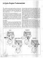
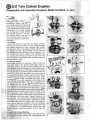
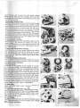
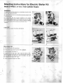
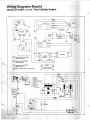
SVM-7735
Service Manual
I
For
G) JLO Axial-Fan Twin Cylinder Engine
Model LR-440/2
(2F-440-3)
• 2-CYCLE ENGINE FUNDAMENTALS
· • ENGINE BREAK-IN
• EXHAUST SYSTEMS
• DISASSEMBLY AND ASSEMBLY INSTRUCTIONS OF
BASIC ENGINE INCLUDING RECOIL STARTER
• ELECTRIC STARTER MOUNTING INSTRUCTIONS
• IGNITION TIMING PROCEDURE
• SPARE PARTS LIST; SERVICE TOOLS
I
2-Cycle Engine Fundamentals
The 2-cycle, air-cooled gasoline engine has become very
popular today for snowmobi les, ATV's and other recreational
vehicles. It is uniquely qualified for these applications because of its relatively high power output, light weight, and
ease of lubrication, with fewer moving parts than conventional 4-cycle engines.
However, in order to get the best possible use, and assure
that it retains its high degree of dependability and endurance, it must receive proper care and maintenance. Since
the life expectancy of any 2-cycle gasoline engine depends
to a great degree on the level of maintenance it receives,
it is necessary for us to know something about the basic
fundamentals of an engine and how it functions in order to
determine and apply, the correct amount of maintenance.
Operation
The JLO 2-cycle engine is of the loop-scavenged, 3rd-port
design type ... the most widely used design today. It uses
a mixture of gasoline and oi l for combustion, lubrication and
cooling. It f ires on every stroke of each piston. There are
two power strokes for every revolution of the crankshaft.
As the piston moves upward in the cylinder (Illustration A),
it draws the fuel/air mixture into the lower crankcase while
at the same time compressing the fuel already in the compression chamber above. As the piston nears T.D.C., the
spark plug ignites the compressed fuel and the burning
fuel expands and forces the piston downward on its second,
or power stroke (Illustration B). In this downward stroke the
piston not only turns the crankshaft but compresses a new
charge of fuel in the crankcase while continuing downward
clearing the exhaust ports (Illustration C) in the cylinder
wall to release the burned gasses through the ports and out
into the exhaust system. The piston continues downward
to uncover the transfer port and release the compressed
fuel charge into the cyl inder where it displaces the remaining burned gasses and forces them out through the exhaust
ports (Il lustration D).
Because lubrication of 2-cycle engines depends on mixing
predetermined amounts of oil and fuel, it is extremely important that good quality oil be thoroughly mixed with fuel and
in proper proportions. Whi le there are different engines, as
well as different oils, requiring different fuel mixtures, the
correct oil-fuel ratio required for Rockweii-JLO engines is
20 to 1. Use of little oil may cause engine over-heating,
piston or cylinder scoring and eventual engine seizure or
failure. Too much oil, on the other hand, leads to incomplete
combustion, carbon fouling of plugs and piston overload.
...
TRANSFER
INTAKE
EXHAUST
A
B
2
D·
C>
Carburetion
Spark Plug
In order to atomize the oil-fuel mixture and mix it with proper
proportions of air flowing to the intake port or intake manifold, it is necessary to utilize a carburetor. Carburetor design
is based on the venturi principle whereby a gas or liquid flowing through a restricted or necked-down passage increases
in velocity and decreases in pressure as compared to the
velocity and pressure in the full size section of the passage.
The spark plug provides the electric spark necessary for
ignition of the compressed fuel-air mixture in the cylinder.
There are many types and sizes of spark plugs, depending
on engine design and operating characteristics. Most single
cylinder, 2-cycle engines use the "short reach " type spark
plug, while the newer, angled-head single and twin cylinder
engines use the "long reach" type spark plug. The most commonly used thread sizes are 10 mm., 14 mm. and 18 mm.
Spark plugs tip temperatures are also extremely important
in proper engine operation , therefore, they should be
selected according to engine design and type of service
There are various
types of carburetors
classified by method of
delivery of fuel to the
carburetor: float, suction lift and diaphragm
type. JLO Engines
mainly use diaphragm
type
carburetors ,
therefore, future references herein will be
limited to this type of
carburetor.
Courtesy of
Walb ro
Carburetor
Corp.
Terminal nut
Insulator
Terminal bolt
Courtesy of
Tillotson Mfg. Co.
Crimping ring
Ignition
Gasket seal
The ignition system provides the high voltage electrical
energy which flows across the spark plug electrode gap to
create ignition spark. Most small engines are equipped with
magneto type ignition. The magneto ignition system generates and transforms electrical energy into high voltage, delivering it at the proper time for ignition spark.
Center electrode
Screw thread
Ground electrode
Courtesy of Robert B osch. GMBH .
Flywheel Magneto
Armature plate
G enerator armature for ignition
Flyweight for ignition timing adjustment
Courtesy o f R o b e rt Bosc h . G MBH.
Oxide magnet with pale shoe
Starting, Stopping, Fuel Mixture
Starting Procedure
1. Turn switch to "on" position.
2. Close choke (warm engine requires little or no choking).
3. Open throttle slightly when cranking the engine.
4. As soon as the engine starts open choke and release
throttle.
5. Electric start:
Turn switch to "start" position. Release as soon as the engine
starts (switch will remain in "on" position). Do not continue
cranking the engine if it fails to start after approximately 30
seconds. Allow the starter to cool before making another
attempt. If the battery is low use the recoil starter.
Operation
Before operating at full load, let engine warm up for a few
minutes.
Idling
Do not let the engine idle for prolonged periods as this may
result in carbon build-up, foul the spark plug or cause flooding.
Engines put under severe strain, may continue running after
the ignition is turned off. To stop the engine under these
• conditions, shut off the air supply by closing the choke.
Stopping Procedure
Release the throttle to allow engine to idle. Turn switch to
"off" position.
Do not use the choke to stop the engine. This can result in
carburetor flooding, making it very difficult to restart.
Safety Precautions
1. Never add fuel while the engine is running as spilled fuel
might ignite on contact with hot engine su rfaces. Stop
engine and allow to cool.
2. Always be sure .ignition switch is in "off' position before
working on engine.
3. Make sure all safety shields or guards on engine and
driven equipment are in proper position and secu rely
fastened .
4. When starting, keep hands, feet and clothing at a safe
distance from moving parts.
5. Do not operate the engine in closed buildings unless exhaust pipe is vented to the exterior.
4
Fuel Mixture
Gasoline Required
Gas/Oil Ratio
Ounces Of Oil
20 to 1
32
5 Gallons
20 to 1
26
4 Gallons
20 to 1
19
3 Gallons
20 to 1
13
2 Gallons
20 to 1
6.5
1 Gallon
NOTE: Mix gasoline (90 octane minimum), with SA E 30-40
air-cooled engine oil. Premix thoroughly before pouring into
vehicle tank by first mixing 1 gallon of gasoline with all the
oil, shaking vigorously and then adding the rest of the gasoline. Always use fresh, clean gasoline to avoid gumming up
or clogging the carburetor.
Volume Equivalents
1 U.S. Quart
= .946 Liters
1 U.S. Quart
= .833 Imperial Quart
1 U.S. Quart
=
1 U.S. Quart =
32 Ounces
2 U.S. Pints
0
Exhaust Systems
Tuned Mufflers, Expansion Chambers
Selection
Selection of an exhaust system (including exhaust manifold,
interm ediate pipes, elbows and muffler), is a result of
thorou gh test procedures involving measurement of fuel
consumption, horsepower and noise level. Contrary to popular belief, the exhaust system is not only for quieting the
engine, but also serves to increase the horsepower output
(by as much as 25%). Changes made to the original equipment exhaust system by changing any component in the
system can result in loss of power and/ or severe engine
damage. For these reasons, intermediate lengths of pipe
between the cylinder and the muffler are particul arly
critical.
back into the cylinder using sound waves and sound energy.
This is accomplished at the speed of sound which allows the
engine to produce higher torque at high RPM 's.
How Tuning Works
The megaphone effect of the expanded intake tube
scavenges exhaust gas from the cylinder, allowing rapid
replacement of the fuel-air mixture from the crankcase.
Reflected sound waves and sound energy stop overscavenging and return fuel-air mixture to the cylinder. It
gives a "super-charg ing" effect even though it operates from
the exhaust rather than the intake side. Over-scavenging
is also retarded by moderate muffler back pressu re.
Silencing is accomplished after power is maximized, by
Tuned Mufflers
acoustical packing in the resonator outlet tube plus chamTuned mufflers allow the engine to exhaust its spent charge bering and baffling which gives an effective 2-pass muffler
into an adequate volume and properly matched muffling design.
system. More important, the mufflers are "tuned ", incorporate designs that "suck" the exhaust gas from the cylinder Racing Expansion Chambers
allowing fuel and air to rapidly replace it and also "cram ·· Expansion chamber incorporates power-tuning to increase
over-scavenged fuel and air mixture from the exhaust pipe horsepower of two-cycle engines up to 25 per cent.
Typical Exhaust Systems
ACS
Donaldson
Tuning
Co urtesy of D on ald so n Muffi e r Co .
Expansion Chamber (Racing)
f)JLO Twin Cylinder Engines
Disassembly and Assembly Procedure - Model LR-440/2
(2F-440-3)
Disassembly
A. Recoil Starter
Remove four screws holding recoi l to fan housing and the
spacers and washers. Remove recoil assembly, complete.
(For detailed service instructions refer to Recoil Starter,
Disassembly and Assembly}.
A
B
- ~
~
B. Lower Fan Pulley and Carrier Assembly
Remove three hexhead screws on carrier. Remove dust
seal, carrier, lower pulley halves and V-belt.
C. Upper Fan Belt Pulley Assembly
To keep impeller from turning, insert a punch through the
fan housing and into the impeller body. With a 17 mm .
wrench, remove fan nut. Pull out the loosened assemblynut, washer, spacers, and upper pulley halves.
D. Flywheel Magneto
Make sure spark plugs are tight. Working against engine
compression, w ith a 27 mm. wrench, remove crankshaft nut
by striking wrench a few sharp blows with a hammer. To pull
flywheel, attach special puller to flywheel flange, using three
of the recoil starter screws previously removed . Screw into
the three holes on flange and tighten . Turn puller until bolt
touches tip of crankshaft. With a 24 mm. socket wrench, turn
puller bolt clockwise and extract flywheel. Note that key may
come loose and adhere to the flywheel magnets.
~. ~>
c
D
~
E. Intake Manifold
Remove the four nuts holding manifold and upper coil cover,
plus the two lower coil cover screws. Remove screw holding
spark plug wire to side of fan housing.
F. Fan Housing; Armature Plate
With a special Allen Head wrench, remove t he 4 socket cap
screws holding fan housing to crankcase. To loosen, place
unit with fan housi[lg protrud ing over end of workbench and,
holding housing with one hand, hit light but sharp blows
around periphery. Pull housing straight out past the crankshaft careful not to cut the oil seal on the sharp edges of
keyway of the shaft. Disconnect solid blue and blue-yellow
coil wires and remove entire assembly. The armature plate
is attached to the fan housing by two slotted screws and can
be removed at this time. Scratch-mark its original position
before removal as this will facilitate engine timing. Impeller
assembly should come loose and may be removed at same
time as fan housing assembly. The fan housing bearings can
be removed at this time, if necessary, by punching out from
the side opposite that from which they are normally inserted.
6
D
F
0
F
F
c
G. Spark Plugs
Remove with special socket wrench.
H. Cylinder Heads
Remove the 17 mm. head nuts and lift head and gasket from
cylinder block. Mark cylinder head and corresponding
cylinder in order to assure proper reassembly. (Cylinder
c losest to the P.T.O. end is always considered No. 1 cylinder.)
Repeat operation for second cylinder.
I. Cylinders
Lay unit on end and with a 13 mm. socket remove the 8
cylinder-base nuts. (Unless complete disassembly is required, remove one cylinder at a time so as to maintain
crankcase alignment.) Set unit upright again and lightly tap
cylinder with a rubber hammer and lift gently until piston
clears the skirt. Repeat operation for second cylinder.
J. Piston and Wrist Pin
Prior to removing mark each piston in relation to the cylinder
with which it mates. With needle-nose pliers or special
screwdriver remove the two different circlips on each side
of wrist pin. Gently drive out wrist pin. Repeat operation for
piston No. 2.
K. Crankcase
To separate cran kcase halves, hold upper shell w ith left ·
hand and " rock" slightly back and forth to break the sealing
surfaces. If necessary, strike side of crankcase with rubber
hammer to complete the separation. Remove crankshaft.
L. Crankshaft; Crankshaft bearings
With crankshaft on work surface, remove oil seal and alignment washer from P.T.O. end. To remove bearings use
special puller. Slide puller body over crankshaft and align
bolt with cran kshaft end. Slip puller half-shells around the
bearing and engage them on puller grooves. Slide retaining
ring over half-shells to keep them on the bearing. Using two
27 mm. wrenches, turn puller center bolt with one wrench
while holding puller body with the other. Keep turning puller
center bolt clockwise until it pulls the bearing to the end of
the crankshaft.
J
J
K
K
l
l
7
0JLO Twin Cylinder Engines
Disassembly and Assembly Procedure- Model LR-440/2
(2F-440-3)
Assembly
1. Crankshaft
Heat crankshaft bearings in oil
preheated to 180° F. After reaching
temperature, quickly slip bearing
over end of crankshaft; it should fall
freely on the counterweight. Using
a hollow pipe with a diameter approximately that of the inner bearing
race, hit pipe with a rubber hammer
and seat the bearing on the shaft.
The bearing should now rest securely and turn freely. Repeat pro1
cedure for bearing on other end of
c rankshaft.
2. Crankcase
Inspect both halves of crankcase and clean carefully
removing any left-over adhesive or burrs. Apply Permatex
type sealing compound to lower crankcase shell sealing
surfaces and a little on the bearing surfaces. Note that no
seal gaskets are used. Place crankshaft in lower shell and
align spacers with machined grooves. Place oil seal on P.T.O.
end of shaft flush with the casting. Turn crankshaft with
your hand to check freedom of movement and make sure
that the oil seal is seated. Install upper crankcase shell and
seat by tapping it lightly.
-
2
2
2
3. Piston and Cylinder
Clean carbon deposits from the piston. Check to see that
rings move freely in their grooves. Mate piston with corresponding cylinder. The piston must be installed with the
arrow pointing toward the exhaust port. Insert needle bearir}gs into the connecting rod, then place a daub of grease
on the connecting rod so that the spacers installed later will
adhere to it. Gently guide the piston over the connecting
rod and insert the wrist pin. Snap circlips into each side of
the piston using a screwdriver or needle-nose pliers. Install
cylinder base gasket. Place a V-shaped wood block under
the piston, resting it on the crankcase. After lining up the
rings with the locating pins on the piston, compress them
with a ring compressor. Rest the piston on the wood block
and carefully slide the cylinder over the piston until the
rings disappear i.nto the cylinder. Be sure you use a gasket
of the same color as was removed from the engine because
there are four gaskets available having different thicknesses.
Note that the top of the piston must be within ± 0. 008" of the
top of the cylinder. Use a gasket whj ch will achieve this
result.. Mark the dimension on the cylinder in pencil. Remove
ring compressor and wood block. Repeat procedure for
second cyl inder. Turn the unit over on its side and install the
cylinder base nuts and tighten lightly. Assemble the intake
man ifold and tighten the four screws. Draw nuts tightly in
order to evenly align both cylinders. Turn unit completely
over (upside down) and torquedown the cylinder base nuts
to specifications in a crosswise pattern. Remove the inlet
manifold assembly (previously installed only to align the
cylinders).
4. Impeller; Fan Housing Bearings
Install fan housing spacer and circlips- (one circlip on each
side.) Pack fan housing opening with bearing grease and
8
3
3
c
c
insert bearings-one on each side, with sealed surfaces
facing outward. Sl ide shaft thru impeller and install N ilos
ring on the side of the impeller wh ich faces the housing, and
then thru the bearings.
5. Fan Housing; Armature Plate
Install the armature plate aligning it with the scratch marks
previously put on during disassembly. Tighten slotted
screws. Check the wiring protruding from the fan hou sing to
make sure that there are no broken wires. Slip the rubber
grommet protecting the wires into the housing. Check the
0 -rin g on the back side of t he fan housing and the oil seal for
c uts or other visible damage. Pass the fan housing over the
crankshaft and avoid hitting the sharp edges of the keyway.
Adjust the housing against the crankcase and insert the four
screws with the special Allen Head tool. Tighten Allen Head
Screws in crosswise pattern.
6. Intake Manifold; Coil Cover
Install intake manifold assembly and gasket; tighten the two
upper manifo ld nuts. Connect the ignition coil wires to
terminals. Replace coil cover making sure to reconnect the
No. 2 cylinder ground wire (brown). Fasten spark plug wire
clip to fan housing.
7. Upper Axial Fan Belt Pulley Assembly
Insert Nilos rin g, first tapered spacer (dished side towards
fan), first pulley half, four adjustment shims, second pulley
half, second tape red spacer (dished side facing outward),
washer and nut. Note: block impeller with a punch when
tightening nut.
8. Flywheel Magneto; Ignition Timing
Align magnetic flywheel with keyway; insert and tap key
into position. Lightly tighten fl ywheel nut. For timing details,
see Ignition Timing Procedure.
9. Cylinder Heads
Install cylinder head gaskets. If piston is below the cylinder
by 0-.008" use cylinder head 438-07-006-00. If piston is
above cylinder by 0-.008" use cylinder head 438-07-007-00.
The gap between the piston and cylinder head must be
measured after assembly. This is done by introducing a thick
piece of solder into the spark plug hole at a 90° angle to the
crankshaft with the end toward the inlet side of the engine.
Rotate engine once and then remove solder. Measure the
thickness. It should be between .040" and .060". If it is not,
achieve this by chan gin g heads and/or head gaskets.
Assemble cylinder heads with corresponding cylinde rs and
install washe rs and nuts. Tighten to specifications.
10. Spark Plugs
Install and tighten spark plugs. Com plete tightening of
flywheel nut.
11. Lower Axial Fan Belt Pulley Assembly
Install t he first pulley half wi th dished side facing the housing,
the fan be lt , the second pu lley half with the dished side facing o ut and the carrier assembly. Tig hten carrier screw s
while slowly rotating the crankshaft with your hand to preve nt squeezing the fan belt.
12. Recoil Starter
Install recoil starter assembly using the four hexhead screws,
clamps and lockwashers. For service details, refer to Recoil
Starter Service Instructions.
5
6
6
7
7
8
8
9
12
9
(DJLO Twin Cylinder Engines
Disassembly and Assembly Procedure- Recoil Starte·r,
Model LR-440/2
(2F-440-3)
Disassembly
A. Take off cover plate and gasket ring by removing three
slotted or Philipps head screws.
B. Lift out pawl assembly, including spring caps and pressure
springs.
C. Remove intermed iate plate.
D. Remove handle assembly. To provide needed slack for
removal of handle, pull rope part way out and tie a knot.
g
:..\,),..
A
e
li>
c
B
E. After removing hand le, untie knot in rope and careful ly
release spring tension by holding recoil pulley with one
hand and letting the rope feed back slowly to gradually
release spring tension.
F. Remove nylon rope bushing.
G. Lift out rope pulley with pliers. Keep coil spring in position
using a screwdriver.
D
E
H
H. Turn recoil housing upside down in your hand and smack
down sharply against workbench. This will release spring
tension within the housing enabling you to grasp the sp ring
and gradually and safely uncoil it.
Assembly
1. Clamp the special assembly jig in a vise.
Insert recoil housing in jig and lower the hub, locking it in
position with a cotter pin. Hook end of spring onto the small
boss cast in the housing and start rotating the housing clock~ise, slowly guiding the spring into position. Complete the
recoiling and remove housing from the jig.
2
1
~
2. With rope pulley in one hand and a Philipp's screwdriver
in tne other, guide the screwdriver into the spring loop and
engage the end of the spring on the pulley hub. The spring
loop must be properly seated on the pulley hub.
3. Before installing rope, turn rope pulley counterclockwise
as far as possible. Back-off 1/2 to 3/4 of a turn and jam
punch or screwdriver between pulley and housing to maintain tension. Align rope hole with outlet of starter housing
and insert the rope. Install nylon bushing and handle
assembly. Remove screwdriver and release tension while
guiding the rope into the starter housing.
3
3
4
5
4. Install the Intermediate Plate.
5. Install Starter Pawl Assembly.
6. Install cover plate and gasket ring. Note: when installing
cover plate the spring cups have a tendency to become
misaligned. To retain them, use a pair of clips.
3
7. Check the complete assembly for free play.
,
6
10
6
Mounting Instructions fo~ Electric Starter Kit
c
Model LR-440/2
(2F-44.0 -3)
Twin Cylinder Engine
Installation
1. Install front mounting bracket on c rankcase using the two
socket cap screws provided.
2. Insert starter unit into front bracket and loosely fasten with
2 hexhead screws.
3. Loosely install the rear support bracket to the starter.
Now, fasten support bracket to the engine and then go back
and firmly tighten it to the starter. Note: to simplify installat ion of re ar bracket the engine mounting holes may be
"slotted ".
Removal
1
1
1. To remove, reverse the above procedure.
c
3
Ring Gear Kit
A. Pry out oil seal with screwdriver.
B. Insert new, larger seal flush· with the crankcase.
C. Lightly grease ring gear hub.
,.
D. Install the two ring gear wedge ring s as follows: first,
insert the smaller of the two rings into the ring gear opening
with the tapered end facing you; then the larger ring with
the tapered end facing the engine.
E. Insert pressure f lange and tig hten .
11
Timing Procedure
Model LR-440/2
(2F-440-3)
Twin Cylinder Engine
With the recoil starter and carrier assembly removed,
proceed as follows:
A. Attach the dial indicator to the cylinder. (Make a small
notch in the cylinder head cover, around the spark plug area,
to accept the timing device).
B. Turn the flywheel clockwise towards TDC (top dead
center) until breaker points are visible. Use a clean feeler
gauge and adjust the gap. Note: if flywheel is removed, use
an old cam and rotate until the points are at their largest
opening. Check gap and adjust to specifications as necessary. Repeat procedure for the other set of points.
C. Advance the centrifugal weight. Hold in place using
locking pin, (a tool specially designed for this purpose. )
I
D. Attach one lead of the ignition continuity light to terminal
of No. 1 cylinder coi l, the other to ground (engine casting).
For the second cylinder, attach continuity light lead to No. 2
cylinder coil terminal, (solid blue wire is for No. 1 cylinder;
blue-yellow wire is for No. 2 cylinder).
Oxid e magnet
with pole shoe
B
Courtesy of Robert Bosch , GMBH.
E. Bring piston to TDC and adjust dial to zero.
F. Working with No. 1 cylinder, turn flywheel counterclockwi se (away from TDC), closely observing dial indicator and
. timing light. When piston reaches the timing point, the light
will dim indicating the opening of the points. Now, check
the dial indicator. If timing does not agree with specifications, do not change the breaker point gap; adjust by loosening and rotating the stator plate assembly (lllus. F). Rotate
assembly clockwise to retard, counterclockwise to advance
the ignition . Correct breaker point gap will insure maximum
ignition output. Important: to time cylinder No. 2 repeat
procedure for cylinder No. 1 except do not rotate armature
plate. If timing of No . 2 cylinder is required, ad j ust the
breaker point gap only.
t
o
.=-------------=:.........
B rea k e r Poi nt Lockscrew
F
It -
NOTE: Rockwe/1-Jio axial-fan twin cylinder engines have
timing marks cast on the fan housing. This makes it possible
to check timing while the engine is running. Use an automotive type strobe light and aim at the timing marks. If the
notches on the flywheel are not in alignment with the marks
on the fan housing, the engine is out of time. Note that there
are two notches on the flywheel-one for each cylinder.
This permits instant timing check of both cylinders.
A quick timing check can also be performed with the engine
not running. With centrifugal weight in retard position, attach
the timing tester to the coil wire terminals and slowly turn
the engine over by pul/(ng on the recoil starter. Once the
notch on the flywheel is aligned with the mark closest to the
center, the timing tester light should dim. If the light does
not dim when both timing marks are in alignment, the engine
needs retiming.
12
Courtesy o f R o b ert B osch_. GMBH .
0
c
c
Specifications
Model LR-440/2
(2F-440-3)
Twin Cylinder Engine
Bore
2.658"
Stroke
2.362"
Displacement
428cc
Compression Ratio
7.5 to 1 (Actual)
Maximum Torque
28.4Ft./Lbs.
(BHP) at 6000 RPM
Brake H.P./RPM
37.5 H.P. at 6250 RPM
Lighting Coil
12 Volt, 75 Watt
Contact Breaker Gap
.014" to .016"
Ignition Setting Before TDC
(Cam Fully Advanced)
.083" to .102"
Spark Plugs:
Thread
Gap
Type:
Medium Load
Full Load
Racing
14 x 1.25 mm. Long Reach Type
.016" to .020"
BOSCH
W-240-T-2
W-260-T-2
W-310-T-17
Rotation
Counterclockwise, viewed from P.T.O. End
Fuel-Oil Mixture
20:1 (1 Qt. Oil to 5 Gals. Gasoline)
Lubrication
Mixture of Good Brand of Gasoline (90 octane minimum)
and Special Two-Cycle Engine Oil
Carburetor Type
WD or HD
Starter
Rewind Type, Standard ; Electric, Optional
Recoil Rope
Steel
Weight
62 lbs.
13
Wiring Diagrams (Bosch)
Model LR-440/2
(2F-440-3J
Twin Cylinder Engine
II
Ye llow
JLO
Brown
ENGINE
4 -
I-IWIILIU.o¥.J...,..L._ _ __
5-
1-.:..:..:.:.:..:._=.t..;_:....:..:__ __
8
SPARK
PLUG~
12 VOLT
BATIERY
RECTIFIER
Q
0
@
Terminal 85 needed far rubbermounted solenoid an ly.
0
Packard cooonectar 31 380 80
and blades 296 54 81.
Packard connector 297 34 22
and blades 296 55 10 .
(Vu.e 12 volt battery cable.
All others 14 G .
Packard
1.
2.
3.
4.
5.
9.
10.
11 .
12 .
13.
B atte ry
M agn e t o
Rectifi e r
High te n sion coil
Packard connector
Starter
Solenoid
Ke y switch
lights
Spark plugs
®
~
black
+
r _·-,
'
CD
I
I
I
I
I
-·-
G)
I
~ I _j
14
@
Dimensional Drawing and Speciai .Service Tools
c
Model LR-440/2
(2F-440-3)
Twin Cylinder Engine
Dimensional Data, Standard Configuration
· - - 1205
4f
I
;0 i
_;;;~_i i
f
-
·-
-·=----r
r
l.
'
-; o.
Q~---o
Connector Body
1
(3138080)
/
PACKARD CONNECTOR TERMINALS
CD
GROUND WIRE
@@ LIGHT WIRE
@ ® SHORT CIRCUIT WIRE
----1---- _____ j __________i
Special Service Tools
1
5
6
~
I
I
~
9
~
~ rr~ ~
e-, ~ ~
-~ - ~
ffi~
~
~"'a
I
I
I
2
n '
4
7
•
-
•
Ill us.
No.
Description
Part No.
Qty.
Req'd.
444-31-807-00
444-31-072-00
444-31-071-00
444-31 -843-1 0
444-31-666-00
444-31 -863- 10
000- 15-30-0 10
444-31 -804- 10
000-15-20-421
1
1
1
1
1
1
1
1
1
000-15-21-012
444-31-68 2-00
1
1
I•
1
2
3
4
5
6
7
8
9
10
11
Bearing Puller
Half Shells (2)
Retaining Ring
Flywheel Puller
Guide Pin
Assembly Jig (starter)
R.P.M . Indicator
Universal Mounting Plate
Spark Plug Wrench,
14 mm.; single end
Bar (use with sockets)
Wrench, double,
13 x 17 mm., open end,
offset to clear carburetor
-Gasket Set with Seals
..
438-61 c80 2-00
1
-
15
Spare Parts List
(2F-440-3)
Model LR - 440/2
T in Cylinder Engine
W
General View
Ill us.
No.
6
16
5
4
Description
Part No.
Crankcase. c omplete,
·thU.N.C.
d (Use WI
base threa
or ~lectric starter)
standard
lmpu lse Connector
Screw Plug
Gasket Ring
Hexagon Screw
Washer
Nut
·ng Washer
SpnSeaI (Electric Start)
Oil
Grommet
338-01-810-20
002-45-513-26
000-4 1-48-053
000-35-00-070
000-41-01-089
338-03-007-00
000-4 1-97-010
000-40-42-209
000-4 2-31 -891
002-44-430-00
c
Crankshaft
Piston and Cylinder
3
~
-1- ~--
2
~--11
3
10
I
I
~- @-
<>--9
®
-
.
'
Ill us.
No.
1
2
3
4
5
6
7
-6
Description
Crankshaft, complete
P.T.O. with 1/2"-20
U.N. F. female thread;
(including items 2 thru 6).
Needle Bearing
Check Plate (Spacer)
Key
Nut
Lock Washer
Ball Bearing
Part No.
Qty.
·Req'd.
338-86-904-00
1
·~-::· .
Ill us.
No.
000-39-11 -253
338-03-006-1 0
000-40-89-615
OQ0-41-95-507
000-40-64-5 20
000-39-07-521
2
4
1
1
1
2
2
3
4
5
6
When ordering spare parts:
1) Indicate engine model number and serial number.
2) Order parts by part number, not by illustration number.
3) Give exact description of part required.
4) Indicate quantity required.
14
19
16
17
18
19
Description
Piston (including items
2 thru 5)
Piston Ring
Piston Ring
Wrist Pin
Circlip
Cylinder, includes
illustration 7, studs
Stud
Cylinder Head
Cylinder Head
. Cylinder Head Gasket
Washer
Nut
Stud
Cylinder Base Gasket
Yellow; 5 mm.
Red; 3 mm.
Yellow-brown ; .75 mm.
Grey; 1 mm.
Intake Gasket
Intake Manifold, HD
Nut
Spring Washer
Nut (HD only)
Lock Washer (HD only)
, •J.ype and quantity as required.
Part No.
Qty.
Req'd.
438-05-911-00
2
000-42-12-488
000-42-14-488
338-05-002-00
000-40-62-142
438-07-814-10
2
000-41-24-085
438-07-006-00
438-07-007-00
438-07-002-00
000-40-51-01 0
000-41 -~7-011
000-41--24-360
338-0 7-008-00
338-07-025-00
338-07-026-00
338-07-027-00
338-07-011-00
338-07-017-00
000-41-97-010
000-40-42-209
000-41 -96-011
000-40-64-508
.
2
2
4
2
8
2*
2*
2
8
8
8
*
*
*
*
2
1
4
4
2
2
(See ite m s 3 and 9 Engine A ssembly
Procedu re) .
'
17
Spare Parts List
Model LR-440/2 (2F-440-3)
Electrical Equipment (Bosch)
Ill us.
No.
44- --ffy-38
43-~......_39
41-
-
·
.,~~;~1
37 30
Ill us.
No.
..;
-~
18
19
22
25
26
r ff~~·
20
Description
1
Magnetic Flywheel
.artf·. Armature Plate
3 ' · Cam
4
Centrifugal/Weight
5
Ignition Points (2)
6
Condenser
•
7
Generator Coil t 8
Generator Coil
9
Lighting Coil
10
Lubricating Wick
11
Washer
12
Lock Washer
13
Screw
14
Spi ral Spring
15
Ring Segment
16
Lock Washer
17
Socket Cap Screw
18
Washer
19
Lock Washer
20
Grommet
21
Spiral Band
22
Ignition Coil
23
Socket Cap Screw
24
Spring Washer
25
Protective Cap
26
Protective Cap
27
Ground Cable (4YlG")
· 28
Connector
.29
Cable-Connector
30
Socket Cap Screw
31
Magnetic Flywheel Flange
32
Ignition Cable (14")
,33
Ignition Cable (20~6")
34
Spark Plug Connector
35
Spring
36
Contact Nut
37 · Cover Plate
28
21
27
. · ParPN.o.
000-43-05-198
000-43-05-331
000-43-05-728
000-43-06-0 19
000-43-06-223
000-43-06-530
000-43-05-53 7
000-43-05-538
000-43-05-534
000-43-06-313
000-43-12-531
000-40-76-008
000-41-50-094
000-43-08-768
000-43-12-538
000-40-64-504
000-4 1-50- 115
000-40-51-006
000-40-64-505
002-44-450-01
002-44-127-16
000-43-05-606
000-41-50-434
000-40-42-208
002-44-498-00
002-44-499-00
002-44-140-11
002-44-523-00
000-43- 10-004
000-4 1-50- 1 20
338-11-002-11
002-44- 152-36
002-44-152-52
002-44-275-00
002-44-276-00
002-44-277-90
338-11 -008-1 0
38
39
40
41
42
43
44
45
46
47
Part No.
Qty.
Req'd.
000-41 -50-097
000-40-51 -005
000-40-64-504
000-41 -97-006
002-44-556-00
002-44-550-00
002-50-120-08
000-41 -50-438
000-40-42-208
002-44-4 72-90
2
2
2
2
1
5
1
1
1
2
Description
Socket Cap Screw
Washer
Lock Washer
Nut
Terminal Case
Connection
Ignition Cable Bracket
Socket Cap Screw
Lock Washer
Grommet
Electric Starter (Bosch)
16 12 15 18 4
17
3
2
~~~~
29
Qty.
Req'd.
1
1
1
1
2
2
1
1
1
1
2
1
3
1
1
3
2
2
6
1
1
2
4
4
4
2
2
4
2
4
1
1
1
2
2
2
1
Ill us.
No.
2
3
4
5
6
7
8
9
10
11
12
13
14
15
16
17
18
19
20
21
22
23
24
25
26
Description
Starter, complete
(incl udes 2 thru 9)
Field Winding
Armature
Bushing
Bushing
Bushing
Drive Gear
Brushes (set of 4)
Pressu re Spring
Bracket
Socket Cap Screw
Lock Washer
Hexagon Screw
Nut
Bracket
Hexagon Screw
Nut
Spring Washer
Starter Gear
Pressure Flange
Clamping Ring (set of 2)
Oi l Seal
Hexagon Screw
Lock Washer
Rectifier
Relay
Part No.
Qty.
Req'd.
00 2-44-03 7-00
000-43-08-313
000-43-05-533
000-43-0 7-81 2
000-43-07-801
000-43-0 7-806
000-43-07-421
000-43-08-7 45
000-43-08-773
338- 11-01_1-00
000-4 1-75-032
000-40-64-500
000-41 -01 -093
000-41-97-010
338-11-021-00
000-4 1-01-067
000-41-97-007
000-40-42-207
338-11 -0 10-00
338-11-01 5-1 0
002-4 2-640-30
000-42-31-891
000-41-74-011
000-40-64-508
000-43-08-352
0.00-43-15-008
2
1
1
1
1
1
1
2
1
2
8
2
2
1
2
2
2
1
1
1
1
4
2
1
0
c
Fan Case
Recoil Starter
4
18
Ill us.
No.
1
2
3
4
5
6
7
8
9
10
11
12
13
14
15
16
17
18
17
Description
Fan Case
Impeller
Shaft
Nilos-Ring
Ball Bearing
Spacer
Locking Rin g
Clamp Washer
Pulley Half (Small)
Spacer
Lock Washer
Nut
Socket Cap Screw
Lock Washer
Pulley Half (Large)
V-Belt
Oil Seal
0-Ring
8
9
10
9
8
11
12
16
Part No.
338-14-017-00
399-14-004-00
338-14-007-0~
000-40-47-735
000-39-07- 113
338-14-008-00
000-40-61-43 2
338-14-009-00
399-14-002-00
338-14-012-00
000-40-64-51 0
000-41 -95-202
000-41-74- 128
000-40-64-60 7
399-14-001 -00
000-4 2-1 7-508
000-42-31 -548
002-52-665-00
Ill us.
No.
Qty.
Req'd.
1
1
1
2
2
1
2
2
2
4
1
1
4
4
2
1
1
1
1
2
3
4
5
6
7
8
9
10
11
12
13
13A
14
15
16
17
18
19
20
21
22
23
24
25
Description
Recoil Starter Assembly
complete (includes items
1 thru 19); 65" rope
Recoil Starter Housing
Rope Drum
Recoil Spring
Intermediate Plate
Cover Plate
Starter Pawl
Spring Cap
Pressure Spring
!rine r Spring Cap
Screw
Lock Washer
Rope Bushing
f:landle ; complete (includes
items 13A thru 16).
f:fandle
Bus ing
Retaining Ring
Retaining Key
Tensional Pin
Rope; 65"
Gasket
Carrier
Dust Seal
Socket Cap Screw
Lock Washer
Hexagon Screw
Recoil Starter Clamp
Part No.
Qty.
Req'd.
338-41-811 -00
338-4 1-0 17-00
197-41 -070-00
252-41 -429-21
338-4 1-006-00
338-41-005-00
252-4 1-065-10
252-4 1-066-00
252-41 -067-00
102-41-499-00
000-41 -50-098
000-40-67-005
10 2-4 1-469-00
102-4 1-801-00
252-41-007-00
252-41-009-00
252-41-015-00
252-41-016-00
000-40-39-145
252-4 1-807-00
338-41 -007-00
338-41 -810-00
079-11~017-00
000-41-50-136
000-40-64-506
000-41-01-069
338-41 -0 16-00
1
1
1
1
1
2
2
2
2
3
3
1
1
1
2
1
1
1
1
4
7
3
4
\
19
Rockwell JLO Engines
WARRANTY
Rockweii-Jio as manufacturer, warrants each engine for a
period of 90 days from date of original retail purchase, or
from November 15, 1971, whichever is later. Under this
warranty Rockweii-Jio will replace for the original purchaser
any part or parts found , upon examination by an authorized
service outlet or by central warehouse distributor, to be
defective in material and/or workmanship.
All transportation charges on parts submitted for warranty
shall be borne by purchaser.
This warranty shal l not apply to Rockweii-Jio products which
must be replaced or repaired due to normal wear, misuse,
negligence or accident or which have been repaired or
altered outside Rockweii-Jio's authorized service outlets.
--~.
There is no other warranty expressed or implied; and
Rockweii-Jio shall be under no liability whatsoever in respect
of any loss, damage, injury or expense arising from any
defect in said product or products.
'·
. ..'
I
I
',i
//
I
scorpion, inc.
CROSBY, MINN ESOTA 5644 1
S VM - 773 5 6/7 1 - 7 .5 M
P r in te d in U .S .A .