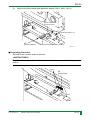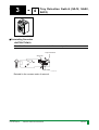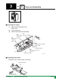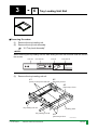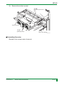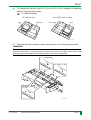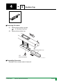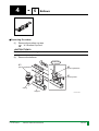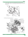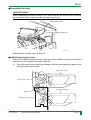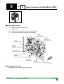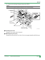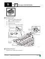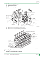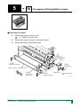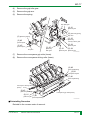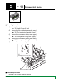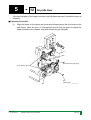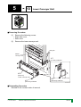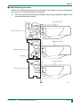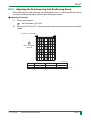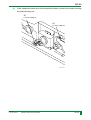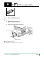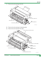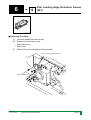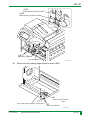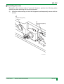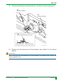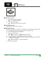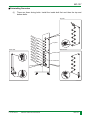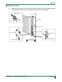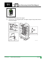
1
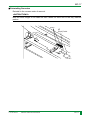
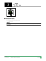
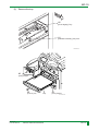
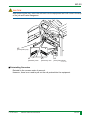
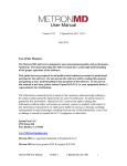
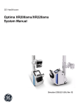
DRYPIX 7000
SERVICE MANUAL
REMOVAL AND ADJUSTMENT (MC)
MC-1
CONTROL SHEET
Issue Date
Revision Number
Reason
10/15/2002
11/10/2002
00
01
New release (FM3343)
Revised (FM3601)
04/01/2003
02
Revised (FM3978)
006-259-02
04.01.2003 FM3978
DRYPIX 7000 Service Manual
Pages Affected
All pages
1, 3-11, 13-17, 20, 22, 23, 26, 27,
33-39, 44, 46-149
1, 10, 11, 15, 16, 22, 23, 28, 31, 35,
37, 44, 54-57, 60, 75-77, 90-94,
107-109, 118, 120, 135, 141-149
MC-1
MC-2
PRECAUTIONS ON INSPECTIONS, REPLACEMENTS,
AND ADJUSTMENTS
This chapter does not describe parts which require no special note or adjustments in
removal and installation.
For details on the removal of these parts, refer to the Parts List.
Also follow the precautions below when performing inspections, replacements, and
adjustments of parts.
WARNING
To prevent electrical shocks, be sure to turn OFF the power of this equipment
before starting work.
WARNING/CAUTION
Observe the warnings and cautions described in “SAFETY PRECAUTION”.
CAUTION
Be sure to wear a wristband for grounding when performing maintenance of boards and
optical units. Otherwise static electricity in the body may cause damage to electronic
parts on the boards and optical units.
CAUTION
Never remove the screws painted in red.
<INSTRUCTIONS>
The screws painted in yellow must be adjusted after the installation of parts.
When installing parts, follow the check/adjustment procedure provided.
<NOTE>
When removing the covers, insert shutter into the film tray to prevent exposure of film to light.
006-259-00
10.15.2002 FM3343
DRYPIX 7000 Service Manual
MC-2
MC-3
The diagrams in this manual displays the CHECK and FIT ON icons where necessary.
When removing/reinstalling, following these icons.
• CHECK icon:
CHECK
• FIT ON icon:
006-259-01
11.10.2002 FM3601
When reinstalling removed parts, this is indicated if reinstalling
positions must be checked or adjusted.
This symbol is shown inside illustrations of parts removal
procedures. Whenever this is shown, be sure to refer to "■ CHECK/
Adjusting procedure".
When installing parts, this is indicated if alignment to the boss is
required.
DRYPIX 7000 Service Manual
MC-3
MC-4
HOW TO READ REMOVAL AND ADJUSTMENT VOLUME
The REMOVAL AND ADJUSTMENT (MC) Volume is constructed in such a way that it
can be referred together with the SERVICE PARTS LIST (SP) Volume.
The following describes how to refer to this REMOVAL AND ADJUSTMENT (MC)
Volume.
■ Example (REMOVAL AND ADJUSTMENT Volume)
Chapter No.
5
3
(1)
Upper Conveyor Unit Exit Motor (MD2)
Section. No.
(2)
FP7C0523.EPS
■ Removing Procedure
(1)
•
(2)
(3)
Remove the following cover.
Rear cover
Remove the conveyor unit exit clutch (CLD1)
Remove the exit conveyance motor (MD2).
(3) #3
[Disconnect]
Connector MD2
(3) #3
[Disconnect]
Connector CLD1
(3) #3
[Release] Clamp
(3) #4
[Disconnect]
Clutch connector
(3) #1
[Remove] 2-DT3x6
(3) #2
[Remove]
Upper conveyor unit exit motor (MD2)
(2) #1
[Remove] E5
(2) #2
[Pull out]
Upper conveyor unit exit clutch (CLD1)
FP7C0504.EPS
■ Reinstalling Procedure
Reinstall in the reverse order of removal.
006-259-01
11.10.2002 FM3601
MC-58
FP7C0005.EPS
(1) Chapter No. .. The Chapter No. in the REMOVAL AND ADJUSTMENT Volume is related to
the INDEX No. of the SERVICE PARTS LIST Volume.
(2) Section No. ... The Section No. in the REMOVAL AND ADJUSTMENT Volume indicates
enclosed REF. No. (example 3 ) in the SERVICE PARTS LIST Volume
(exploded view).
For the above example, the item to be referred for “MC
Conveyor Unit Exit Motor (MD2)” is “SP 05C 3 ”.
006-259-01
11.10.2002 FM3601
DRYPIX 7000 Service Manual
5
3
Upper
MC-4
MC-5
■ Example (SERVICE PARTS LIST Volume)
(1)
INDEX No.
05C
E6
FP7Z0513.EPS
15
(2)
REF. No.
3
2
16
2-BR3X8
1
4
E6
6
E4
E3
DT3X6
14
5
E6
8
6
13
10
E6
6
7
17
6
E6
9
DT3X6
10
3-BR3X10
11
18
12
FP7Z0503.EPS
006-259-01
11.10.2002 FM3600
SP-30
FP7C0006.EPS
To refer to the service parts information on “MC
(MD2)”, refer to “SP 05C 3 ”.
006-259-01
11.10.2002 FM3601
DRYPIX 7000 Service Manual
5
3
Upper Conveyor Unit Exit Motor
MC-5
MC-6
CONTENTS
1. COVERS
1.1 Covers
MC-10
2. FRAME
2.1 BCR Assembly
MC-12
3. TRAY LOADING UNIT
3.1 Tray Loading Unit
3.2 Tray
3.3 Film Pack/Shutter Detection Sensor
(SA11, SA21, SA31)
3.4 Tray Detection Switch (SA12, SA22,
SA32)
3.5 Tray Lock Assembly
3.6 Tray Loading Unit Rail
3.7 Tray Rail
3.8 Squeezing Roller
3.9 Special Screw
MC-14
MC-18
MC-22
MC-24
MC-25
MC-26
MC-30
MC-32
MC-34
FP7C0001.EPS
006-259-01
11.10.2002 FM3601
DRYPIX 7000 Service Manual
MC-6
MC-7
4. REMOVAL UNIT
4.1
4.2
4.3
4.4
4.5
Removal Unit
Removal Drive Cam
Suction Cup Arm
Suction Cup
Bellows
MC-36
MC-40
MC-44
MC-48
MC-50
5. CONVEYOR UNIT
5.1
5.2
5.3
5.4
Upper Conveyor Unit
Film Positioning Motor (Lower) (MD6)
Upper Conveyor Unit Exit Motor (MD2)
Cleaning Roller Grip Release Motor
(MD4)
Film Positioning Assembly (Lower)
Film Positioning Motor (Upper) (MD5)
Film Positioning Assembly (Upper)
Conveyor Unit Exit Guide
Conveyance Driving Roller (Upper)
Conveyance Driving Roller (Lower)
Conveyor Unit Guide
Grip Idle Gear
Lower Conveyor Unit
MC-52
MC-58
MC-60
Sub-Scanning Unit
Sub-Scanning Motor (ME1)
Sub-Scanning Roller
Film Leading Edge Detection Sensor
(SE1)
MC-82
MC-92
MC-94
MC-98
5.5
5.6
5.7
5.8
5.9
5.10
5.11
5.12
5.13
6. SUB-SCANNING UNIT
6.1
6.2
6.3
6.4
MC-62
MC-64
MC-66
MC-68
MC-72
MC-74
MC-76
MC-78
MC-79
MC-80
FP7C0002.EPS
006-259-01
11.10.2002 FM3601
DRYPIX 7000 Service Manual
MC-7
MC-8
7. SCANNING OPTICS UNIT
7.1 Scanner Unit
MC-104
8. HEAT DEVELOPMENT
UNIT
8.1
8.2
8.3
8.4
8.5
8.6
MC-110
MC-112
MC-114
MC-116
MC-118
MC-122
9. FILM RELEASE UNIT
9.1 Film Release Unit
9.2 Density Measurement Light-Emitting
Board (LED15A)
MC-124
MC-126
10. CONTROLLER
10.1
10.2
10.3
10.4
10.5
MC-128
MC-130
MC-132
MC-134
MC-135
Cooling Fan Assembly
Filter Section Cooling Fan
Film Cooling Section
Heat Development Unit
Heat Development Rack Assembly
Heat Development Roller
Operation Panel
Controller Assembly
HDD
PC Board
MCT Board
FP7C0003.EPS
006-259-01
11.10.2002 FM3601
DRYPIX 7000 Service Manual
MC-8
MC-9
11. SORTER
11.1 Film Conveyance Timing Belt
11.2 Jam Removing Guide Plate Magnet
MC-136
MC-139
12. VERSION UPGRADE AND
FULL INSTALLATION OF
MAIN UNIT SOFTWARE
12.1 Preparations (Same for Version Upgrades
and Full Installation)
12.2 Version Upgrade
12.3 Full Installation
MC-140
13. BOARD SETTING AND
LED LIGHTNG
INFORMATION
MC-141
MC-144
MC-
FP7C0004.EPS
006-259-01
11.10.2002 FM3601
DRYPIX 7000 Service Manual
MC-9
1
COVERS
FP7Z0111.EPS
1
-
1
Covers
FP7C0105.EPS
■ Removing Procedure
(1)
•
•
•
•
Remove the following covers.
Jam clear cover
Upper left side cover
Upper right side cover
Side ejection cover
Upper left side cover
2-T4x12
Jam clear cover
Operation panel
fixing screw
2-T4x12
Upper right side cover
Side ejection cover
2-T4x8
3-BR3x8
BR3x12
FP7C0100.EPS
006-259-02
04.01.2003 FM3978
DRYPIX 7000 Service Manual
MC-10
MC-11
(2)
•
•
•
•
•
Remove the following covers.
Film release unit cover
Right side cover
Left side cover
Rear cover
Lower front cover
8-T4x25
Film release unit cover
Left side cover
BR3x8
Rear cover
8-T4x16
Front cover
8-T4x16
8-BR3x8
Lower front cover
Right side cover
FP7C0101.EPS
■ Reinstalling Procedure
Reinstall in the reverse order of removal.
006-259-02
04.01.2003 FM3978
DRYPIX 7000 Service Manual
MC-11
2
FRAME
FP7Z0211.EPS
2
-
1
BCR Assembly
FP7C0201.EPS
■ Removing Procedure
(1)
(2)
Remove the following cover.
• Rear cover
Remove the trays
“3.2 Tray”
006-259-00
10.15.2002 FM3343
DRYPIX 7000 Service Manual
MC-12
MC-13
(3)
Remove the BCR assembly.
BCR assembly
#3
[Remove] 2-TP3x8
#2
[Release] Clamp
#1
[Disconnect] Connector
FP7B0541.EPS
<REMARKS>
Attaching position of the BCR
35 x 43 cm size
BCR
26 x 36/20 x 25 cm size
Shield plate
Shield plate
BCR
FP7B0542.EPS
■ Reinstalling Procedure
Reinstall in the reverse order of removal.
006-259-01
11.10.2002 FM3601
DRYPIX 7000 Service Manual
MC-13
3
TRAY LOADING UNIT
FP7Z0311.EPS
3
-
1
Tray Loading Unit
FP7C0322.EPS
<NOTE>
The following describes the procedure for the upper tray loading unit. Perform the same
procedure for the middle and lower tray loading units. Steps that differ between the three units
are indicated separately.
■ Removing Procedure
(1)
(2)
Remove the following covers.
• Rear cover
Remove the trays.
“3.2 Tray”
006-259-01
11.10.2002 FM3601
DRYPIX 7000 Service Manual
MC-14
MC-15
(3)
Remove the tray inside cover.
Tray inside cover
[Remove] 4-TP4x8
FP7C0301.EPS
006-259-02
04.01.2003 FM3978
DRYPIX 7000 Service Manual
MC-15
MC-16
(4)
Remove the bracket.
(5)
Remove the tray loading unit.
(5) #2
(5) #2
[Disconnect]
Connector
(5) #2
[Disconnect] SA12-COM
Connector
SA12-NC
[Disconnect]
Connector
SOLA11
(5) #1
(5) #2
[Release] Clamp x 5
[Disconnect]
Connector
SA13
(4) #2
[Release] Clamp
Bracket
(4) #1
[Remove] 2-BR4x8
FP7C0302.EPS
(5) #4
[Disconnect]
Connector SA11
(5) #3
[Release] Clamp x 2
(5) #5
[Remove] 3-BR4x8
Tray loading unit
Film pack/shutter detection sensor
FP7C0303.EPS
006-259-02
04.01.2003 FM3978
DRYPIX 7000 Service Manual
MC-16
MC-17
■ Reinstalling Procedure
Reinstall in the reverse order of removal.
<INSTRUCTIONS>
Bind the extra length of the cable so that it does not come out of the tray insertion
portion.
Clamp
#1
[Bind] Cable
FP7B0552.EPS
006-259-01
11.10.2002 FM3601
DRYPIX 7000 Service Manual
MC-17
3
-
2
Tray
FP7C0323.EPS
■ Removing Procedure
(1)
Remove the following cover.
• Rear cover
<NOTE>
When pulling out the tray from the equipment, insert shutter in the tray to prevent exposure of
film to light.
006-259-00
10.15.2002 FM3343
DRYPIX 7000 Service Manual
MC-18
MC-19
(2)
Remove the tray.
#2
[Push slightly] Tray
#1
[Release manually] Tray lock
FP7B0506.EPS
#3
[Push] Stopper
#4
[Pull out] Tray
#3
Tray
[Push] Stopper
FP7C0304.EPS
006-259-00
10.15.2002 FM3343
DRYPIX 7000 Service Manual
MC-19
MC-20
CAUTION
After removing the tray, return the rail back into the equipment as it will come in the way
of the job and is also dangerous.
#2
L
R
[Push] Rail (Left)
#1
#3
#4
[Release] Latch
[Release] Latch
[Push] Rail (Right)
FP7C0305.EPS
■ Reinstalling Procedure
Reinstall in the reverse order of removal.
However, there is no need to pull out the rail pushed into the equipment.
006-259-01
11.10.2002 FM3601
DRYPIX 7000 Service Manual
MC-20
MC-21
BLANK PAGE
006-259-00
10.15.2002 FM3343
DRYPIX 7000 Service Manual
MC-21
3
-
3
Film Pack/Shutter Detection Sensor
(SA11, SA21, SA31)
FP7C0324.EPS
■ Removing Procedure
(1)
Remove the tray.
“3.2 Tray”
(2)
Remove the tray inside cover.
Tray inside cover
[Remove] 4-TP4x8
FP7C0301.EPS
006-259-02
04.01.2003 FM3978
DRYPIX 7000 Service Manual
MC-22
MC-23
(3)
Remove the film pack/shutter detection sensor (SA11, SA21, SA31).
#2
[Disconnect]
Connector SA11
#1
[Release] Clamp x 2
#3
[Remove] BR4x8
Film pack/shutter detection sensor
FP7C0306.EPS
■ Reinstalling Procedure
Reinstall in the reverse order of removal.
<INSTRUCTIONS>
Bind the extra length of the cable so that it does not come out of the tray insertion
portion.
Clamp
#1
[Bind] Cable
FP7B0552.EPS
006-259-02
04.01.2003 FM3978
DRYPIX 7000 Service Manual
MC-23
3.4
3
-
4
Tray Detection Switch (SA12, SA22,
SA32)
FP7C0325.EPS
■ Reinstalling Procedure
<INSTRUCTIONS>
Check that the connectors are connected at the correct positions.
Tray lock switch
SA12-NC
SA12-COM
FP7C0307.EPS
Reinstall in the reverse order of removal.
006-259-00
10.15.2002 FM3343
DRYPIX 7000 Service Manual
MC-24
3
-
5
Tray Lock Assembly
FP7C0326.EPS
■ Removing Procedure
(1)
Remove the following cover.
• Rear cover
(2)
Pull out the tray.
(3)
Remove the tray lock assembly.
#3
#2
[Disconnect]
Connector
SOLA11
#2
[Remove] 2-BR4x8
[Disconnect]
Connector
SA13
#2
[Disconnect] Connector
SA12-COM
#1
[Release] Clamp
#2
[Disconnect] Connector
SA12-NC
Tray lock assembly
FP7C0308.EPS
■ Reinstalling Procedure
Reinstall in the reverse order of removal.
Tray lock assembly
Back side
FP7C0309.EPS
006-259-00
10.15.2002 FM3343
DRYPIX 7000 Service Manual
MC-25
3
-
6
Tray Loading Unit Rail
FP7C0327.EPS
■ Removing Procedure
(1)
Remove the tray loading unit.
(2)
Remove the tray lock assembly.
“3.5 Tray Lock Assembly”
<NOTE>
When removing the tray loading unit rail, while sliding the inner rail and inner slide rail, remove
the screws.
Outer rail
Inner slide rail
Inner rail
Inner slide rail
FP7C0320.EPS
(3)
Remove the tray loading unit rail.
#1
#2
[Push to rear] Inner slide rail
[Remove] 4-T4x4
#3
[Remove] 4-T4x4
Tray loading unit rail
Auxiliary plate
Tray loading unit rail
#4
[Remove] 2-T4x4
FP7C0310.EPS
006-259-01
11.10.2002 FM3601
DRYPIX 7000 Service Manual
MC-26
MC-27
■ Reinstalling Procedure
(1)
While pressing the tip in front and behind the left rail of the tray loading unit
against the aperture of the tray loading unit, secure the rail with the screws.
#2
[Press] Rail
Tray loading unit rail
#4
#1
[Press] Rail
[Temporarily tighten]
2-T4x4
#3
[Tighten] 2-T4x4
#1
[Temporarily tighten]
2-T4x4
aperture
#5
[Tighten] 2-T4x4
aperture
FP7C0311.EPS
(2)
Secure the auxiliary plate to the tray loading unit right rail using the screws.
(3)
Place the tip in front and behind the right rail of the tray loading unit on the
aperture of the tray loading unit, tighten the rail temporarily with the screws.
Auxiliary plate
(3)
[Temporarily tighten]
2-T4x4
Tray loading
unit rail (right)
(2)
[Tighten] 2-T4x4
Aperture
(3)
[Temporarily tighten]
2-T4x4
Aperture
FP7C0312.EPS
006-259-01
11.10.2002 FM3601
DRYPIX 7000 Service Manual
MC-27
MC-28
(4)
Push the protrusion in front and behind the auxiliary plate secured to the tray
loading unit right rail against the part for attaching on the tray loading unit, and
while pressing the rail against the aperture, tighten the temporarily tightened
screws firmly.
(4) #2
(4) #1
[Press] Rail
[Push] Rail
(4) #4
(4) #5
[Press] Rail
[Push] Rail
Auxiliary
plate
(4)#3
[Tighten] 2-T4x4
Tray loading
unit rail (right)
(4)#6
[Tighten] 2-T4x4
FP7C0334.EPS
■ CHECK/Adjusting Procedure
• After reinstalling the tray loading unit rail, insert the tray into the tray loading unit, and
check that it moves smoothly.
• Apply bonding to the ten screws securing the tray loading unit rail.
006-259-02
04.01.2003 FM3978
DRYPIX 7000 Service Manual
MC-28
MC-29
BLANK PAGE
006-259-00
10.15.2002 FM3343
DRYPIX 7000 Service Manual
MC-29
3
-
7
Tray Rail
FP7C0328.EPS
■ Removing Procedure
(1)
Remove the tray.
“3.2 Tray”
(2)
Remove the tray rail.
#1
[Remove] 5-T4x4
Tray rail
Tray rail
CHECK
#2
CHECK
[Remove] 5-T4x4
FP7C0313.EPS
006-259-00
10.15.2002 FM3343
DRYPIX 7000 Service Manual
MC-30
MC-31
■ Reinstalling Procedure
(1)
Temporarily secure the tray rail to the tray.
(2)
While pressing the tray rail downwards, tighten the screws.
(1)
[Temporarily tighten] 5-T4x4
(2) #2
(2) #3
[Push against]
Tray rail
[Tighten] 5-T4x4
Tray rail
(2) #1
[Press downwards] Tray rail
FP7C0314.EPS
■ CHECK/Adjusting Procedure
• After reinstalling the tray rail, insert the tray into the tray loading unit, and check that
it moves smoothly.
• Apply bonding to the ten screws securing the tray rail.
006-259-02
04.01.2003 FM3978
DRYPIX 7000 Service Manual
MC-31
3
-
8
Squeezing Roller
FP7C0329.EPS
■ Removing Procedure
(1)
Remove the tray.
“3.2 Tray”
<NOTE>
When removing the squeezing roller, be careful not to damage the bearing of the tray,
(2)
Remove the squeezing roller.
#2
[Remove] Squeezing roller
#1
[Pull] Bearing
FP7C0315.EPS
■ Reinstalling Procedure
Reinstall in the reverse order of removal.
006-259-00
10.15.2002 FM3343
DRYPIX 7000 Service Manual
MC-32
MC-33
BLANK PAGE
006-259-01
11.10.2002 FM3601
DRYPIX 7000 Service Manual
MC-33
3
-
9
Special Screw
FP7C0333.EPS
■ Removing Procedure
(1)
Remove the tray.
“3.2 Tray”
(2)
Remove the upper rear cover of the tray.
(3)
Remove the special screws.
Upper rear cover
(3)
[Remove] Special Screw
(2) #1
[Remove] 3-Q4x6
FP7C0318.EPS
006-259-01
11.10.2002 FM3601
DRYPIX 7000 Service Manual
MC-34
MC-35
■ Reinstalling Procedure
<INSTRUCTIONS>
Attach the special screws so that only the ball bearing at the tip of the special screw
protrudes from the tray surface.
REMARKS>
These special screws are producing the click sound when inserting shutters.
Shutter
Ball bearing
Tray surface
Special screw
FP7C0319.EPS
Reinstall in the reverse order of removal.
006-259-02
04.01.2003 FM3978
DRYPIX 7000 Service Manual
MC-35
4
REMOVAL UNIT
FP7Z0411.EPS
4
-
1
Removal Unit
FP7C0412.EPS
■ Removing Procedure
(1)
Remove the tray loading unit.
“3.1 Tray Loading Unit”
006-259-01
11.10.2002 FM3601
DRYPIX 7000 Service Manual
MC-36
MC-37
(2)
Remove the shield cover.
(3)
Remove the removal unit.
<NOTE>
• Remove the screws (4-BR4x8) securing the removal unit while supporting the removal unit
with the hand.
• To remove the removal unit, slide it to the left until the pins dislocate from the frame, then tilt
the removal unit to remove. Make sure that the removal unit does not touch the BCR
assembly at this time.
(3) #1
[Disconnect]
Connecter
CNB1
(3) #2
(3) #1
[Remove] 4-BR4x8
[Disconnect]
Connecter
MB11
(2) #2
[Remove]
Shield cover
Removal unit
CHECK
(2) #1
Pin
Shield cover
[Remove]
BR3x8
FP7C0401.EPS
006-259-02
04.01.2003 FM3978
DRYPIX 7000 Service Manual
MC-37
MC-38
■ Reinstalling Procedure
Reinstall in the reverse order of removal.
■ CHECK/Adjusting Procedure
• When reinstalling the removal unit, insert the pins on the removal unit into the holes
on the equipment.
• Perform the following adjustment if the idle gear of the removal unit has been
removed or if the idle gear has been loosened.
(1)
Secure the gear while pressing the flange of the idle gear against the gears in the
arrow direction shown below.
Upper removal unit
Idle gear
Upper conveyor unit
Middle removal unit
Middle conveyor unit
Idle gear
Lower removal unit
Lower conveyor unit
Idle gear
FP7C0402.EPS
006-259-01
11.10.2002 FM3601
DRYPIX 7000 Service Manual
MC-38
MC-39
BLANK PAGE
006-259-01
11.10.2002 FM3601
DRYPIX 7000 Service Manual
MC-39
4
-
2
Removal Drive Cam
FP7C0413.EPS
■ Removing Procedure
(1)
Remove the removal unit.
“4.1 Removal Unit”
<NOTE>
When performing the following procedure, move the suction cup arm assembly to the home
position first.
(2)
Remove the gear fixing cover.
(3)
Remove the gear 1 and gear 2.
(3)
[Remove] Gear 1
Gear fixing cover
(2) #1
[Release] Clamp
(3)
[Remove] Gear 2
Bearing
(2) #1
[Release] Clamp
(2) #3
[Remove] 4-DT3x6
006-259-00
10.15.2002 FM3343
DRYPIX 7000 Service Manual
(2) #2
[Remove] E6
FP7C0403.EPS
MC-40
MC-41
(4)
Remove the removal drive cam together with the crank.
Crank
Crank
#1
[Remove] E3
#1
[Remove] E3
Removal drive cam
Removal drive cam
FP7C0404.EPS
■ Reinstalling Procedure
<NOTE>
When performing the following procedure, move the suction cup arm assembly to the home
position first.
(1)
Reinstall the removal drive cam to the removal unit together with the crank.
(2)
Insert pins such as hexagonal wrench into the two holes on gear 1, and adjust the
phase of the removal drive cam.
(3)
Reinstall gear 2.
Gear 1
(3)
[Reinstall]
Gear 2
006-259-00
10.15.2002 FM3343
DRYPIX 7000 Service Manual
(2) #1
[Insert] Pin
FP7C0405.EPS
MC-41
MC-42
(4)
Align the gear fixing cover to the attaching position, and pull out the pin.
(5)
Align the rib positions of gears 1 and 2.
(5) #1
[Align] Rib
Gear 2
Gear 1
Gear 1
Gear 2
(4)
[Pull out] Pin
Gear fixing cover
(5) #2
[Reinstall] Bearing
FP7C0406.EPS
(6)
Secure the gear fixing cover with the screws.
(7)
Secure the cable with the clamp.
■ CHECK/Adjusting Procedure
After reinstalling the removal drive cam, check that the suction cup arm assembly
moves smoothly.
006-259-00
10.15.2002 FM3343
DRYPIX 7000 Service Manual
MC-42
MC-43
BLANK PAGE
006-259-00
10.15.2002 FM3343
DRYPIX 7000 Service Manual
MC-43
4
-
3
Suction Cup Arm
FP7C0414.EPS
4.3.1
Removal/Reinstallation
■ Removing Procedure
(1)
Remove the tray.
“3.2 tray”
(2)
Remove the tray inside cover.
Tray inside cover
[Remove] 4-TP4x8
FP7C0301.EPS
006-259-02
04.01.2003 FM3978
DRYPIX 7000 Service Manual
MC-44
MC-45
(3)
Remove the suction cup arm.
(3) #2
[Disconnect] Connector
SB2
Suction cup arm
(3) #1
[Release] Clamp
(3) #3
[Remove] 4-BR3x8
FP7C0407.EPS
■ Reinstalling Procedure
Reinstall in the reverse order of removal.
006-259-00
10.15.2002 FM3343
DRYPIX 7000 Service Manual
MC-45
MC-46
4.3.2
Changing Film Size to 20 x 25 cm
Perform the following procedure to change the film size of the current film tray (35 x 43
cm, 26 x 36 cm) to 20 x 25 cm size.
(1)
Remove the removal unit.
“4.1 Removal Unit”
(2)
Remove the suction cup arm, and replace with the 20 x 25 cm size suction cup
arm.
#3
[Remove] suction cup arm
#4
[Replace] 20 x 25 cm size
suction cup arm
#2
[Remove] 4-BR3x8
#5
[Secure] 4-BR3x8
Removal unit
#1
[Disconnect] Connector
#6
[Connect] Connector
(3)
FP7C0542.EPS
Change the attaching position of the film release plate.
#1
[Remove] 4-DT3x6
#3
[Secure] 4-DT3x6
For 20 x 25 cm size
Mark
#2
[Move] Film release plate x 2
FP7C0543.EPS
006-259-01
11.10.2002 FM3601
DRYPIX 7000 Service Manual
MC-46
MC-47
(4)
To change the film size from 35 x 43 cm to 20 x 25 cm, change the attaching
position of the barcode reader.
“2.1 BCR Assembly”
35 x 43 cm size
BCR
26 x 36/20 x 25 cm size
Shield plate
Shield plate
BCR
FP7B0542.EPS
(5)
Reinstall the removed parts in the reversed order of the removing procedure.
<REMARKS>
The attaching position of the film release plate of the removal unit is marked with the
respective film sizes. To return the film size from 20 x 25 cm to other sizes, refer to the
following figure and change the attaching position of the film release plate.
Not used
For 20x25 cm size
For 35x43, 26x36
cm sizes
FP7C0544.EPS
006-259-01
11.10.2002 FM3601
DRYPIX 7000 Service Manual
MC-47
4
-
4
Suction Cup
FP7C0415.EPS
■ Removing Procedure
(1)
Remove the suction cup arm.
“4.3 Suction Cup Arm”
(2)
Remove the suction cup.
#2
[Remove] Suction cup
#1
[Remove] Nozzle
FP7C0408.EPS
■ Reinstalling Procedure
Reinstall in the reverse order of removal.
006-259-01
11.10.2002 FM3601
DRYPIX 7000 Service Manual
MC-48
MC-49
BLANK PAGE
006-259-01
11.10.2002 FM3601
DRYPIX 7000 Service Manual
MC-49
4
-
5
Bellows
FP7C0416.EPS
■ Removing Procedure
(1)
Remove the suction cup arm.
“4.3 Suction Cup Arm”
<INSTRUCTIONS>
Rotate the bellows in the tightened state to remove.
(2)
Remove the bellows.
CHECK
#3
#2
[Remove] Bellows
[Pull out] Bellows
#1
[Lower] Plate
O ring
Stopper
FP7C0409.EPS
006-259-01
11.10.2002 FM3601
DRYPIX 7000 Service Manual
MC-50
MC-51
■ Reinstalling Procedure
<INSTRUCTIONS>
• If the bellows has been removed, be sure to replace the O ring.
• To reinstall, insert the second groove on the top of the bellows into the plate.
• To reinstall, leave a space of 1 mm between the bellows and stopper.
2nd groove
Bellows
Space of approx. 1 mm
Stopper
FP7C0410.EPS
Reinstall in the reverse order of removal.
■ CHECK/Adjusting Procedure
Check for air leakage as follows.
(1)
Push down the plate, and with an approximately 50 mm space between the plate
and stopper, push the suction cup against the film.
(2)
Two minutes later, check that the space is still 50 mm.
[Push down] Plate
50mm
Stopper
Film
FP7C0411.EPS
006-259-01
11.10.2002 FM3601
DRYPIX 7000 Service Manual
MC-51
5
CONVEYOR UNIT
FP7Z0511.EPS
5
-
1
Upper Conveyor Unit
FP7C0521.EPS
■ Removing Procedure
(1)
Insert the shutter into the film tray.
(2)
Remove the following covers.
• Upper right side cover
• Rear cover
(3)
Remove the cleaning roller.
006-259-01
11.10.2002 FM3601
DRYPIX 7000 Service Manual
MC-52
MC-53
(4)
If the equipment mounts film tray 2, loosen the screws securing the idle gear of
the middle conveyor unit.
Upper removal unit
Upper conveyor unit
Middle removal unit
#1
[Loosen] 2-BR3x6
Middle conveyor unit
Lower removal unit
Lower conveyor unit
FP7C0540.EPS
006-259-01
11.10.2002 FM3601
DRYPIX 7000 Service Manual
MC-53
MC-54
(5)
Remove the sub-scanning unit fixing bracket.
Sub-scanning unit fixing bracket
[Remove] 4-BR4x8
FP7C0613.EPS
(6)
Reinstall the sub-scanning unit fixing bracket at the position shown below.
[Tighten] 2-BR4x8
Sub-scanning unit fixing bracket
FP7C0546.EPS
006-259-02
04.01.2003 FM3978
DRYPIX 7000 Service Manual
MC-54
MC-55
(7)
Remove the screws securing the sub-scanning unit.
#1
[Remove] 2-BR4x8
Sub-scanning unit
FP7C0535.EPS
(8)
Remove the upper conveyor unit removing jig.
[Remove] BR4x8
Upper conveyor unit removing jig
FP7C0533.EPS
006-259-02
04.01.2003 FM3978
DRYPIX 7000 Service Manual
MC-55
MC-56
(9)
Insert the upper conveyor unit removing jig below the sub-scanning unit.
Turn the upper conveyor unit removing jig clockwise direction to lift the subscanning unit.
Sub-scanning unit
#2
[Lift] Sub-scanning unit
#1
[Turn]
Upper conveyor unit
removing jig
#3
[Insert] Pin
FP7C0534.EPS
(10) Remove the upper conveyor unit.
#1 [Disconnect]
Connector CND2
#1 [Disconnect]
Connector CND1
#1 [Disconnect]
Connector CND3
#1 [Disconnect]
Connector CND4
#1 [Disconnect]
Connector CND4
#1 [Disconnect]
Connector MD4
#1 [Disconnect]
Connector MD2
#1 [Disconnect]
Connector CLD1
#3
[Remove] BR3x8
Upper conveyor unit
#4
#2
#1 [Disconnect]
[Release] Clamp Connector CND6
006-259-02
04.01.2003 FM3978
DRYPIX 7000 Service Manual
Shield cover
#3
[Remove] BR3x8
[Remove] 5-BR4x8
FP7C0501.EPS
MC-56
MC-57
■ Reinstalling Procedure
<INSTRUCTIONS>
When reinstalling the upper conveyor unit, check that the pin on the upper conveyor
unit is inserted into the groove of the sub-scanning unit rail.
Sub-scanning unit rail
Upper conveyor unit
Pin
FP7C0545.EPS
Reinstall in the reverse order of removal.
■ CHECK/Adjusting Procedure
Perform the following adjustment if the idle gear of the middle conveyor unit has been
removed or if the idle gear has been loosened.
(1)
Secure the gear while pressing the flange of the idle gear against the gears in the
arrow direction shown below.
Upper removal unit
Upper conveyor unit
Middle removal unit
Idle gear
Middle conveyor unit
FP7C0541.EPS
006-259-02
04.01.2003 FM3978
DRYPIX 7000 Service Manual
MC-57
5
-
2
Film Positioning Motor (Lower) (MD6)
FP7C0522.EPS
■ Removing Procedure
(1)
(2)
Remove the following cover.
• Right side cover
Remove the film positioning motor (lower) (MD6).
#2
[Disconnect] Connector MD6
#1
[Release] Clamp
#3
[Remove] 2-DT3x6
Film positioning motor (lower) MD6
FP7C0502.EPS
006-259-01
11.10.2002 FM3601
DRYPIX 7000 Service Manual
MC-58
MC-59
■ Reinstalling Procedure
<INSTRUCTIONS>
Open the left and right positioning guides of the positioning guide assembly until they
touch the sides when installing the film positioning motor (MD6).
[Push] Positioning guide
Positioning guide assembly
Positioning guide
[Push] Positioning guide
FP7C0503.EPS
Reinstall in the reverse order of removal.
006-259-01
11.10.2002 FM3601
DRYPIX 7000 Service Manual
MC-59
5
-
3
Upper Conveyor Unit Exit Motor (MD2)
FP7C0523.EPS
■ Removing Procedure
(1)
Remove the following cover.
• Rear cover
(2)
Remove the conveyor unit exit clutch (CLD1)
(3)
Remove the exit conveyance motor (MD2).
(3) #3
[Disconnect]
Connector MD2
(2) #3
[Disconnect]
Connector CLD1
(3) #3
[Release] Clamp
(3) #4
[Remove]
Clutch connector
(3) #1
[Remove] 2-DT3x6
(3) #2
[Remove]
Upper conveyor unit exit motor (MD2)
(2) #1
[Remove] E5
(2) #2
[Pull out]
Upper conveyor unit exit clutch (CLD1)
FP7C0504.EPS
■ Reinstalling Procedure
Reinstall in the reverse order of removal.
006-259-02
04.01.2003 FM3978
DRYPIX 7000 Service Manual
MC-60
MC-61
BLANK PAGE
006-259-01
11.10.2002 FM3601
DRYPIX 7000 Service Manual
MC-61
5
-
Cleaning Roller Grip Release Motor
(MD4)
4
FP7C0524.EPS
■ Removing Procedure
(1)
(2)
Remove the following cover.
• Rear cover
Rotate the worm gear of the cleaning roller grip release motor (MD4) in the arrow
direction shown in the figure with the hand so that it grips the cleaning roller.
#1
[Rotate] Worm gear
FP7C0539.EPS
006-259-01
11.10.2002 FM3601
DRYPIX 7000 Service Manual
MC-62
MC-63
(3)
Remove the cleaning roller grip release motor (MD4).
<NOTE>
Remove the one-way gear assembly making sure not to drop the bearing.
Bearing
One-way gear
assembly
Bearing
CHECK
#1
[Disconnect]
Connector MD4
#2
[Remove] 2-DT3x6
Cleaning roller grip
release motor (MD4)
FP7C0505.EPS
■ Reinstalling Procedure
Reinstall in the reverse order of removal.
■ CHECK/Adjusting Procedure
Reinstall the motor with the D cut side of the one-way gear assembly shaft facing up.
006-259-01
11.10.2002 FM3601
DRYPIX 7000 Service Manual
MC-63
5
-
5
Film Positioning Assembly (Lower)
FP7C0525.EPS
■ Removing Procedure
(1)
Remove the upper conveyor unit.
“5.1 Upper Conveyor Unit”
(2)
Remove the grip position detection sensor bracket.
(3)
Remove the connector bracket.
(2) #2
[Disconnect] Connector SD3
(2) #1
[Remove] DT3x6
(2) #2
Grip position detection sensor bracket
[Disconnect]
Connector SD4
(3) #1
Connector bracket
[Remove] BR3x8
006-259-01
11.10.2002 FM3601
DRYPIX 7000 Service Manual
FP7C0506.EPS
MC-64
MC-65
(4)
Remove the film positioning assembly (lower).
Flange gear
#1
[Remove] E6
#2
[Release] Clamp
#3
[Disconnect] Connector MD6
Film positioning assembly (lower)
#4
#3
[Remove] 3-DT3x6
[Disconnect] Connector SD7
FP7C0507.EPS
■ Reinstalling Procedure
Reinstall in the reverse order of removal.
006-259-01
11.10.2002 FM3601
DRYPIX 7000 Service Manual
MC-65
5
-
6
Film Positioning Motor (Upper) (MD5)
FP7C0526.EPS
■ Removing Procedure
(1)
Remove the upper conveyor unit.
“5.1 Upper Conveyor Unit”
(2)
Remove the film positioning motor (upper) (MD5).
#2
[Disconnect]
Connector MD5
#1
[Release] Clamp
Film positioning assembly
(upper)
#3
[Remove]
2-DT3x6
006-259-01
11.10.2002 FM3601
DRYPIX 7000 Service Manual
Film positioning motor
(upper) (MD5)
FP7C0508.EPS
MC-66
MC-67
■ Reinstalling Procedure
<INSTRUCTIONS>
Open the left and right positioning guides of the positioning guide assembly until they
touch the sides when installing the film positioning motor (MD5).
[Push] Positioning guide
Positioning guide assembly
Positioning guide
[Push] Positioning guide
FP7C0503.EPS
Reinstall in the reverse order of removal.
006-259-01
11.10.2002 FM3601
DRYPIX 7000 Service Manual
MC-67
5
-
7
Film Positioning Assembly (Upper)
FP7C0527.EPS
(1)
Remove the upper conveyor unit.
“5.1 Upper Conveyor Unit”
(2)
Remove the film positioning motor (upper) (MD5).
“5.6 Film Positioning Motor (Upper) (MD5)”
(3)
Remove the conveyance guide.
#1
[Remove] Guide
Conveyor guide
#3
[Remove] 2-DT3x6
#4
[Release]
Clamp
#2
[Disconnect]
Connector SD1
FP7C0509.EPS
006-259-01
11.10.2002 FM3601
DRYPIX 7000 Service Manual
MC-68
MC-69
(4)
Remove the turn guide.
(5)
Remove the connector bracket.
(4) #2
[Remove] Bearing
Turn guide
(4) #1
[Remove] E4
(5) #1
[Remove] DT3x6
Connector bracket
(4) #2
[Remove]
Bearing
(4) #1
(5) #1
[Remove] E4
[Remove]
DT3x6
Connector bracket
FP7C0510.EPS
(6)
Remove the stay.
(7)
Remove the screws of the conveyor unit exit guide.
(8)
Remove the film positioning assembly (upper).
(6) #1
[Remove] 4-DT3x6
Stay
Conveyor unit exit guide
(7) #1
[Remove] 2-DT3x6
(8) #1
[Release] Clampx6
(7) #2
[Remove] 2-BR3x8
(8) #3
[Remove] 3-DT3x6
(8) #2
Film positioning assembly (upper)
[Disconnect] Connector
FP7C0511.EPS
006-259-01
11.10.2002 FM3601
DRYPIX 7000 Service Manual
MC-69
MC-70
■ Reinstalling Procedure
<INSTRUCTIONS>
Open the left and right positioning guides until they touch the sides when installing the
film positioning motor (MD5).
[Push] Positioning guide
Positioning guide assembly
Positioning guide
[Push] Positioning guide
FP7C0503.EPS
Reinstall in the reverse order of removal.
006-259-01
11.10.2002 FM3601
DRYPIX 7000 Service Manual
MC-70
MC-71
BLANK PAGE
006-259-01
11.10.2002 FM3601
DRYPIX 7000 Service Manual
MC-71
5
-
8
Conveyor Unit Exit Guide
FP7C0528.EPS
■ Removing Procedure
(1)
Remove the upper conveyor unit.
“5.1 Upper Conveyor Unit”
(2)
Remove the sensor bracket.
(3)
Remove the stay.
(4)
Remove the conveyor unit exit guide.
#1
[Release] Clamp
Sensor bracket
#4
#2
[Loosen]
[Remove] DT3x6
Stay
#5
[Remove] 2-DT3x6
#7
[Release]
Conveyor unit exit guide
#3
[Remove]
4-DT3x6
#6
[Remove] 2-BR3x8
Conveyor unit exit guide
FP7C0512.EPS
■ Reinstalling Procedure
Reinstall in the reverse order of removal.
006-259-01
11.10.2002 FM3601
DRYPIX 7000 Service Manual
MC-72
MC-73
BLANK PAGE
006-259-01
11.10.2002 FM3601
DRYPIX 7000 Service Manual
MC-73
5
-
9
Conveyance Driving Roller (Upper)
FP7C0529.EPS
(1)
Remove the upper conveyor unit.
“5.1 Upper Conveyor Unit”
(2)
Remove the knob.
(3)
Remove the handle.
Knob
(3) #1
[Remove]
BR3x10
(2) #1
[Remove] BR3x8
Handle
FP7C0513.EPS
006-259-01
11.10.2002 FM3601
DRYPIX 7000 Service Manual
MC-74
MC-75
(4)
Remove the grip idler gear.
(5)
Remove the grip arm.
(6)
Remove the spring.
(6) [Remove] Spring
Grip arm
(6) [Remove] Spring
(5) #3
[Remove] E6
(5) #1
[Remove]
Conveyor drive gear
(5) #3
[Remove] E4
Grip arm
(4) #1
(5) #2
(5) #2
[Remove] E6
[Remove] E6
Grip idler gear
[Remove] E4
FP7C0514.EPS
(7)
Remove the conveyance grip roller (upper).
(8)
Remove the conveyance driving roller (upper).
Conveyance grip roller (upper)
(8) #2
[Remove] Bearing
(8) #1
[Remove] E6
(7) #1
[Remove] Bearing
(8) #2
[Remove] Bearing
(8) #1
[Remove] E6
(7) #1
[Remove] Bearing
Conveyance driving roller (upper)
FP7C0515.EPS
■ Reinstalling Procedure
Reinstall in the reverse order of removal.
006-259-02
04.01.2003 FM3978
DRYPIX 7000 Service Manual
MC-75
5
-
10
Conveyance Driving Roller (Lower)
FP7C0530.EPS
■ Removing Procedure
(1)
Remove the upper conveyor unit.
“5.1 Upper Conveyor Unit”
(2)
Remove the upper conveyor unit lower bracket.
(3)
Remove the drive transmission gear.
(3) #2
[Remove] E6
Bearing
(2) #3
(3) #1
[Remove] 4-DT3x6
[Remove] E6
Upper conveyor unit lower bracket
(2) #1
[Disconnect]
Connector
(2) #2
[Release] Clamp
Shield cover
Drive transmission
gear
FP7C0517.EPS
006-259-02
04.01.2003 FM3978
DRYPIX 7000 Service Manual
MC-76
MC-77
(4)
Remove the grip idler gear.
(5)
Remove the grip arm.
(6)
Remove the spring.
Grip idler gear
(4) #1
[Remove] E6
(6) [Remove] Spring
Grip arm
(6) [Remove] Spring
(5) #3
[Remove]
Conveyor drive gear
(5) #5
[Remove] E6
(5) #4
(5) #5
[Remove] E6
[Remove] E4
(5) #2
Grip arm
[Remove]
Idler gear
(5) #1
(5) #4
[Remove] E6 [Remove] E4
FP7C0518.EPS
(7)
Remove the conveyance grip roller (lower).
(8)
Remove the conveyance driving roller (lower).
(8) #2
[Remove] Bearing
(8) #1
[Remove] E6
(7) #1
[Remove] Bearing
Conveyance driving roller
(lower)
(8) #2
[Remove] Bearing
(8) #1
Conveyance grip roller (lower)
(7) #1
[Remove] E6 [Remove] Bearing
FP7C0519.EPS
■ Reinstalling Procedure
Reinstall in the reverse order of removal.
006-259-02
04.01.2003 FM3978
DRYPIX 7000 Service Manual
MC-77
5
-
11
Conveyor Unit Guide
FP7C0531.EPS
■ Removing Procedure
(1)
Remove the upper conveyor unit.
“5.1 Upper Conveyor Unit”
(2)
Remove the film positioning assembly (lower).
“5.5 Film Positioning Assembly (Lower)”
(3)
Remove the conveyance driving roller (upper).
“5.9 Conveyance Driving Roller (Upper)”
(4)
Remove the conveyance driving roller (lower).
“5.10 Conveyance Driving Roller (Lower)”
(5)
Remove the conveyor unit guide.
Boss
Conveyor unit guide
Boss
#1
[Release] Conveyor unit guide
#2
[Remove] 2-BR3x8
FP7C0520.EPS
■ Reinstalling Procedure
Reinstall in the reverse order of removal.
006-259-01
11.10.2002 FM3601
DRYPIX 7000 Service Manual
MC-78
5
-
12
Grip Idle Gear
If the grip idle gear of the upper conveyor unit has been removed, reinstall the gear as
following.
■ Adjusting Procedure
(1)
Align the holes on the upper and lower grip release gears with the holes on the
side frame, insert the pins of a hexagonal wrench into the holes to adjust the
upper and lower arm phases, and then reintall the grip idle gear.
Pin
#1
[Reinstall] Grip idle gear
Grip release gear
#2
[Attach] E6
Pin
006-259-01
11.10.2002 FM3601
DRYPIX 7000 Service Manual
FP7C0516.EPS
MC-79
5
-
13
Lower Conveyor Unit
FP7C0536.EPS
■ Removing Procedure
(1)
(2)
Remove the following covers.
• Right side cover
• Rear cover
Remove the lower conveyor unit.
Idle gear
Middle
conveyor unit
#1
[Loosen] 2-BR3x6
#4
[Remove]
Lower conveyor unit
#3
[Remove] 4-BR4x8
#2
Shield cover
[Remove] 2-BR3x8
FP7C0537.EPS
■ Reinstalling Procedure
Reinstall in the reverse order of removal.
006-259-01
11.10.2002 FM3601
DRYPIX 7000 Service Manual
MC-80
MC-81
■ CHECK/Adjusting Procedure
Perform the following adjustment if the idle gear of the middle conveyor unit has been
removed or if the idle gear has been loosened.
(1)
Secure the gear while pressing the flange of the idle gear against the gears in the
arrow direction shown below.
Upper removal unit
Upper conveyor unit
Middle removal unit
Middle conveyor unit
Idle gear
Lower removal unit
Lower conveyor unit
FP7C0538.EPS
006-259-01
11.10.2002 FM3601
DRYPIX 7000 Service Manual
MC-81
6
SUB-SCANNING UNIT
FP7Z0611.EPS
6
-
1
Sub-Scanning Unit
FP7C0609.EPS
6.1.1
Removal/Reinstallation
■ Removing Procedure
(1)
(2)
Insert the shutter into the film tray.
Remove the following covers.
• Right side cover
• Rear cover
006-259-01
11.10.2002 FM3601
DRYPIX 7000 Service Manual
MC-82
MC-83
(3)
Remove the sub-scanning unit fixing bracket.
Sub-scanning unit fixing bracket
[Remove] 4-BR4x8
FP7C0613.EPS
(4)
Reinstall the sub-scanning unit fixing bracket at the position shown below.
#2
[Tighten] 2-BR4x8
Sub-scanning unit fixing bracket
#1
[Tighten] 2-BR4x8
Sub-scanning unit fixing bracket
FP7C0614.EPS
006-259-01
11.10.2002 FM3601
DRYPIX 7000 Service Manual
MC-83
MC-84
(5)
Remove the shield plate.
(6)
Remove the connector cover.
(7)
Remove the sub-scanning unit.
(7) #1
[Disconnect] Connector
LDD16A-CN1
(7) #1
[Disconnect] Connector
LDD16A-CN3
(7) #1
[Disconnect] Connector
LDD16A-CN7
Shield plate
(5) #1
[Remove] 2-BR3x8
(7) #1
[Disconnect] Connector
LDD16A-CN9
(6) #1
[Loosen] 2-BR4x12
Connector cover
FP7C0601.EPS
(7) #2
[Disconnect]
Connector ME1
(7) #2
[Disconnect]
Connector CNS2
(7) #3
[Remove]
BR4x12
(7) #3
[Remove] 2-BR4x8
Sub-scanning unit
FP7C0602.EPS
006-259-01
11.10.2002 FM3601
DRYPIX 7000 Service Manual
MC-84
MC-85
■ Reinstalling Procedure
(1)
Insert the sub-scanning unit into the equipment, and temporarily secure with the
screws.
#1
#1
[Temporarily tighten]
2-BR4x8
[Temporarily tighten]
BR4x12
#1
[Temporarily tighten]
2-BR4x8
FP7C0616.EPS
006-259-01
11.10.2002 FM3601
DRYPIX 7000 Service Manual
MC-85
MC-86
(2)
Press the positioning screw against the rail, and secure the sub-scanning unit.
#2
#2
[Tighten] 2-BR4x8
[Tighten] BR4x12
#2
[Tighten] 2-BR4x8
#1
[Press against] Positioning screw
Positioning screw
Rail of equipment
FP7C0603.EPS
(3)
Remove the sub-scanning unit fixing bracket, and reinstall it to its original
position.
CAUTION
When removing the sub-scanning unit fixing bracket, be careful never remove the
screws painted in red.
■ CHECK/Adjusting Procedure
Check that connectors are connected properly.
006-259-01
11.10.2002 FM3601
DRYPIX 7000 Service Manual
MC-86
MC-87
6.1.2
Adjusting the Sub-Scanning Unit Positioning Screw
When adjusting the sub-scanning unit positioning screw, or if the positioning screws
has been turned accidentally, perform the following procedure.
■ Adjusting Procedure
(1)
Print the grid pattern.
“Service Mode, [2-5] Grid”.
(2)
Measure the “D” and “E” on the printed film and check that they meet the specified
values.
For 35 x 43 cm size
20
20
D
E
Film conveyance
direction
(Unit: mm)
Position
35 x 43cm size
26 x 36 cm size
20 x 25 cm size
D, E
14.5 ±1.0
27.5 ±1.0
26.0 ±1.0
≤ 1.2
≤ 1.2
≤ 1.2
|D-E|
006-259-01
11.10.2002 FM3601
DRYPIX 7000 Service Manual
FP7C0622.EPS
MC-87
MC-88
(3)
If the measured values are not the specified values, loosen the screws securing
the sub-scanning unit.
#1
[Loosen] 2-BR4x8
#1
[Loosen] 2-BR4x8
FP7C0617.EPS
006-259-01
11.10.2002 FM3601
DRYPIX 7000 Service Manual
MC-88
MC-89
(4)
Remove the sub-scanning unit fixing bracket.
Sub-scanning unit fixing bracket
[Remove] 4-BR4x8
FP7C0613.EPS
(5)
Reinstall the sub-scanning unit fixing bracket at the position shown below.
#2
[Tighten] 2-BR4x8
Sub-scanning unit fixing bracket
#1
[Tighten] 2-BR4x8
Sub-scanning unit fixing bracket
FP7C0614.EPS
006-259-01
11.10.2002 FM3601
DRYPIX 7000 Service Manual
MC-89
MC-90
(6)
Rotate the positioning screw in the clockwise or counterclockwise direction and
adjust.
<NOTE>
Rotating once in the clockwise or counterclockwise direction changes the “D” and “E” on the
printed film by about 0.5 mm.
[Rotate] Positioning screw
FP7C0615.EPS
Film conveyance direction
A
006-259-02
04.01.2003 FM3978
B
DRYPIX 7000 Service Manual
FP7C0624.EPS
MC-90
MC-91
(7)
Press the positioning screw against the rail, and secure the sub-scanning unit.
#2
[Tighten] 2-BR4x8
#2
[Tighten] 2-BR4x8
#1
[Press against] Positioning screw
Positioning screw
Rail of equipment
FP7C0618.EPS
(8)
Print the grid pattern.
“Service Mode, [2-5] Grid”.
(9)
Measure the “D” and “E” on the printed film and check that they meet the specified
values.
(10) If the measured values are not the specified values, repeat steps (3) to (9).
006-259-02
04.01.2003 FM3978
DRYPIX 7000 Service Manual
MC-91
6
-
2
Sub-Scanning Motor (ME1)
FP7C0610.EPS
6.2.1
Removal/Reinstallation
■ Removing Procedure
(1)
Remove the sub-scanning unit.
“6.1 Sub-Scanning Unit”
(2)
Remove the sub-scanning motor (ME1).
#1
[Remove] Q4x14
Sub-scanning motor (ME1)
#2
[Remove] 4-TP4x8
FP7C0604.EPS
■ Reinstalling Procedure
Reinstall in the reverse order of removal.
006-259-02
04.01.2003 FM3978
DRYPIX 7000 Service Manual
MC-92
MC-93
6.2.2
Adjustment When Replacing Sub-scanning Motor
If the sub-scanning motor (ME1) has been replaced, check/adjust the film conveyance
amount as follows.
(1)
Print the grid pattern.
“Service Mode, [2-5] Grid”.
(2)
Measure “F” on the printed film and check that it meets the specified value.
For 35 x 43 cm size
20
Film conveyance
direction
F
(Unit: mm)
Position
F
(3)
35 x 43 cm size
413.0 ±1.2
26 x 36 cm size
20 x 25 cm size
226.5 ±1.0
225.0 ±1.0
FP7C0623.EPS
If the measured values are not the specified values, adjust the film conveyance
amount.
“Service Mode, [5-2-3] Adjusting subscanner”.
006-259-02
04.01.2003 FM3978
DRYPIX 7000 Service Manual
MC-93
6
-
3
Sub-Scanning Roller
FP7C0611.EPS
■ Removing Procedure
(1)
Remove the sub-scanning unit.
“6.1 Sub-Scanning Unit”
(2)
Remove the scanner unit.
“7.1 Scanner Unit”
(3)
Remove the sub-scanning motor (ME1).
“6.2 Sub-Scanning Motor (ME1)”
(4)
Remove the handle.
(5)
Remove the belt cover.
(6)
Remove the SUS belt.
(6) #1
[Remove] Spring
(5) #1
[Remove] BR4x8
Belt cover
(4) #1
[Remove] BR3x10
SUS belt
(6) #2
[Lower] SUS belt tensioner
Handle
FP7C0605.EPS
006-259-02
04.01.2003 FM3978
DRYPIX 7000 Service Manual
MC-94
MC-95
(7)
Remove the sub-scanning roller (left).
#2
[Pull out]
Sub-scanning roller (Left)
Waveform washer
#1
[Remove] BR4x8
Sub-scanning roller (left)
W5
FP7C0606.EPS
(8)
Remove the sub-scanning unit entrance guide.
(9)
Remove the sub-scanning roller (right).
Sub-scanning unit entrance guide
(9) #3
[Pull out]
Sub-scanning unit roller (Right)
(8) #1
Waveform washer
[Remove] BR4x8
W5
Sub-scanning roller (right)
(9) #1
[Remove] BR4x8
(9) #2
[Lower] SUS belt tensioner
FP7C0607.EPS
006-259-01
11.10.2002 FM3601
DRYPIX 7000 Service Manual
MC-95
MC-96
■ Reinstalling Procedure
<NOTE>
• When installing the sub-scanning roller, be sure to reinstall the waveform washer.
• After reinstalling the sub-scanning roller, rotate the roller four or five times with the hand, and
check that it turns smoothly.
Reinstall in the reverse order of removal.
006-259-01
11.10.2002 FM3601
DRYPIX 7000 Service Manual
MC-96
MC-97
BLANK PAGE
006-259-01
11.10.2002 FM3601
DRYPIX 7000 Service Manual
MC-97
6
-
4
Film Leading Edge Detection Sensor
(SE1)
FP7C0612.EPS
■ Removing Procedure
(1)
(2)
(3)
Insert the shutter into the film tray.
Remove the following covers.
• Right side cover
• Rear cover
Remove the sub-scanning unit fixing bracket.
Sub-scanning unit fixing bracket
[Remove] 4-BR4x8
FP7C0613.EPS
006-259-01
11.10.2002 FM3601
DRYPIX 7000 Service Manual
MC-98
MC-99
(4)
Reinstall the sub-scanning unit fixing bracket at the position shown below.
#2
[Tighten] 2-BR4x8
Sub-scanning unit fixing bracket
#1
[Tighten] 2-BR4x8
Sub-scanning unit fixing bracket
FP7C0614.EPS
006-259-01
11.10.2002 FM3601
DRYPIX 7000 Service Manual
MC-99
MC-100
(5)
Remove the shield plate.
(6)
Remove the connector cover.
(7)
Draw the sub-scanning unit.
(7) #1
[Disconnect] Connector
LDD16A-CN1
(7) #1
[Disconnect] Connector
LDD16A-CN3
(7) #1
[Disconnect] Connector
LDD16A-CN7
Shield plate
(5) #1
[Remove] 2-BR3x8
(7) #1
(6) #1
[Disconnect] Connector
LDD16A-CN9
[Loosen] 2-BR4x12
Connector cover
FP7C0601.EPS
006-259-01
11.10.2002 FM3601
DRYPIX 7000 Service Manual
MC-100
MC-101
(7)#2
[Disconnect] Connector ME1
(7)#2
[Disconnect] Connector CNS2
(7)#3
[Remove] 2-BR4x8
Sub-scanning unit
FP7C0619.EPS
(8)
Remove the film leading edge detection sensor (SE1).
#1
[Disconnect] Connector
SED
Film leading edge detection sensor (SE1)
#2
[Remove] 2-BR3x8
FP7C0608.EPS
006-259-01
11.10.2002 FM3601
DRYPIX 7000 Service Manual
MC-101
MC-102
■ Reinstalling Procedure
Reinstall in the reverse order of removal. However, perform the following when
securing the sub-scanning unit into the equipment.
(1)
Insert the sub-scanning unit into the equipment, and temporarily secure with the
screws.
#1
[Temporarily tighten]
2-BR4x8
#1
[Temporarily tighten]
2-BR4x8
FP7C0620.EPS
006-259-01
11.10.2002 FM3601
DRYPIX 7000 Service Manual
MC-102
MC-103
(2)
Press the positioning screw against the rail, and secure the sub-scanning unit.
#2
[Tighten] 2-BR4x8
#2
[Tighten] 2-BR4x8
#1
[Press against] Positioning screw
Positioning screw
Rail of equipment
FP7C0621.EPS
(3)
Remove the sub-scanning unit fixing bracket, and reinstall it to its original
position.
CAUTION
When removing the sub-scanning unit fixing bracket, be careful never remove the
screws painted in red.
006-259-01
11.10.2002 FM3601
DRYPIX 7000 Service Manual
MC-103
7
SCANNING OPTICS UNIT
FP7Z0711.EPS
7
-
1
Scanner Unit
FP7C0703.EPS
CAUTION
• The LD/IC may damage due to static electricity. When removing/reinstalling it, take
anti-static measures by wearing a wrist band, etc.
• Do not remove the upper cover of the scanner unit.
• Do not place your finger inside the laser beam window (at the bottom of the scanner
unit).
• Handle the optical unit gently, making sure not to subject it to shock.
006-259-01
11.10.2002 FM3601
DRYPIX 7000 Service Manual
MC-104
MC-105
7.1.1
Removal/Reinstallation
■ Removing Procedure
(1)
Remove the sub-scanning unit.
“6.1 Sub-scanning Unit”
(2)
Remove the scanner unit.
#1
[Remove] 4-BR4x12
Scanner unit
CHECK
CHECK
CHECK
FP7C0701.EPS
006-259-01
11.10.2002 FM3601
DRYPIX 7000 Service Manual
MC-105
MC-106
■ Reinstalling Procedure
Reinstall in the reverse order of the removing procedure. However perform the
following when installing the scanner unit to the sub-scanning unit.
<INSTRUCTIONS>
When pushing the scanner unit against the positioning plate, push gently without
subjecting it to shock.
(1)
Align the scanner unit to the reinstalling position of the sub-scanning unit, and
secure temporarily with the screws.
(2)
Push the two positioning brackets and protruded part on the scanner unit against
the sub-scanning unit at the positions shown in the following figure.
(3)
Secure the scanner unit with the screws.
Scanner unit
(2)
(1)
[Secure temporarily] 4-BR4x12
[Push] Scanner unit
(3)
[Tighten] 4-BR4x12
(1)
[Secure temporarily] 4-BR4x12
(3)
[Tighten] 4-BR4x12
(2)
[Push] Scanner unit
FP7C0702.EPS
■ CHECK/Adjusting Procedure
• Make sure that there is no gap between the sub-scanning unit positioning plate and
scanner unit positioning parts.
• Make sure that the connectors are connected properly.
006-259-01
11.10.2002 FM3601
DRYPIX 7000 Service Manual
MC-106
MC-107
7.1.2
Adjustments in Replacement of Scanner Unit
If the scanner unit has been replaced, the data in the scanner unit data FD provided
with the scanner unit needs to be sent to the equipment.
(1)
Turn ON the power of the equipment.
(2)
Prepare the PC for servicing.
“INSTALLATION, 10.1 Connecting the PC for Servicing to the Network”
“INSTALLATION, 10.2 Starting the DPX7 PC Tool/Connecting DPX7 PC
Tool to the Equipment”
(3)
Import the individual data.
“Printer name importing data” → [Control] → [File Save/Load] → [Save from the
printer] → [Execute]
#1
#3
#4
#2
#5
FP7C0F09.EPS
→ The individual data is sent to the PC for servicing. When the data transfer is
completed, the [File transfer is completed.] screen appears.
006-259-02
04.01.2003 FM3978
DRYPIX 7000 Service Manual
MC-107
MC-108
(4)
Insert the scanner unit data FD provided with the scanner unit into the FDD of the
PC for servicing.
(5)
Copy scanner unit data to the PC for sevicing.
“Printer name” → [Data Transfer] → [FROM FD]
→ Scanner unit data is copied to the PC for servicing.
#1
#2
#3
FP7C0F11.EPS
→ When completed, the [FD File transfer is completed.] screen appears.
(6)
Send the individual data containing the scanner unit data copied to the
equipment.
“Printer name” → [Control] → [File Save/Load] → [Load to the printer] →
[Execute]
→ The individual data is sent to the equipment, and only the scanner unit data is updated.
When the data transfer is completed, the [File transfer is completed.] screen appears.
(7)
End the DPX7 PC Tool.
(8)
Reboot the equipment, and start the M-Utility.
(9)
Output the grid pattern using the M-Utility.
“SERVICE MODE, [2-5] Grid”
006-259-02
04.01.2003 FM3978
DRYPIX 7000 Service Manual
MC-108
MC-109
(10) Measure “C” of the film output, and check that the values satisfy the specification.
For 35 x 43 cm size
C
B
A
Film conveyance
direction
(Unit: mm)
Position
35 x 43 cm size
|A-B|
C
26 x 36 cm size
20 x 25 cm size
≤ 1.2
≤ 1.2
≤ 2.0
300 ±1.2
300 ±1.2
200 ±1.2
FP7C0705.EPS
(11) If they do not, change the value of “[4-3-1] Scanning Width” of the M-Utility.
“SERVICE MODE, [4-3-1] Scanning Width”
(12) Measure “A” and “B” of the film output, and check that the values satisfy the
specification.
(13) If they do not, change the value of “[4-3-2] Scanning Position” of the M-Utility.
“SERVICE MODE, [4-3-2] Scanning Position”
(14) Perform automatic density correction.
“SERVICE MODE, [3-1] AUTO F.D.C.”
(15) Check the film density.
“SERVICE MODE, [3-2] Check Density”
006-259-02
04.01.2003 FM3978
DRYPIX 7000 Service Manual
MC-109
8
HEAT DEVELOPMENT UNIT
FP7Z0811.EPS
8
-
1
Cooling Fan Assembly
FP7C0814.EPS
■ Removing Procedure
(1)
(2)
Remove the following covers.
• Jam clear cover
• Upper left cover
Remove the fan fixing bracket.
Cooling fan assembly
#1
[Remove] 4-BR3x8
Fan fixing bracket
FP7C0801.EPS
006-259-01
11.10.2002 FM3601
DRYPIX 7000 Service Manual
MC-110
MC-111
(3)
Remove the cooling fan assembly.
#2
[Remove] 4-BR4x8
Cooling fan assembly
#1
[Disconnect] Connector CNG3
FP7C0802.EPS
■ Reinstalling Procedure
Reinstall in the reverse order of removal.
006-259-01
11.10.2002 FM3601
DRYPIX 7000 Service Manual
MC-111
8
-
2
Filter Section Cooling Fan
FP7C0815.EPS
■ Removing Procedure
(1)
Remove the cooling fan assembly.
“8.1 Cooling Fan Assembly”
(2)
Remove the fan duct.
(3)
Remove the filter section cooling fan.
Fan duct
#1
[Remove] 4-BR3x8
Auxilary plate
#2
[Remove] 2-BR4x40
Filter section cooling fan
FP7C0803.EPS
006-259-01
11.10.2002 FM3601
DRYPIX 7000 Service Manual
MC-112
MC-113
■ Reinstalling Procedure
<INSTRUCTIONS>
Reinstall the filter section cooling fan as shown in the figure.
Filter section cooling fan
Label
Cable
Cooling fan assembly
FP7C0804.EPS
Reinstall in the reverse order of removal.
006-259-01
11.10.2002 FM3601
DRYPIX 7000 Service Manual
MC-113
8
-
3
Film Cooling Section
FP7C0816.EPS
■ Removing Procedure
(1)
Remove the following covers.
• Jam clear cover
• Upper left cover
• Upper right cover
(2)
Remove the operation panel.
“10.1 Operation Panel”
(3)
Remove the film release unit.
“9.1 Film Release Unit”
(4)
Remove the film cooling section.
Round hole
#1
[Release]
Clamp
#2
CHECK
[Disconnect]
Connector THG10
Film cooling section
CHECK
#3
#4
[Loosen] 2-BR4x8
[Remove] 5-BR4x8
FP7C0805.EPS
006-259-01
11.10.2002 FM3601
DRYPIX 7000 Service Manual
MC-114
MC-115
■ Reinstalling Procedure
<INSTRUCTIONS>
When reinstalling the film cooling section, press the shaft against the bracket as shown
in the figure, and secure with the screws.
[Press] Film cooling section shaft
FP7C0806.EPS
Reinstall in the reverse order of removal.
■ CHECK/Adjusting Procedure
• After reinstalling the film cooling section, check from the round hole on the back of
the film cooling section that the gears of the film cooling section and heat
development unit are engaged.
• After reinstalling the film cooling section, rotate the jam handle, and check that it
moves smoothly.
006-259-01
11.10.2002 FM3601
DRYPIX 7000 Service Manual
MC-115
8
-
4
Heat Development Unit
FP7C0817.EPS
■ Removing Procedure
(1)
•
•
•
•
•
•
(2)
Remove the following covers.
Jam clear cover
Upper left side cover
Upper right side cover
Rear cover
Right side cover
Left side cover
Remove the sub-scanning unit.
“6.1 Sub-Scanning Unit”
(3)
Remove the film release unit.
“9.1 Film Release Unit”
(4)
Remove the cooling fan assembly.
“8.1 Cooling Fan Assembly”
(5)
Remove the operation panel.
“10.1 Operation Panel”
(6)
Remove the film cooling section.
“8.3 Film Cooling Section”
006-259-01
11.10.2002 FM3601
DRYPIX 7000 Service Manual
MC-116
MC-117
(7)
Remove the left inside cover.
(8)
Remove the top panel.
Left inside cover
(7) #1
Top panel
[Remove] 2-BR3x8
(8) #1
[Remove] 4-BR4x8
(8) #2
[Release] Clamp
FP7C0807.EPS
(9)
Remove the heat development unit.
#1
[Disconnect]
Connector CNG2
Heat development unit
#1
[Disconnect]
Connector CNG4
#3
[Remove] 3-BR4x8
#1
[Disconnect]
Connector CNG1
#1
[Disconnect]
Connector MG1
#2
[Release] Clamp
FP7C0808.EPS
■ Reinstalling Procedure
Reinstall in the reverse order of removal.
006-259-01
11.10.2002 FM3601
DRYPIX 7000 Service Manual
MC-117
8
-
5
Heat Development Rack Assembly
FP7C0818.EPS
■ Removing Procedure
(1)
Insert the shutter into the film tray.
(2)
Remove the following covers.
Jam clear cover
Upper left side cover
Rear cover
Left side cover
•
•
•
•
(3)
Remove the film release unit.
“9.1 Film Release Unit”
(4)
Remove the film cooling section.
“8.3 Film Cooling Section”
(5)
Remove the cooling fan assembly together with the bracket.
Cooling fan assembly
#2
[Remove] 2-BR3x8
Bracket
Bracket
#3
[Remove] 4-BR4x8
#1
[Disconnect] Connector CNG3
FP7C0823.EPS
006-259-02
04.01.2003 FM3978
DRYPIX 7000 Service Manual
MC-118
MC-119
(6)
Remove the left inside cover.
Left inside cover
[Remove] 2-BR3x8
FP7M0320.EPS
(7)
Disconnect the connectors and earth cables.
(8)
Remove the rack fixing brackets (small).
(9)
Remove the rack fixing bracket (large).
<NOTE>
Do not remove the left and right fixing pins on the heat development rack assembly.
(10) Remove the heat development rack assembly.
(7) #2
[Disconnect] Connector THG7-9
(8) #2
(7) #2
[Remove] BR4x8
[Disconnect]
Connector HEAT3
CHECK
Rack fixing bracket (small)
(8) #1
CHECK
[Remove]
BR4x8
Rack fixing
bracket (small)
(10)
(7) #1
[Remove] TP4x8
[Remove]
Heat development rack assembly
(9)
[Remove] 2-BR4x8 Rack fixing bracket (large)
FP7C0809.EPS
006-259-01
11.10.2002 FM3601
DRYPIX 7000 Service Manual
MC-119
MC-120
■ Reinstalling Procedure
<NOTE>
When reinstalling the adiabatic cover, do not sandwich the thermistor cable.
Reinstall in the reverse order of removal.
■ CHECK/Adjustment Procedure
Check that connectors are connected properly.
Third rack assembly
THG7-9
HEAT3
Second rack assembly
THG4-6
HEAT2
THG1-3
HEAT1
First rack assembly
FP7C0810.EPS
006-259-02
04.01.2003 FM3978
DRYPIX 7000 Service Manual
MC-120
MC-121
BLANK PAGE
006-259-01
11.10.2002 FM3601
DRYPIX 7000 Service Manual
MC-121
8
-
6
Heat Development Roller
FP7C0819.EPS
■ Removing Procedure
(1)
Remove the heat development rack assembly, and remove adiabatic cover.
“8.5 Heat Development Rack Assembly”
(2)
Remove the fixing pins.
(3)
Remove the heater assembly.
(4)
Remove the heat development roller.
(3)
[Remove] Heater assembly
(2) #1
[Remove] Fixing pin (long)
(4) #1
[Remove] WP3x10
Bearing
(2) #2
[Remove]
Fixing pin (short)
Bearing
Heat development roller
FP7C0811.EPS
■ Reinstalling Procedure
Reinstall in the reverse order of removal.
006-259-01
11.10.2002 FM3601
DRYPIX 7000 Service Manual
MC-122
MC-123
BLANK PAGE
006-259-01
11.10.2002 FM3601
DRYPIX 7000 Service Manual
MC-123
9
FILM RELEASE UNIT
FP7Z0911.EPS
9
-
1
Film Release Unit
FP7C0904.EPS
■ Removing Procedure
(1)
•
•
•
•
Remove the following covers.
Jam clear cover
Upper left side cover
Upper right side cover
Side ejection cover
006-259-01
11.10.2002 FM3601
DRYPIX 7000 Service Manual
MC-124
MC-125
(2)
Remove the film release unit.
#1
[Release] Clamp
#2
[Disconnect]
Connector CNJ2
#2
[Disconnect]
Connector CNJ1
#3
[Remove] 4-BR4x8
Film release unit
FP7C0901.EPS
■ Reinstalling Procedure
Reinstall in the reverse order of removal.
006-259-01
11.10.2002 FM3601
DRYPIX 7000 Service Manual
MC-125
9
-
2
Density Measurement Light-Emitting
Board (LED15A)
FP7C0905.EPS
■ Removing Procedure
(1)
•
•
•
•
Remove the following covers.
Jam clear cover
Upper left side cover
Upper right side cover
Film release unit cover
(2)
Remove the LED15A installing bracket.
(3)
Remove the density measurement light-emitting board.
(2) #3
[Disconnect]
Connector LED-CN85
(2) #1
[Remove] 2-BR3x8
(3) #1
[Remove] BR3x12
Shield
plate
(3) #1
[Remove] BR3x8
Spacer
(2) #2
[Remove] Clamp
Density measurement
light-emitting board (LED15A)
(2) #3
[Disconnect] Connector SJ1
FP7C0902.EPS
006-259-01
11.10.2002 FM3601
DRYPIX 7000 Service Manual
MC-126
MC-127
■ Reinstalling Procedure
<INSTRUCTIONS>
Press the LED cover of the density measurement light-emitting board against the
position shown in the figure below, and secure.
[Press]
Density measurement light-emitting board (LED15A)
FP7C0903.EPS
Reinstall in the reverse order of removal.
006-259-01
11.10.2002 FM3601
DRYPIX 7000 Service Manual
MC-127
10
CONTROLLER
FP7Z0A11.EPS
10 -
1
Operation Panel
FP7C0106.EPS
■ Removing Procedure
(1)
Remove the following covers.
• Jam clear cover
• Upper left side cover
(2)
Remove the operation panel.
#2
#2
[Disconnect]
Connector
PANEL-CN2
[Disconnect]
Connector
PANEL-CN1
#4
[Disconnect]
Connector
PANEL-CN5
#4
[Disconnect] Connector
PANEL-CN7
#4
Operation panel
[Disconnect]
Connector
PANEL-CN8
#4
[Disconnect]
Connector
PANEL-CN6
#4
#3
[Disconnect]
Connector
PANEL-CN4
[Remove] BR3x8
#1
[Remove] 2-BR3x8
006-259-01
11.10.2002 FM3601
DRYPIX 7000 Service Manual
FP7C0104.EPS
MC-128
MC-129
■ Reinstalling Procedure
<NOTE>
When reinstalling the upper left side cover, make sure that it does not interfere with the
operation panel.
Reinstall in the reverse order of removal.
006-259-01
11.10.2002 FM3601
DRYPIX 7000 Service Manual
MC-129
10 -
2
Controller Assembly
FP7C0A04.EPS
■ Removing Procedure
(1)
(2)
Remove the following covers.
• Left side cover
• Rear cover
• Lower front cover
Remove the controller assembly.
#2
[Disconnect]
Shaded connector
#2
[Disconnect]
Connector PC-CN4
#2
[Disconnect]
Connector
PRINT16A-CN2
#2
[Disconnect]
Connector
[Disconnect]
Connector
PRINT16A-CN4
#1
[Release]
Clamp
#4
[Remove]
3-BR3x8
#2
Controller
assembly
#2
[Disconnect]
Connector
PC-CN26
#2
[Disconnect]
Connector CNK1
#1
[Release]
Clamp
006-259-01
11.10.2002 FM3601
DRYPIX 7000 Service Manual
#2
[Disconnect]
Connector
PRINT16A-CN16
FP7C0A01.EPS
MC-130
MC-131
#5
[Pull out] Controller assembly
FP7C0A02.EPS
■ Reinstalling Procedure
Reinstall in the reverse order of removal.
006-259-01
11.10.2002 FM3601
DRYPIX 7000 Service Manual
MC-131
10 -
10.2
3
HDD
FP7C0A05.EPS
■ Removing Procedure
(1)
Remove the controller assembly.
“10.2 Controller Assembly”
(2)
Remove the HDD.
#2
[Remove] 4-BR3x12
HDD
#1
[Disconnect]
Connector HDD
#1
[Disconnect]
Connector HDD
FP7C0A03.EPS
■ Reinstalling Procedure
Reinstall in the reverse order of removal.
006-259-01
11.10.2002 FM3601
DRYPIX 7000 Service Manual
MC-132
MC-133
■ Replacing Procedure
The service parts HDD is installed with the OS and main unit software.
However, because the main unit software may not be of the latest version, if the HDD
has been replaced, perform full installation of the main unit software and re-installation
of individual data.
Prepare the latest main unit software CD-R when replacing the HDD.
(1)
Turn OFF the power of the equipment.
(2)
Replace the HDD.
“■ Removing Procedure/■ Reinstalling Procedure”
(3)
Turn ON the power of the equipment, and check the version of the main unit
software displayed at startup.
(4)
Start the M-Utility, and set the network.
“INSTALLATION, 7.2.2 System Management/Set Network”
(5)
End the M-Utility, and turn OFF and then ON the power of the equipment.
(6)
Prepare the PC for servicing.
“INSTALLATION, 10.1 Connecting the PC for Servicing to the Network”
“INSTALLATION, 10.2 Starting the DPX7 PC Tool/Connecting DPX7 PC
Tool to the Equipment”
<INSTRUCTIONS>
If the version of the main unit software in the HDD is old: Perform steps (7) and
onwards.
If the version of the main unit software in the HDD is latest: Perform steps (8) and
onwards.
(7)
Perform full installation of the latest main unit software and installation of the
application program of the printer in the MCT board.
“12.3 Full Installation Steps (1) to (3)”
(8)
Re-install the individual data.
“12.3 Full Installation Step (4)”
(9)
Set the system date, film counter, and remaining number of films.
“12.3 Full Installation Steps (5) to (7)”
(10) Reboot the equipment.
“12.3 Full Installation Step (8)”
(11) Click [Exit] and shutdown the DPX7 PC Tool.
(12) Remove the CD-R from the PC for servicing.
(13) Shutdown the PC for servicing.
(14) Disconnect the network cable of the PC for servicing from the network to which
the equipment is connected.
006-259-01
11.10.2002 FM3601
DRYPIX 7000 Service Manual
MC-133
10 -
4
PC Board
FP7C0A06.EPS
CAUTION
• Replace the PC board if the lithium battery has worn out.
• Return the old PC board to the Parts Center (factory).
• Improper replacement of the battery may result in explosion. When replacing the
lithium battery, use the battery designated by Fuji Photo Film Co., Ltd. or use an
equivalent battery. Dispose the old battery as specified by Fuji Photo Film Co., Ltd.
■ Removing Procedure
(1)
Remove the controller assembly.
“10.2 Controller Assembly”
(2)
Remove the PRN board, MCT board, and image memory board.
“SERVICE PARTS LIST, 10. Controller”
(3)
Disconnect all connectors on the PC board.
(4)
Remove the PC board.
■ Reinstalling Procedure
Reinstall in the reverse order of removal.
006-259-01
11.10.2002 FM3601
DRYPIX 7000 Service Manual
MC-134
10 -
5
MCT Board
FP7C0A07.EPS
■ Removing Procedure
(1)
Remove the controller assembly.
“10.2 Controller Assembly”
(2)
Remove the MCT board.
“SERVICE PARTS LIST 10. Controller”
■ Reinstalling Procedure
Reinstall in the reverse order of removal.
■ Replacing Procedure
If the MCT board has been replaced, the software on the HD (printer installer, printer
OS, printer application) needs to be installed with a new MCT board.
(1)
Turn OFF the power of the equipment.
(2)
Replace the MCT board.
“■ Removing Procedure/■ Reinstalling Procedure”
(3)
Turn ON the power of the equipment, and start the M-Utility.
(4)
Install the software on the HD in the MCT board in the following order; “PRT INST”
→ “PRT OS” → “PRT APL”.
“SERVICE MODE, [1-1-9] Reload Software”
(5)
Reboot the equipment.
006-259-02
04.01.2003 FM3978
DRYPIX 7000 Service Manual
MC-135
11
SORTER
FP7C0B02.EPS
11 -
1
Film Conveyance Timing Belt
FP7C0B03.EPS
■ Belt Structure
Top belt
Inside belt
Bottom belt
FP3F0S43.EPS
006-259-01
11.10.2002 FM3601
DRYPIX 7000 Service Manual
MC-136
MC-137
■ Reinstalling Procedure
(1)
There are three timing belts. Install the inside belt first and then the top and
bottom belts.
Top belt
Top belt
Bottom belt
Inside belt
Bottom belt
Inside belt
FP3F0S42.EPS
006-259-01
11.10.2002 FM3601
DRYPIX 7000 Service Manual
MC-137
MC-138
■ Adjusting Procedure
(1)
With the fixing screws of the tension pulleys loosened, secure the tension pulleys
at the position where they are in balance by the force of the springs.
Tension spring
Top belt
Fixing screw
Bottom belt
Fixing screw
Inside belt
Fixing screw
Tension spring
Tension spring
FP3F0S40.EPS
006-259-01
11.10.2002 FM3601
DRYPIX 7000 Service Manual
MC-138
11 -
2
Jam Removing Guide Plate Magnet
FP7C0B04EPS
(1)
Loosen the fixing screws of the magnet.
(2)
Close the jam removing guide plate, and tighten magnet fixing screws where it
touches the stopper.
Stopper
#2 [Push] Guide plate
#1 [Loosen] Two screws
#3 [Tighten] Two screws
Magnet
FP3F0S41.EPS
006-259-01
11.10.2002 FM3601
DRYPIX 7000 Service Manual
MC-139
MC-140
12.
VERSION UPGRADE AND FULL INSTALLATION
OF MAIN UNIT SOFTWARE
The main unit software is supplied on CD-R. The DRX7 PC Tool is required for version
upgrading and full installation of the main unit software.
Version upgrade:
The concerned files excluding individual data of the currently
installed software are overwritten.
Full installation:
The concerned files including individual data of the currently
installed software are overwritten.
<NOTE>
• As performing full installation will clear the individual data in the HD, the individual data
needs to be installed after completing full installation.
Use the latest individual data for installation.
• In version upgrades, individual data will be preserved.
<REMARKS>
The following shows the times required for software installation. Take note that these times
differ according to the performance and network environment of the PC for servicing used.
• Version upgrade (PC for servicing → Equipment): Approx. 2 minutes
• Full installation (PC for servicing → Equipment): Approx. 3 minutes
• PRT APL installation (HDD → MCT board): Approx. 1 minute
12.1
Preparations (Same for Version Upgrades and Full
Installation)
(1)
Turn ON the power of the equipment.
(2)
Prepare the PC for servicing.
“INSTALLATION, 10.1 Connecting the PC for Servicing to the Network”
“INSTALLATION, 10.2 Starting the DPX7 PC Tool/Connecting to DPX7 PC
Tool the Equipment”
006-259-01
11.10.2002 FM3601
DRYPIX 7000 Service Manual
MC-140
MC-141
12.2
Version Upgrade
■ Flow of Data When Version Upgrading
DRYPIX 7000
PC for servicing (DPX7 PC Tool)
HDD
(1)
(2)
Formatter
program
FTP folder
CD-R
(Main unit software)
Printer
program
(3)
MCT board
Memory
FP7C0F08.EPS
■ Version Upgrading Procedure
(1)
Insert the latest main unit software CD-R in the CD-ROM drive of the PC for
servicing, and copy the main unit software to the FTP folder of the PC for
servicing.
“Printer name” → [Soft Ver.UP] → “CD-ROM drive” → [Copy]
#1
#2
#3
#4
FP7C0F01.EPS
→ The main unit software is copied to the FTP folder of the PC for servicing.
When completed, [File Copy Finish!!] screen appears.
006-259-02
04.01.2003 FM3978
DRYPIX 7000 Service Manual
MC-141
MC-142
(2)
Write the main unit software in the HD of the equipment from the PC for servicing
(FTP folder).
[Verup] → [Execute]
#1
#2
FP7C0F02.EPS
→ The main unit software is installed (version upgraded) in the equipment.
When installation completed, the [System File Load Finish!!] screen appears.
(3)
Of the software written in the HD of the equipment, write the printer application
program in the MCT board.
[PRT APL] → [Install]
#1
#2
FP7C0F03.EPS
→ The printer application program in the HD is installed in the MCT bard.
When installation completed, the [Software Install Finish!!] screen appears.
<REMARKS>
The version of the main unit software is upgraded after the equipment is rebooted.
006-259-02
04.01.2003 FM3978
DRYPIX 7000 Service Manual
MC-142
MC-143
(4)
Reboot the equipment from the PC for servicing to upgraded the software.
“Printer name” → [Control] → [System Config] → [Reboot] → [Reboot All] →
[Reset]
#1
#4
#3
#2
#6
#5
FP7C0F04.EPS
→ The equipment is rebooted.
(5)
Click [Exit] to end DPX7 PC Tool.
(6)
Remove the CD-R from the PC for servicing.
(7)
Shutdown the PC for servicing.
(8)
Disconnect the network cable of the PC for servicing from the network to which
the equipment is connected.
006-259-02
04.01.2003 FM3978
DRYPIX 7000 Service Manual
MC-143
MC-144
12.3
Full Installation
■ Flow of Data When Performing Full Installation
PC for servicing (DPX7 PC Tool)
DRYPIX 7000
HDD
(1)
(2)
Formatter
program
FTP folder
CD-R
(Main unit software)
Printer
program
(4)
Indv Folder
(3)
MCT board
Memory
FP7C0F07.EPS
■ Full Installation Procedure
(1)
Insert the latest main unit software CD-R in the CD-ROM drive of the PC for
servicing, and copy the main unit software to the FTP folder of the PC for
servicing.
“Printer name” → [Soft Ver.UP] → “CD-ROM drive” → [Copy]
#1
#2
#3
#4
FP7C0F01.EPS
→ The main unit software is copied to the FTP folder of the PC for servicing.
When completed, [File Copy Finish!!] screen appears.
006-259-02
04.01.2003 FM3978
DRYPIX 7000 Service Manual
MC-144
MC-145
(2)
Write the main unit software in the HD of the equipment from the PC for servicing
(FTP folder).
[Full] → [Execute]
#1
#2
FP7C0F05.EPS
→ The main unit software is installed in the equipment.
When installation completed, the [System File Load Finish!!] screen appears.
(3)
Of the software written in the HD of the equipment, write the printer application
program in the MCT board.
[PRT APL] → [Install]
#1
#2
FP7C0F03.EPS
→ The printer application program in the HD is installed in the MCT board.
When installation completed, the [Software Install Finish!!] screen appears.
006-259-02
04.01.2003 FM3978
DRYPIX 7000 Service Manual
MC-145
MC-146
(4)
Install the individual data.
<INSTRUCTIONS>
The individual data needs to be installed if full installation has been performed. To
install, use the latest individual data of the corresponding printer saved in the PC for
servicing.
● Installing the Individual Data in the PC for Servicing
(i)
“Printer name” → [Control] → [File Save/Load] → [Load to the printer] →
[Execute]
#1
#3
#4
#2
#5
FP7C0F06.EPS
→ The individual data in the PC for servicing is sent to the equipment.
When the data transfer is completed, the [File transfer is completed.] screen appears.
006-259-02
04.01.2003 FM3978
DRYPIX 7000 Service Manual
MC-146
MC-147
● When Installing the Individual Data Saved on FD
(i)
Insert the FD with the latest individual data in the FDD of the PC for servicing.
(ii)
Copy the individual data saved on FD to the PC for servicing.
“Printer name” → [Data Transfer] → [FROM FD]
#1
#2
#3
FP7C0F11.EPS
→ The individual data is copied to the PC for servicing.
When the data copy is completed, the [FD File transfer is completed.] screen appears.
006-259-02
04.01.2003 FM3978
DRYPIX 7000 Service Manual
MC-147
MC-148
(iii)
Install the individual data in the equipment.
“Printer name” → [Control] → [File Save/Load] → [Load to the printer] →
[Execute]
#1
#3
#2
#4
#5
FP7C0F06.EPS
→ The copied individual data in the PC for servicing is sent to the equipment.
When the data transfer is completed, [File transfer is completed.] screen appears
(5)
Set the system date and time.
“Printer name” → [Control] → [System Config] → [Set Date/Time]
“SERVICE MODE, [PC9-2-1] System Config”
(6)
Set the film counter.
“Printer name” → [Control] → [System Config] → [Set Counters]
“SERVICE MODE, [PC9-2-5] Set Counters”
(7)
Set the number of remaining films.
“Printer name” → [Control] → [System Config] → [Set Remain. Films]
“SERVICE MODE, [PC9-2-6] Set Remain. Films”
006-259-02
04.01.2003 FM3978
DRYPIX 7000 Service Manual
MC-148
MC-149
(8)
Reboot the equipment from the PC for servicing so that the changes made in the
main unit software becomes effective.
“Printer name” → [Control] → [System Config] → [Reboot] → [Reboot All] →
[Reset]
#1
#4
#3
#2
#6
#5
FP7C0F04.EPS
→ The equipment reboots.
<REMARKS>
The main unit software is replaced with that fully installed after the equipment is rebooted.
(9)
Click [Exit] and shutdown the DPX7 PC Tool.
(10) Remove the CD-R and FD from the PC for servicing.
(11) Shutdown the PC for servicing.
(12) Disconnect the network cable of the PC for servicing from the network to which
the equipment is connected.
006-259-02
04.01.2003 FM3978
DRYPIX 7000 Service Manual
MC-149