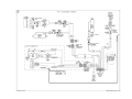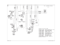
1
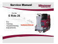
Service Manual
For the
E Ride 26
For:
Training
T bl h ti
Troubleshooting
Adjustments
Contents
1
2
3
4
•
•
•
•
•
5
•
•
6
7
8
•
Cautions -----------------------------------------------------------------------S f t Information
Safety
I f
ti ---------------------------------------------------------Technical Data---------------------------------------------------------------Maintenance Intervals------------------------------------------------------4.1 Customer Maintenance K-------------------------------------------K
4.2 Maintenance I after every 125 hours of operation----------4.3 Maintenance II after every 250 hours of operation---------4.4 Maintenance S after every 500 hours of operation,
minimum once per year---------------------------------------------------Squeegee Lift Mechanism-------------------------------------------------5.1 Squeegee Adjustment------------------------------------------------5 2 Squeegee Caster Adjustment--------------------------------------5.2
Adjustment
Disk Side Squeegee Adjustment ---------------------------------------Cylindrical Side Squeegee Adjustment--------------------------------Cylindrical Brush Replacement -----------------------------------------8.1 Cylindrical Brush Replacement -----------------------------------
Page 4
P
Page
5
Page 6
Page 8
Page 10
Page 11
Page 12
Page 13
Page 14
Page 15
Page 16
Page 18
Page 21
Page
g 22
Page 23
Page 2
Contents
9 Brush Pressure Setting ----------------------------------------10 Static Chains ------------------------------------------------------10 1 St
10.1
Static
ti Ch
Chain
i R
Rear ----------------------------------------11 Service Mode -----------------------------------------------------12 Changing Battery Types ---------------------------------------13 Solution Control --------------------------------------------------14 Trouble Shooting -------------------------------------------------•
14.1 Error Code Decal ------------------------------------------•
14.2 Error Codes -------------------------------------------------•
14.3 Error 8 --------------------------------------------------------•
14.4 Throttle Potentiometer ----------------------------------•
14.5 Mechanical --------------------------------------------------15 Lubrication Points ------------------------------------------------16 Carbon Brushes ---------------------------------------------------17 Circuit Breakers ---------------------------------------------------18 Electric Brake ------------------------------------------------------19 Wiring Diagrams --------------------------------------------------20 Notes-------------------------------------------------------------------
Page 24
Page 25
Page 26
Page 27
Page 28
Page 29
Page 30
Page 31
Page 32
Page 35
Page 36
Page 38
Page 39
Page 40
Page 41
Page 42
Page 44
Page 49
Page 3
1. Cautions
•
Caution:
•
Disconnect the A.C. Cord from the outlet and and D.C. Cord from
the battery pack before servicing the machine. Except for making
voltage and current measurements
measurements.
•
After any repair work test the machine for proper operation.
•
When servicing the machine always observe the general safety
and accident prevention guidlines.
Page 4
2. Safety Information
Page 5
3. Technical Data
Page 6
3. Technical Data
Page 7
4. Maintenance Intervals
•In a modular structure, the Minuteman System Maintenance determines the specific
t h i l proceedures
technical
d
tto b
be preformed
f
d and
d sets
t th
the titime iinterval
t
lb
between
t
th
the ttwo
maintenance cycles.
•For each of the maintenance cycle, the replaceable parts are determined as well.
Further details described in the specific chapters.
•Minuteman
Mi t
S
System
t
Maintenance
M i t
K:
K
To be performed by the customer (in daily or weekly intervals) according to the maintenance
and care instructions as specified in the operating instructions.
The operator must be professionally instructed after delivery of the machine by selling
d l
dealer.
•Minuteman System Maintenance I: (after every 125 hours of operation)
To be preformed by an authorized Minuteman Service Center in accordance with the
machine-specific system maintenance.
•Minuteman
Minuteman System Maintenance II: (after every 250 hours of operation)
To be preformed by an authorized Minuteman Service Center in accordance with the
machine-specific system maintenance.
•Minuteman System Maintenance S: (after every 500 hours of operation, safety check) To
be performed by an authorized Minuteman Service Center in accordance with the machine
machinespecific system maintenance.
Page 8
4.1 Maintenance Intervals
Record the maintenance intervals completed in the customers Operation
Manual, located in the battery compartment of the machine.
Page 9
4.2 Minuteman System Maintenance K
Page 10
4.3 Minuteman System Maintenance I
Page 11
4.4 Minuteman System Maintenance II
Page 12
4.5 Minuteman System Maintenance S
(Safety
(S
yC
Check))
Page 13
5. Squeegee Lift Mechanism
Side to Side Adjustment
The squeegee lift mechanism
Th
h i
lift
lifts and
d
lowers the squeegee assembly,
controls the parallel motion and pitch.
Jam Nuts (B)
Pre-adjust
j
the bars ((A)) to 151mm,, if
parts are being replaced. Loosen the
jam nuts (B) when adjusting the bar
(A). Tighten the jam nuts when done.
Make sure the squeegee lies evenly on
the floor. It should not tilt to one side.
Fine tune the bars (A) if necessary.
Pitch Adjustment (C)
Loosen jam nut and turn adjustment
bolt to set the pitch of the squeegee.
The rear squeegee blade should fold
evenly all the way across the bottom
edge
edge.
Pitch Adjustment (C)
Page 14
5.1 Squeegee Adjustment
Adjusting the Blades
Angle Adjustment
The angle adjustment is critical for insuring
that the squeegee blades lie evenly on the
floor.
1. Place the machine in the vacuum mode
and park the machine on a level surface.
2. Turn the machine off, while it is in vacuum
mode.
3 Loosen the jam nut on the adjustment
3.
screw.
• Note: Turning the screw counter clockwise
(Fig. A) will raise the ends and turning it
clockwise (Fig. B) will lower the center.
4. Adjust the squeegee using the adjusting
screw until the rear squeegee rubber rests
evenly on the floor all the way across the
floor.
5. Tighten the jam nut.
Page 15
5.2 Squeegee Adjustment
The clearance between the support roller and floor with squeegee unfolded
((Factoryy setting)
g) is: 0.1181099 Inches ± 0.01968498 inches ((3 mm ±0.5).
)
Note: Some floor surfaces may require adjusting the caster washers for optimum performance.
See following page.
3mm ± 0.5
0.118 in ± .02
Page 16
5.2 Rear Squeegee Adjustment
Page 17
7. Side Squeegee Adjustment
Step 1: Lower Scrub deck by placing
positioning arrow on “Double
Double Scrub”
Scrub
Double Scrub
Side Squeegee is flush with floor surface
Page 18
7. Side Squeegee Adjustment (Disk Models)
St 2:
Step
2 Loosen
L
b
both
th ffrontt and
d rear plastic
l ti kknobs.
b
Page 19
7. Side Squeegee Adjustment (Disk Models)
Step 3: Lower Side
squeegee so the squeegee
blade flairs at the bottom
around the bend and down
the straight edge.
•See the picture.
Step 4: Re-Tighten
Plastic Knobs.
Page 20
7. Side Squeegee Adjustment (Cyl. Models)
Cylindrical Models
Side Squeegees Adjustment
•Place
Place the machine in the “Double
Double
Scrub” mode.
•Loosen the two black knobs (B).
•The blade should be adjusted so
that it flairs on the bottom around
the corner and along the straight
edge.
•The side squeegees should also
flair
a out
outward
a d when
e ttraveling
a e g
straight forward.
•Tighten the black plastic knobs.
B
Accessing the Brushes
• Remove the yellow knob (C). The squeegee assembly will hinge open.
• The brush access plate (E) Is now accessible.
accessible
Page 21
8. Cylindrical Brushes
Side Squeegee Pivot
•Once the yellow knob has been removed.
•The side squeegee pivot (1) will swing open
allowing access to the brush access place
place.
•Remove the three black plastic knobs (2).
Cylindrical Brush Hub
•The access plate/Idler hub (3) can be
removed to access the brushes.
•The brushes may be removed without tools.
Brush access
plate/idler hub (3)
2
3
1
Page 22
8.1 Cylindrical Brush
Replacing the Cylindrical Brush
•Remove the access plate hub from the old brush.
•Discard the old brush.
•Stand the new brush on end with the slots on the
bottom.
bottom
•Press the Idler hub into the top end of the new
cylindrical brush.
•Slide the slotted the end of the brush deck first.
•Align
Align the slots of the brush with the drive pin and
push into the brush deck.
•Install the three plastic nuts.
•Rotate the brushes by hand, before tightening the
plastic nuts, to prevent the bristles from getting
caught between the housing and idler hub plate.
•Tighten the three plastic nuts.
•Close the squeegee pivot weldment and install the
yellow knob.
•Repeat the process on each side.
Page 23
9. Brush Pressure Settings
•The brush pressure range can be
changed when changing the type of
deck on the Hakomatic Scrubber
Dryer 100R models.
•Connect the orange/violet wire into
the terminal block with red/black wire
group for cylindrical decks and
unplug it for the disk or plate decks.
•The
The terminal block is located below
the controller on the operators left
side and below the seat behind the
metal panel.
Orange/Violet wire
Terminal Block
Brush current Settings
Connect the
orange/violet wire to
this group with the
red/black wires when
using
sing the ccylindrical
lindrical
brush decks.
Page 24
10. Static Chains
Static chains on the decks, must touch the floor, when the brush deck is in the down position.
They should be tested for continuity to the frame at each service interval
interval. Replace
Replace, if worn or
damaged. Failure to maintain the static chains may cause damage to the electronic controller.
Disk Decks
Cylindrical Decks
The static chain is attached to the motor
dh
hangs off
ff the
th rear side
id off th
the b
brush
h
and
deck.
The static chain on the cylindrical deck is
mounted on the side between the belt
cover and the brush access plate.
Page 25
10.1 Static Chain
•The Rear Static Chain
is located between the
two rear wheels.
•It should be present and
must always drag on the
floor.
•It should have continuity
to the frame.
Page 26
11. Service Mode
•The Service mode switch is located
on the operators right side behind
the metal panel below the seat.
•The Service mode switch can be
used to lower the deck when
servicing the brush deck assembly.
•Press and hold the lower side of
the switch for 15 seconds. The
d k will
deck
ill llower. P
Pressing
i th
the upper
side will raise the deck.
•The brush deck may be removed,
when it’s down for easier servicing.
g
•The controller will go back to
normal operation by turning the key
switch off .
Page 27
12. Changing Battery Types
•When changing from the wet lead acid type to gel or agm
batteries. The trio controller will need to be replaced
p
with p
part
number 748270, in order to obtain maximum run time. Gel
batteries can discharged to a lower voltage level than wet lead
acid batteries.
Trio Controller
•When changing from gel or agm to the wet lead acid batteries
The trio controller will need to be replaced with part number
748271, in order to obtain maximum life of the battery. Wet lead
acid batteries should not be discharged as low as gel and agm
types.
•The battery charger must match the type batteries that are being
used.
Page 28
13. Solution Control
•The
Th pump b
box iis llocated
t d th
the llower rear
area of the solution tank.
•Drain the recovery (dirty water) tank.
•Release the rubber latches on the recover
tank and tilt back to access the pump box.
Pump Box
•The
Th pump b
box iincludes
l d th
the solution
l ti filt
filter,
electric water solenoid and the water pump.
•The water volume is regulated by the
controller.
t ll
Th
The controller
t ll d
does thi
this b
by
adjusting the voltage to the pump.
•The operator can adjust the water level
with the 5k potentiometer on the dash
board.
Solution Control
Potentiometer
Page 29
14. Trouble Shooting (Electrical)
Trouble Shooting Electrical Problems on the E Ride 26
•
•
•
•
•
•
The E Ride uses a state of the art electronic circuitry with several diagnostic features. The battery
indicator serves two purposes. They are:
a. To display the charge status of the batteries on the LED display. This uses 10 LED bars,
for example: 10-lighted LED bars indicates a fully charged battery, 5-lighted LED bars, indicates
batteries are discharged 50%, 1-lighted LED indicates the batteries are discharged and so on.
b To display error codes for easier diagnosis of electrical problems
b.
problems. These are displayed by
flashing a quantity of LED bars in different sequences. The deferent flash sequences are as
follows:
Rippling: One LED bar lighted, then two LEDS, then three LEDS and so
on until all ten LEDS are lighted.
lighted Then it starts over
over.
Flashing Steadily: Flashing a set amount of LEDS for each error code on
and off steadily. The number of LEDS lighted indicates the type of error detected.
Flashing in Sequence: Flashing a set amount of LEDS for each error
C d iin a pulse
Code
l sequence. E
Example:
l Th
The ffour LEDS fl
flashes
h ttwo ti
times th
then pauses,
then it repeats itself.
Page 30
14.1 Error Code Decal
Page 31
14.2 Error Codes
Single flash Low Batteries
Batteries- Charge the batteries
Single flash Traction drive motor disconnected
Single flash - Brush motor disconnected
Single flash - Brush actuator overload
Two flash – Squeegee actuator overload
Page 32
14.2 Error Codes
Single flash – Vacuum motor disconnected
Single flash
flash- Off Isle Wand Activated
Si l flflashSingle
h Potentiometer
P
i
F
Fault
l
Single flash
flash- Control fault check all connections to
controller- see “Trouble Shooting the Code 8 Error”
Page 33
14.2 Error Codes
Si l flflashSingle
h Solution
S l ti ttank
k emptyt Riders
Rid
only
l
Five flash-Electric brake circuit fault- Check all connections to
the brake on the chassis drive.
Single flash- High battery voltage- Loose Connection
Check all connections between the batteries and the
controller, including the circuit breaker.
Ripple-Throttle activated during start up. If throttle pedal was
depressed during start up, release. If problem re-occurs:
Check throttle return springs for breakage. Check
potentiometer for fault or improper adjustment .
Page 34
14.3 Code 8 Error
1. Check for loose or burnt connections on the controller, batteries, cables and the circuit breaker.
g
2. Make the sure the circuit breaker is not damaged.
3. Measure the total battery voltage at the batteries and at the battery connections on the controller. They
should be exactly the same. A 1/10 of a volt or more difference would indicate a problem in the
connections.
4. Check to see, if the operator has recently washed the machine down and got water inside of the brush
motor or in the controller area.
5. Check for a disconnected or an open circuit or faulty potentiometer on the throttle or speed circuit.
Controller may not be detecting it in the circuit. Perform a continuity test. See “Testing the Potentiometer”
section.
6. Disconnect one motor connector from the Trio controller at a time and disconnect the batteries for 1 minute
and restart the machine.
machine If the code 8 disappears and is replaced by a different code
code, the circuit
disconnected should be considered suspect. For example the brush was disconnected. The code 8 is
replaced by code 3. Code 3 indicates the brush motor is disconnected.
7. Check for a loose or broken connection at the brush deck. Check to see if water has gotten inside the
brush motor. Check for a shorted motor.
8 Static electricity.
8.
electricity Check both the ground chains: there is one on the brush deck and one on the rear of the
machine. They should be contacting the floor. The one on the scrub deck should touch the floor only when
the deck is down. They also should have continuity between the end of the chain and the frame of the
machine. Repair or clean, if needed.
9. If everything checks OK, replace the Trio Controller.
Note controllers can be damaged by loose connections on inputs and outputs, static electricity and
water on electrical components such as on or in the controllers and motors.
Page 35
14.4 Throttle Potentiometer
•
Testing the Potentiometer
1.
2
2.
3.
4.
The throttle potentiometer resistance can be measured with an ohmmeter.
Unplug the throttle potentiometer at the connector next to itit.
Analog type meters are recommended for this test.
Measuring across the black and white wires on the potentiometer, the resistance should be zero
ohms with pedal on the riders in the neutral position in the full counterclockwise position. When the
pedal is moved to the full throttle position, in should be a smooth resistance change without dropping out.
It should measure 5K (5 thousand ohms) in the full position.
Measuring across the black and the red wire the resistance should be approximately 5K ohms (5
thousand), when in the neutral position.
When the pedal is at full throttle or the knob is full speed position, the resistance should drop to zero.
Loosen the n
nutt and scre
screw on the throttle arm and adjust
adj st if needed.
needed
It can also be tested at the P3 connector on the controller to insure a good connection to the controller.
Unplug the P3 connector from the controller. The throttle must be plugged into the harness while testing.
See below.
g the throttle to the full p
position,, the resistance should be smooth,, without dropping
pp g out
Note: when moving
for both tests. If the resistance does not go to 5K during the test, the arm and the potentiometer may
need to be adjusted to achieve it.
5.
6.
7
7.
8.
•
Page 36
14.4 Potentiometer
•
•
•
•
•
•
•
8. If they do not find a problem here, have them retest at the connector at the Trio controller. Reconnect the plug
at the throttle potentiometer.
9 U
9.
Unplug
l th
the P3 connector
t (Th
(The llarge white
hit connector)
t ) on th
the controller
t ll below
b l
the
th seat,
t b
behind
hi d th
the rear panel.l
10. Locate the black/orange and the black/pink wire.
11. Measuring across the black/orange and black/pink wires the resistance should be zero ohms in the neutral
position. It should be approximately 5k in the full throttle position. When the pedal is at full throttle the resistance
should drop to zero.
12. Measure across the black/pink and the black/white wires. The resistance should be approximately 5K (5
thousand) in the neutral position.
13. It should drop to zero ohms with the throttle in the full position.
14. If your reading is different with this test check all the connections between the controller and the throttle
control, including the seat switch.
black/white
black/pink
black/orange
Page 37
14.5 Trouble Shooting (Mechanical Problems)
Problem
Possible Causes
Solution
The brush puts down too much
pressure
Worn brushes
Replace the brushes if worn
The brush puts down too much
pressure
The belt is slipping or broken
(cylindrical models only)
Inspect the belt and bearings
Replace the belt, if broken or
pp g Replace
p
the bush
slipping.
bearings, if defective
The brush puts down too much
pressure
Only one brush is turning (disk models)
Replace the motor with the
gearbox
The brush puts down too much
pressure
The deck is tilted
Replace the bent lift linkages
The brush deck will not lift
Broken linkage, pins missing, actuator
is not working
Replace the defective or missing
parts
The brush deck is tilted
Bent linkage
Replace the bent linkage
Cylindrical brushes are worn
unevenly
Bent lift linkages or twisted brush
weldment
Replace the defective part
Page 38
15. Lubrication Points
L b i ti
Lubrication
Squeegee Mechanism Lubrication Points
Page 39
16. Carbon Brushes
•
•
•
•
Replace the carbon brushes on or before on the following:
Vacuum Motor at 1000 hours of operation
Brush Motors (all) at 2000 hours of operation
Chassis Drive Motor 3000 hours of operation
Page 40
17. Circuit Breakers
1
2
3
4
Breaker #
Description
1
100 Amp Main Circuit Breaker
2
3 Amp for Accessories Only
3
18 Amp Brush Motor 1 Cylindrical Only
4
18 Amp Brush Motor 2 Cylindrical Only
Note
Disk models do not have circuit breakers 3 and 4
Page 41
18. Electric Brake
• The chassis drive motor uses a electric brake system.
• The lever can be used to unlock the brake, in the event the machine can not move on
itit’ss own power
power. When the brake is released the machine will be easier to push
push.
• Pull lever away from the chassis drive motor to release. The lever will need to be
wedged to hold the brake in the released position. See the following page.
•The brake will automatically lock the chassis drive, when the lever is released.
•The brake will be electronically released
released, when the drive system is activated
activated.
Front of the machine
Lever
Pull the
lever
away
from the
motor to
release
and hold.
Page 42
18. Electric Brake
Wedging the Brake
•The brake can be
disengaged by
putting a wedge or a
small screwdriver
(shown) behind
lever arm to hold it
away from the brake
body.
•Use caution not to
force to the lever out
to far. Damage may
occur
occur.
•Do not leave the
lever permanently
wedged.
Small
Screw
Driver
Page 43
20. Notes
Page 49