1
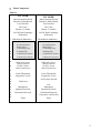
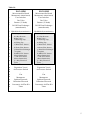
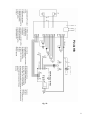
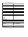
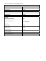
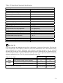
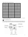
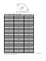
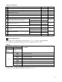
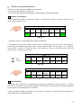
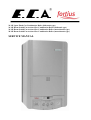
24 kW Open Flued Gas Combination Boiler (bithermic type)
24 kW Room Sealed Fan Assisted Gas Combination Boiler (bithermic type)
24 kW Room Sealed Fan Assisted Gas Combination Boiler (monothermic type)
28 kW Room Sealed Fan Assisted Gas Combination Boiler (monothermic type)
SERVICE MANUAL
CONTENTS
PRODUCT
Product Notation
Safety Systems
Technical Data
Main Components
Operating Functions
GAS TYPE CONVERSION
Gas Pressure Adjustments
Replacement Of The Burner Injectors
Jumper Adjustment
ADJUSTMENTS
Service Setting Mode
Chimney Sweep Push-Button PB4
FAULT & FAILURE
1
PRODUCT
Product Notation
Table 1
Notation
Description
FO 24 BB Fortius 24 kW Open Flued Gas Combination Boiler (bithermic type)
FO 24 HB Fortius 24 kW Room Sealed Fan Assisted Gas Combination Boiler (bithermic type)
FO 24 HM Fortius 24 kW Room Sealed Fan Assisted Gas Combination Boiler (monothermic type)
FO 28 HM Fortius 28 kW Room Sealed Fan Assisted Gas Combination Boiler (monothermic type)
Safety Systems
The safety systems in appliance provide entire safety for user and appliance. The safety systems are:
¾ Flue Gas Safety System
¾ Flame Failure Safety System
¾ Over-heat Safety System (105 0C)
¾ DHW (Domestic Hot Water) Over-heat Safety System (75 0C)
¾ CH (Central Heating) Over-heat Safety System (95 0C)
¾ High Water Pressure Protection System (3 bar)
¾ Low Water Pressure Protection System (0,8 bar)
¾ Low Voltage Protection System (185 VAC)
¾ Thermal Accumalation Protection System (with by-pass circuit and “pump over-run”)
¾ Frost Protection System (The appliance must be on stand-by mode to activate frost protection
system)
¾ Pump Anti-sieze Function
¾ 3 Way Anti-sieze Function (in monothermic types)
¾ Automatic Air Vent
¾ Expansion Vessel
¾ DHW safety stop function
Technical Data
Fortius 24 kW open flued gas combination boiler (FO 24 BB) is B type boiler (DIN EN 297). B
type boilers have an open combustion chamber. Combustion air is provided from the installation
room and products of combustion is discharged by means of approved flue ducts connections and a
chimney. Therefore, they are named as room air dependent gas appliances.
Fortius 24 / 28 kW room sealed fan assisted gas combination boilers (FO 24 HB, FO 24 HM, FO
28 HM) are C type boilers (DIN EN 483). C type boilers have a sealed combustion chamber.
Required fresh air for combustion is provided independently from the installation room by
concentric air/flue ducts and products of combustion can be also discharged by the same air/flue
ducts. Therefore, they are named as air independent gas appliances.
2
Table 2
FO 24 BB
FO 24 HB
FO 24 HM
FO 28 HM
Gas Category*
Boiler Type
Type of gas
II 2H 3+
B 11 BS
Natural gas
LPG
II 2H 3+
C12x, C32
Natural gas
LPG
II 2H 3+
C12x, C32
Natural gas
LPG
II 2H 3+
C12x, C32
Natural gas
LPG
Performances
Pmin, Min. Heat Output
Pmaks, Max. Heat Output
P%80, Heat Output
Qmin, Min. Thermal Load
Qmaks, Max. Thermal Load
Q%80, Thermal Load
8,4
24
19,2
9,3
26,6
21,3
8,4
24
19,2
9,2
26,2
21
8,4
24
19,2
9,2
26,2
21
9,8
28
22,4
10,7
30,6
24,5
kW
kW
kW
kW
kW
kW
Gas Consumption**
Natural Gas (Max. Load)
Natural Gas (Min. Load)
LPG
2,77
0,97
2,08
2,73
0,96
2,08
2,73
0,96
2,08
3,19
1,12
2,39
m3/h
m3/h
kg/h
20
28 / 37
20
28 / 37
20
28 / 37
20
28 / 37
mbar
mbar
Max. Flow Rate
Min. Operating Pressure
Max. Operating Pressure
Set Temperature Range
3
10 (∆t=34)
0,3
10
35-60
3
10 (∆t=34)
0,3
10
35-60
3
10 (∆t=34)
0,3
10
35-60
3
12 (∆t=33)
0,3
10
35-60
ltr/min
ltr/min
bar
bar
o
C
Central Heating
Min. Operating Pressure
Max. Operating Pressure
Set Temperature Range
0,8
3
40-80
0,8
3
40-80
0,8
3
40-80
0,8
3
40-80
bar
bar
o
C
230V AC- 50Hz
230V AC- 50Hz
230V AC- 50Hz
230V AC- 50Hz
105
8
750x454x340
33,7
150
8
750x454x340
39,8
150
8
750x454x340
40,8
150
8
750x454x340
41,3
V AC/Hz
Gas Supply Pressure
Natural Gas
LPG
Unit
Domestic Hot Water
Min. Flow Rate For Activating***
General
Electrical Supply
Electrical Power Consumption
Expansion Vessel
Dimensions (HxWxL)
Weight (Net)
watt
ltr
mm
kg
**For gas consumption calculation ; Natural gas: Hu=9,59 kWh/m3
LPG: Hu=12,793 kWh/kg
*** DHW ON flow rate can be adjustable as 3 ltr/min (default) or 3,5 ltr/min.
*the following gas categories can also be used
Gas Categories
FO 24 BB
FO 24 HB
FO 24 HM
FO 28 HM
II 2H 3B/P
II 2E 3B/P
II 2H 3B/P
II 2E 3B/P
II 2H 3B/P
II 2E 3B/P
II 2H 3B/P
II 2E 3B/P
3
Main Components
Table 3a
1
2
3
4
5
6
FO 24 BB
FO 24 HB
Microcontroller Board
Bitermic (Main Board)
User Interface
Gas Valve
Burner (13 blade)
24 kW Heat Exchanger
(bithermic)
Microcontroller Board
Bitermic (Main Board)
User Interface
Gas Valve
Burner (13 blade)
24 kW Heat Exchanger
(bithermic)
Hydroblock (bithermic)
Hydroblock (bithermic)
7
a) Pump
a) Pump
8
9
b) 3 Bar Pressure
Relief Valve
c) Discharge Tap
b) 3 Bar Pressure
Relief Valve
c) Discharge Tap
10
d) Filling Tap
d) Filling Tap
11
e) Water Pres. Sensor
e) Water Pres. Sensor
12
f) Water Flow Sensor
f) Water Flow Sensor
13
-
-
14
DHW NTC Sensor
(Surface Mount)
CH NTC Sensor
(Direct Immersion)
DHW NTC Sensor
(Surface Mount)
CH NTC Sensor
(Direct Immersion)
16
-
-
17
19
Limit Thermostat
Expansion Vessel
-
20
TTB Sensor
21
Manometer
Ignition Electrode
Ionization Electrode
Timer
Limit Thermostat
Expansion Vessel
Air Pressure Switch
Fan
Manometer
Ignition Electrode
Ionization Electrode
Concentric Air/Flue Kit
Timer
15
18
22
23
24
25
26
4
Table 3b
1
2
3
4
5
6
FO 24 HM
FO 28 HM
Microcontroller Board
Monotermic (Main Board)
User Interface
Gas Valve
Burner (13 blade)
24 kW Heat Exchanger
(monothermic)
Microcontroller Board
Monotermic (Main Board)
User Interface
Gas Valve
Burner (15 blade)
28 kW Heat Exchanger
(monothermic)
Hydroblock (monothermic)
Hydroblock (monothermic)
7
a) Pump
a) Pump
8
9
b) 3 Bar Pressure
Relief Valve
c) Discharge Tap
b) 3 Bar Pressure
Relief Valve
c) Discharge Tap
10
d) Filling Tap
d) Filling Tap
11
e) Water Pres. Sensor
e) Water Pres. Sensor
12
f) Water Flow Sensor
f) Water Flow Sensor
13
g) Plate Heat Exchanger
(12 plate)
h) DHW NTC Sensor
(Direct Immersion)
ı) CH NTC Sensor
(Direct Immersion)
j) 3 Way Electrical
Valve
g) Plate Heat Exchanger
(14 plate)
h) DHW NTC Sensor
(Direct Immersion)
ı) CH NTC Sensor
(Direct Immersion)
j) 3 Way Electrical
Valve
14
15
16
17
18
19
20
21
22
23
24
25
26
Limit Thermostat
Expansion Vessel
Air Pressure Switch
Fan
Manometer
Ignition Electrode
Ionization Electrode
Concentric Air/Flue Kit
Timer
Limit Thermostat
Expansion Vessel
Air Pressure Switch
Fan
Manometer
Ignition Electrode
Ionization Electrode
Concentric Air/Flue Kit
Timer
5
1 MICROCONTROLLER BOARD (MAIN BOARD)
The main board operates on 230 VAC, 50 Hz and drives gas valve, fan, pump and (in monothermic
types) 3 way electric valve. Dynamic air pressure test takes place before every ignition cycle. Limit
thermostat ensures extra safety level. Flame in the burner is checked regularly.
The main board provides all the functionality and safety of the boiler. The board was cased by a
plastic casing, which was mounted on the gas valve. The functionality of the board is provided with
2 microcontrollers (low voltage and high voltage microcontroller).
The board can be divided in 2 part: low voltage side and high voltage side. Both side have a
microcontroller. There is continuous communication between microcontrollers. Numerous data is
sent from one side to the another for check and comparison.
6
Wiring Diagrams
fig. 1a
7
fig. 1b
8
fig. 1c
9
Tablo 4 Technical and Functional Specifications
General
Power supply range:
230 Vac -15% +10%
Power supply frequency:
50 Hz ± % 2
Power consumption:
5 VA
Max. admitted humidity:
90% @ 40 °C (non condensing)
Working temperature range:
-20 °C … 60 °C
Electrical rating
Fusing:
2A
Fan output:
230 Vac 0.8 A maks, cosϕ ≤0.6
Pump output:
230 Vac 0.8 A maks, cosϕ ≤0.6
3-Way valve output (1):
230 Vac 0.8 A maks, cosϕ ≤0.6
3-Way valve output (2):
230 Vac 0.8 A maks, cosϕ ≤0.6
Total output:
2A
Gas valve output:
230 Vrac, 50mA
Diferantial air pressure switch input:
12 Vdc, 100 kOhm
Limit thermostat input:
5 Vdc, 100 kOhm
Water pressure switch input:
12 Vdc, 100 kOhm
Water flow sensor input & output:
Sensors input:
- CH sensor
- DHW sensor
- TTB sensor
12 ± 4 Vdc, 10 mA max.
Communication input:
Communication output:
10 kOhm NTC
“0” p 0,8 Vdc
“1” + 2 … 24 Vdc (10 Ohm)
24 V and 10 mA max.
User interface connectors
High voltage spark:
2,8 x 0,5 mm spade terminal (2 pieces)
Flame sensing:
4,8 x 0,5 mm spade terminal
Mains connector:
10 pole Molex Minifit (male)
Low voltage connectors:
16 and 6 pole Molex Microfit (male)
Flame sensing
Response time ON:
< 0,2 sec
Response time OFF:
< 1 sec
10
Tablo 4 Technical and Functional Specifications
Timing
Pre purge time:
0 sec
Waiting time:
0 sec
Pre ignition time:
2 sec
Safety time:
7 sec
Number of retrials:
5
Flame failure response time:
1 sec
Post ignition time:
0,4 sec
Post purge time:
0,8 sec
Pump over-run time:
A) for DHW
- Monothermic&Winter mode
- Monothermic&Summer mode&3 way electric valve
- Bithermic& Winter mode
- Bithermic& Summer mode
B) for CH
- Winter mode
- Summer mode
3 sec
5 sec
3 sec
TCH > 75 °C: 1 sec
TCH < 75 °C: 0 sec
10 min
5 sec
Pump anti-seize run time:
A) Bithermic type
5 sec
B) Monothermic type
5 sec
CH anti-cycling time:
3 min (0 min … 15 min)
TTB error waiting time:
15 min
Chimney sweep run time:
20 min
Timing tolerance:
± 5%
11
Tablo 4 Technical and Functional Specifications
Other Specifications
Nr. of electrodes:
2 for flame ignition and one for detection
Flame sensing cable and spark cable:
max. 0,5 m
External components (except heat demand):
max 0,5 m
Remote reset:
max. of 5 reset in 15 minutes
CH water SET temperature range:
40 °C … 80 °C
CH water OFF temperature:
CH water SET temperature + 10 °C
CH water ON temperature:
CH water SET temperature
DHW water SET temperature range :
35 °C … 60 °C
DHW water OFF safety temperature:
75 °C
DHW ON Flow rate :
3,0 lt/min
DHW OFF Flow rate :
2,5 lt/min
Frost protection level 1 ON temperature:
8 °C (pump runs)
Frost protection level 1 OFF temperature:
10 °C (pump is OFF)
Frost protection level 2 ON temperature:
6 °C (burner runs)
Frost protection level 2 OFF temperature:
30 °C (burner is OFF)
Limit thermostat OPEN temperature:
105 °C
Limit thermostat CLOSE temperature:
75 °C
TTB sensor limit temperature (in the first 90 sec)
100 °C
TTB sensor limit temperature (after the 90 sec)
70 … 95 °C
2 GAS VALVE
Gas valve controls and modulates the gas flow to the burner. It consists of two valves: The first one
is the on/off safety valve and the second one is the main (modulation) valve which enables safety
and modulated gas control. Maximum and minimum operating pressures can be adjusted
mechanically on the gas valve. Maximum outlet pressure can be adjusted with the adjustment screw
of the maximum pressure regulator. Minimum outlet pressure can be adjusted with the mechanical
minimum adjustment screw (see Gas pressure adjustment, page 30).
Table 5 Gas Valve
Natural Gas Max. pressure setting (factory default)
(mbar)
Min. pressure setting (factory default)
Max. pressure setting (factory default)
LPG
(mbar)
Min. pressure setting (factory default)
Gas inlet & outlet connections
24 kW Models
11,2
1,3
28 / 35
3,3 / 4,1
G ¾”
28 kW Models
11,3
1,2
28 / 35
3,4 / 4,2
G ¾”
(External thread) (External thread)
12
fig. 2 Gas Valve
3
BURNER
The gas coming from the gas valve is fired in the burner. 13 blade burners are used in 24 kW boilers
while 15 blade burners are used in 28 kW boilers. Some of the common specifications of these two
burners are shown in the table below.
Table 6 Burner
∅ 1,25 mm
∅ 0,75 mm
G ¾” (External thread)
Injector (nozzle) diameter for natural gas
Injector (nozzle) diameter for LPG
Gas inlet connection
fig. 3 Burner
13
4
HEAT EXCHANGER
Heat exchanger is the component which enables transferring the energy produced by the burning of
the gas to the water circuit. Different heat exchangers are used in bithermic (24 kW) and
monothermic (24 / 28 kW) models. In bithermic heat exchangers which have two water inlets and
two water outlets, both central heating and domestic hot water circuits are heated. In monothermic
types, the exchanger has only one water inlet and one water outlet and only the central heating
circuit is heated. In monothermic types, domestic hot water circuit is heated by a second exchanger
(plate-heat exchanger).
In both heat exchangers, there is a manual air vent on central heating inlet.
Table 7 Heat Exchanger
Bithermic heat exchanger (24 kW)
Central heating inlet & outlet connections
Domestic hot water inlet & outlet connections
Monothermic heat exchanger (24 kW)
Water inlet & outlet connections
Monothermic heat exchanger (28 kW)
Water inlet & outlet connections
G ¾” (External thread)
G ½” (External thread)
G ¾” (External thread)
G ¾” (External thread)
fig. 4a Bithermic Heat Exchanger
14
fig. 4b Monothermic Heat Exchanger
5
HYDROBLOCK
Two different types of hydroblocks are used in bithermic and monothermic types. Hydroblock
consists of different components depending on the boiler model. The bithermic hydroblock has
pump, pressure relief valve (3 bar), discharge tap, filling tap, water pressure switch and water flow
sensor on it. The monothermic hydroblock has pump, pressure relief valve (3 bar), discharge tap,
filling tap, water pressure switch, plate heat-exchanger, water flow sensor, domestic hot water
(DHW) sensor, central heating (CH) sensor and 3 way electric valve on it. On both hydroblocks,
inlet and outlet manifolds are connected by a by-pass pipe.
15
fig. 5a Bithermic Hydroblock
1 Outlet manifold
2 Inlet manifold
3 By-pass pipe
4 Water flow sensor
5 Filling tap
6 Gasket (G3/4” & G1/2”)
7 Hall effect sensor
16
fig. 5b Monothermic Hydroblock
1 3 way electric valve
2 Inlet manifold
3 By-pass pipe
4 Water flow sensor
5 Filling tap
6 Valve motor
7 Valve motor clip
8 Hall effect sensor
9 Bolt
10 Oring
11 By-pass pipe clip
17
6
PUMP
Pump enables the central heating water circulation in monothermic and bithermic types. Also in
monothermic types, it enables heating the domestic water passing through the plate heat-exchanger
by causing the central heating water short circuit circulation.
Pump is located on the hydroblock and has 3 speed stages. The pump has expansion vessel and
termomanometer connections and also an automatic air vent on it.
fig. 6 Pump
Table 8 Pump
Maximum Power
Speed Stages
Hydroblock connection (pump water inlet)
Pump water outlet connection
Termomanometer connection
Expansion vessel connection
85 W
3
Rapid connection (O-ring)
G ¾” (External thread)
Rapid connection (O-ring)
Rapid connection (O-ring)
fig. 7 Pump’s Characteristic Curve (Height & Flow)
18
7
PRESSURE RELIEF VALVE (3 BAR)
Pressure relief valve (3 bar) protects the central heating circuit and the appliance against increasing
pressure. When the pressure in the central heating circuit is over 3 bars, the relief valve functions
and decreases the pressure (the outlet tap of the 3 bar relief valve should be connected to the drain
line with a plastic hose). The pressure relief valve is on the hydroblock, on the central heating
return.
Table 9 Pressure relief valve
Hydroblock connection
Water discharge pipe connection
Rapid connection (O-ring)
G ½”
fig. 8 Pressure Relief Valve
8 DISCHARGE TAP
The discharge tap is used for removing the water in the central heating circuit. It is on the outlet
manifold in bithermic types while it is on the inlet manifold in monothermic types.
Table 10 Discharge Tap
Hydroblock connection
G ¼” (External thread)
9 FILLING TAP
The filling tap is for filling the central heating circuit using the domestic water line. It is integrated
on the inlet manifold of the hydroblock.
10 WATER PRESSURE SWITCH
Water pressure switch prevents the operation of the appliance in low water pressure. If the water
pressure in the central heating circuit is below 0.8 bar, the water pressure switch goes OFF and the
signal sent from the water pressure switch to the main board prevents the boiler operation. When
the pressure is above 1 bar, the boiler goes back to normal operation. The water pressure switch is
on the outlet manifold of the hydroblock, on the central heating flow.
The electric circuit connection of the water pressure switch is COM and CO terminals (NC not
connected).
TABLE 11 Water Pressure Switch
Hydroblock connection
G ¼” (External thread)
19
fig. 9 Water Pressure Switch
11 PLATE HEAT-EXCHANGER
Plate heat-exchanger is the secondary heat-exchanger used in monothermic types for heating the
domestic water. In need of domestic hot water, the 3 way electric valve sends the central heating
water from the primary heat-exchanger to the plate heat-exchanger. Heat of the central heating
water is transferred to the domestic water in the plate heat-exchanger. 12 plate type are used in 24
kW boilers while 14 plate type are used in 28 kW boilers. The plate heat-exchanger is mounted
using two bolts on the monothermic hydroblock. Leakage in the inlet and outlet of central heating
and domestic hot water circuits is prevented using O-rings.
Table 12 Plate Heat-Exchanger
Hydroblock connection
Plate heat-exchanger water inlet & outlet onnections
Bolts (2 pieces)
O-rings (4 pieces)
fig. 10 Plate Heat-Exchanger
12 WATER FLOW SENSOR
The water flow sensor measures the domestic hot water flow rate. It is integrated in the inlet
manifold of the hydroblock in both bithermic and monothermic types.
A turbine in the water flow sensor rotates during flow and supports a magnet. The turbine creates a
magnetic field. The hall effect sensor reacts to the magnetic field and sends data to the main board.
The main board controls the domestic hot water delivery according to the flow rate values delivered
from the water flow sensor. When the water flow rate reaches 3 lt/min, domestic hot water delivery
begins. When the rate is below 2.5 lt/min, domestic hot water delivery is stopped.
The hall effect sensor is on the water flow sensor and can be easily mounted or removed.
20
fig. 11 Water Flow Sensor
13 CENTRAL HEATING AND DOMESTIC HOT WATER (NTC) TEMPERATURE
SENSORS
The central heating and domestic hot water temperature sensors are NTC (Negative Temperature
Coefficient) type. In NTC sensor, temperature and sensor resistance are inversely proportional; the
sensor resistance decrease as temperature increases and vice versa. NTC sensors are usually defined
by their nominal resistance at 25°C, but this value does not completely define the nominal R-T
curve of the NTC. The R-T relation of the NTC sensors used in our appliances are shown in Table 14.
Temperature sensors measures the temperature of the central heating and domestic hot water and
send signals to the main board. Two types of temperature sensors are used in bithermic types,
surface mounted sensors for domestic water and direct immersion sensors for central heating. Only
direct immersion NTC sensors are used in monothermic types.
In bithermic models, the surface mounted temperature sensor is directly mounted on the domestic
water delivery (outlet) pipe and the direct immersion temperature sensor is mounted on the central
heating flow of the heat-exchanger. In monothermic types, the direct immersion temperature
sensors (CH & DHW) are mounted on the outlet manifold of the hydroblock (3 way electric valve).
Central heating circuit over-heat safety (electronic limit - 95°C) is secured by the central heating
NTC sensor and domestic water over-heat safety (electronic limit - 75°C) is secured by the
domestic water NTC sensor.
Table 13 NTC Temperature Sensors
Surface mounted temperature sensor connection
Direct immersion temperature sensor connection
a) surface mount
With Klips
1/8” (external thread)
b) Direct immersion
fig. 12 NTC Temperature Sensors
21
Table 14 The R-T relation of the NTC sensors
T (oC) Temperature
-20
-10
0
10
20
25
30
40
50
60
70
80
85
90
100
110
120
125
R (Ω) Resistance
98660
56250
33210
20240
12710
10170
8194
5416
3663
2530
1782
1278
1089
931,6
690,0
518,5
395,0
346,4
α (1/oC) Sensitivity
-5,8 %
-5,4 %
-5,1 %
-4,8 %
-4,5 %
-4,4 %
-4,3 %
-4,0 %
-3,8 %
-3,6 %
-3,4 %
-3,2 %
-3,2 %
-3,1 %
-2,9 %
-2,8 %
-2,7 %
-2,6 %
The sensitivity α is the percentage change in resistance of the sensing element per oC temperature
change at the specified temperature.
14 3 WAY ELECTRİC VALVE
3 Way electric valve sends the central heating water coming from the main heat-exchanger to the
plate heat-exchanger when domestic hot water is needed in monothermic models. When there is no
more need for domestic hot water, valve gets back to its previous position enabling central heating.
fig. 13 3 Way Electric Valve
22
15 LIMIT THERMOSTAT
The limit thermostat used is bimetal type. When water CH from the heat-exchanger exceeds 105°C,
the limit thermostat opens and cuts the signal sent to the main board and ensures safety. When the
water temperature is below 75 °C, the limit thermostat closes enabling the boiler to operate again
after the reset. In bithermic types, limit thermostat is mounted on the heat-exchanger with a metal
clip while in monothermic types it is mounted using two screws.
fig. 14 Limit Thermostat
16 EXPANSION VESSEL
Expansion vessel covers the expansion of water in the central heating circuit which is a closed
circuit.
Table 15 Expansion Vessel
Expansion Vesssel Volume
Water Inlet Connection
8 liters
G ½” (external thread)
fig. 15 Expansion Vessel
23
17 DIFFERENTIAL AIR PRESSSURE SWITCH (APS)
Differential air pressure switch is used in room sealed fan assisted models. It controls the air flow
by measuring the pressure differences of the clean air required for burning and flue gas. In case of
problems like blockage in the air/flue kit or a strong outer air flow, the air pressure switch shuts
down the boiler. The low pressure inlet of the differential air pressure switch is connected to the fan
with a silicon hose. The high pressure inlet is connected to the combustion body again with a silicon
hose.
When the boiler is started, the differential air pressure switch is already open. The fan operates, and
after a certain period of time, when the pressure difference is above the predefined value the switch
closes and the boiler begins operating. When the pressure difference is under certain value, the
switch opens and prevents the operating of boiler.
The electric circuit of the differential air pressure switch is connected to terminals (1) and (3) (2 not
connected).
Table 16 Differential Air Pressure Switch
Interior diameter of silicon hose to fan
Interior diameter of silicon hose to combustion body
5 mm
5 mm
Low pressure inlet (P2)
High pressure inlet (P1)
fig. 16 Differential Air Pressure Switch
18 TTB TEMPERATURE SENSOR
The TTB temperature sensor is an NTC sensor like the central heating and domestic water
temperature sensors. The R-T relation of the sensor is shown in Table 17.
TTB temperature sensor measures the temperature of the flue gas in open flued boilers. If the flue
gas temperature exceeds the limit value because of blockage in the flue system or insufficient
chimney draught, the TTB sensor shuts down the boiler by sending a signal to the main board and
the boiler can not be started for 15 minutes. The TTB temperature sensor is mounted to hood using
two screws.
The TTB temperature sensor limit value differs according to operating capacity.
a) In the first 90 sec., TTB sensor limit temperature is 100°C.
b) After the 90 sec. of start up period, the limit temperature is between 75 - 95 °C depending on the
boiler capacity.
24
fig. 17 TTB Temperature Sensor
Table 17 The R-T relation of the TTB sensor
T (oC) Temperature
-20
-15
-10
-5
0
5
10
15
20
25
30
35
40
45
50
55
60
65
70
75
80
85
90
95
100
105
110
115
120
125
130
R (Ω) Resistance
97060
72940
55319
42324
32654
25396
19903
15714
12493
10000
8056
6530
5327
4370
3603
2986
2488
2083
1752
1480
1255
1070
915
787
680
592
517
450
390
340
300
α (1/oC) Sensitivity
-5,8 %
-5,6 %
-5,4 %
-5,3 %
-5,2 %
-5,1 %
-4,8 %
-4,7 %
-4,5 %
-4,4 %
-4,3 %
-4,2 %
-4,0 %
-3,9 %
-3,8 %
-3,6 %
-3,6 %
-3,5 %
-3,4 %
-3,3 %
-3,3 %
-3,3 %
-3,2 %
-3,1 %
-3,0 %
-2,9 %
-2,8 %
-2,7 %
-2,6 %
-2,6 %
-2,5 %
The sensitivity α is the percentage change in resistance of the sensing element per oC temperature
change at the specified temperature.
25
19 FAN
Fan enables taking the clean air required for combustion to the combustion chamber and disposing
of flue gas in room sealed fan assisted boilers.
Table 18 Fan
Maximum Power
Interior diameter of silicon hose connected to APS
55W
5 mm
fig. 18 Fan
20 TERMOMANOMETER
Termomanometer displays the water temperature and water pressure of the central heating circuit.
21 IGNITION ELECTRODE
The burner is ignited by a spark between two ignition electrodes. One of the electrodes is earthed. A
1k resistor is attached on the cable of one of the electrodes against the oscillations caused by EMC.
22 IONIZATION ELECTRODE
Ionization electrode checks whether there is fire in the burner or not by creating a current and
sending data to the main board during burning process.
26
MODES OF OPERATION
a) Stand-by Mode: when there is no heat demand for central heating or domestic hot water.
b) Domestic Hot Water (DHW) Mode: when there is need for DHW (hot water tap is opened), the
hall effect sensor on the water flow sensor detects the water flow and signals the main board for
DHW delivery.
c) Central Heating (CH) Mode: can be activated in two ways:
- Rotate the CH potentiometer (P1 potentiometer) to the winter mode.
- Internal frost protection requests heat.
d) Frost Protection: It automatically functions according to the water temperature values detected
by CH and DHW temperature sensors in order to protect the water circuits against freezing. The
ON/OFF switch should be in ON position for frost protection system to activate.
e) Service Settings Mode: This mode can be activated by pushing the PB3 service button on the
control panel and is used for boiler settings.
f) Fault/Error Conditions: like sensor faults or over temperature.
The priority of the modes of functions is as follows:
1. Fault/Error Condition
2. Service Settings Mode
3. DHW Mode
4. CH Mode
5. Frost Protection
6. Stand-By Mode
If there is no error or fault, service settings have the highest priority. For example in case of an over
heating condition, the system should reach normal temperature conditions before service settings
mode can be activated.
1 Stand-by Mode
In stand-by mode, the pump does not function (if the pump over-run time is finished), the burner
and the gas valve are OFF.
2 Domestic Hot Water
If there is no error condition and the water flow detected by the hall effect sensor is enough, the
boiler will supply domestic hot water. DHW mode starts when the flow rate reaches 3 lt/min. and
ends when flow rate is less then 2.5 lt/min. The flow sensor has a flow limiter in it. Flow rate is
limited to 10 lt/min. in 24 kW models and 12 lt/min. in 28 kW models.
¨ DHW Mode Control Variables:
- DHW potentiometer (P2 potentiometer)
- Water temperature detected by DHW temperature sensor
- Water flow rate
27
- Domestic hot water can be obtained between 35°C and 60°C.
- Domestic hot water safety temperature is 75°C. If the temperature detected by DHW sensor is
above 75°C, DHW operation will stop (burner goes off).
- DHW operation is possible even if CH anti-cycling time is active.
- During DHW operation, min.-max. running mode selection is not possible with PB4 button (see
page 39) in both bithermic and monothermic types.
¨ DHW priority cancellation function
DHW mode has priority over CH mode, but monothermic type boilers have DHW priority
cancellation zone. The cancellation zone is between 30 oC and 35 oC on the DHW potentiometer. In
DHW priority cancellation zone, it is not possible to have domestic hot water even if hot water tap
is open. And the 3 way electric valve remains open to CH circuit.
¨ DHW safety stop function
if DHW mode is active for a period longer than 60 min., DHW mode will stop automatically except
for winter operation in bithermic types, and the boiler will operate depending on system
configuration:
a) In Monothermic types
- if the boiler is in summer mode, the burner will switch OFF, and to reactivate DHW mode again, it
is necessary to close the hot water tap and open it again.
- if the boiler is in winter mode, winter mode will be active until closing the hot water tap and open
it again.
b) In Bithermic types
- if the boiler is in summer mode, the burner will switch OFF, and to reactivate DHW mode again, it
is necessary to close the hot water tap and open it again.
- if the boiler is in winter mode, DHW safety stop function wiil not be active.
¨ DHW mode frost protection
In stand-by mode, if the DWH temperature sensor detects temperature less then 6°C, CH mode is
activated (burner starts). As long as frost protection conditions last (till water temperature reaches
30°C) the burner operates in minimum capacity. When the water temperature reaches 30°C, burner
goes off.
3
Central Heating Mode
The pump operates as long as the CH mode is active. When CH mode ends (and there is no DHW
demand), pump stops after pump over-run time. This condition is valid when the boiler is in pump
control mode 1 or pump control mode 2 and the room thermostat is connected. If the boiler is in
pump control mode 2 and the room thermostat is not connected, the pump will start operating when
the boiler is switched ON and will operate until switched OFF or a CH circuit low water pressure
error occurs or until there is DHW demand in bithermic models.
If DHW mode is activated in the pump over-run time following the CH mode, pump over-run time
is not completed. This prevents the hot water from going to CH circuit.
¨ CH Mode Control Variables:
- CH potentiometer (P1 potentiometer)
- Water temperature detected by CH temperature sensor
- Hystherisis (10 °C)
28
- When there is CH demand, ignition starts and ignition state continues until flame is present.
- When the ignition state is over, the boiler will operate in normal modulation and reach the set
point within the time defined with slope (°C/min). After that, modulation continues.
- If the central heating water temperature exceeds 95°C in CH mode, over temperature error
(electronic limit) occurs and the boiler will remain in this error mode till water temperature drops to
a safe level (80°C). Pump keeps working in the over temperature error condition. When the
temperature drops, the boiler continues normal operation. This is a safety measure and should not
normally occur because when the water temperature exceeds the value set by the user plus
hystherisis ( max.80°C +10°C), the burner will go off.
- Water temperature interval in CH mode is 40°C - 80°C.
¨ Outside temperature control (OTC) option
The boiler (CH mode) can operate depending on outside temperature if a OTC sensor is connected
to heating system. The pump has no over-run time.
- OTC has priority over room thermostat (if present).
- OTC function is only active when the boiler is in winter mode.
¨ CH mode frost protection
In stand-by mode, if the CH temperature sensor detects temperature less then 6°C, CH mode is
activated (burner starts). As long as frost protection conditions last (till water temperature reaches
30°C) the burner operates in minimum capacity. When the water temperature reaches 30°C, burner
goes off.
4 Pump Behaviour
The pump functions differently depending on the boiler operating modes.
¨ In Stand-by Mode:
The pump does not normally work in stand-by mode. The pump will function in the following
conditions:
- In pump over run time
- If the temperature detected by the CH sensor is over 85°C, the pump will keep running till water
temperature drops to 80°C.
- Frost protection level 1: If the temperature detected by the CH sensor is below 8°C, the pump will
start running and keep running till the temperature reaches 10°C.
- In case of an error condition pump will switch on except low water pressure error which will
prevent the pump from dry running.
Exceptional Situation: The pump will run permanently in stand-by mode if the boiler is in pump
control mode 2 and the room thermostat is not connected.
¨ In DHW Mode:
In monothermic types, when DHW mode begins, pump will run as in the CH mode (In bithermic
types, pump does not run in DHW mode). After DHW mode ends, pump behaviour depends on
system configuration:
- Monothermic & Winter Mode: pump runs for the defined over run time (3sec).
- Monothermic & Summer Mode & 3 Way Electric Valve: pump will run for 5 sec. more.
29
- Bithermic & Winter Mode: pump runs for the defined over run time (3sec). This is for transferring
the remaining energy to the CH circuit.
- Bithermic & Summer Mode: if the temperature detected by the CH temperature sensor is more
then 75°C, the pump will run for 1 sec., otherwise it will not run.
¨ In CH Mode:
- Pump always runs when CH mode is active. After the CH mode is ended, the pump will run for
the defined period of time (10 min.)
- If the boiler is switched to summer mode when CH mode is active, pump over run time is 5 sec.
5 Pump Anti-Seize Function
The pump may be blocked if not used for a long period of time. To prevent this, 24 hours after the
pump has run for the last time, it is run for 5 sec. in CH mode.
6
3 Way Anti-Seize Function
In monothermic models, 3 way valve blocking protection becomes active with pump blocking
protection and changes position to prevent blocking.
7 Fault/Error Conditions
Fan does not run in lock out and blocking conditions. Pump will not run only in low water pressure
condition.
30
GAS TYPE CONVERSION
: Gas type conversion from LPG to natural gas or from natural gas toLPG
must be carried out only by qualified person.
- Gas type conversion can be divided in 3 sections: gas pressure adjustments, replacement of the
burner injectors and jumper adjusment.
Gas Pressure Adjustments
The operating pressure varies depending on the type of gas. Therefore, minumum and maximum
operating gas pressure must be set by means of the adjusment screws that are on top of the gas
valve. The heat output directly depends on the operating pressure. When the operating gas pressure
range is adjusted, minimum and maximum heat output is also adjusted (mechanically).
24 kW Models
28 kW Models
Max. operating gas pressure (mbar)
11,2
11,3
Min. operating gas pressure (mbar)
1,3
1,2
Max. operating gas pressure (mbar)
28 / 35
28 / 35
Min. operating gas pressure (mbar)
3,3 / 4,1
3,4 / 4,2
Table 19
Natural Gas
LPG
- Firstly, operate the boiler at maximum load while adjusting maximum operating pressure and
operate the boiler at minimum load while adjusting minumum operating pressure.
- Undo the 2 screws which are located on the lower edge to remove the front panel.
- Undo the 2 screws which are located on the corners of the control panel.
- Pull the control panel outwards to reach the gas valve.
¨ Maximum operating pressure adjustment:
- Operate the boiler at maximum load.
- Connect the tube of a clocking gas meter to outlet pressure tap whose diameter is φ=9 mm
(fig. 19) after loosening the tap’s screw.
- Remove cap screw from maximum pressure regulator to expose pressure regulator adjusment
screw which is seen as (2) in fig. 19.
- Turn the adjustment screw clockwise to increase or counter-clockwise to decrease gas flow to the
burner.
- Check gas pressure measurements on the gas meter to satisfy the desired value.
In LPG operation, the adjustment screw (2) is tightened to the end for 28 / 35 supply
pressure.
¨ Minimum operating pressure adjustment:
- Operate the boiler at minimum load.
- Connect the tube of a clocking gas meter to the outlet pressure tap.
- Turn the adjustment screw which is seen as (1) in fig. 19 counter-clockwise to increase or
clockwise to decrease gas flow to the burner.
- Check gas pressure measurements on the gas meter to satisfy the desired value.
- Ensure that the tap’s screw is tightened after making the adjustments.
- Replace pressure regulator cap screw.
- Reassemble the front panel and the control panel.
31
fig. 19
Replacement Of The Burner Injectors
WARNING:Keep the gas valve on the boiler and electricity supply closed during
replacement of the burner injectors.
- Shut off the boiler by turning the ON/OFF switch to OFF position and turn off the gas valve on
the boiler.
- Undo the 2 screws which are located on the lower edge to remove the front panel.
- Undo the 2 screws which are located on the corners of the control panel.
- Pull the control panel outwards.
- Undo the 6 screws which are located around the body to remove the combustion body cover (in
room sealed fan assisted boiler).
- Undo the 4 screws which fasten the manifold to the burner to remove the burner.
- Fix the suitable burner injectors according to type of gas (13 pieces of injectors used in 24 kW
models / 15 pieces of injectors used in 28 kW models).
- Reassemble in the reverse order.
Injectors Diameter
Table 20
Natural Gas
∅ 1,25 mm
LPG
∅ 0,75 mm
Jumper Adjustment
When the appliance is converted to LPG, jumper X7 must be short circuit. If the appliance is
supplied with natural gas, jumper X7 must be open circuit.
WARNING: Maximum pressure regulator must be sealed and the self-adhesive
conversion label must be placed on the boiler after gas type
conversion.
32
WARNING: In case of gas leak, fire or explosion hazard, property damage,
severe injury or death can happen. Therefore, gas leak test
must be performed by qualified person after gas type conversion.
¨ GAS LEAK TEST
¾ Apply a rich soap and water solution to the surface of all pipe connections. Bubbles indicate a
gas leak
¾ In case of gas leak, tighten the pipe connection.
¾ Check the pipe connection again for gas leak.
¾ Replace the part/parts if gas leak can not be stopped.
CAUTION: Keep soap and water solution away from electrical connections during
gas leak test .
33
ADJUSTMENTS
LED’s have 6 different signals. The definitions:
• ON
• OFF
• Slow blink: 0.75 sec ON - 0.75 sec OFF
• Fast blink: 0.10 sec ON - 0.40 sec OFF
• Change blink: 0.75 sec ON - 0.25 sec OFF (it seen when adjusting service setting parameters)
• Update blink: 0.15 sec ON - 0.15 sec OFF (it seen when adjusting service setting parameters)
Service Level (read-out modes, setting mode and fault history)
- In case of normal operation in DHW or CH mode and no error conditions it is always possible to
enter the service level by pressing the service push-button PB3. If there was an error condition,
service level can be entered after normal operating conditions are reached again.
- Service level consists of 4 level (L1, L2, L3, L4).
Level 1 (L1) and Level (L2) are read-out modes to read some boiler parameters
Level 3 (L3) is setting mode to set some boiler parameters.
Level 4 (L4) is fault history and permits to read the last 8 error codes.
- While in service level. LED L7 is on (fig. 20)
Service level is active.
L1
L2
ON
OFF
L3
7 segment
display
L7
L8
L9
ON
OFF
OFF
fig. 20
- All read-out and setting modes including fault history display is disappeared and deactivated after
2 minutes if nothing done.
1 Level 1 (read-out mode)
- Press PB3 service push-button once, and see “ L 1 ” on the 7 segment display.
- Press PB2 user push-button once. Anti-cycling time will appear on the 7 segment display.
Table 21
7 segment display
1st
2nd
after
pressing
after pressing
PB2 once
PB3 once
L1
88
Description
Anti-cycling time
- After pressing PB2 one more time, the display goes back to “ L 1 ”.
2 Level 2 (read-out mode)
- Press PB3 service push-button twice, and see “ L 2 ” on the 7 segment display.
- Press PB2 user push-button progressively to read some parameters detailed in Table 22.
34
Table 22
7 segment display
1st
2nd
after pressing after pressing
PB2
PB3 twice
progressively
L2
88
88
88
88
88
P1
P2
88
88
88
Description
1st press: Flame current
2nd press: Modulation level
3rd press: DHW flow frequency
4th press: Flue temperature
(for room sealed type, it's fixed as 25)
5th press: TTB calculated value
6th press: Pump control mode
7th press: Room temperature
(if a open therm thermostat connected)
th
8 press: Software version number for main board (CVBC)
9th press: Software version number for user interface (DSP)
- After the 10th press PB2, the display goes back to “ L 2 ”.
3 Level 3 (setting mode)
- Press PB3 service push-button 3 times, and see “ L 3 ” on the 7 segment display.
- Press PB2 user push-button progressively to reach some parameters detailed in Table 23.
- The parameters are set by means of the CH potentiometer (P1). The parameters can be increased
by turning the CH potentiometer clockwise or decreased by turning the CH potentiometer counterclockwise. The 7 segment display shows the set value during adjustment.
Table 23
7 segment display
1st
2nd
after pressing after pressing
PB2
PB3
progressively
3 times
88
88
88
88
F1
F2
L3
d1
d2
88
O1
O2
P1
P2
88
Description
1st press: CH minimum power set point
2nd press: CH maximum power set point
3rd press: Ignition power set point
4th press: Anti-cycling time set point
5th press: DHW ON-OFF flow rate set point
6th press: DHW delay time set point
7th press: OTC curve foot point
8th press: Outside temperature limiting set point
9th press: Pump control mode selection
10th press: Modulation start point ∆T (F/R), if return sensor
existing
35
- After the 11th press PB2, the display goes back to “ L 2 ”.
- If PB3 is pressed continuously more than 5 seconds, all LED blink three times and the parameters
are set to the factory defaults (Minimum Power, Maximum Power, Ignition Power, Anti-Cycling
Time, DHW ON-OFF flow rate, OTC curve foot point, Pump Control Mode and Modulation Start
Point). See table 24.
¨ Minimum Power
- The minimum power (heat output), was limited mechanically by means of the adjusment screw
that are on the gas valve, can be increased %0 … % 30.
¨ Maximum Power
- The maximum power (heat output), was limited mechanically by means of the adjusment screw
that are on the gas valve, can be decreased %0 … %20.
¨ Ignition Power
The ignition power can be incerased % 20 … % 70.
¨ Anti-Cycling Time Adjustment
- Anti-cycling time restricts CH demands for a certain time to prevent the boiler from frequently
goes ON (CH mode) or OFF (stand-by). The factory defaults of anti-cycling time is 3 minutes and
also can be adjusted between 0 and 15 minutes.
¨ DHW ON-OFF Flow Rate
- DHW ON-OFF flow rate (ltr/min) can be adjusted as F1: ON=3 OFF= 2,5 or F2: ON=3,5 OFF= 3.
¨ DHW Delay Time
- In order to avoid water hammer effect in DHW mode, DHW delay time can be adjusted as d2: 1
(sec) or it can be adjusted as d1: 0 (sec) for inactive the function.
¨ OTC Curve Foot Point
Foot point, defines the bottom point of the heating curves (please see page 40 FORTIUS
Installation and User’s Operating Instructions), can be adjusted between 10 oC … 50 oC.
¨ Outside Temperature Limiting Set Point
By means of this value, it can be defined from an outside temperature more than 18º C, the heating
process (burner and the pump) will be automatically activated (o1) or inactivated (o2).
¨ Pump Control Mode
a) Mode 1 should be selected when a room thermostat is not connected to the boiler. In this
condition, when heat demand (CH or DHW) ends, pump stops after pump over-run time
b) Mode 2 should be selected when a room thermostat is connected to the boiler. In this condition,
CH temperature sensor controls only gas circuit. The room thermostat controls both gas circuit and
the pump. Also, the pump has over-run time. If the boiler is in mode 2 and a room thermostat is not
connected, the pump runs permanently. Pump control mode 2 is factory default.
36
Table 24 Parameters
No
1
2
3
4
5
6
Definition
o
CH water SET temperature range ( C)
DHW SET temperature range (oC)
Minimum power (%)
Maximum power (%)
Ignition power (%)
Anti-cycling time (min)
7 DHW ON-OFF flow rate (ltr/min)
8 DHW delay time (sec)
F1: ON=3 OFF= 2,5
F2: ON=3,5 OFF= 3
d1: 0
d2: 1
9 OTC curve foot point (oC)
o1: inactive
o2: active
P1: Mode 1
11 Pump control mode
P2: Mode 2
12 Modulation start point ∆T (F/R), if return sensor existing (oC)
10
Outside temperature limiting
set point
Range
40 – 80
35 – 60
0 – 30
80 – 100
20 – 70
0 – 15
10 - 50
-
Default
3
100
50
3
10 - 30
20
F1
d1
25
o1
P2
3 Level 4 (fault history)
- Press PB3 service push-button 4 times, and see “ L 4 ” on the 7 segment display.
- Press PB2 user push-button progressively to reach the last 8 error codes
Table 25
7 segment display
1st
2nd
after
pressing
after pressing
PB2
PB3
progressively
4 times
L4
88
88
88
88
88
88
88
88
Description
1st press: error code
2nd press: error code
3rd press: error code
4th press: error code
5th press: error code
6th press: error code
7th press: error code
8th press: error code
- After the 9th press PB2, the display goes back to “ L 4 ”.
37
Chimney Sweep Push-Button PB4
Chimney sweep push-button PB4 has two functions:
a) to activate the chimney sweep mode,
b) to activate the minimum and maximum running mode without modulation.
a Chimney Sweep Mode
- If the push-button PB4 is pressed more than 3 seconds and less than 5 seconds, chimney sweep
mode is activated (fig. 21a).
Chimney sweep mode is active.
L1
L2
ON
OFF
L3
7 segment
display
L7
L8
L9
88
OFF
OFF
fast
blink
fig. 21a
- Appliance operates in maximum load without modulation.
- The chimney sweep mode remains activated for 20 minutes (fig. 21b) or it can be deactivated by
pressing the push-button again more than 3 seconds and less than 5 seconds (fig. 21c). If chimney
sweep mode is started in stand-by mode, the system goes back to stand-by mode after the
deactivation of chimney sweep mode.
Stand – by
after
20 min
L1
L2
L3
7 segment
display
L7
L8
L9
ON
OFF
OFF
88
OFF
OFF
OFF
fig. 21b
Stand – by
L1
L2
L3
7 segment
display
L7
L8
L9
ON
OFF
OFF
88
OFF
OFF
OFF
fig. 21c
b
Running Mode
- Running mode selection is activated by pressing the push-button PB4 more than 5 seconds
(fig. 22a). It is possible to operate the appliance in minimum or maximum load without modulation
by turning the CH potentiometer for selection.
- After pressing the PB4, the appliance will operate in minimum or maximum load depending on
the position of the CH potentiometer.
38
Running mode selection is active.
L1
L2
ON
OFF
L3
7 segment
display
L7
L8
L9
88
fast
blink
OFF
fast
blink
or
Running mode selection is active.
L1
L2
ON
OFF
L3
7 segment
display
L7
L8
L9
88
OFF
fast
blink
fast
blink
fig. 22a
- Turn the CH potentiometer the minimum position, LED L7 and L9 start blinking to indicate that
minimum running is being selected. (fig. 22b).
The appliance operates in min. load without modulation.
L1
L2
ON
OFF
L3
7 segment
display
L7
L8
L9
88
fast
blink
OFF
fast
blink
fig. 22b
- Turn the CH potentiometer the maximum position, LED L8 and L9 start blinking to indicate that
maximum running is being selected (fig. 22c).
The appliance operates in max. load without modulation.
L1
L2
ON
OFF
L3
7 segment
display
L7
L8
L9
88
OFF
fast
blink
fast
blink
fig. 22c
- The selected running mode remains activated during 10 hours (fig. 22d) or it can be deactivated by
pressing the push-button again more than 5 seconds (fig. 22e). If running mode is started in
stand-by mode, the system goes back to stand-by mode after the deactivation of the mode.
Stand – by
after
10 hours
L1
L2
L3
7 segment
display
L7
L8
L9
ON
OFF
OFF
88
OFF
OFF
OFF
fig. 22d
39
Stand – by
L1
L2
L3
7 segment
display
L7
L8
L9
ON
OFF
OFF
88
OFF
OFF
OFF
fig. 22e
FAULT & FAILURE
Several checks are included to protect the boiler and its environment. In case of error condition, the
error code is displayed by 7 segment display (Table 26), and heat demands will be disabled.
¨ Error conditions can be divided in 2 groups: lockout conditions and blocking conditions.
a) Lockout conditions, No flame, False flame, Over-temperature failure, APS open and APS
closed, can only be cleared by keeping the reset push-button for 2 secs., then main board and
display panel will be in stand-by mode. If the problem continues, call qualified service. While in
lockout conditions, LED L2 will turn on.
b) Blocking conditions, Circuit break in flue safety device (NTC), Short circuit in flue safety
device (NTC), Flue safety device (NTC) shuts system off because of flue gas leakage, Flow
temperature too high, Circuit break in CH flow sensor (NTC), Short circuit in CH flow sensor
(NTC), Short circuit in CH return sensor (NTC), Circuit break in DHW sensor (NTC), Short circuit
in DHW sensor (NTC), Short circuit in outside temperature sensor (NTC), Flame circuit error, Low
voltage in main board (CVBC), Water pressure error and Valve circuit error, will reset as soon as
the cause of the problem disappears. For example, when CH sensor is out of operating range,
blocking condition will be generated and keep the system off until the sensor is within operating
range again.
40
Table 26
Error/fault definitions
Flue Gas
Circuit break in flue safety device (NTC)
Short circuit in flue safety device (NTC)
Flue safety device (NTC) shuts system off because of flue gas leakage
Air Flow
APS open
APS closed
Temperatures
Over-temperature failure
Flow temperature too high
Circuit break in CH flow sensor (NTC)
Short circuit in CH flow sensor (NTC)
Circuit break in DHW sensor (NTC)
Short circuit in DHW sensor (NTC)
Short circuit in outside temperature sensor (NTC)
Flame Detection
No flame
False flame
Flame circuit error
Mains
Low voltage in CVBC
Water Pressure
Water pressure error
Gas Valve
Valve circuit error
Communication
Communication error
Error/fault
codes
t 6.
t 6
t 2
E4
E5
E3
t 1
t 3.
t 3
t 5.
t 5
t 7
E1
E2
d 1
a1
p1
y1
C1
41