1
PROGRAMMING MANUAL
GVC2 CONTROLLER SOFTWARE
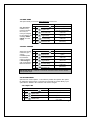
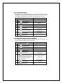
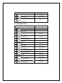
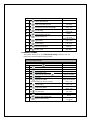
This manual contains programming instructions for the GVC2 Controller
used on the vending machines listed below. Please refer to your service
manual for other information.
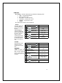
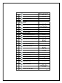
VENDOR
MODEL
HR23
HR32
HR40
RRF-G2 3W
RRF-G2 4W
RRF-G2 5W
SC100
3526, 3526A
3510, 3510A
3509, 3509A
3523, 3523A
3524, 3524A
3525, 3525A
3515, 3515A
3516, 3516A
3534, 3534A
3532
3517, 3517A
3518, 3518A
3541, 3541A
3566, 3566A
3519, 3519A
3565, 3565A
3547, 3547A
3545, 3545A
3520, 3520A
3568, 3568A
3521, 3521A
3567, 3567A
COMBO II
3W COMBI
DZF5000
SZF5000
DZF3000
SZF3000
WS7000
WS5000
WS4000
WS3000
ELEVATOR
P/N 4215507 Rev. D
3536, 3536A
3535, 3535A
3575, 3575A
3538, 3538A
3574, 3574A
3537, 3537A
3573, 3573A
3561, 3561A
3563, 3563A
3557
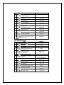
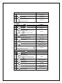
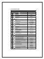
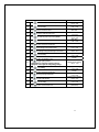
TABLE OF CONTENTS
SERVICE MODE ..................... 1 7.3 FREE VEND RATE ............................... 40 7.4 EXACT CHANGE .................................. 40 1 TUBE FILL/DISPENSE COINS ... 2 7.5 UNCONDITIONAL ACCEPTANCE ...... 41 7.6 MAX CHANGE ...................................... 41 7.7 PROGRAMMABLE POS MESSAGE ... 42 7.8 SHUTDOWN ......................................... 45 7.9 ENERGY SAVINGS .............................. 49 7.0 MOTOR PAIRING ................................. 51 7.4.2 EXACT CHANGE - ALTERNATE RULE. 41 SERVICE MODE BUTTON ...........................1 KEYPAD ........................................................2 DISPLAY ........................................................2 2 MOTOR COUNT .........................3 3 OPTIONS ...................................3 3.1 FORCE VEND..........................................3 3.2 BILL ESCROW ........................................5 3.3 MULTI VEND ...........................................5 3.4 FREE VEND.............................................6 3.6 OPTICAL VEND ......................................6 3.7 POINT OF SALE MESSAGE (pos) ........9 3.8 SETPOINT ...............................................9 3.9 KEYPAD BACKLIGHT ..........................10 4 CONFIGURATION....................10 4.3 ALL ........................................................11 4.4 LANGUAGE...........................................12 4.5 AUTO-REINSTATE ...............................12 4.6 SPACE TO SALES (STS) .....................14 4.7 CUSTOM STS........................................14 4.8 TIME/DATE ............................................15 4.9 HEALTH SAFETY (HS) .........................16 4.0 ADVANCED CONFIGURATION ...........19 4.0.1 BEEP ENABLE ....................................... 19 4.0.2 OPTICS DISABLES ................................ 19 4.0.3 MOTOR TYPE......................................... 19 4.0.4 TALKER.................................................. 20 4.0.5 PASSWORD ........................................... 20 4.0.6 SET DEFAULTS ..................................... 21 4.0.7 TEMP ...................................................... 21 4.0.8 SELECTION STYLE ............................... 23 4.0.9 OPEN DOOR MOTOR HOMING............. 23 4.0.0.1 ELEVATOR ENABLE......................24 4.0.0.2 AUTOMATIED DELIVERY BOX
ENABLE.......................................................24 4.0.0.3 TOUCH COMM ................................25 4.0.0.4 AUTO SERVICE ..............................25 5 PRICING ..................................26 5.3 ALL ........................................................26 5.2 ROW.......................................................26 5.1 ITEM .......................................................27 5.4 COUPON ...............................................27 5.5 TOKEN ...................................................30 5.7 COMBO .................................................32 6 ACCOUNTING .........................33 6.3 ACCOUNTING “ALL” ...........................33 6.2 ACCOUNTING BY ROW .......................33 6.1 ACCOUNTING BY ITEM .......................34 7 ADVANCED OPTIONS .............35 7.1 DISCOUNT ............................................35 7.2 PROMO VEND.......................................39 P/N 4215507 Rev. D
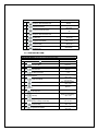
8 TEST MOTOR ......................... 51 9 TEST ALL MOTORS ................ 51 0 DIAGNOSTICS MENU ............. 52 0.1 SYSTEM DIAGNOSTIC ........................ 52 0.2 TEST RELAY ........................................ 52 0.3 LOG ....................................................... 53 0.5 BILL REJECT RATE............................. 53 0.6 IVEND ALIGNED .................................. 53 0.7 ADVANED DIAGNOSTICS................... 54 0.7.1 REFRIG LOG .......................................... 54 0.7.2 DAQ LOG................................................ 54 0.7.3 STS LOG ............................................ 54 0.7.4 HEALTH SAFETY TEST ......................... 55 0.7.5 CAN/BOTTLE DROP SENSOR BIAS..... 56 0.8 DOOR ALERT ....................................... 56 0.9 MANUAL DEFROST ............................. 57 0.0 ELEVATOR ........................................... 57 0.0.1.1 ELEVATOR BOARD SOFTWARE
REVISION ........................................................ 57 0.0.1.2 NUMBER OF TRAYS ........................... 58 0.0.1.3 BAFFLE OPEN/CLOSED .................... 58 0.0.2 AUTO-DOOR MOTOR ....................... 59 0.0.3 DELIVERY LIFT TEST....................... 59 0.0.6 LIFT OPTICS ALIGN ......................... 60 CUSTOMER LEAD THROUGH
MESSAGES.......................... 60 ERROR CODE MESSAGES... 63 ELEVATOR TROUBLE
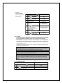
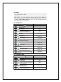
SHOOTING .......................... 71 QUICK REFERENCE GUIDE 81 Record the Model Number and Serial Number of your machine
below. The Model and Serial numbers are needed to obtain quick
service and parts information for your machine. The numbers are
available on the identification plate located on the backside of the
cabinet of the machine.
MODEL NUMBER: ________ SERIAL NUMBER: ___________
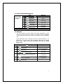
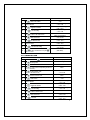
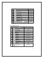
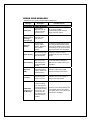
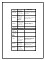
Revision History:
Rev
Date
Reason
A
7/28/05
Initial Document Testing of GVC1 CB500
B
9/05/06
Corrections /Clarifications
C
10/10/10
Corrections/Clarifications
D
08/13/12
Additions/Corrections/Clarifications
0
SERVICE MODE
Use Service Mode to program and service the machine. Use the keypad as an
input device. Watch the display for information while in Service Mode.
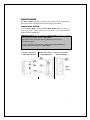
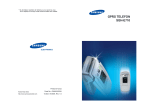
SERVICE MODE BUTTON
To enter Service Mode, press the Service Mode Button located on the top or
upper right corner of the controller cover. See Figure 1. To exit Service Mode,
press the Service Mode Button.
IMPORTANT NOTE: If credit exists when Service Mode is entered, it will be
restored when the machine returns to Sales Mode.
If the display shows a message other than “Motors XX” then see the
troubleshooting guide.
If no key is pressed for approximately 1 minute while in Service Mode, the
controller will automatically return to Sales Mode.
Figure 1. Controller –
Inside Door Mounted
Figure 2. Controller – Figure 2.A Controller—
Cabinet Mounted
Cabinet Mounted
1
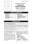
KEYPAD
To program the vendor, use the buttons on the keypad as directed in the step-bystep instructions below.
DISPLAY
Check the display after pressing the Service
Mode Button and/or Keypad Buttons to
make sure that the program is responding
correctly.
Buttons 0-9 are used to move between the
various modes, menus and sub-menus; while
the button is used to save a setting and the
button is used to exit menu without change
or move to higher level menu (See Figure 3).
Figure 3. Keypad
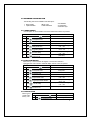
1 TUBE FILL/DISPENSE COINS
TUBE FILL
Tube Fill counts
coins as they are
deposited and
shows the dollar
amount.
STEP
1.
Press Service Mode Button
2.
Press
and deposit coins
Press
two times to exit
3.
DISPLAY
Motor Count or Error
Code **
At least 15 of each
denomination
0.00
TUBE DISPENSE
Tube Dispense
Pays out coins
from the coin
mech. coin
tubes.
This mode also
displays the
current quantity
of coins in the
coin mech. coin
tubes.
STEP
DISPLAY
Motor Count or Error
Code **
1.
Press Service Mode Button
2.
Press
to dispense highest value coin
Value of Coin
3.
Press
to dispense 2nd highest coin
Value of Coin
4.
Press
to dispense 3rd highest coin
Value of Coin
5.
Press
to dispense 4th highest coin
Value of Coin
6.
Press
two times to exit
0.00
IMPORTANT NOTE: For dispensing more than a four denomination coin mech. use keys greater in the
same sequence as shown above.
2
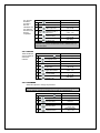
2 MOTOR COUNT
Displays the total
count of working
1.
motors.
2.
3.
STEP
Press Service Mode Button
Press
and wait
Press
to exit
DISPLAY
Motors (--)
Motors ( - - )
(Sales Mode)
NOTE: Motor count includes tray motors, changer escrow motor, elevator motors,
delivery lift and auto door motors briefly (example – shows 40 then goes back to
36d) to show the additional motors and then returns to show only tray count.
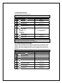
3 OPTIONS
This menu allows access to the following features:
Optics
Point Of Sale Message
Temperature
Keypad Backlight
Drop Sensor Sensitivity
Force Vend
Bill Escrow
Multi Vend
Free Vend
Fast Change
3.1 FORCE VEND
This option forces
the customer to
complete a
purchase once
they have
deposited money
of any form.
STEP
1.
Press Service Mode Button
2.
Press
for Options menu
3.
Press
for Force Vend menu
4.
Press
to toggle ON/OFF
5.
Press
to save the setting
Press
three times to exit
6.
DISPLAY
Motors (--)
Options
Force Vend (Current Setting)
*-exit 1-edit
Force Vend (Choice Flashing)
*-exit #-save
Force Vend (New Setting)
*-exit 1-edit
(Sales Mode)
IMPORTANT NOTE: If a vend is attempted on a configured selection and the
motor fails during this vend, the customer will be allowed to escrow the credit,
regardless of the force vend status.
3
3.2 BILL ESCROW
This option allows
the last bill
accepted to be
returned, provided
the bill acceptor is
capable of such a
feature.
STEP
1.
Press Service Mode Button
2.
Press
for Options menu
3.
Press
for Bill Escrow menu
4.
Press
to toggle ON/OFF
5.
Press
to save the setting
Press
three times to exit
6.
DISPLAY
Motors (--)
Options
Bill Escrow (Current Setting)
*-exit 2-edit
Bill Escrow (Choice Flashing)
*-exit #-save
Bill Escrow (New Setting)
*-exit 2-edit
(Sales Mode)
3.3 MULTI VEND
This option allows the customer to purchase more than one product if enough credit
has been deposited.
STEP
When this option is
active, any credit
remaining after a
vend attempt is not
automatically
returned. At this
point, the customer
has the option of:
1.
Press Service Mode Button
2.
Press
3.
Press
for Multi Vend menu
4.
Press
to toggle ON/OFF
5.
Press
to save the setting
Press
three times to exit
6.
for Options menu
DISPLAY
Motors (--)
Options
Multi Vend (Current Setting)
*-exit 3-edit
Multi Vend (Choice Flashing)
*-exit #-save
Multi Vend (New Setting)
*-exit 3-edit
(Sales Mode)
Making another selection if there's enough credit.
Depositing more money (cash credit from a changer or bill acceptor); or
Pressing coin return to receive remaining credit.
IMPORTANT NOTE: After 5 minutes any credit left on the display will disappear.
For card reader sessions, the Multi Vend feature will function only if the card
reader supports multiple vend capability.
5
3.4 FREE VEND
This option allows you to set the whole machine to Free Vend.
STEP
With Free Vend
enabled, every
product is vended
at no cost, no
money is accepted
by the machine, the
message "FREE
ON US" is on the
display.
1.
Press Service Mode Button
2.
Press
Options
for Options menu
3.
Press
for Free Vend menu
4.
Press
to toggle ON/OFF
5.
Press
to save the setting
Press
three times to exit
6.
DISPLAY
Motors (--)
Free Vend (Current Setting)
*-exit 4-edit
Free Vend (Choice Flashing)
*-exit #-save
Free Vend (New Setting)
*-exit 4-edit
(Sales Mode)
3.5 FAST CHANGE
STEP
Allows the vending
machine to give
change
immediately after
the customers
makes a selection.
If Fast Change is
ON, it overrides the
Multi Vend feature.
1.
Press Service Mode Button
2.
Press
for Options menu
3.
Press
for Fast Change menu
4.
Press
to toggle ON/OFF
5.
Press
to save the setting
Press
three times to exit
6.
DISPLAY
Motors (--)
Options
Fast Change (Current Setting)
*-exit 5-edit
Fast Change (Choice Flashing)
*-exit #-save
Fast Change (New Setting)
*-exit 5-edit
(Sales Mode)
IMPORTANT NOTE: If “OPTICS” is turned ON, the amount of the product displays
until a product drops.
3.6 OPTICAL VEND
Optical Sensor Control Options - This submenu provides the operator with options
for designating product items or rows that are monitored for product delivery by an
optical sensor. Default is ALL selections “ON” unless changed.
3.6.3 Optics All
STEP
1.
Press Service Mode Button
2.
Press
for Options menu
3.
Press
for Optical Vend menu
4.
Press
for All items menu
DISPLAY
Motors (--)
Options
Optical Vend
All Items (Current Setting)
*- exit 3-edit
6
OPTICS ALL CONTINUED
5.
Press
to toggle ON/OFF
6.
Press
to save the setting
Press
four times to exit
7.
DISPLAY
All Items (Choice Flashing)
*-exit #-save
All Items (New Setting)
*- exit 3-edit
(Sales Mode)
3.6.2 Optics by Row
STEP
1.
Press Service Mode Button
2.
Press
for Options menu
3.
Press
for Optical Vend menu
4.
Press
5.
6.
7.
8
9.
DISPLAY
Motors (--)
Options
Optical Vend
Row:- *- exit
Row: XX (Current Setting)
Enter the Row Number
*-exit 1-edit
Row : XX (Choice Flashing)
Press
to toggle ON/OFF
*-exit #-save
Row : XX (New Setting)
Press
to save the setting
*-exit 1-edit
Repeat Steps 4 thru 7 until all desired rows are completed
to enter a row number
Press
to enter another Row or four
times to exit
(Sales Mode)
3.6.1 Optics by Item
STEP
1.
Press Service Mode Button
2.
Press
for Options menu
3.
Press
for Optical Vend menu
4.
Press
to enter the Item
Press
to exit
to enter another item or four times
5.
6.
7.
8.
9.
DISPLAY
Motors (--)
Options
Optical Vend
Item: - - *- exit
Item: XXX (Current Setting)
Enter Item Number
*- exit 1- edit
Item: XXX (Choice Flashing)
Press
to toggle ON/OFF
*- exit #- save
Item: XXX (New Setting)
Press
to save the setting
*- exit 1- edit
Repeat Steps 4 thru 7 until all desired selections are completed
(Sales Mode)
7
3.6 OPTICAL VEND (continued)
The controller must be in Sales Mode. If the accumulated credit is equal to or
larger than the selection price when a selection is entered, the motor
corresponding to that selection is turned on. Selections that are designated as
Optical have an associated vend operation that differs from the normal vend
operation.
For 5 milliseconds at the start of a vend, the iVend™ optical sensor is checked
for blockage.
If blocked - the normal home-switch-vend cycle is used and the optical
sensors are ignored. Both the vend motor and a 10-second vend timeout timer
are started.
The selection motor rotates to the home-switch position.
If there is a home-switch signal, the vend is considered successful.
If after 10 seconds there is no home-switch signal, the vend failed. The
vend motor is shut down and MAKE ANOTHER SELECTION is displayed.
The customer can then press selection buttons to activate this or another
motor, or press the Coin Return.
IMPORTANT NOTE: Force Vend is overridden under this vend cycle.
If not blocked - the iVend™ Sensor System is used. The vend motor and a
10 second vend timeout timer are started.
The selection motor rotates to the home-switch position.
If a product is detected during this time period, the vend is considered
successful.
If after reaching the home-switch position, a product has not been
detected, the vend motor will pause for 1 second while the controller
continues to monitor the optical sensor for product delivery.
If a product is detected during this pause, the vend is considered
successful.
If a product is not detected, the controller initiates a second vend cycle
and a 9-second timer while continuing to monitor the optical sensor.
o If a product is detected during this second cycle, the motor is stopped
immediately. The vend is considered successful. The 2nd Vend Count
is increased by one.
o If a product is not detected before the motor reaches the home-switch
position, or if a 9-second timer runs out, the vend has failed or the
selection is sold out. Such a state will trigger the display message,
MAKE ANOTHER SELECTION , and the amount of credit is displayed.
The customer can press selection buttons to activate this or another
motor or press the Coin Return.
8
3.7 POINT OF SALE MESSAGE (POS)
Turn OFF (or
ON) the default
scrolling display
message.
1.
2.
3.
4.
5.
6.
STEP
DISPLAY
Press Service Mode Button
Motors (--)
Press
for Options menu
Press
for POS menu
Press
to toggle ON/OFF
Press
to save the setting
Press
three times to exit
Options
POS Message (Current Setting)
*- exit 7- edit
POS Message (Choice Flashing)
*- exit # - save
POS Message (New Setting)
*- exit 7- edit
(Sales Mode)
IMPORTANT NOTE: this does not affect the programmed POS message.
3.8 SETPOINT
This menu displays the factory default SET POINT temperature for each
machine type. See section 4.0.7 TEMP for the specific machine refrigeration
modes. Ambient snack machines without a refrigeration system will display
36F.
These temperatures may be adjusted, however it is not recommended. The
temperatures have been set according to NAMA specifications for optimal
product safety. Before making any adjustment sees Temp and Health
Safety section.
STEP
1.
Press Service Mode Button
2.
Press
for Options menu
3.
Press
for Setpoint menu
4.
Press
to edit the Temperature Setpoint
5.
Continue pressing
reached
6.
Press
to save to save the setting
Press
three times to exit
7.
until the desired temperature is
DISPLAY
Motors (--)
Options
Setpoint (Current Setting)F
*- exit 8- edit
Setpoint (Temp flashing)F
*- exit #- save
Setpoint (New Temp)F
*- exit 8- edit
Setpoint (New Temp)F
*- exit 8- edit
(Sales Mode)
9
3.9 KEYPAD BACKLIGHT
This menu controls
the brightness
level of the keypad
backlight
(Default is 3).
STEP
DISPLAY
1.
Press Service Mode Button
Motors (--)
2.
Press
for Options menu
Options
3.
Press
for Backlight menu
KB Backlight (Current Setting)
*- exit 9- edit
4.
Continue pressing
until the
desired setting is reached
Note: 0=Off, 1=Low, 2=Med,
3=High, 4=Max
5.
Press
to save the setting
Press
three times to exit
6.
KB Backlight (Choice Flashing)
*- exit # - save
KB Backlight (New Setting)
*- exit 9- edit
(Sales Mode)
3.0 DROP SENSOR SENSITIVITY
FOR CLOSED FRONT CAN/BOTTLE MACHINE SELECTIONS ONLY.
This menu allows
you to adjust the
Drop Sensor
sensitivity.
1 is most sensitive;
9 is the least
sensitive.
Default is 3.
When Can/Bottle
Mode is ON, the
Drop Sensor is
enabled for vending
bottles or cans.
STEP
DISPLAY
1.
Press Service Mode Button
Motors (--)
2.
Press
for Options menu
Options
3.
Press
menu
for Drop Sensor
Drop Sensor (Current Setting)
*- exit 0- edit
4.
Continue pressing
until the
desired setting is reached 1-9
5.
Press
to save the setting
Press
three times to exit
6.
Drop Sensor (Choice Flashing)
*- exit # - save
Drop Sensor (New Setting)
*- exit 0- edit
(Sales Mode)
NOTE: The Drop Sensor setting will count up to 9 and then start over at 1.
4 CONFIGURATION
This menu allows access to the following features.
Date/Time
Item
Health Safety
Row
Advanced Configuration
All
Selection Style
Language
Elevator
Auto-Reinstate
Delivery Lift
Space to Sales (STS)
Custom STS
This menu provides access to sub-menus that set Can, Bottle or Snack type of
product to each item, entire row or entire machine.
10
4.3 ALL
To set ENTIRE
MACHINE to
Snack, Can, or
Bottle
STEP
1.
Press Service Mode Button
2.
Press
for Configuration menu
3.
Press
4.
Press
to toggle between Snack,
Can, Bottle
5.
Press
to save the setting
Press
four times to exit
6.
for All Items menu
DISPLAY
Motors (--)
Configuration
All Items: (Current Setting)
*- exit 1- edit
All Items: (Choice Flashing)
*- exit #- save
All Items: (New Setting)
*- exit 1- edit
(Sales Mode)
4.2 ROW
Provides the option
of designating rows
that contain cans,
bottles or snack.
STEP
1.
Press Service Mode Button
2.
Press
for Configuration menu
3.
Press
to enter a row
4.
Enter Row number
5.
Press
to toggle between Can,
Bottle and Snack
6.
7.
Press
to save the setting
Press
three times to exit
DISPLAY
Motors (--)
Configuration
Row: - *- exit
Row: XX (Current Setting)
*- exit 1- edit
Row: XX (Choice Flashing)
*- exit # - save
Choice stops flashing and display
returns to:
Row: - *- exit
(Sales Mode)
IMPORTANT NOTE: For selections designated as either cans or bottles, the vend motor
runs continuously during the vend cycle until a drop sensor signals the controller, or the
maximum vend time of 9 seconds concludes.
4.1 ITEM
Before setting this
option, a row or the
entire machine must
be set to Can/bottle.
Each item in that
row or entire
machine may be set
to CAN or BOTTLE.
When Can/Bottle
Mode is ON, the
STEP
1.
Press Service Mode Button
2.
Press
for Configuration menu
3.
Press
to enter an item
4.
5.
Enter selection number
Press
to toggle Can/Bottle
DISPLAY
Motors (--)
Configuration
Item: - - *- exit
Item: XXX (Current Setting)
*- exit 1- edit
Item: XXX (Choice Flashing)
*-exit # - save
11
Drop Sensor is
enabled for vending
bottles or cans.
CONFIG BY ITEM CONTINUED
DISPLAY
Choice stops flashing and display
returns to:
Press
to save the setting
Item: - - *- exit
Repeat Steps 4 thru 6 until all selections are completed
6.
7.
8.
Press
4.4 LANGUAGE
Language Message
This menu function allows
the operator to choose a
specific language in
which sales mode
messages are displayed.
The following languages
are available:
English
Spanish
French
Italian
German
Danish
Dutch
Turkish
Auxiliary
3 times to exit
(Sales Mode)
STEP
DISPLAY
1.
Press Service Mode Button
2.
Press
for Configuration menu
Motors (--)
Configuration
3.
Press
for Language menu
4.
Press
to toggle between the
languages
5.
Press
6.
Press Service Mode Button
to save the setting
Language (Current Setting)
*- exit 4- edit
Language: (Choice Flashing)
*- exit # - save
Language (New Setting)
*- exit 4- edit
(Sales Mode)
IMPORTANT NOTE: If auxiliary is selected, an alternative list of operator created sales
mode messages is used (see Section 7.3).
4.5 AUTO-REINSTATE
CAUTION: Auto-Reinstate affects both the host machine and all attached
satellite units.
Auto-Reinstatement of Failed Selections - This feature is for a satellite soft
drink or similar vendor utilizing a Sold Out or Empty switch. Normally, when
an empty selection is detected during an attempted vend, that selection is
recorded as inoperative and requires resetting before it can be vended again.
Satellite units utilize a range of selections within the controller. Programming
this range of selections into Auto-Reinstatement eliminates the necessity of
manually resetting the controller after re-loading a selection that is in a Sold
Out condition.
IMPORTANT NOTE: If iVend™ Optical System is installed, then all selections are set to
auto-reinstate “on” unless changed.
4.5.3 AUTO-REINSTATE WHOLE MACHINE
STEP
1.
Press Service Mode Button
2.
Press
for Configuration menu
DISPLAY
Motors (--)
Configuration
12
AUTO-REINSTATE MACH CONTINUED
3.
Press
for Auto-Reinstate menu
4.
Press
for All Items menu
5.
Press
to toggle ON/OFF
6.
Press
to save the setting
Press
four times to exit
7.
DISPLAY
Auto-Reinstate
All Items (Current Setting)
*- exit 3- edit
All Items (Choice Flashing)
*-exit # - save
All Items (New Setting)
*- exit 3- edit
(Sales Mode)
4.5.2 AUTO-REINSTATE BY ROW
STEP
1.
Press Service Mode Button
DISPLAY
Motors (--)
2.
Press
for Configuration menu
Configuration
3.
Press
for Auto-Reinstate menu
Auto-Reinstate
4.
Press
to enter a row
5.
Enter Row Number
6.
Press
to toggle the Row ON/OFF
7.
Press
to save the setting
Press
to enter another row or four times to exit
8.
Row: - *- exit
Row: XX (Current Setting)
*- exit 1- edit
Row: XX (Choice Flashing)
*- exit # - save
Row: XX (New Setting)
*- exit 1- edit
(Sales Mode)
4.5.1 AUTO-REINSTATE BY ITEM
STEP
1.
Press Service Mode Button
DISPLAY
Motors (--)
2.
Press
for Configuration menu
Configuration
3.
Press
for Auto-Reinstate menu
Auto-Reinstate
4.
Press
to enter an item
5.
Enter Item Number
6.
Press
to toggle Item ON/OFF
7.
Press
to save the setting
Press
to enter another item or five times to exit
8.
Item: - - *- exit
Item: XXX (Current Setting)
*- exit 1- edit
Item: XXX (Choice Flashing)
*- exit # - save
Item: XXX (New Setting)
*- exit 1- edit
(Sales Mode)
13
4.6 SPACE TO SALES (STS)
STEP
The following
settings are
available:
STS Off
Whole Rows
Half Rows
By 2’s
Whole Machine
Custom
MZF/SZF
Custom
DISPLAY
Motors (--)
1.
Press Service Mode Button
2.
Press
for Configuration menu
3.
Press
for STS menu
4.
Press
to toggle through options
5.
Press
to save the setting
Press
three times to exit
6.
Configuration
StS (Current Setting)
*- exit 6- edit
StS (Choice Flashing)
*- exit # - save
StS (New Setting)
*- exit 6- edit
(Sales Mode)
IMPORTANT NOTE: If custom is chosen, see section 4.7 for instructions.
4.7 CUSTOM STS
IMPORTANT NOTE: Before setting this option, you must select “Custom” as your
setting under menu 4.6.
This option is used to tie selections together that do not fall under any of the
categories under menu 4.6 (Example: 10; 20; 24).
STEP
1.
Press Service Mode Button
2.
Press
for Configuration menu
3.
Press
for STS menu
4.
Press
to toggle to Custom
5.
Press
to save the setting
Press
to return to Configuration menu
7.
Press
to STS selection
8.
Enter first selection number
9.
Press
to clear links menu
10.
Press
to clear current links settings
11.
Press
to add new Selection
12.
Enter Next Selection
13.
Press
to add another selection
(to enter more selections repeat steps 11
and 12)
6.
14.
Press
six times to exit
DISPLAY
Motors (--)
Configuration
STS (Current Setting)
*- exit 6- edit
STS Custom
*- exit # - save
STS Custom
*- exit 6- edit
Configuration
STS - - -:
*- exit
STS XXX: (Current Selection)
*- exit # - Add 1-Clear
XXX: Clear links?
*- exit # - clear?
XXX: Cleared
*- exit # - Add 1- Clear
XXX: - - *- exit
XXX: YYY
*- exit # - Add
XXX: - - - YYY, ZZZ
(The screen displays the selections you have
entered. After 3 selections the screen will scroll
the selections).
(Service Mode)
14
4.8 TIME/DATE
Sets the time and date for timed operations.
The following submenus are available:
Date
Time
Daylight Savings
4.8.1 DATE
STEP
DISPLAY
1.
Press Service Mode Button
2.
Press
for Configuration menu
3.
Press
for Date/Time menu
4.
Press
for Date menu
5.
Press
6.
Enter the Date
7.
Press
to save the Date
Press
four times to exit
8.
Motors (--)
Configuration
Date/Time
(Current Date)
*- exit # - edit
MM/DD/YYYY
*- del # - save
MM/DD/YYYY
*- del # - save
(New Date)
*- exit # - edit
to edit the date
(Sales Mode)
4.8.2 TIME
Time Setting - This
menu controls and
displays the current time
of day. The display will
show a 24-hour format.
Examples:
08:05 a.m. = TIME 08.05
01:15 p.m. = TIME 13.15
11:45 p.m. = TIME 23.45
TIME SETTING
STEP
1.
Press Service Mode Button
2.
Press
for Configuration menu
3.
Press
for Date/Time menu
4.
Press
for Time menu
5.
Press
6.
Enter the Time
6.
Press
to save the Time
Press
four times to exit
7.
to edit the Time
DISPLAY
Motors (--)
Configuration
Date/Time
(Current Time)
*- exit # - edit
09:00:25
*- del # - save
09:00:25
*- del # - save
(New Time)
*- exit # - edit
(Sales Mode)
15
4.8.3 DAYLIGHT SAVINGS
This menu controls and displays the currently active daylight savings rule.
STEP
1.
Press Service Mode Button
2.
Press
for Configuration menu
3.
Press
for Date/Time menu
4.
Press
5.
Press
to toggle between settings
(North America, OFF, Australia, Europe)
6.
Press
to save the setting
Press
four times to exit
7.
for DST menu
DISPLAY
Motors (--)
Configuration
Date/Time
DST (Current Setting)
*- exit 3 - edit
DST (Choice Flashing)
8- edit # - save
DST (New Setting)
*- exit 3- edit
(Sales Mode)
4.9 HEALTH SAFETY (HS)
THE HEALTH SAFETY FEATURE CAN NOW BE CONFIGURED FOR 2
TEMPERATURE ZONES. A LOWER ZONE AND AN UPPER ZONE AS
DETAILED IN THE HEALTH SAFETY MENUS BELOW.
The HEALTH SAFETY feature prevents the sale of perishable food if the air
temperature inside the Food Vendor compartment rises above the Health Safety
temperature limit for more than 15 minutes. The perishable products being vended
must match the refrigeration configuration.
Warning: These settings require specific refrigeration systems and options in a
machine. Please review this document and consult the machine service manual
and if necessary, Vendnet Service at 1-800-833-4411 before making any
changes to the machine settings. Please have machine model number and
serial number information when calling Vendnet Service,
HEALTH SAFETY MENUS - This menu allows the user to specify the operating
zone to meet health safety requirements for cold and frozen food. The health safety
requirements can also be applied to an individual Item(s), Row(s), or ALL (whole
machine). If the health safety requirements are violated then the Item(s), Row(s) or
the whole machine is shut down accordingly.
HEALTH SAFETY ZONES - Health Safety settings are split into two zones, Upper
Zone and Lower Zone. Only the Lower Zone setting will be used when the
machine is configured as a Cold, Cold Food, Single Zone (SZ), Dual Zone
(DZ),Single Zone Frozen (SZF) or Single Zone Cold Food (SCF). The Upper
Zone setting is used is for the Multi-Zone Frozen (MZF) temperature mode. On a
machine using the MZF setting, the Upper Zone follows the HS rules for Cold Food
and the Lower Zone follows the HS rules for Frozen Food.
16
IMPORTANT! The operator is responsible for ensuring the health
safety of vended products and to verify the machine HS settings.
Make sure to Enable All Items and Enable HS Zone Lower and/or
Upper Zone before making any other changes.
4.9.3 HS ALL ITEMS
STEP
DISPLAY
1.
Press Service Mode Button
2.
Press
for Configuration menu
Configuration
3.
Press
for Health Safety menu
Health Safety
Press
to edit the Lower Zone or
Press
to edit the Upper Zone
5.
Press
for All Items
6.
Press
to toggle ON/OFF
7.
Press
to save the setting
Press
to exit All Items
4
8.
9.
Press
to edit HS Zone ON/OFF
10.
Press
to toggle HS Zone ON/OFF
11.
Press
to save the setting
12.
13.
14..
Motors (--)
Lower Zone or Upper Zone
All Items (Current Setting)
*- exit 3- edit
All Items (Choice Flashing)
*- exit # - save
All Items (New Setting)
*- exit 3- edit
Lower Zone or Upper Zone
Enable (Current Setting)
*- exit 9- edit
Enable (Choice Flashing)
*- exit # - save
Enable (New Setting)
*- exit 9- edit
Press
to exit back to main HS menu
Repeat steps 4 thru 12 for another Zone or go to step 14.
Press
five times to exit
Health Safety
(Sales Mode)
4.9.2 HS BY ROW
STEP
1.
Press Service Mode Button
DISPLAY
Motors (--)
2.
Press
for Configuration menu
Configuration
3.
Press
for Health Safety menu
Health Safety
Press
to edit the Lower Zone or
Press
to edit the Upper Zone
5.
Press
to enter a row number
6.
Enter Row Number
7.
Press
4.
to toggle row ON/OFF
Lower Zone or Upper Zone
Row: - *- exit
Row: XX (Current Setting)
*- exit 1- edit
Row: XX (Choice Flashing)
*- exit # - save
17
HS BY ROW CONTINUED
8.
9.
Press
to save row ON/OFF
Press
to exit and enter another row or
press
two times to go back to the Zone
Choice screen
DISPLAY
Row: XX (New Setting)
*- exit 1- edit
Lower Zone or Upper Zone
Enable (Current Setting)
*- exit 9- edit
Enable (Choice Flashing)
Press
to toggle HS Zone ON/OFF
*- exit # - save
Enable (New Setting)
Press
to save the setting
*- exit 9- edit
Repeat steps 4 thru 12 for another Zone or go to step 14
10.
11.
12.
13.
14.
Press
to edit HS Zone ON/OFF
Press
four times to exit
(Sales Mode)
4.9.1 HS BY ITEM
STEP
DISPLAY
1.
Press Service Mode Button
2.
Press
for Configuration menu
Configuration
3.
Press
for Health Safety menu
Health Safety
Press
to edit the Lower Zone or
Press
to edit the Upper Zone
5.
Press
to enter an item
6.
Enter Item Number
7.
Press
to toggle Item ON/OFF
8.
Press
to save Item setting
Press
to enter another item or
Press
screen
two times for the Zone Choice
4.
9.
10.
11.
12.
13.
13.
Motors (--)
Lower Zone or Upper Zone
Item: - - *- exit
Item: XXX (Current Setting)
*- exit 1- edit
Item: XXX (Choice Flashing)
*- exit # - save
Item: XXX (New Setting)
*- exit 1- edit
Lower Zone or Upper Zone
Enable (Current Setting)
*- exit 9- edit
Enable (Choice Flashing)
Press
to toggle HS ON/OFF
*- exit # - save
Enable (New Setting)
Press
to save the setting
*- exit 9- edit
Repeat Steps 4 thru 12 for another Zone or go to step 14
Press
to edit HS Zone ON/OFF
Press
four times to exit
(Sales Mode)
18
4.0 ADVANCED CONFIGURATION
The following menus are available under this option:
Beep Enable
Optics Disables
Motor Type
Talker Password
Set Defaults
Temperature
Selection Style
4.0.1 BEEP ENABLE
Use this option to choose whether a sound is heard when buttons are pressed.
STEP
1.
Press Service Mode Button
2.
Press
3.
4.
Press
for Password menu
Enter Password (default 2314)
5.
Press
for Beep Enable menu
6.
Press
to toggle Beep ON/OFF
7.
Press
to save the setting
Press
four times to exit
8.
for Configuration menu
DISPLAY
Motors (--)
Configuration
Password
Advanced Config
Beep Enable (Current Setting)
*- exit 1- edit
Beep Enable (Choice Flashing)
*- exit # - save
Beep Enable (New Setting)
*- exit 1- edit
(Sales Mode)
4.0.2 OPTICS DISABLES
When set up — if the I-vend is not aligned, or sensors are blocked or
unplugged, the “Out of Service” POS will display until the I-vend is repaired.
STEP
1.
Press Service Mode Button
2.
Press
3.
4.
Press
for Password menu
Enter Password (default 2314)
5.
Press
for Optics Disables menu
6.
Press
to toggle Optics Disables ON/OFF
7.
Press
to save the setting
Press
four times to exit
8.
for Configuration menu
4.0.3 MOTOR TYPE
Motor Type is
STEP
preset at the
1. Press Service Mode Button
factory. The
2. Press
for Configuration menu
DISPLAY
Motors (--)
Configuration
Password:
Advanced Configuration
Optics Disables (Current Setting)
*- exit 2- edit
Optics Disables: (Choice Flashing)
*- exit # - save
Optics Disables (New Setting)
*- exit 2- edit
(Sales Mode)
DISPLAY
Motors (--)
Configuration
19
only time this
should be
checked is
after the
installation of a
new board to
assure that the
board is
compatible.
MOTOR TYPE CONTINUED
3.
4.
Press
for Password menu
Enter Password (default 2314)
5.
Press
6.
Press
to toggle from 2 wire, 2
wire 1m* or 3 wire motors
7.
Press
to save the setting
Press
four times to exit
8.
for Motor Type menu
DISPLAY
Password:
Advanced Configuration
Motor Type (Current Setting)
*- exit 3- edit
Motor Type (Choice Flashing)
*- exit # - save
Motor Type (New Setting)
*- exit 3- edit
(Sales Mode)
*NOTE: The 2 wire 1M setting is used on select Frozen Food
machines only. Contact Vendnet Service at 1-800-833-4411 for
more information.
4.0.4 TALKER
Talker assists the
vision impaired to
service the
machine.
STEP
1.
Press Service Mode Button
2.
Press
3.
4.
Press
for Password menu
Enter Password (default 2314)
5.
Press
for Talker menu
6.
Press
to toggle Talker ON/OFF
7.
Press
to save the setting
Press
four times to exit
8.
for Configuration menu
DISPLAY
Motors (--)
Configuration
Password
Advanced Configuration
Talker (Current Status)
*- exit 4- edit
Talker (Choice Flashing)
*- exit # - save
Talker (New Status)
*- exit 4- edit
(Sales Mode)
4.0.5 PASSWORD
Allows the operator to change the password
IMPORTANT NOTE: If you forget your personal password after changing it
from the default, contact Technical Service for help at 1-800-833-4411.
STEP
1.
Press Service Mode Button
2.
Press
3.
4.
Press
for Password menu
Enter Password (default 2314)
5.
Press
for Password menu
6.
Press
to edit the Password
for Configuration menu
DISPLAY
Motors (--)
Configuration
Password
Advanced Config
Password (Current)
*- exit # - edit
Password (Flashing)
*- del # - save
20
PASSWORD CONTINUED
DISPLAY
7.
Press
to delete the existing
password, then use the keypad to
enter a new password
Password (New)
*- exit # - save
8.
Press
Password (New)
*- exit # - edit
9.
Press
to save the new Password
four times to exit
(Sales Mode)
4.0.6 SET DEFAULTS
Use these steps to reset the defaults for the following:
IMPORTANT
NOTE: If you
have previously
changed your
password, this
will reset it
back to the
factory default
of 2314
STEP
1.
Press Service Mode Button
2.
Press
3.
4.
Press
for Password menu
Enter Password (default 2314)
5.
Press
for Set Defaults menu
Press
for a standard default or
Press
for a custom* default
7.
Press
for Reset menu
8.
Press
to Reset Options
Press
six times to exit
6.
9.
for Configuration menu
DISPLAY
Motors (--)
Configuration
Password
Advanced Config
Set Defaults
Set Defaults 1 or
Set Defaults 2
‘0’ to reset options
*- exit
Resetting…Done
*- exit
(Sales Mode)
*NOTE: Contact Vendnet Service at 1-800-833-4411 for more information on
the Custom Default option
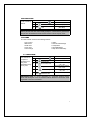
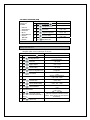
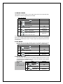
4.0.7 TEMP
This menu
allows the board
to electronically
control the
refrigeration
system for a
specific machine
and refrigeration
type.
STEP
1.
Press Service Mode Button
2.
Press
3.
4.
Press
for Password menu
Enter Password (default 2314)
5.
Press
6.
Press
to toggle between Snack,
Cold, Cold Food, Slackened, Frozen,
Dual Zone, Dual Upper -6, Chilled,
MZF,MZF -2, MZF -5, SZ Frozen, SZ
Frozen -2, SZ Frozen -5, SZ Cold, SZ
Cold -1
for Configuration menu
for Temperature menu
DISPLAY
Motors (--)
Configuration
Password
Advanced Config
Temp (Current Setting)
*- exit 7- edit
Temp (Choice Flashing)
*- exit # - save
21
TEMP CONTINUED
7.
8.
Press
to save the setting
Press
four times to exit
DISPLAY
Temp (New Setting)
*- exit 7- edit
(Sales Mode)
Warning: These settings require specific refrigeration systems and options in a
machine. Please consult the machine service manual and Vendnet Service at
1-800-833-4411 before making any changes to this setting.
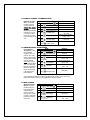
MODE
TEMPERATURE
SET POINT
Snack
Cold
Cold Food
Slackened
Frozen
Dual Zone
with Upper
Zone Heater
N/A
36°F (2.2°C)
38°F (2.2°C)
15°F (-9°C)
-10°F (-23.2°C)
Upper zone
63°F (17.2°C)
Lower zone
36°F (2.2°C)
Upper zone
57°F (13.9°C)
Lower zone
36°F (2.2°C)
61°F (16.7°C)
Upper zone
36°F (2.2°C)
Lower zone
-10°F (-23.2°C)
Upper zone
36°F (2.2°C)
Lower zone
-12°F (-24.4°C)
Upper zone
36°F (2.2°C)
Lower zone
-15°F (-26°C)
-10°F (-23.2°C)
Dual Zone
with Upper
Zone Heater
Chilled
Multi-Zone
Frozen
Multi-Zone
Frozen -12°F
Multi-Zone
Frozen -15°F
Single Zone
Frozen Food
Single Zone
Frozen Food
-12°F
Single Zone
Frozen Food
-15°F
Single Zone
Cold Food
Single Zone
Cold Food
35°F
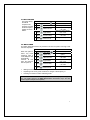
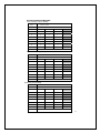
SERVICE
MODE
DISPLAY
Snack
Cold
Cold Food
Slackened
Frozen
Dual Zone
Dual upper
-6
SALES MODE
DISPLAY
HEALTH
SAFETY
N/A
T1= 36F
T1= 38F
T1= 15F T2= 15F
T1= -10F T2=-10F
T3= 63F
Yes
Yes
Yes
Yes
Yes
T1= 36F
Yes
T3= 57F
Yes
T1= 36F
Yes
Chilled
MZF
T1= 61F
T3= 36F
T1= -10F T2= -10F
No
Yes
Yes
MZF-2
T3= 36F
T1= -12F T2= -12F
Yes
Yes
MZF-5
T3= 36F
T1= -15F T2= -15F
Yes
Yes
SZ Frozen
T3= -10F T2= -10F
Yes
-12°F (-24.4°C)
SZ Frozen -2
T3= -12F T2= -12F
Yes
-15°F (-26°C)
SZ Frozen -5
T3= -15F T2= -15F
Yes
36°F (2.2°C)
SZ Cold
T3= 36F
Yes
35°F (1.6°C)
SZ Cold -1
T3= 35F
Yes
22
4.0.8 SELECTION STYLE
This menu programs the selection input.
IMPORTANT NOTE: This is to be set ONLY if a USD satellite is used.
STEP
1.
Press Service Mode Button
2.
Press
3.
Press
for Password menu
Enter Password (default 2314)
4.
5.
Press
Press
6.
7.
8.
for Configuration menu
for Selection Style menu
to toggle between
*or # USD (Default)
Three Digit
Two Digit +40
Two Digit Even
Press
to save the setting
Press
four times to exit
DISPLAY
Motors (--)
Configuration
Password
Advanced Config
Sel style (Current Setting)
*- exit 8- edit
Sel Style (Choice Flashing)
*- exit # - save
Sel Style (New Setting)
*- exit 8- edit
(Sales Mode)
IMPORTANT NOTE: *or # is pushed to select from a USD FROZEN or COLD FOOD
Two Digit Even is used for the USD Combination
Three Digit requires all selections to use a 3-digit input
4.0.9 OPEN DOOR MOTOR HOMING
With the Open Door Motor Homing feature set to ON every time the door of the
machine is opened all motors not at the home position will be moved to the home
position. This feature requires the machine to have a door switch assembly. To
purchase a door switch assembly please contact Vendnet Parts by phone at 1-800833-4411.
CAUTION: When motors are homed, product may be vended from tray location.
STEP
1.
Press Service Mode Button
2.
Press
3.
Press
for Password menu
Enter Password (default 2314)
4.
for Configuration menu
5.
Press
for Homing menu
6.
Press
to toggle between ON/OFF
7.
Press
to save new setting
Press
four times to exit
8.
DISPLAY
Motors (--)
Configuration
Password
Advanced Config
Homing (Current Setting)
*- exit 9- edit
Homing (Choice Flashing)
*- exit # - save
Homing (New Setting)
*- exit 9- edit
(Sales Mode)
23
4.0.0.1 ELEVATOR ENABLE
The function of the elevator machine is to gently vend an item to avoid
breakage. This is done by having the delivery bin move to the shelf that item is
on and back to the position for the customer to remove from the machine.
STEP
DISPLAY
1.
Press Service Mode Button
Motors ( - - )
2.
Press
Configuration
3.
4.
Press
for Password menu
Enter Password (default-2314)
5.
Press
for Configuration menu
for Peripherals menu
6.
Press
for Elevator menu
7.
Press
to toggle the setting ON/OFF
8.
Press
to save the setting
Press
five times to exit
9.
Password:
Advanced Config
Peripherals
Elevator Enable (Current Setting)
*-exit 1-edit
Elevator Enable (Choice Flashing)
*-exit #-save
Elevator Enable (New Setting)
*-exit 1-edit
(Sales Mode)
4.0.0.2 AUTOMATIED DELIVERY BOX ENABLE
The function of the delivery lift is to lift the purchased product higher. This
makes it easier for customer to get their product.
STEP
DISPLAY
1.
Press Service Mode Button
Motors ( - - )
2.
Press
Configuration
3.
4.
Press
for Password menu
Enter Password (default-2314)
5.
Press
for Configuration menu
for Peripherals menu
6.
Press
7.
Press
to toggle the setting. Choices are:
Button – requires customer to push the
blue button to raise the lift after each vend
Auto – lift will raise after each vend
Off – turns the lift off
8.
Press
to save the setting
Press
five times to exit
9.
for Auto Lift menu
Password:
Advanced Config
Peripherals
Auto Lift (Current Setting)
*-exit 2-edit
Auto Lift (Choice Flashing)
*-exit #-save
Auto Lift (New Setting)
*-exit 2-edit
(Sales Mode)
24
4.0.0.3 TOUCH COMM
With this feature turned on the controller will communicate with the optional
touch screen.
STEP
DISPLAY
1.
Press Service Mode Button
Motors ( - - )
2.
Press
Configuration
3.
4.
Press
for Password menu
Enter Password (default-2314)
5.
Press
for Configuration menu
for Peripherals menu
6.
Press
for Touch Comm menu
7.
Press
to toggle the setting ON/OFF
8.
Press
to save the setting
Press
five times to exit
9.
Password:
Advanced Config
Peripherals
Touch Comm (Current Setting)
*-exit 3-edit
Touch Comm (Choice Flashing)
*-exit #-save
Touch Comm (New Setting)
*-exit 3-edit
(Sales Mode)
4.0.0.4 AUTO SERVICE
With this feature turned on the controller will automatically enter the service
modes upon door opening.
NOTE: This feature requires the installation of the optional door switch
assembly. To purchase a door switch assembly please contact Vendnet Parts
by phone at 1-800-833-4411.
STEP
DISPLAY
1.
Press Service Mode Button
Motors ( - - )
2.
Press
Configuration
3.
4.
Press
for Password menu
Enter Password (default-2314)
5.
Press
for Configuration menu
for Peripherals menu
6.
Press
for Auto Service menu
7.
Press
to toggle the setting ON/OFF
8.
Press
to save the setting
Press
five times to exit
9.
Password:
Advanced Config
Peripherals
Auto Service (Current Setting)
*-exit 4-edit
Auto Service (Choice Flashing)
*-exit #-save
Auto Service (New Setting)
*-exit 4-edit
(Sales Mode)
25
5 PRICING
Price Setting - This menu allows three (3) methods for assigning prices:
ITEM — by individual selections
ROW— by shelf or tray
ALL ITEMS — by entire machine.
COUPONS — by Item, Row, or ALL
TOKENS — by Item, Row, or ALL
COMBO
The maximum price that can be set is $655.35.
5.3 ALL
This menu allows you
to set the selection
price of every item all
at once.
Time Saving Tip:
Instead of setting the
price of each item one
at a time, it is much
faster to set the
common price of the
entire machine; then
go back and set the
price of each item or
row.
STEP
DISPLAY
1.
Press Service Mode Button
Motors (--)
2.
Press
for Pricing menu
3.
Press
4.
Enter Price
5.
press
6.
for All Items menu
to save the Price
Press
three times to exit
Pricing
All Items: (Current Price)
*- exit # - save
All Items: (Current Price)
*- del # - save
All Items: (New Price)
*- exit
(Sales Mode)
5.2 ROW
Use this menu to set
the price of a row
(shelf) all at the same
time.
Time Saving
Suggestion:
Instead of setting the
price of one item at a
time, set the common
price of a Row, then go
back and set the price of
each item.
STEP
DISPLAY
1.
Press Service Mode Button
Motors (--)
2.
Press
3.
4.
5
6.
7.
8.
for Pricing menu
Press
to enter a row
Enter row number
Example: Top row=01,
row below top row=02, etc.
Pricing
Row: - - $0.00
*- exit
Row: XX $(New Price)
*- exit # - next
Row: XX $(New Price)
*- exit # - save
Enter Price
Press
to save the new price, Row: XX $(Current Price)
the program will automatically go
*- exit # - next
to the next row
Repeat steps 4 and 5 until all desired rows are completed
Press
four times to exit
(Sales Mode)
26
5.1 ITEM
This menu allows
price setting by each
selection item.
STEP
DISPLAY
1.
Press Service Mode Button
Motors (--)
2.
Press
for the Pricing menu
3.
Press
to enter an item
4.
Enter Item number
5.
Enter Price
6.
Press
to save the new
price. The program will
automatically go to the next
selection number
7.
Repeat steps 4 and 5 until all desired selections are completed
8.
Press
Pricing
Item: --- $0.00
*- exit
Item: XXX $(New Price)
*- exit # - next
Item: XXX $(New Price)
*- exit # - save
four times to exit
Item:XXX $(Current Price)
*- exit # - next
(Sales Mode)
5.4 COUPON
Allows the operator to designate the values of coupons that are accepted
by pre-programmed validators. There are 5 programmable settings.
Value Coupon - This menu enables the use of coupons – this option requires
a programmed validator [MDB version]. Several sub-menus are available that
allow setting of the values of coupons. This feature also allows coupons to be
set by Item, Row, or All.
If space to sales whole machine is “on” and you are setting Coupons by Row
the Row must be set as row1.
IMPORTANT NOTE: Coupon Value Setting - Sets the value of a coupon to
be used with this vendor. Up to five different coupons can be set.
IMPORTANT NOTE: After one coupon is accepted, further coupons will not be
accepted until a successful vend has taken place.
IMPORTANT NOTE: If no value is set, coupons will be shown as free vends.
If using both coupons and tokens there are only five selection combinations
available. Example: If coupon1 is set for “all” items, token1 is also set for all
items.
5.4.3 COUPON “ALL”
STEP
1.
Press Service Mode Button
2.
Press
for Price menu
3.
Press
for Coupons menu
DISPLAY
Motors (--)
Price
Coupons
27
COUPON “ALL” CONTINUED
4.
Press
for Coupon1 (Press corresponding
number 2-5 for additional coupons)
5.
Press
for All items
6.
Press
to toggle ON/OFF
7.
Press
to save the new setting
Press
to Coupon1 menu
8.
9.
Press
10.
Press
11.
Enter Coupon value
12.
Press
to save the value setting
Press
two times to edit coupon 2-5 or press
13.
to enter Coupon Value menu
to edit Coupon1 value
DISPLAY
Coupon1
All Items (Current Setting)
*- exit 3- edit
All Items (Choice Flashing)
*- exit # - save
All Items (New Setting)
*- exit 3- edit
Coupon1
Coupon1: $0.00
*- exit # - edit
Coupon1: $0.00
*- exit # - OK
Coupon1: $0.00
*- del # - save
Coupon1: $(New Value)
*- exit # - edit
(Sales Mode)
four times to exit menu
5.4.2 COUPON BY ROW
STEP
DISPLAY
1.
Press Service Mode Button
2.
Press
for Pricing menu
Pricing
3.
Press
for Coupon menu
Coupons
4.
Press
for Coupon1 (Press corresponding
number 2-5 for additional coupons)
5.
Press
to Verify All Items “OFF”
(If All Items “ON” refer to 5.4.3)
6.
Press
to return to the Coupon1 menu
7.
Press
to enter a row
8.
Enter Row Number
9.
Press
10. Press
11.
Press
12. Press
13. Press
to toggle Row ON/OFF
to save the setting
twice to return to the Coupon1 menu
to enter Coupon Value menu
to edit Coupon1 Value
Motors (--)
Coupon1
All Items: OFF
*- exit 3- edit
Coupon1
Row: - *- exit
Row: XX (Current Setting)
*- exit 1- edit
Row: XX (Choice Flashing)
*- exit # - save
Row: XX (New Setting)
*- exit 1- edit
Coupon1
Coupon1: (Current Value)
*- exit # - edit
Coupon1: (New Value)
*- del # - save
28
COUPON BY ROW CONTINUED
14.
Enter Coupon value
15. Press
16.
Press
to save the value
two times to edit next coupon, or press
DISPLAY
Coupon1: $0.00
*- del # - save
Coupon1: (New Value)
*- exit # - edit
(Sales Mode)
five times to exit menu
5.4.1 COUPON BY ITEM
STEP
DISPLAY
1.
Press Service Mode Button
2.
Press
for Pricing menu
Pricing
3.
Press
for Coupon menu
Coupon
4.
Press
for Coupon1 (Press corresponding number
2-5 for additional coupons)
5.
Press
to Verify All Items “OFF”
(If All Items “ON” refer to 5.4.3)
6.
Press
to return to the Coupon1 menu
7.
Press
8.
Enter Item Number
9.
Press
10. Press
11.
Press
to enter an item
to toggle ON/OFF
to save the setting
twice to return to the Coupon1 menu
12. Press
to enter Coupon Value menu
13. Press
to edit value
11. Enter Coupon value
14. Press
to save the value setting
two times to edit Coupon 2-5 or press
15. Press
five times to exit to sales mode
Motors ( - - )
Coupon1
All Items: OFF
*- exit 3- edit
Coupon1
Item: - - - *-exit
Item: XXX (Current Setting)
*- exit 1- edit
Item: XXX (Choice Flashing)
*- exit # - save
Item: XXX (New Setting)
*- exit 1- edit
Coupon1
Coupon1: (Current Value)
*- exit # - edit
Coupon1: $0.00
*- del # - save
Coupon1: $0.00
*- del # - save
Coupon1: (New Value)
*- exit # - edit
(Sales Mode)
29
5.5 TOKEN
This option allows the operator to designate the values of tokens accepted by
pre-programmed coin mechs.
Value Token- This menu enables the use of tokens; this option requires an
MDB version coin mechanism/changer. Several sub-menus are available that
allow setting token values. This feature also allows settings by Item, Row, or All.
If “Space to Sales Whole Machine” is “ON”, and you are setting Tokens by
Row, the Row must be set to Row1.
5.5.3 TOKEN “ALL”
STEP
DISPLAY
1. Press Service Mode Button
Motors (--)
2. Press
for Pricing menu
Pricing
3. Press
for Tokens menu
Tokens
for the Token1 menu (Press
4. Press
corresponding number 2-5 for additional tokens)
5. Press
for All Items
6. Press
to toggle ON/ OFF
7. Press
to save the setting
8.
Press
to return to the Token1 menu
9. Press
to enter Value menu
10. Press
then enter value
11. Enter Token value
12. Press
to save the value setting
two times to edit token 2-5 or press
13. Press
three times to exit
Token1
All Items: (Current Setting)
*- exit 3- edit
All Items: (Choice Flashing)
*- exit #- save
All Items: (New Setting)
*- exit 3- edit
Token1
Token1: (Current Value)
*- exit # - edit
Token1: (New Value)
*- del # - save
Coupon1: $0.00
*- del # - save
Token1: (New Value)
*- exit # - edit
(Sales Mode)
5.5.2 TOKEN BY ROW
STEP
DISPLAY
1.
Press Service Mode Button
2.
Press
for Pricing menu
Pricing
3.
Press
for Tokens menu
Tokens
4.
Press
for Token1 menu (Press corresponding
number 2-5 for additional tokens)
5.
Press
to Verify All Items “OFF”
(If All Items “ON” refer to 5.5.3)
6.
Press
to return to the Token1 menu
Motors ( - - )
Token1
All Items: OFF
*- exit 3- edit
Token1
30
TOKENS BY ROW CONTINUED
7.
Press
8.
Enter Row Number
9.
Press
10. Press
11.
Press
to enter a row number
to toggle Row ON/OFF
to save the setting
to return to the Token1 menu
12. Press
to enter Value menu
13. Press
then enter the value
14. Enter Token value
15. Press
to save the value setting
two times to edit token 2-5 or press
16. Press
three times to exit
DISPLAY
Row - *- exit
Row: XX (Current Setting)
*- exit 1- edit
Row: XX (Choice Flashing)
*- exit #- save
Row: XX (New Setting)
*- exit 1- edit
Token1
Token1: (Current Value)
*- exit # - edit
Token1: (New Value)
*- del # - save
Coupon1: $0.00
*- del # - save
Token1: (New Value)
*- exit # - edit
(Sales Mode)
5.5.1 TOKEN BY ITEM
STEP
DISPLAY
1.
Press Service Mode Button
2.
Press
for Pricing menu
Pricing
3.
Press
for Tokens menu
Tokens
4.
Press
for Token1 (Press corresponding number 2-5
for additional tokens)
5.
Press
to Verify All Items “OFF”
(If All Items “ON” refer to 5.5.3)
6.
Press
to return to Token1 menu
7.
Press
to enter an item
8.
Enter Item Number
9.
Press
10. Press
11.
Press
12. Press
13. Press
to toggle Item ON/OFF
to save the setting
to return to Token1 menu
to enter Value menu
to edit value
Motors ( - - )
Token1
All Items: OFF
*- exit 3- edit
Token1
Item - - *- exit
Item: XXX (Current Setting)
*- exit 1- edit
Item: XXX (Choice Flashing)
*- exit # - save
Item: XXX (New Setting)
*- exit 1- edit
Token1
Token1: (Current Value)
*- exit # - edit
Token1: (New Value)
*- del # - save
31
TOKENS BY ITEM CONTINUED
14. Enter Token value
15. Press
16.
to save the value
Press
two times to edit coupon 2-5 or
press
three times to exit menu
DISPLAY
Coupon1: $0.00
*- del # - save
Token1: (New Value)
*- del # - edit
(Sales Mode)
5.7 COMBO
STEP
DISPLAY
1.
Press Service Mode Button
Motors ( - - )
2.
Press
3.
for Pricing menu
Press
to enter Combo menu
(There are 5 available combo settings. For Combo 2
press
; 3 press
below.)
Pricing
Combo
; etc. and follow the steps
4.
Press
5.
Enter First Combo Item number and price
6.
Press
7.
Enter Range number, then enter item numbers
8.
Press
for Combo 1 menu
to save the setting
to save the setting
Combo1: - - - $0.00
*- exit
Combo1: 090 $1.00
*- exit # - next
Combo1: 090 $1.00
*- exit # - edit 1- next
Range1: --- to --*- exit
Range1: XXX to YYY
*- exit # - edit 1- next
There are five settable ranges. To continue setting
9.
ranges repeat steps 7 & 8. When finished press
repeatedly to exit out of the menu.
TO DELETE A PREVIOUSLY SET COMBO
1.
Press Service Mode Button
2.
Press
3.
Press
to enter Combo menu
(There are 5 available combo settings. For Combo 2
press
for Pricing menu
; 3 press
DISPLAY
Motors ( - - )
Pricing
Combo
; etc. follow the steps below.)
4.
Press
for Combo 1 menu
5.
Press
to Edit the Combo
6.
Press
three times to delete the selection number
7.
Press
to save the setting
press
4 times to exit menu
8.
(Sales Mode)
Combo1: 090 $1.00
*- exit # - edit 1- next
Combo1: 090 $0.00
*-del #OK
Combo1: - - - $0.00
*-exit # - save
Combo1:- - - $0.00
*- exit # - next
(Sales Mode)
32
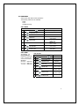
6 ACCOUNTING
Use this menu to gain access to menus that display or reset data for various
types of cash and vend totals. Counts can be viewed by individual items, rows or
as the whole machine.
Historical totals: These are the counts since the initialization of the machine.
They cannot be reset.
Resettable totals: These are totals since the last reset. These can be reset at
any time. You have the option to reset just an item, row or the whole machine.
IIMPORTANT NOTE: Clearing by item and row will only clear the item or row
entered.
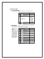
6.3 ACCOUNTING “ALL”
This menu
displays the total
sales value and
total vend count
for the entire
machine.
This includes
satellite
machines.
Confirming clear will
clear ONLY the
resettable counts for
ALL ITEMS.
ACCOUNTING ALL
STEP
DISPLAY
1.
Press Service Mode Button
Motors ( - - )
2.
Press
for Accounting menu
Accounting
3.
Press
for Accounting All menu
4.
Press
Historical Count
Hist. Ct. 10
5.
Press
Historical Cash
Hist. Cash $10.00
6.
Press
Resettable Count
Res. Count 10
7.
Press
Resettable Cash
Res. Cash $10.00
8.
Press
Historical Card
Hist. Card $0.00
9.
Press
Historical 2nd Vends
Hist. 2nd Vends 0
10.
Press
Resettable Card
Res Card $0.00
11.
Press
Resettable 2nd Vends
Res 2nd Vends 0
12.
Press
to clear all Resettable counters
Clear?
13.
Press
to confirm clear
Cleared
14.
Press
four times to exit
All Items
Sales Mode
6.2 ACCOUNTING BY ROW
STEP
DISPLAY
1.
Press Service Mode Button
Motors ( - - )
2.
Press
for Accounting menu
Accounting
3.
Press
then enter Row Number
Row: -*- exit
33
ACCOUNTING BY ROW CONTINUED
DISPLAY
4.
Press
Historical Count by Row
Hist. Ct. 10
5.
Press
Historical Cash by Row
Hist. Cash $10.00
6.
Press
Resettable Count by Row.
7.
Press
Resettable Cash by Row
Reset Cash $10.00
8.
Press
Historical Card by Row
Hist. Card $0.00
9.
Press
Historical 2nd Vends by Row
Hist. 2nd vends 0
10.
Press
Resettable Card by Row
Reset Card $0.00
11.
Press
Resettable 2nd vends by Row
Reset 2nd Vends 0
12.
Press
to clear Resettable Counters
Clear?
13.
Press
to confirm clear
Cleared
Press
to enter another row or press
14.
Reset. Ct. 10
four times to exit
(Sales Mode)
6.1 ACCOUNTING BY ITEM
STEP
DISPLAY
1.
Press Service Mode Button
Motors ( - - )
2.
Press
for Accounting menu
Accounting
3.
Press
then enter Item Number
4.
Press
Historical Count
Hist Ct. 10
5.
Press
Historical Cash
Hist Cash $10.00
6.
Press
Resettable Count
Reset Ct. 10
7.
Press
Resettable Cash
Reset. Cash $10.00
8.
Press
Historical Card
Hist. Card $0.50
9.
Press
Historical 2nd vends
Hist. 2nd vends 2
10.
Press
Resettable Card
Reset Card $0.50
11.
Press
Resettable 2nd vends
Reset 2nd Vends 2
12.
Press
to clear Resettable Counters
Clear?
13.
Press
to confirm clear
Cleared
Press
to enter another Item or
press
four times to exit
14.
Item: --*- exit
(Sales Mode)
34
6.9 SHORT DEX REPORT
With the Short DEX Report feature set to ON the number of DEX-UCS data fields
in a download file is shortened to fields required for machine sales and money
accountability, along with active machine error messages. For a complete list of
included DEX fields please see the GVC DEX Data Field Description document.
STEP
1.
Press Service Mode Button
2.
Press
for Accounting menu
3.
Press
for Short Dex menu
4.
Press
to toggle Short Dex ON/OFF
5.
Press
to save the setting
Press
three times to exit
6.
DISPLAY
Motors ( - - )
Accounting
Short Dex (Current Setting)
*-exit 9-edit
Short Dex (Current Setting)
*-exit 9-edit
# to Save
(Sales Mode)
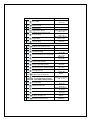
7 ADVANCED OPTIONS
To enter this menu you will be prompted to input a password. The following
options are available:
Max Change
Discount
Programmable POS
Promo Vend
Shutdown
Free Vend Rate
Energy Savings
Exact Change
Motor Pairing
Unconditional Acceptance
7.1 DISCOUNT
This menu accesses the following sub-menus that allow the vending
machine (controller) to charge a different price for selections at different
times or on different days:
Item
Start Time
Value
Row
Day
Enable ON/OFF
All
Stop Time
7.1.3 DISCOUNT “ALL”
STEP
DISPLAY
1.
Press Service Mode Button
Motors ( - - )
2.
3.
Press
for Password menu
Enter Password (default 2314)
Advanced
4.
Press
for Discount menu
Discount
5.
Press
for All Items
Password
All Items (Current Setting)
*- exit 3- edit
35
DISCOUNT “ALL” CONTINUED
DISPLAY
All Items: (Choice Flashing)
*- exit # - save
All Items (New setting)
*- exit 3- edit
6.
Press
to toggle All Items ON/OFF
7.
Press
to save the setting
Press
to return to Discount menu
9.
Press
for Day menu
10.
Press
for All Days
11.
Press
to toggle All Days ON/OFF
12.
Press
to save the setting
13.
Press
to toggle Monday ON/OFF
14.
Mon (New Setting)
Press
to save ON/OFF setting
Press number 3-8 to complete the other days of the week using steps 13 - 14
8.
15.
(To set individual days turn All Days OFF)
Press
two times to return to Discount menu
Press
two times for Start Time menu
Press
then enter Start Time in 24-hr time (HH:MM)
Press
to save new Start Time
Press
to exit to return to Start Time menu
20.
Press
two times for Stop Time menu
21.
Press
then enter Stop Time in 24-hr time (HH:MM)
22.
Press
to save new Stop Time
Press
two times to return to Discount menu
24.
Press
for Discount Value menu
25.
Press
to save new Discount value
Press
two times to return to Discount menu
16.
17.
18.
19.
23.
26.
27.
Press
for Enable Discount menu
28.
Press
to toggle Enable ON/OFF
29.
Press
to save the setting
Press
five times to exit to Sales Mode
30.
Discount
DAY
All Days (Current Setting)
*- exit 1- edit
All Days (Choice Flashing)
*- exit # - save
All Days (New Setting)
*- exit 1- edit
Mon (Choice Flashing)
*- exit 2- edit
Discount
(Current Time)
*- exit # - edit
(New Time)
*- del # - save
(New Time)
*- exit # - edit
Start Time
23:59
*- exit # - edit
(New Time)
*- del # - save
(New Time)
*- exit # -edit
Discount
Discount (Current Value)
*-del #-save
Discount (New Value)
*- exit
Discount
Enable (Current Setting)
*- exit 9- edit
Enable (Choice Flashing)
*- exit # - save
Enable (New Setting)
*- exit 9- edit
Sales Mode
36
7.1.2 DISCOUNT BY ROW
IMPORTANT NOTE: All items (7.1.3) must be turned to OFF.
STEP
DISPLAY
1.
Press Service Mode Button
2.
3.
Press
for Password menu
Enter Password (default 2314)
Advanced
4.
Press
for Discount menu
Discount
5.
Press
for Row menu
Row: - *- exit
6.
Enter row number
7.
Press
8.
Press
9.
Press
once to enter another row or 2 times to go to
Discount menu
to toggle Row ON/OFF
to save the setting
Motors ( - - )
Password
Row XX: (Current Setting)
*- exit 1- edit
Row XX: (Choice Flashing)
*- exit # - save
Row XX: (New Setting)
*- exit 1- edit
Discount
10. Press
to enter Day menu
11. Press
for All Days
All Days (Current Setting)
*- exit 1- edit
to toggle All days ON/OFF
12. Press
(To set individual days turn All Days off)
All Days (Choice Flashing)
*- exit # - save
13. Press
14. Press
15. Press
16.
Press
to save the setting
to toggle Monday ON/OFF
Every Day (New Setting)
*- exit 1- edit
Mon (Choice Flashing)
*-exit 2-edit
Mon (New Setting)
to save the setting
Press number 3-8 to complete the other days of the week using steps 14 - 15
two times to return to Discount menu
17. Press
two times to enter Start Time menu
18. Press
then enter Start Time in 24-hr time (HH:MM)
19. Press
to save new Start Time
20.
DAY
Press
to return to Start Time menu
21. Press
two times to Stop Time menu
22. Press
then enter Stop Time in 24-hr time (HH:MM)
23. Press
to save new Stop Time
Discount
(Current Time)
*-exit #-edit
(New Time)
*-del #-save
(New Time)
*-exit #-edit
Start Time
23:59
*-exit #-edit
(New Time)
*-del #-save
(New Time)
*-exit #-edit
37
DISCOUNT BY ROW CONTINUED
24.
Press
two times to return to Discount menu
25. Press
to enter Discount Value
26. Press
to save the new Discount Value
27.
Press
two times to return to Discount menu
28. Press
for Enable menu
29. Press
to toggle Discount ON/OFF
30. Press
to save the setting
31.
Press
five times to exit
DISPLAY
Discount
Discount (Current Price)
*-del #-save
Discount (New Price)
*- exit
Discount
Enable (Current Setting)
*- exit 9- edit
Enable (Choice Flashing)
*- exit # - save
Enable (New Setting)
*- exit 9- edit
(Sales Mode)
7.1.1 DISCOUNT BY ITEM
IMPORTANT NOTE: All items (7.1.3) must be set to OFF.
STEP
DISPLAY
1.
Press Service Mode Button
Motors ( - - )
2.
3.
Press
for Password Menu
Enter Password (default 2314)
Advanced
4.
Press
for Discount menu
Discount
5.
Press
then enter Item Number
6.
Enter the Item Number
7.
Press
8.
Press
9.
Press
once to enter another item or 2 times to return to
Discount menu
to toggle Item ON/OFF
to save the setting
10.
Press
11.
Press
12.
Press
to toggle All Days ON/OFF
(To set individual days All Days must be OFF)
13.
Press
14.
Press
to enter Day menu
for All Days
to save the setting
to toggle Monday ON/OFF
Password
Item: --*- exit
Item: XXX (Current Setting)
*- exit 1- edit
Item: XXX (Choice Flashing)
*- exit # - save
Item: XXX (New Setting)
*- exit 1- edit
Discount
DAY
All Days (Current Setting)
*- exit 1- edit
All Days (Choice Flashing)
*- exit # - save
All Days (New Setting)
*- exit 1- edit
Mon (Choice Flashing)
*.exit 2-edit
38
DISCOUNT BY ITEM CONTINUED
15.
16.
Press
Mon (New Status)
to save the setting
Press number 3-8 to complete the other days of the week using steps 14 - 15
Press
two times to exit for Discount menu
17.
Press
two times for Start Time menu
18.
Press
then enter Start Time in 24-hr time (HH:MM)
19.
Press
to save the new Start Time
Press
to exit return to Start Time menu
21.
Press
two times to enter Stop Time menu
22.
Press
then enter Stop Time in 24-hr time (HH:MM)
23.
Press
to save the new Stop Time
Press
two times to return to Discount menu
25.
Press
then enter Discount Value
26.
Press
to save the Value setting
Press
two times to return to Discount menu
20.
24.
27.
28.
Press
for the Enable menu
29.
Press
to toggle Enable ON/OFF
30.
Press
to save the setting
Press
five times to exit
31.
DISPLAY
7.2 PROMO VEND
Promotional Vend - This
function allows a free
promotional product to
be given to a customer in
response
to
their
purchase of another
product. The promotional
product is limited to the
next sequential selection
installed in the machine
Examples: 1) Selection
#33 is not installed in the
Discount
(Current Time)
*-exit #-edit
(New Time)
*- exit # - save
(New Time)
*- exit # - edit
Start Time
23:59
*-exit #-edit
(New Time)
*- exit # - save
(New Time)
*- exit # - edit
Discount
Discount (Current Price)
*- del # - save
Discount (New Price)
*- exit
Discount
Enable (Current Setting)
*- exit # - edit
Enable (Choice Flashing)
*- exit # - save
Enable (New Setting)
*- exit # - edit
(Sales Mode)
STEP
1. Press Service Mode Button
2. Press
for Password menu
3. Enter password (default 2314)
4. Press
for Promo Vend menu
5. Press
for Promo Vend setting
6. Press
to toggle ON/OFF
7. Press
to save the setting
DISPLAY
Motors ( - - )
Password
Advanced
Promo Vend
Promo Vend (Current Setting)
*- exit 4- edit
Promo Vend (Choice Flashing)
*- exit # - save
Promo Vend (New Setting)
*- exit 4- edit
39
machine. The purchase
of selection #32 will give
away selection #34; 2)
Purchase selection #53
will give away selection
#54. (Examples only—
you are not limited to
only two promo vends)
PROMO VEND CONTINUED
8. Press
menu
to return to Promo Vend
9. Press
then enter Item Number
10. Press
to toggle ON/OFF
11. Press
12.
Press
to save the setting
DISPLAY
Promo Vend
Item: - - *- exit
Item: XXX (Choice Flashing)
*- exit # - save
Item: XXX (New Setting)
*- exit 1- edit
(Sales Mode)
three times to exit
7.3 FREE VEND RATE
Enter a number from 0-255.
This will set the number of paid vends between free vends.
Example: If set at 5; every 5th vend will be free.
STEP
DISPLAY
1.
Press Service Mode Button
2.
Press
for Password menu
Enter Password (default 2314)
3.
4.
Press
menu
to enter Free Vend Rate
5.
Press
then enter new Rate
6.
Press
to save the setting
Press
three times to exit
7.
Motors ( - - )
Password
Advanced
Free Vend Rate: (Current Rate)
*- exit # - edit
Free Vend Rate: (New Rate)
*- exit #- save
Free Vend Rate: (New Rate)
*- exit #- edit
(Sales Mode)
7.4 EXACT CHANGE
Exact Change - Sets the
coin tube value that will
trigger the display of the
STEP
DISPLAY
1.
Press Service Mode Button
Please
Change
2.
3.
Press
for Password menu
Enter Password (default 2314)
Motors ( - - )
Password
4.
Press
then press
5.
Press
to edit
6.
Press
to save the setting
7.
Press
four times to exit.
Use
Exact
message.
Example: If Exact Change
is set to $5.00. The
Please
Change
Use
Exact
message will
come on when the total of
change available (nickels,
dimes and quarters) in the
coin tubes is at or below
$5.00.
Advanced
Exact Change: $0.00
*- exit # - edit
Exact Change: $1.00
*- exit # - save
Exact Change: $1.00
*- exit #- edit
(Sales Mode)
IMPORTANT NOTE: In software version prior to 8207, if “Uncond. Accept” is set,
for example, at $20.00; exact change will also be $20.00 and cannot be set for a
lower amount.
40
7.4.2 EXACT CHANGE - ALTERNATE RULE
Alternate Change
Rule - This function
prevents a vend from
occurring, flashes the
Please Use Exact
Change message and
will return the established
credit amount, if one or
more of the coin tubes
are too low to give back
the correct change for the
vend.
STEP
1.
Press Service Mode Button
2.
3.
Press
for Password menu
Enter Password (default 2314)
4.
Press
for Exact Change menu
5.
Press
for Alt Rules menu
6.
Press
to toggle ON/OFF
7.
Press
to save the setting
Press
four times to exit.
8.
7.5 UNCONDITIONAL ACCEPTANCE
STEP
Unconditional
Acceptance - Sets
1. Press Service Mode Button
the unconditional
2. Press
for Password menu
acceptance value. All
3. Enter Password (default-2314)
cash box coins or bills
equal to or less than this
Press
for Unconditional
set value will be accepted 4.
Accept menu
even if the changer
5. Press
cannot return an equal
then enter Price
amount of change. When
set to “0.00” all changer
to save the
6. Press
tube coins are accepted.
setting
Bills are accepted once
there is enough change
7.
in the changer to pay
Press
three times to exit.
back the bill type.
DISPLAY
Motors ( - - )
Password
Advanced
Exact Change
Alt Rules (Current Setting)
*-exit 2-edit
Alt Rules (Choice Flashing)
*- exit # - save
Alt Rules (New Setting)
*- exit 2-edit
(Sales Mode)
DISPLAY
Motors ( - - )
Password
Advanced
Uncond Accept: $0.00
*- exit # - edit
Uncond Accept: $5.00
*- del # - save
Uncond Accept: $5.00
*- exit # - edit
(Sales Mode)
The Unconditional Acceptance set value is adjustable but the maximum value is equal to the
largest denomination of currency or coin accepted by the changer or validator.
7.6 MAX CHANGE
Maximum Change
Option This option
prevents change from
being returned to the
customer until the
amount of credit has
been reduced to a value
less than or equal to the
programmed maximum
change limit.
STEP
1. Press Service Mode Button
2. Press
for Password menu
3. Enter Password (default is 2314)
4. Press
menu
for Max Change
for current Max
5. Press
Change setting
DISPLAY
Motors ( - - )
Password
Advanced
Max Change
Max Change (Current Setting)
*- exit 1- edit
41
MAX CHANGE CONTINUED
Note:
The highest value that
can be set for the
maximum price is 655.35
for a scale factor of 1 and
999.95 for a scale factor
of 5.
6. Press
to toggle ON/OFF
7. Press
to save setting
8. Press
amount
then enter dollar
9. Press
to save the setting
10.
Press
DISPLAY
Max Change (Choice Flashing)
*- exit # - save
Max Change (New Setting)
*- exit 1- edit
Max Change: $50.00
*- exit # - save
Max Change
(Sales Mode)
three times to exit
7.7 PROGRAMMABLE POS MESSAGE
These are messages that can be edited. You must first turn ON the default POS
message under the options menu 3.7.
7.7.1 PROGRAMMING the POS MESSAGE
STEP
DISPLAY
1.
Press Service Mode Button
2.
Press
for Password menu
Enter Password (default is 2314)
3.
Motors ( - - )
4.
Press
for Programmable POS menu
5.
Press
for POS setting
6.
Press
to toggle ON/OFF
7.
Press
to save setting
8.
Press
to enter message
Press
;
Press
;
9.
backspace
11.
Advanced
Programmable POS
Programmable POS
(Current Setting)
*- exit 1- edit
Programmable POS
(Choice Flashing)
*- exit # - save
Programmable POS
(New Setting)
*- exit 1- edit
...Enjoy A Snack
; to move cursor to the left
;
; to move cursor to the right
Press
;
;
; to move the cursor from top to
bottom. Once the cursor is in the place you want to
edit press
10.
;
Password
In edit mode
is space key,
is
saves
Press
to save the message
Press
4 times to exit
(Sales Mode)
42
7.7.2 AUXILLARY MESSAGES
STEP
DISPLAY
1.
Press Service Mode Button
Motors ( - - )
2.
Press
Configuration
for Configuration menu
3.
Press
to toggle the language to auxiliary
4.
Press
to save the setting
Press
two times to exit the Configuration menu
6.
Press
and enter password (default is 2314)
7.
Press
for Programmable POS menu
8.
Press
to enter auxiliary messages
9.
Press
to toggle through messages.
Press
to edit the selected message.
5.
10.
Press
;
Press
;
;
Language: Auxiliary
*- exit # - save
Language: Auxiliary
*- exit 1- edit
Motors ( - - )
Advanced
Programmable POS
(Message Choice)
*- exit #- edit 1-next
(Message Choice)
*- exit #- edit 1-next
; to move cursor to the left
;
; to move cursor to the right
Press
;
;
to move the cursor from top to
bottom. Once the cursor is in the place you want to
edit press
In edit mode
is space key,
is backspace;
saves
11.
Press
12
Press
three times to exit; or Press
step 10. to edit more messages
to save the setting
and follow
(Sales Mode)
IMPORTANT NOTE: To edit the messages the language must be in set to Auxiliary in
mode 4.4.
43
GVC KEY/CHARACTER MAPPING
Lower case key map (un-shifted):
KEY
1
2
3
4
5
6
7
8
9
0
FUNCTIONS
SHIFT (FUNCTION CHANGE)
a
b
c
d
e
f
g
h
i
j
k
l
m
n
o
p
q
r
t
u
v
w
x
y
SPACE
s
z
Upper case key map (shifted):
KEY
1
2
3
4
5
6
7
8
9
0
FUNCTIONS
SHIFT (FUNCTION CHANGE)
A
B
C
D
E
F
G
H
I
J
K
L
M
N
O
P
Q
R
T
U
V
W
X
Y
SPACE
S
Z
Symbol key map (shifted):
KEY
1
2
3
4
5
6
7
8
9
0
FUNCTIONS
SHIFT (FUNCTION CHANGE)
!
.
?
‘
”
,
;
:
$
@
%
*
¥
+
/
=
[
‘
(
[
{
SPACE
=
)
44
7.7.3 TIME DISPLAY
This option will display the time and date. Programmable POS does not
have to be “ON” for this to work.
STEP
DISPLAY
1.
Press Service Mode Button
Motors ( - - )
2.
Press
3.
Enter Password (default is 2314)
for Advanced menu
4.
Press
for Programmable POS menu
5.
Press
for Time Display menu
6.
Press
to toggle ON/OFF
7.
Press
to save the setting
Press
four times to exit
8.
Advanced
Advanced
Programmable POS
Time Display: (Current Setting)
*- exit 4- edit
Time Display: (Choice Flashing)
*- exit # - save
Time Display: (New Setting)
*- exit 4- edit
(Sales Mode)
7.8 SHUTDOWN
This option allows the controller to shut down a range of selections or the
entire machine based on four (4) time-of-day intervals. If the time falls within
one of these intervals and the entire machine has been selected for shutdown
then the message VENDING OPERATION TO RESUME AT hh.mm is displayed.
If a range of selections has been chosen for shutdown that does not
encompass the entire machine, the same message displays once every time
the customer makes a selection that falls within the range.
IMPORTANT NOTE: The correct time and date must be set so that the
SHUTDOWN intervals work correctly. Refer to page 15. Also, for any given
day these four time intervals may overlap one another. For each interval,
the machine (controller) can be programmed from no days up to every
day of the week on which the specified shutdown time intervals are active.
7.8.3 SHUTDOWN ALL
STEP
DISPLAY
1.
Press Service Mode Button
2.
3.
Press
for Password menu
Enter Password (default is 2314)
Advanced
4.
Press
for Shutdown menu
Shutdown
5.
Press
for Interval1 (
6.
Press
for All Items
7.
Press
to toggle ON/OFF
Motors ( - - )
for Interval 2, etc.)
Password
Interval1
All Items: (Current Setting)
*- exit 3- edit
All Items: (Choice Flashing)
*- exit # - save
45
SHUTDOWN ALL CONTINUED
8. Press
9.
Press
10. Press
to save setting
to return to Interval1
to enter Day Menu
to toggle All Days ON/OFF
11. Press
(To program individual days turn Every day OFF)
DISPLAY
All Items: (New Setting)
*- exit 3- edit
Interval1
Day
All Days (Choice Flashing)
*- exit # - save
All Days (Current Setting)
*- exit 1- edit
Monday (Choice Flashing)
13. Press
to toggle ON/OFF
*- exit # - save
Monday (New Setting)
14. Press
to save the setting
*-exit 2-edit
Press number 3-8 to complete the other days of the week using steps 13-14
12. Press
15.
Press
to save the setting
two times to return to Interval1 menu
16. Press
for Start Time menu
17. Press
for Current Time setting
18. Press
then enter Start Time in 24-hr time (HH:MM)
19. Press
to save the Start Time
20.
Press
to return to Start Time menu
21. Press
two times to enter Stop Time menu
22. Press
then enter Stop Time in 24-hr time (HH:MM)
23. Press
to save the Stop Time
24.
Press
two times to return to Interval menu
Press
to toggle Lighting ON/OFF
25. Lighting ON – turns off lights during a shutdown
Lighting OFF – leaves lights on during a shutdown
26. Press
to save the setting
27. Press
for Shutdonw Enable menu
28. Press
to toggle ON/OFF
29. Press
to save the setting
30.
31.
Press
two times to edit Interval 2-4
Press
three times to exit to sales mode
Interval1
Start Time
(Current Time)
*- exit # - edit
(New Time)
*- del # - save
(New Time)
*- exit # - edit
Start Time
23:59
*-exit #-edit
(New Time)
*- del # - save
(New Time)
*- exit # - edit
Interval1
Lighting (Choice Flashing)
*- exit # - save
Lighting (New Setting)
*- exit 8- edit
Enable (Current Setting)
*- exit 9- edit
Enable (Choice Flashing)
*- exit #- save
Enable (New Setting)
*- exit 9- edit
Shutdown
(Sales Mode)
46
7.8.2 SHUTDOWN BY ROW
STEP
DISPLAY
1.
Press Service Mode Button
2.
Press
for Password menu
Enter Password (default is 2314)
Password:
4.
Press
for Shutdown menu
Shutdown
5.
Press
for Interval1 (
Interval1
6.
Press
to set a Row
7.
Enter a Row
8.
Press
9.
Press
10.
Press
to enter another Row or press
2 times to return to Interval menu
11.
Press
12.
Press
to toggle All Days ON/OFF
(To program individual days turn every day OFF)
13.
Press
to save the setting
Press
two times to exit
3.
14.
15.
16.
Motors ( - - )
for Interval 2, etc.)
to toggle Row ON/OFF
to save the setting
to enter Day menu
Press
two times to for Start Time menu
18.
Press
then enter Start Time in 24-hr time (HH:MM)
19.
Press
to save the setting
Press
to return to Start Time menu
21.
Press
two times to enter Stop Time menu
22.
Press
then enter Stop Time in 24-hr time (HH:MM)
23.
Press
to save the setting
Press
two times to exit to Interval menu
Press
for Shutdown Enable menu
24.
25.
Row: - *- exit
Row: XX (Current Setting)
*- exit 1- edit
Row: XX (Choice Flashing)
*- exit # - save
Row: XX (New Setting)
*- exit 1- edit
Interval1
Day
All Days (Choice Flashing)
*- exit # - save
All Days (New Setting)
*- exit 1- edit
Monday (Choice Flashing)
Press
to toggle Monday ON/OFF
*- exit # - save
Monday (New Setting)
Press
to save the setting
*-exit 2-edit
Press number 3-8 to complete the other days of the week using steps 14-15
17.
20.
Advanced
Interval1
(Current Time)
*- exit # - edit
(New Time)
*- del # - save
(New Time)
*- exit # - edit
Start Time
23:59
*-exit #-edit
(New Time)
*- del # - save
(New Time)
*- exit # - edit
Interval1
Enable (Current Setting)
*- exit 9- edit
47
SHUTDOWN BY ROW CONTINUED
26.
Press
to toggle ON/OFF
27.
Press
to save the setting
Press
two times to edit Interval 2-4
Press
five times to exit to sales mode
28.
29.
DISPLAY
Enable (Choice Flashing)
*- exit #- save
Enable (New Setting)
*- exit 9- edit
Shutdown
(Sales Mode)
7.8.1 SHUTDOWN BY ITEM
STEP
DISPLAY
1.
Press Service Mode Button
2.
3.
Press
for Password menu
Enter Password (default is 2314)
Advanced
4.
Press
for Shutdown menu
Shutdown
5.
Press
for Interval1 (
Interval1
6.
Press
for Item menu
7.
Enter Item Number
8.
Press
to toggle ON/OFF
9.
Press
to save the setting
10.
Press
menu
to enter another item or press
11.
Press
to enter Day Menu
12.
Press
to toggle All Days ON/OFF
(To program individual days turn Every day OFF)
13.
Press
to save the setting
Press
two times to return to Interval menu
17.
Press
two times for Start Time menu
18.
Press
then enter Start Time in 24-hr time (HH:MM)
19.
Press
to save the setting
14.
15.
16.
Motors ( - - )
Password
for Interval 2, etc.)
Item: --*- exit
Item: XXX (Current Setting)
*- exit 1- edit
Item: XXX (Choice Flashing)
*- exit # - save
Item: XXX (New Setting)
*- exit 1- edit
2 times for Interval1
Interval1
Day
All Days (Choice Flashing)
*- exit # - save
All Days (New Setting)
*- exit 1- edit
Monday (Choice Flashing)
Press
to toggle Monday ON/OFF
*- exit # - save
Monday (New Setting)
Press
to save the setting
*-exit 2-edit
Press number 3-8 to complete the other days of the week using steps 14-15
Interval1
(Current Time)
*- exit # - edit
(New Time)
*- del # - save
(New Time)
*- exit # - edit
48
SHUTDOWN BY ITEM CONTINUED
20.
Press
Start Time
to return to Start Time menu
21.
Press
two times to enter Stop Time menu
22.
Press
then enter Stop Time in 24-hr time (HH:MM)
23.
Press
to save the setting
Press
two times to exit to Interval menu
25.
Press
for Shutdown Enable menu
26.
Press
to toggle ON/OFF
27.
Press
to save the setting
Press
two times to edit Interval 2-4
Press
three times to exit
24.
28.
29.
DISPLAY
23:59
*-exit #-edit
(New Time)
*- del # - save
(New Time)
*- exit # - edit
Interval1
Enable (Current Setting)
*- exit 9- edit
Enable (Choice Flashing)
*- exit #- save
Enable (New Setting)
*- exit 9- edit
Shutdown
(Sales Mode)
7.9 ENERGY SAVINGS
This function allows you to set a NON-health safety machine to run at a
higher than normal temperature during set times.
IMPORTANT NOTE: Energy Savings runs OUTSIDE of the HS Standards. There are
two programmable intervals.
STEP
1.
Press Service Mode Button
2.
Press
for Password menu
Enter Password (Default is 2314)
3.
4.
Press
for Energy Savings menu
5.
Press
for Interval1(to edit Interval 2, Press
6.
Press
for Day menu
7.
Press
to toggle All Days ON/OFF
(To program individual days turn every day OFF)
8.
9.
10.
11.
12.
DISPLAY
Motors ( - - )
Password
Advanced
Energy Savings
)
Interval1/ or Interval2
Day
All Days (Choice Flashing)
*- exit # - save
All Days (New Setting)
*- exit 1- edit
Monday (Choice Flashing)
Press
to toggle Monday ON/OFF
*- exit # - save
Monday (New Setting)
Press
to save the setting
*-exit 2-edit
Press number 3-8 to complete the other days of the week using steps 9-10
Press
to save the setting
Press
two times to return to Interval menu
Press
two times for Start Time menu
Interval1
(Current Time)
*- exit # - edit
49
ENERGY SAVINGS CONTINUED
13.
Press
then enter Start Time in 24-hr time (HH:MM)
14.
Press
to save the setting
Press
to return to Start Time menu
16.
Press
two times to enter Stop Time menu
17.
Press
then enter Stop Time in 24-hr time (HH:MM)
18.
Press
to save the setting
Press
two times to return to Interval menu
20.
Press
to enter Storage Temp (default is 62ºF)
21.
Press
to set Storage Temp (available range: 36ºF to 62ºF)
22.
Press
to save the setting
Press
two times for INTERVAL menu
15.
19.
23.
24.
Press
to toggle Lighting ON/OFF
Lighting ON-turns off lights during Energy Savings.
Lighting OFF- leaves lights On during Energy Savings
25.
Press
to save setting
Press
two times to return to Interval menu
27.
Press
for Energy Savings Enable menu
28.
Press
to toggle enable ON/OFF
29.
Press
to save the setting
Press
five times to exit to Sales mode
26.
30.
DISPLAY
(New Time)
*- del # - save
(New Time)
*- exit # - edit
Start Time
23:59
*-exit #-edit
(New Time)
*- del # - save
(New Time)
*- exit # - edit
Interval1
Storage (Current temp)F
*- exit 7- edit
Storage (Choice Flashing)F
*- exit # - save
Storage (New temp)F
*- exit 7- edit
Interval1
Lighting (Choice Flashing)
*- exit # - save
Lighting (New Setting)
*- exit 8- edit
Interval1
Enable (Current Setting)
*- exit 9- edit
Enable (Choice Flashing)
*- exit #- save
Enable (New Setting)
*- exit 9- edit
(Sales Mode)
50
7.0 MOTOR PAIRING
This function is so two motors, on the same shelf, can be ran at the same time.
This allows for wide or bigger items to be vended.
Setting Dual Motors
STEP
DISPLAY
1.
Press Service Mode Button
Motors ( - - )
2.
3.
Press
for Password menu
Enter Password (default-2314)
4.
Press
5.
Enter the first motor number
6.
Press
enter the 2nd motor number
Press
two times to add another pair or
7.
press
Password
for Motor Pairing menu
Advanced
Pair - - *-exit
Pair 012 to - - *-exit #-add
Pair 012 to 013
*-exit #-save
(Sales mode)
five times to exit to sales mode
nd
If first motor is even, 2 motor must be odd. Motors 12 and 13 will turn at the same
time to vend a large product. Motor 13 will need to be a motor that runs backward
from motor 12. If first motor is odd, 2nd motor must be even. Both motors have to be
on same shelf.
8 TEST MOTOR
Use this menu to test vend individual motors. The selection displays with the
test vend. If a test vend attempt on a particular motor fails, controller beeps.
STEP
DISPLAY
1.
Press Service Mode Button
2.
Press
3.
Press selection number and wait
Motors ( - - )
Item - - *-exit
Item 010
*-del
4.
Repeat step 3 for other selections.
5.
Press
for Test Motor menu
(Sales Mode)
two times to exit.
9 TEST ALL MOTORS
This menu tests vend all motors. The selection displays the test vend. If a test
vend attempt on a particular motor fails, then the controller beeps. Satellite
machines are also included in the test.
IMPORTANT
STEP
DISPLAY
NOTE:
1. Press Service Mode Button
Motors ( - - )
Pressing
at any
time stops the test.
2.
3.
Press
and wait.
The motor selection number
displays while it is being tested.
Press
two times to exit.
Item
Item 010
(Sales Mode)
51
0 DIAGNOSTICS MENU
0.1 SYSTEM DIAGNOSTIC
This menu is used to perform a self-diagnostics check and display results.
STEP
DISPLAY
1.
Press Service Mode Button
Motors ( - - )
2.
Press
Diagnostic...
3.
4.
for Diagnostic menu
Press
to start test
Press
four times to exit.
Checksum
Temp Sensor
Optical Vend
Coin Acceptor
Bill Validator
Card Reader1
Card Reader2
Tests Completed
(Sales Mode)
0.2 TEST RELAY
Testing of Relays - This menu provides functions that allow the operator to
test the operation of the individual relay lines 1 through 6.
RELAY1 - Refrigeration
Compressor.
RELAY2 - Evaporator Fan
RELAY3 – Defrost heater
Upon exit from the function
the corresponding relay
control line reverts to a
state that is dependent on
the controller's normal
relay control algorithm.
RELAY4 – controls the
upper zone heater when
configured as MZF
STEP
DISPLAY
1.
Press Service Mode Button
Motors ( - - )
2.
Press
for Diagnostic menu
Diagnostics
3.
Press
for Relays menu
4.
Press
to toggle Relay 1 ON/OFF
Relay 1 ON/OFF
5.
Press
to toggle Relay 2 ON/OFF
Relay 2 ON/OFF
6.
Press
to toggle Relay 3 ON/OFF
Relay 3 ON/OFF
7.
Press
to toggle Relay 4 ON/OFF
Relay 4 ON/OFF
8.
Press
to toggle Relay 5 ON/OFF
Relay 5 ON/OFF
9.
Press
to toggle Relay 6 ON/OFF
Relay 6 ON/OFF
Press
four times to exit
10.
Relays
(Sales Mode)
52
0.3 LOG
Note: Engineering data download for service technician ONLY!
STEP
DISPLAY
1.
Press Service Mode Button
Motors ( - - )
2.
Press
for Diagnostics menu
Diagnostics
3.
Press
for Log
Press
three times to exit
4.
Log
(Sales Mode)
0.4 COIN REJECT RATE
This feature tracks the percentage of coins that have been rejected by the coin
mech. This resets when in accounting “ALL” has been cleared.
STEP
DISPLAY
1.
Press Service Mode Button
Motors ( - - )
2.
Press
for Diagnostics menu
Diagnostics
3.
Press
to view percentage
Press
three times to exit
4.
Coin Rej. Rate 10%
Sales Mode
0.5 BILL REJECT RATE
This feature tracks the percentage of bills that have been rejected by the bill
validator. This resets when in accounting “ALL” has been cleared.
STEP
DISPLAY
1.
Press Service Mode Button
Motors ( - - )
2.
Press
for Diagnostics menu
Diagnostics
3.
Press
to view percentage
Press
three times to exit
4.
Bill Rej. Rate 20%
Sales Mode
0.6 IVEND ALIGNED
When a machine is equipped with the iVend™ optical vend sensors this feature
provides an audible and visual indication of when the vend sensors are aligned
or not aligned correctly.
If the iVend™ sensors are blocked or not aligned a continuous series of audible
beeps is heard and the display shows NO, until the sensors are properly
aligned.
STEP
DISPLAY
1.
Press Service Mode Button
Motors ( - - )
2.
Press
for Diagnostics menu
Diagnostics
3.
Press
to check iVend alignment
iVend aligned NO/OK
53
0.7 ADVANED DIAGNOSTICS
0.7.1 REFRIG LOG
This feature allows data on the current state of the refrigeration sensors, relays,
timer and error conditions to be output to the serial port.
STEP
DISPLAY
1.
Press Service Mode Button
Motors ( - - )
2.
Press
Diagnostics
3.
4.
Press
for Password menu
Enter Password (default-2314)
5.
Press
for Refrigeration Log status
6.
Press
to toggle ON/OFF
7.
Press
to save the setting
Press
four times to exit
8.
for Diagnostics menu
Password:
Log
Refrig Log (Current Status)
*- exit 1- edit
Refrig Log (Choice Flashing)
*- exit # - save
Refrig Log (New Status)
*- exit 1- edit
(Sales Mode)
0.7.2 DAQ LOG
This feature sends display vibration sensor values. For Engineering use only.
STEP
DISPLAY
1.
Press Service Mode Button
Motors ( - - )
2.
Press
Diagnostics
3.
4.
Press
for Password menu
Enter Password (default-2314)
5.
Press
for DAQ Log
6.
Press
three times to exit
for Diagnostics menu
Password:
Log
DAQ Log (after a few seconds, display
changes to Log)
(Sales Mode)
0.7.3 STS LOG
This feature sends the current space to sales settings to the serial port.
For Engineering use only.
STEP
DISPLAY
1.
Press Service Mode Button
Motors ( - - )
2.
Press
Diagnostics
3.
4.
Press
for Password menu
Enter Password (default-2314)
5.
Press
6.
Press
for Diagnostics menu
for STS
three times to exit
Password:
Log
StS (after a few seconds, display
changes to Log)
(Sales Mode)
54
0.7.4 HEALTH SAFETY TEST
The HEALTH SAFETY feature prevents the sale of perishable food if the air
temperature inside the Satellite Food Vendor compartment rises above the Health
Safety temperature limit for more than 15 minutes. The factory default for health
safety limit is automatically set when the refrigeration configuration is set. The
perishable products being vended must match the refrigeration configuration.
Important Note: Make sure that the Health Safety setting is enabled prior to
starting this test. See Service Mode 4.9.1 below.
1.
Close the door and wait 75 minutes for the temperature stabilize
2.
Simulate Warm Temperature
a. Open the door
b. Locate the sensor at the back of the cabinet above the top tray.
c. Remove the mounting screw; place the sensor in a cup of warm
water.
d. Enable HS Test software setting in control board service mode.
See Below.
e. Close the door.
3.
Perform Test
a.
b.
c.
d.
4.
Press
on the host machine numerical keypad to check the
temperature.
Wait until the temperature is above the upper health safety limit of
41ºF for 15 minutes.
Try to vend a product from the Satellite Food Vendor.
If the health safety is working properly the vend should fail; the
machine should have automatically been disabled by the controller
board.
After Test is Completed
a. Open the Satellite Food Vendor door
b. Remove the sensor from the cup of water and put the sensor back in
place.
c. Close the door and time how long it takes for the Satellite Food
Vendor to get below the refrigeration set point. . Cold should be
below the set point within 30 minutes.
When HS test ON (HS Door switch override ON) is saved in Service mode, and
the machine door is closed the Health Safety Activation Delay Time is set to the
15 minute value rather than the extended 30 minutes for Cold and 75 minutes
for Frozen that is allowed after a normal door closure. To allow for multiple door
open/closes and door close debounce the HS test mode is active for 3 minutes
after "HS test ON" is set in Service Mode, so that if the door is opened/closed
multiple times the 15 minute timer would be set again and still be used. Also,
when "HS test ON" is set the refrigeration OFF timer should also be reset at this
time so that when it is time for the minimum off time to expire the "HS test ON"
mode is also cleared. Once the door is closed Health Safety feature now
functions as if the machine door had been closed for a long period of time and
any temperature value over the HS limit, for the refrigeration mode in use,
causes the normal 15 minute HS limit timer to start a count and if the
temperature limit is exceeded for 15 minutes disables vending from the
machine. Refrigeration Modes affected are: Cold, Frozen and MZF
55
STEP
DISPLAY
1.
Press Service Mode Button
Motors ( - - )
2.
Press
Diagnostics
3.
4.
Press
for Password menu
Enter Password (default-2314)
5.
Press
for Health Safety test
6.
Press
to toggle ON/OFF
7.
Press
to save the setting
Press
four times to exit
8.
Press
for Diagnostics menu
Password:
Log
HS Test (Current Setting)
*- exit 4- edit
HS Test (Choice Flashing)
*- exit # - save
HS Test (New Setting)
*- exit 4- edit
(Sales Mode)
in Sales Mode to see current teperatures and “HS Test” message
0.7.5 CAN/BOTTLE DROP SENSOR BIAS
With the can/bottle drop sensor bias feature, the value of the internal controller
setting for the vend detection can be viewed. This feature requires the machine
to have a can/bottle drop sensor attached.
Caution: This feature is only used on closed front can and bottle vending
machines.
STEP
DISPLAY
1.
Press Service Mode Button
Motors ( - - )
2.
Press
Diagnostics
3.
4.
Press
Password menu
Enter Password (default-2314)
Password:
Log
5.
Press
for Drop Bias menu
Drop Bias
6.
Press
to view the setting
Drop Bias 0-125
Press
five times to exit
8.
for Diagnostics menu
(Sales Mode)
0.8 DOOR ALERT
This feature allows for an alarm to sound if the machine door is left open, on a
machine that has a door switch.
STEP
1.
Press Service Mode Button
2.
Press
for Diagnostics menu
3.
Press
for Door Alert setting
4.
Press
to toggle ON/OFF
5.
Press
to save the setting
Press
three times to exit
6.
DISPLAY
Motors ( - - )
Diagnostics
Door Alert (Current Setting)
*- exit 8- edit
Door Alert (Choice Flashing)
*- exit # - save
Door Alert (New Setting)
*- exit 8- edit
(Sales Mode)
56
0.9 MANUAL DEFROST
This feature allows a machine to begin a manual defrost of a refrigeration
system. The sequence continues after the machine door is closed and the
machine is in the sales mode.
STEP
1.
Press Service Mode Button
2.
Press
for Diagnostics menu
3.
Press
for Manual Defrost setting
4.
Press
to toggle ON/OFF
5.
Press
to save the setting
Press
three times to exit
6.
DISPLAY
Motors ( - - )
Diagnostics
Manual Defrost (Current Setting)
*- exit 9- edit
Manual Defrost (Choice Flashing)
*- exit # - save
Manual Defrost (New Setting)
*- exit 9- edit
(Sales Mode)
0.0 ELEVATOR
With the Elevator feature set to ON the Elevator controller commands are sent
from the GVC control board to the Elevator control board. This allows for the
elevator tray motor and baffle commands, along with monitoring all related
sensors. Caution: This feature requires the machine to have the Elevator
features present from the factory.
0.0.1.1 ELEVATOR BOARD SOFTWARE REVISION
This menu displays the current information sent to the GVC control board from
the Elevator control board. This information will include the Elevator control
board model number and software revision. This information is also reported in
the full DEX data download.
STEP
DISPLAY
1.
Press Service Mode Button
Motors ( - - )
2.
Press
for Diagnostics menu
Diagnostics
3.
Press
for Peripherals menu
Peripherals
4.
Press
for Elevator menu
5.
Press
for Software Version
Press
four times to exit
6.
Elevator
SW vEC 4218988.XXX
*-exit
(Sales Mode)
57
0.0.1.2 NUMBER OF TRAYS
With the Elevator feature set to ON the number of trays in the machine can be
verified with this mode.
Note: The main door must be closed to perform this function.
STEP
DISPLAY
1.
Press Service Mode Button
Motors ( - - )
2.
Press
Diagnostics
3.
Press
Peripherals
4.
Press
Elevator
5.
Press
e.g. Found 5 Rows
*-exit 1-start
6.
Press
to start – the elevator will
search for trays.
e.g. Finding 5 Rows
*-exit
7.
At Completion
e.g. Found 5 Rows
*-exit 1-start
8.
Press
3 times to exit
(Sales Mode)
0.0.1.3 BAFFLE OPEN/CLOSED
With the Elevator feature set to ON the Elevator machine sliding anti-cheat
Baffle door can be OPEN or CLOSED. In the OPEN position the vend space
between the glass and the product trays is open for the elevator tray to move to
any product tray. The Product Delivery door is also closed and locked when the
Baffle is OPEN. When the Baffle is CLOSED the Product Delivery door of the
machine is opened after the Elevator moves to the bottom position in the
machine.
Note: The main door must be closed to perform this function.
IMPORTANT: Do not attempt to open the main door with the baffle
CLOSED, this can cause severe damage.
STEP
DISPLAY
1.
Press Service Mode Button
Motors ( - - )
2.
Press
for Diagnostics menu
Diagnostics
3.
Press
for Peripherals menu
Peripherals
4.
Press
for Elevator menu
Elevator
5.
Press
for Baffle status
Baffle (Current Status)
1-open 2-closed *-exit
6.
Press
to close the baffle
2 – Closing (Flashes)
7.
At completion
Baffle Closed
1-open 2-closed *-exit
8.
Press
1 – Opening (Flashes)
9.
At completion
10.
Press
to open the baffle
3 times to exit
Baffle Open
1-open 2-closed *-exit
(Sales Mode)
58
0.0.2 AUTO-DOOR MOTOR
The function of the Auto-Door motor is to automatically open the delivery door
after each vend. This makes it easier for people to get the product.
How to get Auto-Door motor to run
The way to get the Auto-door motor to run is to do a motor count once the
Auto-door motor has been plugged in.
Auto-Door Test – Opens and closes the Delivery Lift box product door and
indicates if the control board detects the motor cam switch to be in the correct
position.
STEP
DISPLAY
1.
Press Service Mode Button
Motors ( - - )
2.
Press
for Diagnostics menu
Diagnostics
3.
Press
for Peripherals menu
Peripherals
4.
Press
for Auto Door status
5.
Press
to open the delivery door
6.
At completion
7.
Press
8.
At completion
9.
Press
to close the delivery door
4 times to exit
Auto Door (Current Status)
1-open 2-closed *-ext
Auto Door Closed
(Flashes)
Auto Door Open
1-open 2-closed *-ext
Auto Door Open
(Flashes)
Auto Door Closed
1-open 2-closed *-ext
(Sales Mode)
NOTE: The display may show “Unknown” while the Auto Door is moving
to the “Open” or “Closed” position. If the control board can’t determine an
Auto Door motor cam position, the “Unknown” message will also appear.
IMPORTANT: If the control board cannot determine the Auto Door position
when the sales mode is entered the machine will be placed out of service.
0.0.3 DELIVERY LIFT TEST
STEP
DISPLAY
1.
Press Service Mode Button
Motors ( - - )
2.
Press
for Diagnostics menu
Diagnostics
3.
Press
for Peripherals menu
4.
Press
for Delivery Lift status
5.
Press
to raise the Delivery Lift
Peripherals
Lift (Current Status)
1-open 2-closed *-exit
Lift Down
(Flashes)
59
DELIVERY LIFT TEST CONTINUED
6.
At completion
7.
Press
8.
At completion
9.
Press
DISPLAY
Lift Up
1-open 2-closed *-ext
Lift Up
(Flashes)
Lift Down
1-open 2-closed *-ext
to lower the Delivery Lift
(Sales Mode)
4 times to exit
NOTE: The display may show “Lift Unknown” while the Delivery Lift is
moving to the up or down position. If the control board can’t determine a
lift motors cam position the “Lift Unknown” message will also appear.
IMPORTANT: Do not attempt to run the Delivery Lift Test diagnostic if the
Delivery Lift plate may be jammed or appears with one end near the Delivery lift
sensors and the other end near the bottom of the Delivery Box. Manually
correct this issue before running the test. Contact Vendnet Service at 1-800-8334411 for assistance.
0.0.6 LIFT OPTICS ALIGN
This indicates if the Delivery Lift Sensors are functioning and aligned so that
they can detect when a product is lifted to the correct height. The Green LED
on the lift optics board (located behind the iVend Red LED sensor board) will
also be illuminated when sensors are aligned.
STEP
DISPLAY
1.
Press Service Mode Button
Motors ( - - )
2.
Press
for Diagnostics menu
Diagnostics
3.
Press
for Peripherals menu
Peripherals
Press
for Lift Optics status
Lift Opt Align: (Current Status)
XXXXXms
Press
5 times to exit
4.
9.
(Sales Mode)
CUSTOMER LEAD THROUGH MESSAGES
The following messages are affected by the language selection and are stored
in the controller memory.
MESSAGE 1
English
Italian
Dutch
Spanish
Danish
French
German
Turkish
Auxiliary
YOU ARE GETTING HUNGRY TIME TO ENJOY A SNACK
GRAZIE
DANK U
GRACIAS
TAK
MERCI
VIEL DANK
ACIKIYOR MUSUNUZ? ATISTIRMA ZAMANI
ENJOY A SNACK NOW [maximum length: 40]
60
MESSAGE 2
English
Spanish
French
Italian
German
Danish
Dutch
Turkish
Auxiliary
PLEASE INSERT MORE MONEY
POR FAVOR DEPOSITE MAS DINERO
MONTANT INSUFFISANT INTRODUISEZ D'AUTRES PIECES
PER FAVORE INTRODURRE PIU SOLDI
INDKAST FLERE PENGE
MEHR GELD EINWERFEN
MEER GELD IN WERPEN
LUTFEN DAHA\nPARA ATINIZ
[maximum length: 30]
English
Spanish
French
Italian
German
Danish
Dutch
Turkish
Auxiliary
PLEASE USE EXACT CHANGE
POR FAVOR DEPOSITE CANTIDAD EXACTA
FAITES L'APPOINT S’IL VOUS PLAIT
PER FAVORE INTRODURRE I PRECISI SOLDI
ABGEZAHLTES GELD EINWERFEN
INDKAST AFTALTE PENGE
AFGEPAST GELD IN WERPEN
PARA USTU\n VERMEZ
[maximum length: 30]
English
Spanish
French
Italian
German
Danish
Dutch
Turkish
Auxiliary
OUT OF SERVICE
FUERO DE SERVICIO
DEMANDEZ LE RESPONSABLE
PER FAVORE CHIAMARE SERVIZIO
English
Spanish
French
Italian
German
Danish
Dutch
Turkish
Auxiliary
PLEASE MAKE ANOTHER SELECTION
SELECIONE OTRO PRODUCTO
FAITES UNE AUTRE SELECTION
FARE UNA ALTRE SCELTA
ANDERE WARE WAHLEN
VAELG ANDEN VARE
ANDERE KEUZE MAKEN
LUTFEN BASKA\nSECIM YAPINIZ
[maximum length: 25]
MESSAGE 3
MESSAGE 4
BITTE KUNDENDIENST RUFEN
TILKALD SERVICEMONTOR
SERVICEDIENST BELLEN
SERVIS DISI
[maximum length: 25]
MESSAGE 5
MESSAGE 6:
English
Italian
Dutch
Spanish
Danish
French
German
Turkish
Auxiliary
THANK YOU …Enjoy!
GRAZIE
DANK U
GRACIAS
TAK
MERCI
VIEL. DANK
TESEKKUR
[maximum length: 40]
61
MESSAGE 7
English
Italian
Dutch
Spanish
Danish
French
German
Turkish
Auxiliary
DISCOUNT AVAILABLE
DISCOUNT AVAILABLE
DISCOUNT AVAILABLE
DESCUENTO DISPONIBLE
DISCOUNT AVAILABLE
DISCOUNT AVAILABLE
DISCOUNT AVAILABLE
INDIRIM IMKANI
[maximum length: 40]
MESSAGE 8
English
Italian
Dutch
Spanish
Danish
French
German
Turkish
Auxiliary
FREE ON US
FREE
*
FREE
**
FREE ***
Only: GRATIS
FREE ****
FREE *****
FREE******
UCRETSIZDIR
[maximum length: 20]
MESSAGE 9
English
Italian
Dutch
Spanish
Danish
French
German
Turkish
Auxiliary
CREDIT
CREDIT
CREDIT
CREDITO
CREDIT
CREDIT
CREDIT
KREDI
[maximum length: 10]
English
Italian
Dutch
Spanish
Danish
French
German
Turkish
Auxiliary
SELECTION
English
Italian
Dutch
Spanish
Danish
French
German
Turkish
Auxiliary
PRICE
PRICE
PRICE
PRECIO
MESSAGE 10
SELECTION
SELECTION
SELECCION
SELECTION
SELECTION
SELECTION
SECIM
[maximum length: 10]
MESSAGE 11
PRICE
PRICE
PRICE
FIYAT
[maximum length: 10]
62
ERROR CODE MESSAGES
Troubleshoot error code messages with the table below.
GVC2
Message
Possible Actions
Message
Description
CONTROL BOARD ERRORS
[VMC] [OK]
Control board
diagnostic test. Ok
or Good indicates
no active errors.
[VMC xxxx]
Where xxxx is
message
shown below.
Diagnostic Test
error present
[Settings
Reset]
Control board
settings reset to
defaults. Displayed
after software
updates.
If a software upgrade has just been
done change control board settings
and prices as desired. Check control
board settings. Cycle power to board
power and recheck error messages.
[Door Switch]
Door switch is seen
as open for greater
than allowed time
Check door switch for correct
operation with door and check door
harness.
[Scale Factor]
There is a conflict
with one or more
MDB settings from
the attached MDB
devices
Review manuals and settings for
MDB devices to make sure they are
compatible.
[Selection
SW]
A keypad selection
button is stuck in the
pressed position.
Determine reason why keypad
button is stuck and correct issue.
[Low AC]
The incoming AC
power is very low
Determine why low AC voltage is
getting to the control board.
[VMC RAM
checksum] or
No Message
A RAM checksum
error indicates that
accounting data or a
control board setting
were in error. The
control board will
use a backup copy
of the data where
possible.
Check the control board settings and
accountability data for correctness.
Cycle power to the control board and
recheck error messages.
For any error condition
troubleshooting please have the
specific machine manual
63
GVC2
Message
Message
Description
Possible Actions
MOTOR ERRORS
No Message
Motors do not have
any errors present.
[Motor ###
xxxx]
Motor error present
from sales mode
vend. [Esc oPEn]
message is for
machines with a
motorized changer
escrow function.
[Motor ###
OPEN]
The motor or
harness has an
open electrical
connection.
Check motor and motor harness for
open connections. Test vend motor.
Replace motor if necessary.
[Motor ###
SHORT]
The motor or
harness has an
electrical short.
Check motor and motor harness for
short. Replace motor if necessary.
[Motor ###
Home Sns]
The motor home
switch was not
detected while the
motor was in
operation. This may
also indicate a
motor JAM
condition.
Check motor type service mode setting,
motor, motor switch and then spiral for
blockage. Test vend selection motor.
Replace motor if necessary.
[Motor ###
Jam]
A motor JAM has
been detected.
Check motor and spiral for blockage.
[Motor ###
ERRORS]
One or more motor
errors have been
detected.
Test vend selection motor and
review information on motor open,
short, home switch and jam
conditions.
[Motor Under
Voltage]
The detected motor
voltage is not high
enough to run the
selection motors.
Test vend selection motor for correct
operation. Replace Motor. Replace
Board
64
GVC2
Message
Message
Description
Possible Actions
TEMPERATURE SENSOR ERRORS
No Message
or [REFRIG
xxxx]
Refrigeration
temperature sensor
test.
[REFRIG
Sensor #
Open]
A Temperature
sensor or harness is
considered to have
an open electrical
connection. Where
"#" is sensor
number
Check sensor and sensor harness
for open connections. Check for
sensor readings. Replace sensor if
necessary
[REFRIG
Sensor #
Short]
A temperature
sensor or harness is
considered to have
an electrical short.
Where "#" is sensor
number.
Check sensor and sensor harness
for shorted connections. Check for
sensor readings. Replace sensor if
necessary
[REFRIG
Health Safety]
The cabinet
temperature and
time limits for food
health safety have
been exceeded.
Check sensor readings and sensor
harness for shorted connections.
Check for sensor readings. Replace
sensor if necessary
DROP SENSOR ERRORS
Fail: [VMC
Drop Sensor]
The can and bottle
delivery sensor for
closed front
machines is not
detected.
Check sensor and sensor harness
for open connections. Check for
sensor readings. Replace sensor if
necessary.
Pass: No
Message
OPTICAL VEND SENSOR ERRORS
[Optical
Sensor Error]
The iVend optical
delivery for glass
front machines is
blocked, out of
alignment or not
detected.
Check sensor and sensor harness
for open connections. Check for
sensor readings. Replace sensor if
necessary.
65
GVC2
Message
Message
Description
Possible Actions
COIN CHANGER ERRORS
[Coin Mech
xxxxx] or [OK]
Fail: [Coin
Mech xxxxx]
where xxxx is
message
below
[Comm]
Control board does
not have
communication with
the coin
mechanism.
Check MDB Harness to changer.
Check for power on changer, See
changer service manual.
[TubeSns]
The coin
mechanism has
reported a tube
sensor error.
See changer service manual.
[Inlet]
The coin mechanism
has reported an
acceptor blockage
See changer service manual.
[Tube Jam]
The coin
mechanism has
reported a tube
payout error.
Check changer tubes. See changer
service manual.
[ROM]
The coin
mechanism has
reported a program
memory error
See changer service manual.
[Excess Esc]
The coin
mechanism has
reported that a large
number of coin
escrow requests
have occurred
Check changer escrow lever
position. See changer service
manual.
[Coin Jam]
The coin
mechanism has
reported that a coin
is jammed in the
coin path.
Check changer coin path. See
changer service manual.
66
GVC2
Message
Message
Description
Possible Actions
[Low Accept]
The control board
has seen a low
acceptance rate on
coins.
Review inserted coins. See changer
service manual.
[Accpt Disc]
The coin
mechanism has
reported that the
coin validation
acceptor is
disconnected.
Re-connect changers' acceptor. See
changer service manual.
[Route Err]
The coin
mechanism reported
that a coin did not
follow the correct
path.
Check changer coin path. See
changer service manual.
Pass: [OK] or
No message
BILL VALIDATOR ERRORS
[Bill Val
xxxxx] or [OK]
Fail: [Bill Val
xxxxx] where
xxxx is
message
below.
[Comm]
Control board does
not have
communication with
the bill validator.
Check MDB Harness to validator.
Check for power on validator. See
validator service manual.
[Stack Full]
The bill validator
reports that the
stacker is full of
bills.
Check bill stacker box for bills. See
validator service manual.
[Motor Err]
The bill validator
reports that a
validator motor
error has occurred
See validator service manual.
67
GVC2
Message
Message
Description
Possible Actions
[Jam]
The bill validator
reports a bill is stuck
in the bill path.
Check validator bill path for bills. See
validator service manual.
[ROM]
The bill validator
reports a program
memory error.
See validator service manual.
[Stack Open]
The bill validator
reports a bill box is
open or not
installed.
Check bill stacker box for open lid.
See validator service manual.
[Sensor Err]
The bill validator
reports a sensor
error.
See validator service manual.
CARD READER 1 ERRORS
[Card rdr1
xxxxx] or [OK]
Then
Fail: [Card
rdr1 xxxxx]
where xxxx is
message
below or
reader error
code
Card Reader
Address
[Comm]
Control board does not
have communication
with the card reader.
[Err]
The card reader
reports an error.
CARD READER 2 ERRORS
[Card rdr2
xxxxx] or [OK]
Then
Fail: [Card
rdr2 xxxxx]
where xxxx is
message
below or
reader error
code
[Comm]
[Err]
Control board does
not have
communication with
the card reader.
The card reader
reports an error.
68
GVC2
Message
Message
Description
Possible Actions
DELIVERY LIFT ERRORS
1.
[Lift Optic
Error]
Lower I-Vend optical
sensor/s is/are not
functioning
correctly.
2.
3.
1.
[Optic Vend
Error]
Upper I-Vend optical
sensor/s is/are not
functioning
correctly.
2.
3.
1.
[Lift Motor
Open]
An electrical issue
with one or both of
the Lift Motors.
2.
3.
1.
2.
[Auto Door
Open]
An electrical issue
with the Auto Door
Motor.
3.
4.
5.
Check that the Green LED on
the control board for the lower IVend sensors is lit and steady.
If the Green LED is not lit check
for correct alignment and that all
connections to control/sensor
boards are secure/good.
If the Green LED fails to light
replace each board starting with
the control board for the lower IVend sensors.
Check that the Red LED on the
Upper I-Vend hinge side board
is lit and steady.
If The Red LED is not lit check
for correct alignment and that all
connections to control/sensor
boards are secure/good.
If Red LED fails to light replace
the pair of upper I-Vend boards.
Do a “Motor Count”, the first
number total displayed include
the:
a) Coin return Motor
b) Delivery Lift Motor
c) RH Bin Floor Lift Motor
d) LH Bin Floor Lift Motor
After a short delay the number
should reduce by 4 if all the
above are correctly detected.
Check that the wiring to each of
the motors/switches are correct
and secure.
Power cycle the controller and
observe both motors, one
should move a little which
signifies it is good. Replace the
motor that does not move.
Manually operate to check that
the mechanism is free and is not
binding-up.
Check that the wiring to the
motor/switch is correct and
secure.
Check the adjustment of the
index switch.
Replace switch/lever and adjust
correctly.
Replace motor.
69
GVC2
Message
Title
Description
ELEVATOR ERROR CODES
EFL 1
EFL 2
EFL 3
EFL 4
EFL 5
EFL 6
Elevator Position
Vend (EPVD)
Failed.
Lock switch 1 and 2
both high (invalid
condition).
Baffle close (EBCL)
failed to complete.
Baffle open (EBOP)
failed to complete.
Elevator position
standby (EPSB)
failed.
Elevator shelf
position (ESELx)
failed.
EFL 7
Motor fails to move.
EFL 8xy
Shelf Number
Mismatch
EFL 9
Delivery door
opened
unexpectedly.
EFL 98
Command out of
sequence
EFL 99
At top limit switch.
Failed to get to the Vend position
following a position vend command.
Logically both slide switches can
never be operated at the same time.
Failed to close the security baffle
following a “close baffle” command.
Failed to open the security baffle
following an “open baffle” command.
Failed to get to the standby position
following a “position standby”
command.
Failed to get to the required shelf
position following a position shelf
command.
No motor movement for a period of 1
second, as determined by the dual
encoder signals.
A mismatch of shelf numbers
between the VMC controller &
Elevator Controller after a reset
sequence (ERST).
E.G. EFL8-04_05 = 4 shelves were
identified by the Elevator controller
when it was told there are 5. Both
numbers will always be 2 digit.
EFL8-00_05 would mean no shelves
were identified which would indicate
there is a sensor or wiring failure.
Should the delivery door be opened
outside of a vend cycle the elevator
will be immediately sent to the
“vend” position and an ELF9 will be
reported. The VMC controller will
then issue a go to standby command
once the delivery door has been
closed.
Will be returned as part of the
elevator status reply if any other
command is issued other than a
“reset” or “position standby”
command at power up.
Will be returned as part of the
elevator status reply if a command is
issued if the elevator is stationary at
the top limit for any reason.
70
ELEVATOR TROUBLE SHOOTING
Problem
Symptoms
Possible Cause/s
ELEVATOR TROUBLESHOOTING
The
Elevator or
Baffle do
not move or
operate
Baffle does
not open
after a vend
No activity from the
elevator system
ERROR CODES
NONE
At the end of a vend,
after the item has
been retrieved, the
baffle does not reOPEN for 1 minute.
During the 1 minute
delay the message
“Please Remove
Your Product” is
shown and the
beeper sounds
every 10 seconds
Delivery Door Optical Switch (J4 of
Elevator Control Board, Black, Brown &
White wires, GREEN LED D11 is lit when
the delivery door is CLOSED):
1. Check that the delivery door is fully
closed
2. Move the elevator down to unlock
the delivery door and check VERY
slowly that the delivery door is
completely free in its motion and
closes under its own weight – VERY
IMPORTANT
3. Check that the GREEN LED D1 on
the elevator control board is lit
indicating the delivery door is
CLOSED
4. Check that the optical switch
actuator plate mounted to the back
of the delivery door is not blocking
the switch when the door is
CLOSED. Adjust plate such that
LED D11 comes ON when the door
1
3
is /4“– /8” away from the closed
position at the bottom edge of the
door.
5. Check the inline connection next to
the switch
6. Check the connection to the
Elevator Control Board at J4.
7. Faulty Optical Switch, replace
Delivery Door Optical Switch (J4 of
Elevator Control Board, Black, Brown &
White wires, GREEN LED D11 is lit when
the delivery door is CLOSED):
1. Check that the GREEN LED D11
goes out when the delivery door is
opened by 3/8” at the bottom edge.
2. If necessary adjust the actuator
plate as described in d) above
3. Faulty Optical Switch, replace
ERROR CODES
NONE
71
Problem
Symptoms
Power cycle with
main door closed
and baffle fully
open/home –
Elevator is driven to
VEND and stops,
baffle cycles out/in 3
times and stops
Out of
Service
ERROR CODES
EFL 2
EFL 99
Power cycle with
main door closed
and the baffle partly
out or fully closed –
Elevator ascends
and hits baffle and
stops
Possible Cause/s
UPPER Lock Slide Switch (Orange &
Black wires, GREEN LED D8 is lit when
switch is not actuated):
1. Check that the lock slide is not
hitting the underside of the delivery
door because it is not closing
correctly
2. Move the elevator up to give good
access & visibility of the lock-slide.
Operate the lock slide very slowly by
hand to ensure the motion is free
and both switches are correctly
actuated.
3. Check connection at switch
4. Check connection at elevator control
board
5. Switch open-circuit/damaged,
replace switch
ERROR CODES
EFL 2
EFL 5
EFL 99
Out of
Service
Power cycle with
main door closed Elevator attempts to
drive very slowly to
STANDBY; if baffle
is partly out or
closed the elevator
is stopped/stalled,
GVC attempts 2
further resets which
fail.
If the baffle is fully
in/open the elevator
will continue to the
top limit switch and
stop.
UPPER Lock Slide Switch (Orange &
Black wires, GREEN LED D8 is lit when
the switch is not actuated):
1. Switch contacts do not open when
lever is actuated, replace switch
2. Wiring to switch is ‘short-circuit’
ERROR CODES
EFL 5
72
Problem
Out of
Service
Symptoms
Power cycle with
elevator in
STANDBY, baffle
fully open and main
door closed – The
baffle closes,
elevator is moved to
PARK then back to
STANDBY, baffle
cycles a couple of
times and stops in
an unpredictable
position, then there
4 short pulses which
move the baffle by
approx. 1/16” each
time, then the
system goes out of
service
ERROR CODES
EFL 2
EFL 5
EFL 99
Possible Cause/s
LOWER Lock Slide Switch (Yellow &
Black wires, GREEN LED D9 is lit when
the switch is not actuated):
1. Check connection at switch
2. Check connection at elevator control
board
3. Switch open-circuit/damaged,
replace switch
Power cycle with
elevator is in the
STANDBY position
and the baffle is
partly out - The
baffle is pulsed 4
times, then a 2
second delay and
then a 2nd set of 4
pulses before going
out of service again.
ERROR CODES
EFL 99
Out of
Service
Power cycle with
elevator is in the
STANDBY position
– The baffle closes,
then a dull ‘thump’
can be heard and
the timing belt may
jump a couple of
times on the pulleys
as the elevator is
LOWER Lock Slide Switch (Yellow &
Black wires, GREEN LED D8 is lit when
the switch is not actuated):
1. Switch contacts do not open when
lever is actuated
2. Wiring to switch is ‘short-circuit’
73
Problem
Symptoms
Possible Cause/s
driven against the
bottom stop/end
limit.
ERROR CODES
EFL 1
Out of
Service
The elevator
successfully
completes the
initializing sequence
after a power cycle
or main door
closure.
When attempting to
do a vend the
elevator goes to the
top limit switch and
stops. GVC sends a
reset and
subsequently there
could be varying
errors. GVC
continues to issue
resets several times
before the system is
ultimately put out of
service.
Elevator Motor Encoder #1 (Green/White
wire):
1. Check connection at motor
2. Check connection at elevator control
board
3. Faulty/Open Circuit encoder, replace
motor
ERROR CODES
EFL 5
EFL 8xy
EFL 99
Out of
Service
In most cases the
initializing sequence
after a power cycle
or door closure is
successful; the
elevator sometimes
stops momentarily
halfway down. When
attempting a vend it
is possible that an
item is dispensed
from the shelf
without the elevator
moving, as if the
elevator functionality
had not been
Elevator Motor Encoder #2 (Red/White
wire):
1. Check connection at motor
2. Check connection at elevator control
board
3. Faulty/Open Circuit encoder, replace
motor
74
Problem
Symptoms
Possible Cause/s
enabled. After this a
nd
2 vend can result
in nothing vending
and the elevator
starts to pulse
between PARK &
STANDBY
indefinitely.
ERROR CODES
EFL 3
EFL 4
EFL 5
EFL 6
EFL 7
EFL 8xy
EFL 99
Out of
Service
Power cycle with
elevator is in the
STANDBY position
with main door
closed – Baffle
closes, elevator
moves to VEND
then immediately to
STANDBY, baffle
opens and elevator
starts moving up
and stops shortly
after (top of elevator
is approx. 1” above
the bottom of the
glass)
Elevator Motor Encoders #1 & #2
(Green/White & Red/White wires):
1. Check connections at motor
2. Check connections at elevator
control board
3. Faulty encoders, replace motor
ERROR CODES
EFL 7
Out of
Service
Power cycle with
elevator is in the
STANDBY position
with main door
closed - Elevator
moves to PARK,
baffle moves out,
elevator moves to
VEND, elevator
moves to
STANDBY, baffle
moves in, elevator to
PARK then
Top Limit Switch (Orange & Black wires,
GREEN LED D13 is lit when the switch is
not actuated):
1. Check connections at switch
2. Check connections at elevator
control board
3. Switch open-circuit/damaged,
replace switch
75
Problem
Symptoms
Possible Cause/s
immediately to
STANDBY.
The above is
repeated 2 further
times before system
goes out of service.
ERROR CODES
EFL 8-00_05
EFL 99
Out of
Service
Power cycle with
elevator is in the
STANDBY position
with main door
closed – The
elevator & baffle
perform normal
process at the start
of the initializing
sequence, then the
elevator ascends
and hits frame at top
and stops/stalls.
2 furthers resets are
issued which results
in the same
behavior, elevator
remains at top of
frame and goes out
of service.
Condition is
recoverable from a
reset command.
Top Limit Switch (Orange & Black wires,
GREEN LED D13 is lit when the switch is
not actuated):
1. Switch contacts do not open when
lever is actuated, replace switch
2. Wiring to switch is ‘short-circuit’
ERROR CODES
EFL 7
Out of
Service
Power cycle with
elevator is in the
STANDBY position
with main door
closed – The
elevator moves to
PARK, the baffle
moves out to close.
Baffle remains
closed and elevator
ascends and hits
baffle and stops.
GVC issues 2
Baffle ‘Open/Front’ Limit Switch (Yellow
& Black wires, GREEN LED D10 is lit
when the switch is not actuated):
1. Check connections at switch
2. Check connections at elevator
control board
3. Switch open-circuit/damaged,
replace switch
76
Problem
Symptoms
Possible Cause/s
further resets and
the above is
repeated before
going out of service
ERROR CODES
EFL 7
EFL 8-00_05
Out of
Service
Power cycle with
elevator is in the
STANDBY position
with main door
closed - Elevator
moves to PARK, the
baffle moves out
and cycles 2 times
then stops.
GVC issues 2
further resets and
the above is
repeated before
going out of service
Baffle ‘Open/Front’ Limit Switch (Yellow
& Black wires, GREEN LED D10 is lit
when the switch is not actuated):
1. Switch contacts do not open when
lever is actuated, replace switch
2. Wiring to switch is ‘short-circuit’
ERROR CODES
EFL 5
Baffle does
not move
Power cycle with
elevator is in the
STANDBY position
with main door
closed – The
elevator moves to
PARK, the baffle
doesn’t move, the
elevator goes to
VEND and then to
TOP LIMIT and
returns to PARK –
the reset is
successful.
Baffle ‘Closed’ (rear) Limit Switch
(Orange & Black wires, GREEN LED
D11 is lit when the switch is not
actuated):
1. Check connections at switch
2. Check connections at elevator
control board
3. Switch open-circuit/damaged,
replace switch
ERROR CODES
NONE
77
Problem
Out of
Service
Symptoms
Power cycle with
elevator is in the
STANDBY position
with main door
closed – The
elevator goes to
PARK, the baffle
operates
continuously for 3 ½
cycles.
GVC issues 2
further resets and
the above is
repeated before
going out of service
Possible Cause/s
Baffle ‘Closed’ (rear) Limit Switch
(Orange & Black wires, GREEN LED
D11 is lit when the switch is not
actuated):
1. Switch contacts do not open when
lever is actuated, replace switch
2. Wiring to switch is ‘short-circuit’
ERROR CODES
EFL 1
Baffle
Closes
when a
selection is
made
Power cycle with
elevator is in the
STANDBY position
with main door
closed – System will
reset/initialize
normally. When
making a vend the
baffle is closed and
the elevator is sent
to VEND and
“Please Remove
Your Product” is
displayed; this
simulates an item
blocking the I-vend.
I-Vend Input to GVC J8_Pin 5 (White
wire):
1. The RED LED on the ‘hinge’ side IVend board should be lit & steady?
2. I-Vend is physically blocked in the
elevator tray
3. The I-Vend red filter lens is/are dirty
4. The sides of the elevator tray have
been bent/misaligned
5. One or both of the I-Vend boards
is/are faulty or damaged, replace as
pair.
ERROR CODES
NONE
Machine
may be
‘Free
Vending’
The elevator
successfully
completes the
initializing sequence
after a power cycle
or main door closure
– System will
dispense the item
from the shelf but it
will not be detected
I-Vend Input to GVC J8_Pin 5 (White
wire):
1. The RED LED on the ‘hinge’ side IVend board should be lit and when
something blocks/interrupts the
array it will go out
2. There is a short circuit in the wiring
3. One or both of the I-Vend boards
is/are faulty or damaged, replace as
pair.
78
Problem
Symptoms
Possible Cause/s
and credit will not be
deducted, the
display shows
“Please Select
Another Selection”.
The elevator returns
to STANDBY and
item/s can be
retrieved by
unlocking the
delivery door by
pressing the # key
ERROR CODES
NONE
The
Elevator or
Baffle do
not move or
operate
Out of
Service
The
Elevator
does not
operate
No activity from the
elevator system
ERROR CODES
NONE
Main Door Switch (GVC J3, Elevator
Control Board J5, Black/Yellow &
Black/Green wires):
1. Check that the striker plate in the top
RH corner of the cabinet is actuating
the Door Switch mounted on the
door
2. Check that GVC J3 is connected
and secure
3. Check that Elevator Control Board
J5 is connected and secure
Elevator in ‘Standby’
– Power-up/close
main door and
nothing happens
1.
ERROR CODES
EFL 1
2.
Elevator in ‘Park’ Power-up/close
main door, if baffle is
fully open it will
close, then nothing.
ERROR CODES
EFL 1
Elevator in ‘Vend’ Power-up/close
door.
a) If baffle is fully
open it cycles 1 ¾
times, this repeats 3
Check the 6-Way connector to the
elevator motor is fully
home/connected
Set-up a voltage meter to take a
24VDC reading across pins 1 & 3 of
the elevator motor connector on the
elevator control board (P2), remove
one wire from the main door switch,
and a few seconds later after check
to see if there is a voltage output to
the motor.
If there is 24-30VDC, replace the
motor
If no voltage replace the control
board
79
Problem
Symptoms
Possible Cause/s
times and then
stops.
b) If baffle is not fully
open it will not
move.
ERROR CODES
EFL 1
EFL 5
1.
2.
Out of
Service
(Only
relates to
Elevator
Control
Boards
with pre
Revision
1.07
Firmware)
Power-up/close
main door with
elevator & Baffle in
any position, ‘Out of
Service’ is displayed
after a few
moments, nothing
happens.
3.
ERROR CODES
ELEVATOR COMM
4.
Check the DEX harness connecting
between the GVC & Elevator control
boards are properly connected
If there is a card system with its DEX
plug engaged with the DEX socket
in the machine, ensure that it is
pushed fully home (if it is partially
out the transmit line is shorted to
ground)
Having eliminated the above two
possibilities, with the machine
switched ON, remove the power
connector (P1) from the elevator
board, leave for 20 seconds, then
reconnect and close door
If this solves the problem then the
elevator firmware should be
upgraded to > Rev 1.07
Having eliminated the above three
possibilities, first replace the
elevator control board, then the GVC
80
QUICK REFERENCE GUIDE
81
The contents of this publication are presented for informational purposes only, and while every effort has been made to ensure their accuracy, they
are not to be construed as warranties or guarantees, express or implied, regarding the products or services described herein or their use or
applicability. We reserve the right to modify or improve the designs or specifications of such products at any time without notice.
VendNet™
165 North 10th Street
Waukee, Iowa 50263
United States of America
USA & Canada
Service
(800) 833-4411
Parts
(888) 259-9965
Email
Web Site
International
(515) 274-3641
[email protected]
www.vendnetusa.com
82
P/N 4215507 RevD