1
PCI Expansion Unit
for Fujitsu M10/SPARC M10 Systems
Service Manual
Manual Code: C120-E683-09EN
December 2014
Copyright © 2007, 2014, Fujitsu Limited. All rights reserved.
Oracle and/or its affiliates provided technical input and review on portions of this material.
Oracle and/or its affiliates and Fujitsu Limited each own or control intellectual property rights relating to products and technology described in this document, and such products,
technology and this document are protected by copyright laws, patents, and other intellectual property laws and international treaties.
This document and the product and technology to which it pertains are distributed under licenses restricting their use, copying, distribution, and decompilation. No part of such
product or technology, or of this document, may be reproduced in any form by any means without prior written authorization of Oracle and/or its affiliates and Fujitsu Limited, and
their applicable licensors, if any. The furnishings of this document to you does not give you any rights or licenses, express or implied, with respect to the product or technology to
which it pertains, and this document does not contain or represent any commitment of any kind on the part of Oracle or Fujitsu Limited or any affiliate of either of them.
This document and the product and technology described in this document may incorporate third-party intellectual property copyrighted by and/or licensed from the suppliers to
Oracle and/or its affiliates and Fujitsu Limited, including software and font technology.
Per the terms of the GPL or LGPL, a copy of the source code governed by the GPL or LGPL, as applicable, is available upon request by the End User. Please contact Oracle and/or its
affiliates or Fujitsu Limited. This distribution may include materials developed by third parties. Parts of the product may be derived from Berkeley BSD systems, licensed from the
University of California.
UNIX is a registered trademark of The Open Group.
Oracle and Java are registered trademarks of Oracle and/or its affiliates.
Fujitsu and the Fujitsu logo are registered trademarks of Fujitsu Limited.
SPARC Enterprise, SPARC64, SPARC64 logo and all SPARC trademarks are trademarks or registered trademarks of SPARC International, Inc. in the United States and other
countries and used under license.
Other names may be trademarks of their respective owners.
If this is software or related documentation that is delivered to the U.S. Government or anyone licensing it on behalf of the U.S. Government, the following notice is applicable:
U.S. GOVERNMENT END USERS: Oracle programs, including any operating system, integrated software, any programs installed on the hardware, and/or documentation, delivered
to U.S. Government end users are "commercial computer software" pursuant to the applicable Federal Acquisition Regulation and agency-specific supplemental regulations. As such,
use, duplication, disclosure, modification, and adaptation of the programs, including any operating system, integrated software, any programs installed on the hardware, and/or
documentation, shall be subject to license terms and license restrictions applicable to the programs. No other rights are granted to the U.S. Government.
Disclaimer: The only warranties granted by Oracle and Fujitsu Limited, and/or any affiliate in connection with this document or any product or technology described herein are those
expressly set forth in the license agreement pursuant to which the product or technology is provided.
EXCEPT AS EXPRESSLY SET FORTH IN SUCH AGREEMENT, ORACLE OR FUJITSU LIMITED, AND/OR THEIR AFFILIATES MAKE NO REPRESENTATIONS OR WARRANTIE
S OF ANY KIND (EXPRESS OR IMPLIED) REGARDING SUCH PRODUCT OR TECHNOLOGY OR THIS DOCUMENT, WHICH ARE ALL PROVIDED AS IS, AND ALL EXPRESS
OR IMPLIED CONDITIONS, REPRESENTATIONS AND WARRANTIES, INCLUDING WITHOUT LIMITATION ANY IMPLIED WARRANTY OF MERCHANTABILITY, FITNESS
FOR A PARTICULAR PURPOSE OR NONINFRINGEMENT, ARE DISCLAIMED, EXCEPT TO THE EXTENT THAT SUCH DISCLAIMERS ARE HELD TO BE LEGALLY INVALID.
Unless otherwise expressly set forth in such agreement, to the extent allowed by applicable law, in no event shall Oracle or Fujitsu Limited, and/or any of their affiliates have any
liability to any third party under any legal theory for any loss of revenues or profits, loss of use or data, or business interruptions, or for any indirect, special, incidental or
consequential damages, even if advised of the possibility of such damages.
DOCUMENTATION IS PROVIDED "AS IS" AND ALL EXPRESS OR IMPLIED CONDITIONS, REPRESENTATIONS AND WARRANTIES, INCLUDING ANY IMPLIED
WARRANTY OF MERCHANTABILITY, FITNESS FOR A PARTICULAR PURPOSE OR NON-INFRINGEMENT, ARE DISCLAIMED, EXCEPT TO THE EXTENT THAT SUCH
DISCLAIMERS ARE HELD TO BE LEGALLY INVALID.
Copyright © 2007, 2014, Fujitsu Limited. Tous droits réservés.
Oracle et/ou ses affiliés ont fourni et vérifié des données techniques de certaines parties de ce composant.
Oracle et/ou ses affiliés et Fujitsu Limited détiennent et contrôlent chacun des droits de propriété intellectuelle relatifs aux produits et technologies décrits dans ce document. De
même, ces produits, technologies et ce document sont protégés par des lois sur le droit d’auteur, des brevets, et d'autres lois sur la propriété intellectuelle et des traités internationaux.
Ce document, le produit et les technologies afférents sont exclusivement distribués avec des licences qui en restreignent l'utilisation, la copie, la distribution et la décompilation.
Aucune partie de ce produit, de ces technologies ou de ce document ne peut être reproduite sous quelque forme que ce soit, par quelque moyen que ce soit, sans l'autorisation écrite
préalable d'Oracle et/ou ses affiliés et de Fujitsu Limited, et de leurs éventuels concédants de licence. Ce document, bien qu'il vous ait été fourni, ne vous confère aucun droit et
aucune licence, exprès ou tacites, concernant le produit ou la technologie auxquels il se rapporte. Par ailleurs, il ne contient ni ne représente aucun engagement, de quelque type que
ce soit, de la part d'Oracle ou de Fujitsu Limited, ou des sociétés affiliées de l'une ou l'autre entité.
Ce document, ainsi que les produits et technologies qu'il décrit, peuvent inclure des droits de propriété intellectuelle de parties tierces protégés par le droit d’auteur et/ou cédés sous
licence par des fournisseurs à Oracle et/ou ses sociétés affiliées et Fujitsu Limited, y compris des logiciels et des technologies relatives aux polices de caractères.
Conformément aux conditions de la licence GPL ou LGPL, une copie du code source régi par la licence GPL ou LGPL, selon le cas, est disponible sur demande par l'Utilisateur Final.
Veuillez contacter Oracle et/ou ses affiliés ou Fujitsu Limited. Cette distribution peut comprendre des composants développés par des parties tierces. Des parties de ce produit
pourront être dérivées des systèmes Berkeley BSD licenciés par l'Université de Californie.
UNIX est une marque déposée de The OpenGroup.
Oracle et Java sont des marques déposées d'Oracle Corporation et/ou de ses affiliés.
Fujitsu et le logo Fujitsu sont des marques déposées de Fujitsu Limited.
SPARC Enterprise, SPARC64, le logo SPARC64 et toutes les marques SPARC sont utilisées sous licence et sont des marques déposées de SPARC International, Inc., aux Etats-Unis et
dans d'autres pays.
Tout autre nom mentionné peut correspondre à des marques appartenant à leurs propriétaires respectifs.
Si ce logiciel, ou la documentation qui l'accompagne, est concédé sous licence au Gouvernement des Etats-Unis, ou à toute entité qui délivre la licence de ce logiciel ou l'utilise pour le
compte du Gouvernement des Etats-Unis, la notice suivante s'applique :
U.S. GOVERNMENT END USERS: Oracle programs, including any operating system, integrated software, any programs installed on the hardware, and/or documentation, delivered
to U.S. Government end users are "commercial computer software" pursuant to the applicable Federal Acquisition Regulation and agency-specific supplemental regulations. As such,
use, duplication, disclosure, modification, and adaptation of the programs, including any operating system, integrated software, any programs installed on the hardware, and/or
documentation, shall be subject to license terms and license restrictions applicable to the programs. No other rights are granted to the U.S. Government.
Avis de non-responsabilité : les seules garanties octroyées par Oracle et Fujitsu Limited et/ou toute société affiliée de l'une ou l'autre entité en rapport avec ce document ou tout
produit ou toute technologie décrits dans les présentes correspondent aux garanties expressément stipulées dans le contrat de licence régissant le produit ou la technologie fournis.
SAUF MENTION CONTRAIRE EXPRESSEMENT STIPULEE AU DIT CONTRAT, ORACLE OU FUJITSU LIMITED ET/OU LES SOCIETES AFFILIEES A L'UNE OU L'AUTRE
ENTITE DECLINENT TOUT ENGAGEMENT OU GARANTIE, QUELLE QU'EN SOIT LA NATURE (EXPRESSE OU IMPLICITE) CONCERNANT CE PRODUIT, CETTE
TECHNOLOGIE OU CE DOCUMENT, LESQUELS SONT FOURNIS EN L'ETAT. EN OUTRE, TOUTES LES CONDITIONS, DECLARATIONS ET GARANTIES EXPRESSES OU
TACITES, Y COMPRIS NOTAMMENT TOUTE GARANTIE IMPLICITE RELATIVE A LA QUALITE MARCHANDE, A L'APTITUDE A UNE UTILISATION PARTICULIERE OU A
L'ABSENCE DE CONTREFACON, SONT EXCLUES, DANS LA MESURE AUTORISEE PAR LA LOI APPLICABLE. Sauf mention contraire expressément stipulée dans ce contrat,
dans la mesure autorisée par la loi applicable, en aucun cas Oracle ou Fujitsu Limited et/ou l'une ou l'autre de leurs sociétés affiliées ne sauraient être tenues responsables envers une
quelconque partie tierce, sous quelque théorie juridique que ce soit, de tout manque à gagner ou de perte de profit, de problèmes d'utilisation ou de perte de données, ou
d'interruptions d'activités, ou de tout dommage indirect, spécial, secondaire ou consécutif, même si ces entités ont été préalablement informées d'une telle éventualité.
LA DOCUMENTATION EST FOURNIE "EN L'ETAT" ET TOUTE AUTRE CONDITION, DECLARATION ET GARANTIE, EXPRESSE OU TACITE, EST FORMELLEMENT
EXCLUE, DANS LA MESURE AUTORISEE PAR LA LOI EN VIGUEUR, Y COMPRIS NOTAMMENT TOUTE GARANTIE IMPLICITE RELATIVE A LA QUALITE MARCHANDE,
A L'APTITUDE A UNE UTILISATION PARTICULIERE OU A L'ABSENCE DE CONTREFACON.
Contents
Preface
xv
Chapter 1
Before Starting Maintenance Work
1
1.1
Warning/Caution Indications
1
1.2
Labels/Tags
1.3
Safety Precautions
1.4
Notes Regarding Static Electricity
1.5
Other Precautions
1.6
Emergency Power Off
1.7
Important Information about the XCP Firmware
2
3
4
5
6
6
1.7.1
Precautions for updating the XCP firmware
7
1.7.2
Notes on using the direct I/O function
1.7.3
How to save/restore the logical domain configuration
7
information and the OpenBoot PROM environment variable
Chapter 2
Understanding the PCI Expansion Unit Components
2.1
Identifying the Names and Locations of Components
2.2
Checking the Status with the LED
Front LEDs on the PCI expansion unit
2.2.2
LEDs on rear of PCI expansion unit
2.2.3
LEDs on link card
3.1
Troubleshooting
17
17
20
2.2.1
Chapter 3
9
21
22
24
27
Suspected Failure Conditions
27
iii
3.2
Determining the Causes of Individual Failures
3.3
Identifying a Failure
3.4
28
3.3.1
Checking the LED indications
3.3.2
Checking error messages
3.3.3
Checking the status
3.3.4
Checking log information
29
29
29
33
Locating the PCI Expansion Unit Requiring Maintenance
Chapter 4
Preparing for Maintenance
Preparing Tools Required for Maintenance
4.2
Understanding Types of Maintenance
35
Maintenance types of the PCI expansion unit
4.2.2
Checking whether the PCI hot plug (PHP) can be used
4.2.3
Checking whether the SR-IOV function is used
Precautions for Maintenance
5.4
57
5.1.1
Releasing the link card using PHP
58
5.1.2
Releasing the link card using physical partition dynamic
57
64
Turning Off the Power to the Physical Partition to Which the PCI
Stopping the Entire System
72
74
5.3.1
Stopping the system with the XSCF command
75
5.3.2
Stopping the system from the operation panel
75
Accessing Components
76
5.4.1
Removing the power cords
5.4.2
Removing the front cover
76
77
Understanding the Preparations for Restoring the System
Mounting the Link Card on the Server
6.1.1
iv
55
Releasing the Link Card from the Server
Chapter 6
6.1
52
56
Expansion Unit Requiring Maintenance Belongs
5.3
36
Understanding the Preparations for Enabling Maintenance
reconfiguration (DR)
5.2
35
4.2.1
Chapter 5
5.1
34
35
4.1
4.3
27
79
Mounting the link card on the server using PHP
PCI Expansion Unit for Fujitsu M10/SPARC M10 Systems Service Manual ・ December 2014
79
79
6.1.2
Mounting the link card on the server using physical partition
dynamic reconfiguration (DR)
6.2
83
Turning On the Power to the Physical Partition to Which the PCI
Expansion Unit Requiring Maintenance Belongs
6.3
6.4
Starting the Entire System
89
6.3.1
Starting the system with the XSCF command
90
6.3.2
Starting the system from the operation panel
91
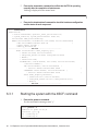
Restoring the chassis of the PCI expansion unit
6.4.1
Installing the power cords
6.4.2
Installing the front cover
Chapter 7
92
Maintaining the PCI Express Cards
Configuration of the PCIe Cards
7.2
Before Maintaining a PCI Express Card
7.4
7.5
91
91
7.1
7.3
88
95
95
7.2.1
Types of maintenance
7.2.2
Maintenance flow
7.2.3
Precautions for installation
7.2.4
Precautions for removal
97
97
98
98
98
Enabling the Removal of a PCI Express Card
7.3.1
Active/hot maintenance
7.3.2
Active/cold maintenance
106
7.3.3
Inactive/hot maintenance
107
7.3.4
Inactive/cold maintenance
7.3.5
System stopped/hot maintenance
7.3.6
System stopped/cold maintenance
Removing a PCI Express Card
98
99
107
108
108
109
7.4.1
Accessing a PCI Express card cassette
109
7.4.2
Removing a PCI Express card cassette
110
7.4.3
Removing a PCI Express card
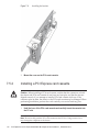
Installing a PCI Express Card
112
114
7.5.1
Installing a PCI Express card
114
7.5.2
Installing a PCI Express card cassette
116
Contents
v
7.5.3
7.6
Restoring the System
117
117
7.6.1
Active/hot maintenance
7.6.2
Active/cold maintenance
121
7.6.3
Inactive/hot maintenance
122
7.6.4
Inactive/cold maintenance
7.6.5
System stopped/hot maintenance
7.6.6
System stopped/cold maintenance
Chapter 8
117
122
Maintaining the Link Board
Configuration of the Link Board
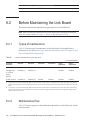
8.2
Before Maintaining the Link Board
8.4
8.5
8.6
8.2.1
Types of maintenance
8.2.2
Maintenance flow
123
125
126
126
126
Enabling the Removal of the Link Board
8.3.1
Active/hot maintenance
8.3.2
Active/cold maintenance
128
8.3.3
Inactive/hot maintenance
128
8.3.4
Inactive/cold maintenance
8.3.5
System stopped/hot maintenance
8.3.6
System stopped/cold maintenance
Removing the Link Board
129
129
130
131
Accessing the link board
131
8.4.2
Removing the link board
132
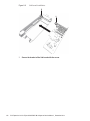
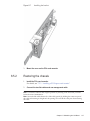
Installing the Link Board
127
127
8.4.1
135
8.5.1
Installing the link board
8.5.2
Restoring the chassis
Restoring the System
123
125
8.1
8.3
vi
Restoring the chassis
135
137
138
8.6.1
Active/hot maintenance
138
8.6.2
Active/Cold maintenance
138
8.6.3
Inactive/hot maintenance
139
8.6.4
Inactive/cold maintenance
139
PCI Expansion Unit for Fujitsu M10/SPARC M10 Systems Service Manual ・ December 2014
8.6.5
System stopped/hot maintenance
8.6.6
System stopped/cold maintenance
Chapter 9
Maintaining the Link Cards
140
143
9.1
Configuration of a Link Card
9.2
Before Maintaining a Link Card
9.3
140
143
9.2.1
Types of maintenance
9.2.2
Maintenance precautions
145
145
145
Enabling the Removal of the Link Card
146
9.3.1
Active/hot maintenance (use of PHP)
9.3.2
Active/hot maintenance (use of DR)
9.3.3
Inactive/hot maintenance
9.3.4
Inactive/cold maintenance
9.3.5
System stopped/hot maintenance
9.3.6
System stopped/cold maintenance
9.4
Removing the Link Card
9.5
Installing the Link Card
9.6
Restoring the System
147
148
148
149
149
150
151
151
9.6.1
Active/hot maintenance (use of PHP)
9.6.2
Active/hot maintenance (use of DR)
9.6.3
Inactive/hot maintenance
9.6.4
Inactive/cold maintenance
9.6.5
System stopped/hot maintenance
9.6.6
System stopped/cold maintenance
Chapter 10
146
152
153
153
154
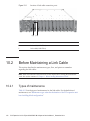
Maintaining the Link Cables
155
155
157
10.1
Configuration of the Link Cable Connection Ports
10.2
Before Maintaining a Link Cable
10.3
10.2.1
Types of maintenance
10.2.2
Maintenance flow
10.2.3
Precautions for replacement
158
158
159
159
Enabling the Removal of a Link Cable
10.3.1
157
Active/hot maintenance
160
161
Contents
vii
10.3.2
Active/cold maintenance
161
10.3.3
Inactive/hot maintenance
162
10.3.4
Inactive/cold maintenance
10.3.5
System stopped/hot maintenance
10.3.6
System stopped/cold maintenance
10.4
Removing a Link Cable
10.5
Installing a Link Cable
10.6
Restoring the System
162
163
163
164
165
166
10.6.1
Active/hot maintenance
10.6.2
Active/cold maintenance
166
10.6.3
Inactive/hot maintenance
167
10.6.4
Inactive/cold maintenance
10.6.5
System stopped/hot maintenance
10.6.6
System stopped/cold maintenance
168
Maintaining the Management Cable
171
Chapter 11
166
167
168
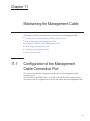
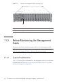
11.1
Configuration of the Management Cable Connection Port
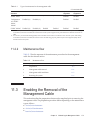
11.2
Before Maintaining the Management Cable
11.3
11.2.1
Types of maintenance
11.2.2
Maintenance flow
172
172
173
Enabling the Removal of the Management Cable
11.3.1
Active/hot maintenance
174
11.3.2
Active/cold maintenance
174
11.3.3
Inactive/hot maintenance
175
11.3.4
Inactive/cold maintenance
11.3.5
System stopped/hot maintenance
11.3.6
System stopped/cold maintenance
175
11.4
Removing the Management Cable
11.5
Installing the Management Cable
11.6
Restoring the System
176
177
177
178
179
11.6.1
Active/hot maintenance
11.6.2
Active/cold maintenance
179
179
viii PCI Expansion Unit for Fujitsu M10/SPARC M10 Systems Service Manual ・ December 2014
173
171
11.6.3
Inactive/hot maintenance
11.6.4
Inactive/cold maintenance
11.6.5
System stopped/hot maintenance
11.6.6
System stopped/cold maintenance
182
Maintaining the Power Supply Units
183
12.1
Configuration of the Power Supply Units
183
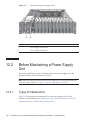
12.2
Before Maintaining a Power Supply Unit
184
Chapter 12
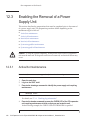
12.3
180
180
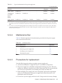
12.2.1
Types of maintenance
12.2.2
Maintenance flow
12.2.3
Precautions for replacement
181
184
185
185
Enabling the Removal of a Power Supply Unit
12.3.1
Active/hot maintenance
12.3.2
Active/cold maintenance
187
12.3.3
Inactive/hot maintenance
188
12.3.4
Inactive/cold maintenance
12.3.5
System stopped/hot maintenance
12.3.6
System stopped/cold maintenance
186
12.4
Removing a Power Supply Unit
12.5
Installing a Power Supply Unit
12.6
Restoring the System
188
189
189
190
191
191
12.6.1
Active/hot maintenance
12.6.2
Active/cold maintenance
193
12.6.3
Inactive/hot maintenance
193
12.6.4
Inactive/cold maintenance
12.6.5
System stopped/hot maintenance
12.6.6
System stopped/cold maintenance
Chapter 13
186
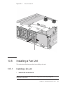
Maintaining the Fan Units
192
194
Configuration of the Fan Units
197
13.2
Before Maintaining a Fan Unit
198
Types of maintenance
13.2.2
Maintenance flow
195
197
13.1
13.2.1
194
198
199
Contents
ix
13.2.3
13.3
13.4
13.5
13.6
Active/hot maintenance
13.3.2
Active/cold maintenance
201
13.3.3
Inactive/hot maintenance
201
13.3.4
Inactive/cold maintenance
13.3.5
System stopped/hot maintenance
13.3.6
System stopped/cold maintenance
Removing a Fan Unit
200
13.4.1
Accessing a fan unit
204
13.4.2
Removing a fan unit
204
Installing a Fan Unit
202
203
205
13.5.1
Installing a fan unit
13.5.2
Restoring the chassis
Restoring the System
202
203
205
206
206
13.6.1
Active/hot maintenance
206
13.6.2
Active/cold maintenance
207
13.6.3
Inactive/hot maintenance
207
13.6.4
Inactive/cold maintenance
13.6.5
System stopped/hot maintenance
13.6.6
System stopped/cold maintenance
Maintaining the PCI Tray
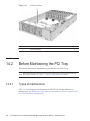
14.2
Before Maintaining the PCI Tray
14.2.1
Types of maintenance
14.2.2
Maintenance flow
208
208
211
212
212
213
Enabling the Removal of the PCI Tray
213
14.3.1
Active/cold maintenance
14.3.2
Inactive/cold maintenance
14.3.3
System stopped/cold maintenance
Removing the PCI Tray
209
211
Configuration of the PCI Tray
14.4
200
13.3.1
14.1
14.3
199
Enabling the Removal of a Fan Unit
Chapter 14
x
Precautions for replacement
214
214
215
216
PCI Expansion Unit for Fujitsu M10/SPARC M10 Systems Service Manual ・ December 2014
14.5
14.6
14.4.1
Accessing the PCI tray
216
14.4.2
Removing the PCI tray
216
14.4.3
Removing the components of the PCI tray
Installing the PCI Tray
218
14.5.1
Installing the components of the PCI tray
14.5.2
Installing the PCI tray
14.5.3
Restoring the chassis
Restoring the System
218
219
Active/cold maintenance
14.6.2
Inactive/cold maintenance
14.6.3
System stopped/cold maintenance
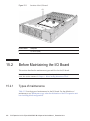
Maintaining the I/O Board
219
219
Configuration of the I/O Board
15.2
Before Maintaining the I/O Board
15.4
15.5
15.6
221
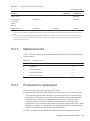
15.2.1
Types of maintenance
15.2.2
Maintenance flow
15.2.3
Precautions for replacement
222
222
223
223
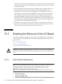
Enabling the Removal of the I/O Board
15.3.1
Active/cold maintenance
15.3.2
Inactive/cold maintenance
15.3.3
System stopped/cold maintenance
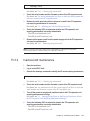
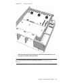
Removing the I/O Board
225
226
227
Accessing the I/O board
227
15.4.2
Removing the I/O board
227
230
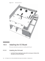
15.5.1
Installing the I/O board
15.5.2
Restoring the chassis
Restoring the System
224
224
15.4.1
Installing the I/O Board
220
221
15.1
15.3
218
218
14.6.1
Chapter 15
218
230
233
234
15.6.1
Active/cold maintenance
234
15.6.2
Inactive/cold maintenance
15.6.3
System stopped/cold maintenance
236
236
Contents
xi
Chapter 16
Maintaining the Fan Backplane
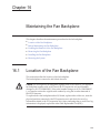
16.1
Location of the Fan Backplane
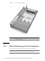
16.2
Before Maintaining the Fan Backplane
16.3
16.4
16.5
16.6
16.2.1
Types of maintenance
16.2.2
Maintenance flow
239
241
241
16.3.1
Active/cold maintenance
16.3.2
Inactive/cold maintenance
16.3.3
System stopped/cold maintenance
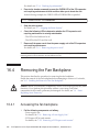
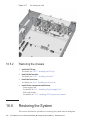
Removing the Fan Backplane
242
243
16.4.1
Accessing the fan backplane
244
16.4.2
Removing the fan backplane
245
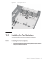
Installing the Fan Backplane
Installing the fan backplane
16.5.2
Restoring the chassis
247
250
250
16.6.1
Active/cold maintenance
16.6.2
Inactive/cold maintenance
16.6.3
System stopped/cold maintenance
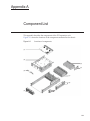
Component List
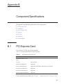
Appendix B
Component Specifications
B.1
PCI Express Card
B.2
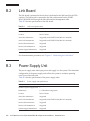
Link Board
B.3
Power Supply Unit
B.4
Fan Unit
257
B.5
PCI Tray
257
B.6
I/O Board
B.7
Fan Backplane
251
251
252
253
255
255
256
256
258
258
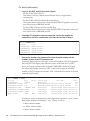
Updating the Firmware of the PCI Expansion Unit
Before Updating the Firmware
C.1.1
243
247
16.5.1
Restoring the System
242
244
Appendix A
C.1
240
Enabling the Removal of the Fan Backplane
Appendix C
xii
239
Precautions for updating
261
261
PCI Expansion Unit for Fujitsu M10/SPARC M10 Systems Service Manual ・ December 2014
261
C.1.2
How to check the serial number and firmware version of the
PCI expansion unit
C.2
C.3
Index
262
C.1.3
Time required for updating
C.1.4
Flow of update process
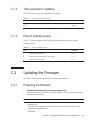
Updating the Firmware
265
265
265
C.2.1
Preparing the firmware
265
C.2.2
Importing the firmware into the system
C.2.3
Updating the firmware
266
267
Problems during Firmware Update
268
269
Contents
xiii
xiv PCI Expansion Unit for Fujitsu M10/SPARC M10 Systems Service Manual ・ December 2014
Preface
This document describes the maintenance procedure for the PCI expansion unit for
Oracle or Fujitsu M10/SPARC M10 Systems. The maintenance work should be
performed by service engineers and/or field engineers.
Fujitsu M10 is sold as SPARC M10 Systems by Fujitsu in Japan.
Fujitsu M10 and SPARC M10 Systems are identical products.
The preface includes the following sections:
Audience
■
■
Related Documentation
■
Text Conventions
■
Notes on Safety
■
Syntax of the Command-Line Interface (CLI)
■
Document Feedback
Audience
This document is intended for service engineers and field engineers who perform
maintenance work on the system.
xv
Related Documentation
All documents for your server are available online at the following locations.
Sun Oracle software-related documents (Oracle Solaris, etc.)
http://www.oracle.com/documentation/
■
■
Fujitsu documents
Japanese site
http://jp.fujitsu.com/platform/server/sparc/manual/
Global site
http://www.fujitsu.com/global/services/computing/server/sparc/downloads/manual/
The following table lists documents related to SPARC M10 Systems.
SPARC M10 Systems related documentation (*1)
Fujitsu M10/SPARC M10 Systems Getting Started Guide (*2)
Fujitsu M10/SPARC M10 Systems Quick Guide
Fujitsu M10/SPARC M10 Systems Important Legal and Safety Information (*2)
Software License Conditions for Fujitsu M10/SPARC M10 Systems
Fujitsu M10/SPARC M10 Systems Safety and Compliance Guide
Fujitsu M10/SPARC M10 Systems Security Guide
Fujitsu M10/SPARC M10 Systems/SPARC Enterprise/PRIMEQUEST Common Installation Planning Manual
Fujitsu M10/SPARC M10 Systems Installation Guide
Fujitsu M10-1/SPARC M10-1 Service Manual
Fujitsu M10-4/Fujitsu M10-4S/SPARC M10-4/SPARC M10-4S Service Manual
Crossbar Box for Fujitsu M10/SPARC M10 Systems Service Manual
PCI Expansion Unit for Fujitsu M10/SPARC M10 Systems Service Manual
Fujitsu M10/SPARC M10 Systems PCI Card Installation Guide
Fujitsu M10/SPARC M10 Systems System Operation and Administration Guide
Fujitsu M10/SPARC M10 Systems Domain Configuration Guide
Fujitsu M10/SPARC M10 Systems XSCF Reference Manual
Fujitsu M10/SPARC M10 Systems RCIL User Guide (*3)
Fujitsu M10/SPARC M10 Systems XSCF MIB and Trap Lists
Fujitsu M10/SPARC M10 Systems Product Notes
Fujitsu M10/SPARC M10 Systems Glossary
*1 The listed manuals are subject to change without notice.
*2 The printed manual comes with the product.
*3 This document applies specifically to the FUJITSU M10 and FUJITSU ETERNUS storage system.
xvi PCI Expansion Unit for Fujitsu M10/SPARC M10 Systems Service Manual ・ December 2014
Text Conventions
This manual uses the following fonts and symbols to express specific types of
information.
Font/Symbol
Meaning
Example
AaBbCc123
What you type, when contrasted with on-screen
computer output. ~This font indicates an example
of command input.
XSCF> adduser jsmith
AaBbCc123
The names of commands, files, and directories;
on-screen computer output.
This font indicates an example of command input
in the frame.
XSCF> showuser -P
User Name:
jsmith
Privileges:
useradm
auditadm
Italic
Indicates the name of a reference manual.
See the Fujitsu M10/SPARC M10
Systems Installation Guide.
""
Indicates the names of chapters, sections, items,
buttons, or menus.
See "Chapter 2 Network Connection."
Command syntax in the text
While the XSCF commands have a section number of (8) or (1), it is omitted from the
text.
The Oracle Solaris commands have a section number such as (1M) in the text.
Each command has a section number in a command name to prompt users to refer to
it.
Notes on Safety
Read the following documents thoroughly before using or handling any SPARC M10
Systems.
■
Fujitsu M10/SPARC M10 Systems Important Legal and Safety Information
■
Fujitsu M10/SPARC M10 Systems Safety and Compliance Guide
Preface
xvii
Syntax of the Command-Line Interface
(CLI)
The command syntax is as follows:
A variable that requires the input of a value must be put in Italics.
■
■
■
An optional element must be enclosed in [].
A group of options for an optional keyword must be enclosed in [] and delimited
by |.
Document Feedback
If you have any comments or requests regarding this document, please take a
moment to share it with us by indicating the manual code, manual title, and page,
and stating your points specifically through the following websites:
■
Japanese site
http://jp.fujitsu.com/platform/server/sparc/manual/
■
Global site
http://www.fujitsu.com/global/services/computing/server/sparc/downloads/manual/
xviii PCI Expansion Unit for Fujitsu M10/SPARC M10 Systems Service Manual ・ December 2014
Chapter 1
Before Starting Maintenance Work
This chapter describes the safety precautions that must be observed before starting
any maintenance work, and provides important information that you should know.
Note the meanings of each of the following symbols and labels to ensure that the
work is done correctly.
■
Warning/Caution Indications
1.1
■
Labels/Tags
■
Safety Precautions
■
Notes Regarding Static Electricity
■
Other Precautions
■
Emergency Power Off
■
Important Information about the XCP Firmware
Warning/Caution Indications
This manual uses the following conventions to indicate warning and alert messages,
which are intended to prevent injury to the user and others as well as damage to
property.
Warning - "WARNING" indicates a potential hazard that could result in death or
serious personal injury if the user does not perform the procedure correctly.
Caution - "CAUTION" indicates a potential hazard that could result in minor or
moderate personal injury if the user does not perform the procedure correctly. This
also indicates that damage to the unit or other property may occur if the user does
not perform the procedure correctly.
1
1.2
Labels/Tags
This section describes the labels and tags attached to the chassis.
When performing maintenance, always observe the precautions on the standard
labels attached to the chassis.
Caution - Do not remove the labels or tags.
Note - The contents of the labels and tags described here may differ from those actually
attached to the chassis.
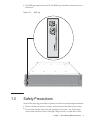
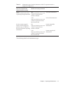
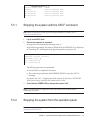
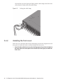
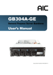
■
■
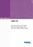
The system nameplate label (A in the figure) provides the product model number,
serial number, and version number required for maintenance and management.
The standard label (B in the figure) contains notes and the following approved
standards.
■
Security: NRTL/C
■
Electromagnetic wave: VCCI-A, FCC-A, DOC-A, KCC, and C-Tick
■
Security and electromagnetic wave: CE and GOST-R
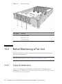
Figure 1-1
Positions of system nameplate label/standard label
A
B
2
PCI Expansion Unit for Fujitsu M10/SPARC M10 Systems Service Manual ・ December 2014
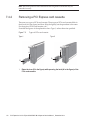
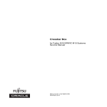
■
The RFID tag contains the Asset ID. The RFID tag is attached to the front cover of
the chassis.
Figure 1-2
1.3
RFID tag
Safety Precautions
Observe the following precautions to protect yourself when performing maintenance.
■
Observe all the precautions, warnings, and instructions described on the chassis.
■
Do not insert foreign objects into the openings in the chassis. Any such foreign
object could come into contact with high-voltage circuitry or could short circuit
Chapter 1
Before Starting Maintenance Work
3
the components, causing a fire or an electric shock.
■
Contact a service engineer and request inspection of the chassis.
Safety precautions on electricity
■
■
Wear a wrist strap when handling the I/O board, PCI tray, or other print boards.
■
Use a grounded power outlet.
■
1.4
Confirm that the voltage and frequency of your input power supply match those
shown on the electric rating label affixed on the chassis.
Do not make any mechanical or electrical alterations. We do not take any
responsibility for issues arising from non-authorized modifications to the chassis.
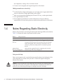
Notes Regarding Static Electricity
Observe the precautions concerning the electrostatic discharge (ESD) as described in
Table 1-1 to ensure the safety of personnel and the system.
Table 1-1
ESD precautions
Item
Note
Wrist strap
Wear an antistatic wrist strap when handling printed boards.
ESD mat
An approved ESD mat provides protection from static damage
when used together with a wrist strap. The mat also acts as a
cushion to protect the small parts that are attached to printed
boards.
Antistatic bag/
ESD safe packaging box
After removing a printed board or component, place it in the
antistatic bag or ESD safe packaging box.
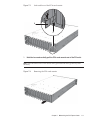
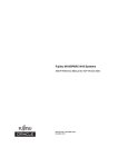
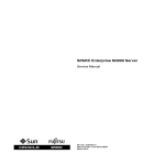
Using a wrist strap
Wear a wrist strap in such a way that the inner metal surface (A in the figure) of the
wrist strap band is in contact with your skin. Connect the clip (B in the figure)
directly to the chassis.
Caution - Do not connect the wrist strap clip to the ESD mat. By connecting the wrist
strap clip to the chassis, the operator and components assume the same electrical
potential, thus eliminating the danger of damage from static discharge.
4
PCI Expansion Unit for Fujitsu M10/SPARC M10 Systems Service Manual ・ December 2014
Figure 1-3
Wrist strap connection destination
A
B
1.5
Other Precautions
■
■
■
■
The printed boards of the PCI expansion unit are susceptible to static damage. To
prevent damage to the printed boards, therefore, wear a wrist strap and ground it
to the chassis prior to starting maintenance.
When mounting a component in the chassis, confirm that the connectors on the
chassis and components do not have any bent pins and that the pins are aligned. If
you attempt to mount a component while any of the connectors have bent pins,
the chassis or component may be damaged. When mounting a component,
perform the work carefully so as not to bend any pins.
If you cannot reach the latch lock of the connector when removing the management
cable or other cables, depress the latch with the tip of a flat-bladed screwdriver
and then remove the cable. If you attempt to remove the cable forcibly, the link
board and/or the PCI Express (PCIe) card may be damaged.
Do not use a power cord other than the specified type.
Chapter 1
Before Starting Maintenance Work
5
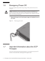
1.6
Emergency Power Off
This section explains the procedure for powering off the system in the case of an
emergency.
Caution - Immediately shut down the product in the event of an emergency (for
example, when the chassis emits smoke or flame) and then disconnect the input
power. Prevention of fire must always be your highest priority, regardless of the task
that you are currently performing.
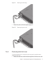
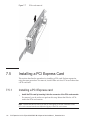
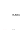
1.
Remove all the power cords from the power supply unit installed at the rear of
the chassis.
Figure 1-4
1.7
Removing power cords
Important Information about the XCP
Firmware
This section describes important information that you should know about the XCP
firmware version and when connecting the PCI expansion unit.
6
PCI Expansion Unit for Fujitsu M10/SPARC M10 Systems Service Manual ・ December 2014
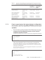
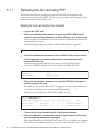
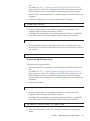
1.7.1
Precautions for updating the XCP firmware
■
[SPARC M10-1]
The logical domain configuration of the physical partition will return to the
factory default at the next startup when any of the following conditions are met: If
the logical domain configuration contains a guest domain, the OpenBoot PROM
environment variable of the control domain will also be initialized.
- When an update is performed from firmware version XCP2043 or earlier to
firmware version XCP2044 or later in a configuration with a PCI expansion unit
connected
- When a PCI expansion unit is installed or removed from a system with a
firmware version that is XCP2044 or later
Save the logical domain configuration information from Oracle Solaris to XML in
advance. To save it to XML, execute the ldm list-constraints -x command, and to
restore it from XML, execute the ldm init-system -i command. Also, save the
setting information for the OpenBoot PROM environment variable of the control
domain to the notepad, and then reset it. To display it, execute the printenv
command while the ok prompt is displayed. For details on these procedures, see
"1.7.3 How to save/restore the logical domain configuration information and the
OpenBoot PROM environment variable."
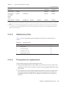
The processes to be performed when it is necessary to save/restore each item of
information related to the PCI expansion unit configuration are as follows.
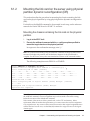
Table 1-2
1.7.2
Necessary processes related to the PCI expansion unit configuration
PCI expansion unit
installation
Domain configuration
Reconfiguration of
Oracle VM Server for
SPARC config
Resetting of OpenBoot
PROM environment
variable
Unsupported
factory-default
Unnecessary
Unnecessary
Unsupported
Contains a guest domain
Unnecessary
Unnecessary
Supported
factory-default
Unnecessary
Unnecessary
Supported
Contains a guest domain
Necessary (XML)
Necessary
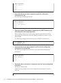
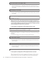
Notes on using the direct I/O function
■
[SPARC M10-4/M10-4S]
If the firmware version XCP2044 or later is used on the SPARC M10-4 or a
firmware version XCP2050 or later is used on the SPARC M10-4S and one of the
following operations is performed with the setpciboxdio command, the logical
domain configuration of the physical partition will return to the factory default at
the next startup. If the domain configuration contains a guest domain, the
OpenBoot PROM environment variable of the control domain will also be initialized.
- Changing the enable/disable setting for the direct I/O function of the PCI
Chapter 1
Before Starting Maintenance Work
7
expansion unit
- Installing/removing/replacing the PCI expansion unit for the PCIe slot of the
SPARC M10 chassis for which the direct I/O function of the PCI expansion unit
is enabled
Save the logical domain configuration information from Oracle Solaris to XML in
advance. To save it to XML, execute the ldm list-constraints -x command, and to
restore it from XML, execute the ldm init-system -i command. Also, save the
setting information for the OpenBoot PROM environment variable of the control
domain to the notepad, and then reset it. To display it, execute the printenv
command while the ok prompt is displayed. For details on these procedures, see
"1.7.3 How to save/restore the logical domain configuration information and the
OpenBoot PROM environment variable."
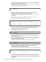
When executing the setpciboxdio command to change the enable/disable setting
for the direct I/O function of the PCI expansion unit, the following operations
must be performed to save/restore each item of information.
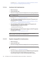
Table 1-3
Operations to change the enable/disable setting with the setpciboxdio command
PCI expansion unit
configuration
Domain configuration
Reconfiguration of
Oracle VM Server for
SPARC config
Resetting of OpenBoot
PROM environment
variable
Existence/nonexistence
factory-default
Unnecessary
Necessary
Existence/nonexistence
Contains a guest domain
Necessary (XML)
Necessary
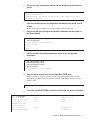
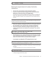
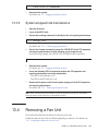
Suppose that the setpciboxdio command is executed to install, remove, or replace
the PCI expansion unit for the PCIe slot of the SPARC M10 chassis for which the
direct I/O function of the PCI expansion unit is enabled. The following operations
must be performed to save/restore each item of information:
Note - If you use the PCI Hot Plug (PHP) function to perform maintenance on the PCI
expansion unit, the direct I/O function is disabled. Therefore, it is not necessary to
save/restore each item of information.
8
PCI Expansion Unit for Fujitsu M10/SPARC M10 Systems Service Manual ・ December 2014
Table 1-4
Maintenance environment
Domain configuration
Reconfiguration of
Oracle VM Server
for SPARC config
Resetting of
OpenBoot PROM
environment
variable
When stopping PPAR for
installation/removal
factory-default
Contains a guest
domain
Unnecessary
Necessary (XML)
Unnecessary
Necessary
When stopping PPAR to
replace the failed PCI
expansion unit (*1)
factory-default
Contains a guest
domain
Unnecessary
Necessary (XML)
Unnecessary
Necessary
When stopping PPAR to
replace the normal PCI
expansion unit (*1)
factory-default
Contains a guest
domain
Unnecessary
Unnecessary
Unnecessary
Unnecessary
*1:
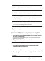
1.7.3
Operations when installing/removing/replacing the PCI expansion unit for the
PCIe slot of the SPARC M10 chassis for which the direct I/O function is enabled
This includes the replacement of the link card, link cable, management cable or link board.
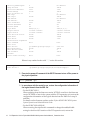
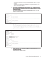
How to save/restore the logical domain configuration
information and the OpenBoot PROM environment
variable
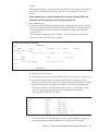
1.
Execute the ldm ls-spconfig command on Oracle Solaris super-user prompt
to display the list of the configuration information, and then confirm the
configuration information to be saved.
The following example shows that test3 is the current configuration information.
# ldm ls-spconfig
factory-default
test1
test2
test3 [current]
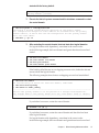
If the current configuration is shown as "next poweron," execute the ldm
add-spconfig command to save the current configuration information. This is
because the configuration information stored in the XSCF is different from that
stored in the control domain.
In the following example, the current configuration information is saved in test4
because test3 is "next poweron."
# ldm ls-spconfig
factory-default
test1
test2
test3 [next poweron]
# ldm add-spconfig test4
Chapter 1
Before Starting Maintenance Work
9
# ldm ls-spconfig
factory-default
test1
test2
test3
test4 [current]
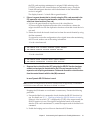
2.
Execute the ldm set-spconfig command to specify the configuration
information to be set.
The following example specifies test1.
# ldm set-spconfig test1
# ldm ls-spconfig
factory-default
test1 [next poweron]
test2
test3
3.
Execute the poweroff and poweron commands of the XSCF firmware to turn
off/on the power to the physical partition.
Before turning off the power to the system, stop the logical domain with an
appropriate procedure and use the ldm unbind command to transfer it to the
inactive state.
The following example shows that the power to PPAR 0 is turned off/on.
XSCF> poweroff -p 0
XSCF> poweron -p 0
4.
Execute the ldm ls-spconfig command to confirm that the configuration
information is set as specified.
The following example shows that test1 is set as the current configuration
information.
# ldm ls-spconfig
factory-default
test1 [current]
test2
test3
5.
Execute the ldm ls-constraints -x command to save the current configuration
information.
If necessary, backup XML.
In the following example, the current configuration information is saved in
test1.xml.
# ldm ls-constraints -x > /var/tmp/test1.xml
10
PCI Expansion Unit for Fujitsu M10/SPARC M10 Systems Service Manual ・ December 2014
6.
Execute the more command to confirm that the configuration information is
correct.
# more /var/tmp/test1.xml
<?xml version="1.0"?>
<LDM_interface version="1.3" xmlns:xsi=http://www.w3.org/2001/
XMLSchema-instancce
7.
If there are multiple pieces of configuration information to be saved, save all
of them.
Repeat from step 2 to step 6 to save the configuration information.
8.
Execute the ldm set-spconfig factory-default command to set the system to
the factory default.
# ldm set-spconfig factory-default
# ldm ls-spconfig
factory-default [next poweron]
test1 [current]
test2
test3
9.
Execute the ldm rm-spconfig command to delete all the configuration
information.
# ldm rm-spconfig test1
# ldm rm-spconfig test2
# ldm rm-spconfig test3
# ldm ls-config
factory-default [next poweron]
10. Stop the logical domain to set it to the OpenBoot PROM state.
Before turning off the power to the system, stop the logical domain with an
appropriate procedure and use the ldm unbind command to transfer it to the
inactive state.
# shutdown -i0 -g0 -y
11. Check the OpenBoot PROM environment variable with the printenv command.
{0} ok printenv
Variable Name
ttya-rts-dtr-off
ttya-ignore-cd
keyboard-layout
reboot-command
security-mode
security-password
Value
false
true
Default Value
false
true
none
No default
No default
Chapter 1
Before Starting Maintenance Work
11
security-#badlogins
diag-switch?
local-mac-address?
fcode-debug?
scsi-initiator-id
oem-logo
oem-logo?
oem-banner
oem-banner?
ansi-terminal?
screen-#columns
screen-#rows
ttya-mode
output-device
input-device
auto-boot-on-error?
load-base
auto-boot?
network-boot-arguments
boot-command
boot-file
boot-device
multipath-boot?
boot-device-index
use-nvramrc?
nvramrc
error-reset-recovery
0
false
true
false
7
false
true
80
34
9600,8,n,1,virtual-console
virtual-console
false
16384
false
No default
false
true
false
7
No default
false
No default
false
true
80
34
9600,8,n,1,virtual-console
virtual-console
false
16384
true
boot
boot
/pci@8000/pci@4/pci@0/pc ...
false
0
false
disk net
false
0
false
boot
boot
false
If there is any omitted section with "...," review this section.
{0} ok printenv boot-device
boot-device =
/pci@8000/pci@4/pci@0/pci@0/scsi@0/disk@p0,0
12. Execute the poweroff command of the XSCF firmware to turn off the power to
the physical partition.
XSCF> poweroff -p 0
13. In accordance with the model in use, restore the configuration information of
the logical domain from the XML file.
- For the SPARC M10-1
When updating from the firmware version XCP2043 or earlier to the firmware
version XCP2044 or later in the system with the PCI expansion unit, restore the
configuration information of the logical domain from the XML file in step 14
and later.
For details on the firmware update, see the Fujitsu M10/SPARC M10 Systems
System Operation and Administration Guide.
- For the SPARC M10-4/M10-4S
When executing the setpciboxdio command to change the enable/disable
setting for the direct I/O function of the PCI expansion unit, restore the
12
PCI Expansion Unit for Fujitsu M10/SPARC M10 Systems Service Manual ・ December 2014
configuration information of the logical domain from the XML file in step 14
and later.
For details on the setpciboxdio command, see the Fujitsu M10/SPARC M10
Systems XSCF Reference Manual.
14. Execute the showdomainconfig command of the XSCF firmware to confirm
that the configuration information at the next startup of the physical partition
is the factory default.
The following example shows that the configuration information at the next
startup is the factory default.
XSCF> showdomainconfig -p 0
PPAR-ID
:0
Booting config
(Current) :factory-default
(Next)
:factory-default
----------------------------------------------------------------------------Index
:1
config_name :factory-default
domains
:1
date_created:-
The following example shows that the configuration information at the next
startup is not the factory default. In this case, execute the setdomainconfig
command to set the configuration information at the next startup of the physical
partition to the factory default.
XSCF> showdomainconfig -p 0
PPAR-ID
:0
Booting config
(Current) :test1
(Next)
:test2
:
XSCF> setdomainconfig -p 0 -i 1
XSCF> showdomainconfig -p 0
PPAR-ID
:0
Booting config
(Current) :test1
(Next)
: factory-default
----------------------------------------------------------------------------Index
:1
config_name :factory-default
domains
:1
date_created:-
15. Check auto-boot? of the OpenBoot PROM environment variable to stop in the
OpenBoot PROM state.
If the value is true, change it to false.
Chapter 1
Before Starting Maintenance Work
13
XSCF> setpparparam -p 0 -s bootscript "setenv auto-boot? false"
PPAR-ID of PPARs that will be affected:0
OpenBoot PROM variable bootscript will be changed.
Continue? [y|n] :y
If you changed the value, check the OpenBoot PROM environment variable.
XSCF> showpparparam -p 0
use-nvramrc
:security-mode
:bootscript
:
setenv auto-boot? false
16. Execute the poweron command to restart the physical partition.
XSCF> poweron -p 0
17. Execute the showdomainstatus command to check the status of the control
domain.
Confirm that the status of the control domain is displayed as "OpenBoot
Running" indicating that it is in the OpenBoot PROM state.
XSCF> showdomainstatus -p 0
Logical Domain Name
Status
primary
OpenBoot Running
18. Execute the console command to switch to the control domain console.
XSCF> console -p 0 -y
Console contents may be logged.
Connect to PPAR-ID 0?[y|n] :y
19. Based on the record in step 11, restore the OpenBoot PROM environment
variable.
In the following example, auto-boot? is restored to true.
{0} ok setenv auto-boot? true
auto-boot? =
true
{0} ok printenv auto-boot?
auto-boot? =
true
20. Boot Oracle Solaris.
{0} ok boot
21. With the Oracle Solaris super-user prompt, confirm that the system has
14
PCI Expansion Unit for Fujitsu M10/SPARC M10 Systems Service Manual ・ December 2014
started with the factory default.
# ldm ls-spconfig
factory-default [current]
22. Execute the ldm init-system command and the shutdown command to restart
the control domain.
# ldm init-system -i /var/tmp/test1.xml
Initiating a delayed reconfiguration operation on the primary domain.
All configuration changes for other domains are disabled until the primary
domain reboots, at which time the new configuration for the primary domain
will also take effect.
# shutdown -y -g0 -i6
23. After restarting the control domain, bind and start other logical domains.
For logical domains with dependency, start them in the correct order.
In the following example, both root-domain and guest-domain are bound and
started.
#
#
#
#
ldm
ldm
ldm
ldm
bind root-domain
start-domain root-domain
bind guest-domain
start-domain guest-domain
If the binding failed because an overlapping resource exists, delete the relevant
resource from the logical domain.
The following example shows that an overlapping resource has been deleted.
# ldm bind root-domain
No free matching I/O device for LDom root-domain, name PCIE1
# ldm start-reconf primary
# ldm remove-io PCIE1 primary
-----------------------------------------------------------------------------Notice: The primary domain is in the process of a delayed reconfiguration.
Any changes made to the primary domain will only take effect after it reboots.
------------------------------------------------------------------------------
If you deleted a resource, restart the control domain.
# shutdown -i6 -g0 -y
If you deleted a resource, restart the control domain and then bind and start
other logical domains.
For logical domains with dependency, start them in the correct order.
In the following example, both root-domain and guest-domain are bound and
Chapter 1
Before Starting Maintenance Work
15
started.
#
#
#
#
ldm
ldm
ldm
ldm
bind root-domain
start-domain root-domain
bind guest-domain
start-domain guest-domain
24. Execute the ldm ls command to confirm that the logical domain is operating
normally.
# ldm ls
NAME
primary
root-domain
:
:
STATE
active
active
FLAGS
-n-cv-t----
CONS
UART
5000
VCPU
8
8
MEMORY
8G
4G
UTIL
66%
19%
UPTIME
4m
29s
25. After restoring the configuration information, execute the ldm add-spconfig
command to save the configuration information to the XSCF.
In the following example, the configuration information of test1 has been saved
to the XSCF.
# ldm add-spconfig test1
# ldm ls-spconfig
factory-default
test1 [current]
26. If there are multiple pieces of configuration information to be restored,
restore all of them.
Repeat from step 14 to step 25 to restore the configuration information.
16
PCI Expansion Unit for Fujitsu M10/SPARC M10 Systems Service Manual ・ December 2014
Chapter 2
Understanding the PCI Expansion Unit
Components
This chapter describes the components of the PCI expansion unit.
Before starting any maintenance work, check and understand the configuration of
the components and the LED indications.
■
Identifying the Names and Locations of Components
■
Checking the Status with the LED
For the specifications of each component, see "Appendix B Component Specifications."
2.1
Identifying the Names and Locations of
Components
This section describes the names and locations of each component.
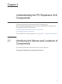
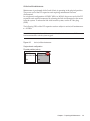
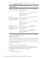
Components that can be accessed from the front
17
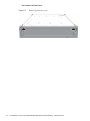
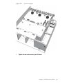
Figure 2-1
Location of components that can be accessed from the front
(1)
Location
number
Component
1
Fan unit
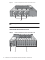
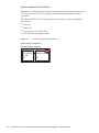
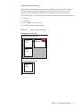
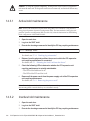
Components that can be accessed from the rear
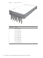
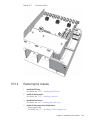
Figure 2-2
(1)
18
Location of components that can be accessed from the rear
(2)
(3)
PCI Expansion Unit for Fujitsu M10/SPARC M10 Systems Service Manual ・ December 2014
Location
number
Component
1
Power supply unit
2
Link board (*)
3
PCI Express (PCIe) card
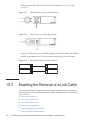
*: The link board can be mounted only in its dedicated slot.
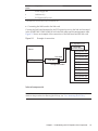
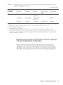
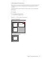
■
Connecting the link board to the link card
Connect the link board mounted in the PCI expansion unit to the link card mounted
in the SPARC M10-1/M10-4/M10-4S with the link cables and the management cable.
Figure 2-3 shows an example of the connection of the link board and the link card.
Figure 2-3
Example of connection
PCI expansion unit
Link board
(Mounted as standard)
PCI Express slot
Server
PCI Express slot
Link cable
PCI Express slot
Link card
PCI Express slot
PCI Express slot
PCI Express slot
Management cable
PCI Express slot
PCI Express slot
PCI Express slot
PCI Express slot
PCI Express slot
PCI Express slot
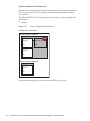
Internal components
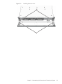
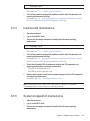
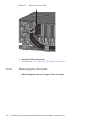
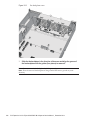
Note - To access internal components, remove the PCI tray from the PCI expansion unit. For
details on the procedure for removing the PCI tray, see "14.4 Removing the PCI Tray."
Chapter 2 Understanding the PCI Expansion Unit Components
19
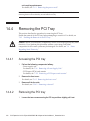
Figure 2-4
Locations of internal components
(2)
(1)
(3)
(4)
2.2
Location
number
Component
1
PCI tray
2
I/O board
3
PSU backplane
4
Fan backplane
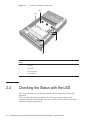
Checking the Status with the LED
This section describes how to identify the state of each component from its LED
indication.
LEDs are mounted on the front panel of the PCI expansion unit and on each
component that can be maintained. If an error occurs, check the LEDs to see which
component requires maintenance.
20
PCI Expansion Unit for Fujitsu M10/SPARC M10 Systems Service Manual ・ December 2014
2.2.1
Front LEDs on the PCI expansion unit
The following LEDs are mounted on the front panel of the PCI expansion unit to
indicate the status.
■
Fan unit (A in the figure)
■
PCI expansion unit (B in the figure)
Figure 2-5
LEDs on front of the chassis
A
B
The LEDs on each component and the statuses those LEDs indicate are listed below.
Table 2-1
Name
CHECK
LEDs and status of fan unit
Color
Status
Description
Amber
On
Indicates that an error has occurred.
Blinking (*)
Indicates that the component requires maintenance.
(This function is also referred to as the "locator.")
Off
Indicates the normal state. Or, the breaker is open
or the power supply is otherwise off.
*: The blink interval is 1 second (1 Hz).
Chapter 2 Understanding the PCI Expansion Unit Components
21
Table 2-2
LEDs and status of PCI expansion unit
Name
READY
CHECK
Color
Status
Description
Green
On
Indicates that the component is operating.
Blinking (*)
Power is supplied, but the system is not running.
During this time, all of the I/O boards will be in
the standby state.
Off
The system is stopped.
On
Indicates that an error has occurred.
Blinking (*)
Indicates that the PCI expansion unit chassis
requires maintenance. (This function is also
referred to as the "locator.")
Off
Indicates the normal state. Or, the breaker is open
or the power supply is otherwise off.
Amber
*: The blink interval is 1 second (1 Hz).
2.2.2
LEDs on rear of PCI expansion unit
An LED is mounted on each component. If a component experiences an error, check
the LEDs to see which component requires maintenance. Check the LEDs before
starting maintenance work.
The following LEDs are mounted on the rear panel of the PCI expansion unit.
■
Power supply unit (A in the figure)
■
I/O board (B in the figure)
■
Link board (C in the figure)
■
PCIe slot (D in the figure)
Figure 2-6
A
LEDs on the rear of the chassis
B
C
D
The LEDs mounted on each component and the statuses indicated by those LEDs are
listed below.
22
PCI Expansion Unit for Fujitsu M10/SPARC M10 Systems Service Manual ・ December 2014
Table 2-3
LEDs and status of power supply unit
Name
POWER/FAIL
Color
Status
Description
Green
On
The input power is turned on and power is being
supplied normally.
Blinking (*)
Standby condition.
On
Indicates that an error has occurred.
Blinking (*)
Warning state (an error has occurred but the
power unit is still operating).
Off
The input power is turned off.
Amber
*: The blink interval is 1 second (1 Hz).
Table 2-4
LEDs and status of I/O board
Name
Color
Status
Description
CHECK
(Indicator)
Amber
On
Indicates that an error has occurred.
Blinking (*)
Indicates that the component requires maintenance.
(This function is also referred to as the "locator.")
Off
Indicates the normal state. Or, the breaker is open
or the power supply is otherwise off.
*: The blink interval is 1 second (1 Hz).
Table 2-5
LEDs and status of link board
Name
Color
Status
Description
LINK STATUS
(PCI-Ex)
/left side
Green
On
The link is established with PCI-Express Gen3 x8.
Blinking (*)
The link is established with other than PCIExpress Gen3 x8 (degradation condition).
Off
The link is down.
On
The management link is established.
Blinking (*)
The management link is disconnected.
Off
Indicates that power is not being supplied.
LINK STATUS
(Management)
/right side
Green
*: The blink interval is 1 second (1 Hz).
Chapter 2 Understanding the PCI Expansion Unit Components
23
Table 2-6
Name
POWER
ATTENTION
LEDs and status of PCIe slot
Color
Status
Description
Green
On
Indicates that power is being supplied.
Off
Indicates that power is not being supplied.
On
Indicates that an error has occurred.
Blinking (*)
Indicates that the component requires maintenance.
(This function is also referred to as the "locator.")
Off
Indicates the normal state.
Amber
*: The blink interval is 1 second (1 Hz).
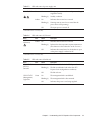
2.2.3
LEDs on link card
The link card is mounted in the PCIe slot of the server.
24
PCI Expansion Unit for Fujitsu M10/SPARC M10 Systems Service Manual ・ December 2014
Figure 2-7
LEDs of link card
SPARC M10-1
(1)
(2)
SPARC M10-4/M10-4S
(1)
(2)
The LEDs on the link card and the statuses indicated by those LEDs are listed below.
Chapter 2 Understanding the PCI Expansion Unit Components
25
Table 2-7
LEDs and status of link card
Location
number
Name
Color
Status
Description
1
LINK STATUS
(PCI-Ex)
Green
On
The link is established with PCI-Express
Gen3 x8.
Blinking (*)
The link is established with other than
PCI-Express Gen3 x8 (degradation
condition).
Off
The link is down.
On
The management link is established.
Blinking (*)
The management link is disconnected.
Off
Indicates that power is not being
supplied.
2
LINK STATUS
(Management)
Green
*: The blink interval is 1 second (1 Hz).
26
PCI Expansion Unit for Fujitsu M10/SPARC M10 Systems Service Manual ・ December 2014
Chapter 3
Troubleshooting
This chapter describes how to determine and confirm the cause if an error occurs.
■
Suspected Failure Conditions
3.1
■
Determining the Causes of Individual Failures
■
Identifying a Failure
■
Locating the PCI Expansion Unit Requiring Maintenance
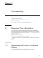
Suspected Failure Conditions
This section explains suspected failure conditions. Use the flow to determine the
cause of a failure and identify the failure location in the following cases. For details
on the flow for determining the cause of a failure, see "3.2 Determining the Causes
of Individual Failures."
■
When the CHECK LED is on
■
■
■
3.2
When an error message is displayed on the console
When an error is displayed as a result of executing a command for checking the
status
When an error is displayed in the error log
Determining the Causes of Individual
Failures
This section explains the flow for determining the causes of failures.
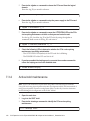
27
Figure 3-1
Troubleshooting flow
Start
Is the LED on the power
supply unit off?
YES
Check the connection of the power
supply unit and power cords.
NO
Was e-mail sent by the
XSCF mail function?
YES
NO
Confirm that an error message is
displayed on the OS and XSCF
consoles.
Execute showlogs on XSCF to
display failure information.
Check /var/adm/messages on
Oracle Solaris.
Write down the displayed failure
information.
Contact our service engineer.
End
3.3
Identifying a Failure
This section explains the method for identifying a failure. Use the flow described in
"3.2 Determining the Causes of Individual Failures" to determine the appropriate
way of checking for a failure.
28
PCI Expansion Unit for Fujitsu M10/SPARC M10 Systems Service Manual ・ December 2014
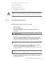
3.3.1
Checking the LED indications
Identify the component requiring maintenance by checking the LEDs on both the
front and rear panels of the PCI expansion unit, and the LEDs on the link card of the
server to which the PCI expansion unit is connected. To maintain a component,
determine its status from the LEDs and then start the maintenance work.
■
LEDs on front of PCI expansion unit
The status of the PCI expansion unit or fan unit can be determined by checking the
LED or CHECK LED on the respective devices. For details, see "2.2.1 Front LEDs
on the PCI expansion unit."
■
■
3.3.2
LEDs on rear of PCI expansion unit
By checking the LEDs mounted on the components that can be maintained, the
status of each component or the error location can be determined. For details, see
"2.2.2 LEDs on rear of PCI expansion unit."
LEDs on link card
Check the LED on the link card of the server to which the PCI expansion unit is
connected. For details, see "2.2.3 LEDs on link card."
Checking error messages
Display the error messages to check the log information and obtain an error overview.
You can use either of the following two methods to check the error messages:
■
Checking the error log information with the XSCF shell
For details, see "12.1 Checking a Log Saved by the XSCF" in the Fujitsu
M10/SPARC M10 Systems System Operation and Administration Guide.
■
3.3.3
Checking messages with Oracle Solaris
For details, see "12.2 Checking Warning and Notification Messages" in the
Fujitsu M10/SPARC M10 Systems System Operation and Administration Guide.
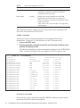
Checking the status
Execute the command to check the status of the PCI expansion unit, PCI Express
(PCIe) card, or the system.
Table 3-1 lists the commands for checking the status.
Table 3-1
Status check command
Type
Command
Description
XSCF
ioxadm
Displays information on the PCI expansion unit. The
system administrator and service engineer can manage
the PCI expansion unit by executing the ioxadm
command.
Chapter 3
Troubleshooting
29
Table 3-1
Status check command (continued)
Type
Command
Description
OpenBoot PROM
show-devs
Displays device tree information on the PCIe card and
other devices connected to the host. Execute this
command from the ok prompt.
Oracle Solaris
prtdiag
Displays the system configuration and all Field
Replaceable Units (FRUs) that have experienced
failures. Execute this command from the Oracle Solaris
super-user prompt.
"FRU" refers to any component that can be replaced by
a field engineer.
The command execution examples shown here are based on the assumption that
PCIe cards are inserted into all of the slots.
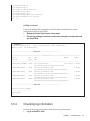
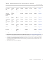
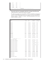
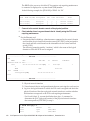
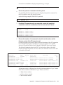
ioxadm command
Execute the ioxadm command to determine the environmental conditions
(temperature, voltage, etc.) or LED indications of the PCI expansion unit.
1. Log in to the XSCF shell.
2.
Execute the ioxadm command to check the environmental conditions of the
specified PCI expansion unit.
The following example shows the environmental conditions for the PCIBOX#2008
"2008" is the last four digits of the serial number of the PCI expansion unit.
XSCF> ioxadm env -te PCIBOX#2008
Location
Sensor
PCIBOX#2008
AIRFLOW
PCIBOX#2008
P_CONSUMPTION
PCIBOX#2008/PSU#0
FAN
PCIBOX#2008/PSU#1
FAN
PCIBOX#2008/FAN#0
FAN
PCIBOX#2008/FAN#1
FAN
PCIBOX#2008/FAN#2
FAN
PCIBOX#2008/IOB
T_INTAKE
PCIBOX#2008/IOB
T_PART_NO0
PCIBOX#2008/IOB
T_PART_NO1
PCIBOX#2008/IOB
T_PART_NO2
PCIBOX#2008/IOB
V_12_0V
PCIBOX#2008/IOB
V_3_3_NO0
PCIBOX#2008/IOB
V_3_3_NO1
PCIBOX#2008/IOB
V_3_3_NO2
PCIBOX#2008/IOB
V_3_3_NO3
PCIBOX#2008/IOB
V_1_8V
PCIBOX#2008/IOB
V_0_9V
Value Resolution Units
180.000
0.000 CHM
68.000
0.000 W
3936.000
0.000 RPM
3584.000
0.000 RPM
3374.000
0.000 RPM
3374.000
0.000 RPM
3374.000
0.000 RPM
26.000
0.000 C
31.500
0.000 C
30.750
0.000 C
31.500
0.000 C
12.069
0.000 V
3.293
0.000 V
3.295
0.000 V
3.291
0.000 V
3.300
0.000 V
1.804
0.000 V
0.900
0.000 V
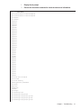
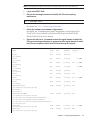
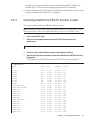
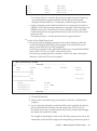
show-devs command
Execute the show-devs command of OpenBoot PROM to display the path from the
host server to the PCIe card on the I/O board.
30
PCI Expansion Unit for Fujitsu M10/SPARC M10 Systems Service Manual ・ December 2014
1.
Display the ok prompt.
2.
Execute the show-devs command to check the device tree information.
{0} ok show-devs
/pci-performance-counters@8100
/pci-performance-counters@8000
/pci@8100
/pci@8000
/cpu@1f
/cpu@1e
/cpu@1d
/cpu@1c
/cpu@1b
/cpu@1a
/cpu@19
/cpu@18
/cpu@17
/cpu@16
/cpu@15
/cpu@14
/cpu@13
/cpu@12
/cpu@11
/cpu@10
/cpu@f
/cpu@e
/cpu@d
/cpu@c
/cpu@b
/cpu@a
/cpu@9
/cpu@8
/cpu@7
/cpu@6
/cpu@5
/cpu@4
/cpu@3
/cpu@2
/cpu@1
/cpu@0
/virtual-devices@100
/iscsi-hba
/virtual-memory
/memory@m7e00,60000000
/aliases
/options
/openprom
/chosen
/packages
/pci@8100/pci@4
/pci@8100/pci@4/pci@0
/pci@8100/pci@4/pci@0/pci@9
/pci@8100/pci@4/pci@0/pci@1
/pci@8100/pci@4/pci@0/pci@0
Chapter 3
Troubleshooting
31
/pci@8100/pci@4/pci@0/pci@0/network@0,1
/pci@8100/pci@4/pci@0/pci@0/network@0
/pci@8000/pci@4
/pci@8000/pci@4/pci@0
/pci@8000/pci@4/pci@0/pci@8
/pci@8000/pci@4/pci@0/pci@2
/pci@8000/pci@4/pci@0/pci@1
/pci@8000/pci@4/pci@0/pci@0
/pci@8000/pci@4/pci@0/pci@8/pci@0
/pci@8000/pci@4/pci@0/pci@8/pci@0/pci@0
/pci@8000/pci@4/pci@0/pci@8/pci@0/pci@0/pci@0
/pci@8000/pci@4/pci@0/pci@8/pci@0/pci@0/pci@0/pci@1
/pci@8000/pci@4/pci@0/pci@8/pci@0/pci@0/pci@0/pci@1/pci@0
/pci@8000/pci@4/pci@0/pci@8/pci@0/pci@0/pci@0/pci@1/pci@0/pci@11
/pci@8000/pci@4/pci@0/pci@8/pci@0/pci@0/pci@0/pci@1/pci@0/pci@10
/pci@8000/pci@4/pci@0/pci@8/pci@0/pci@0/pci@0/pci@1/pci@0/pci@8
/pci@8000/pci@4/pci@0/pci@8/pci@0/pci@0/pci@0/pci@1/pci@0/pci@1
/pci@8000/pci@4/pci@0/pci@8/pci@0/pci@0/pci@0/pci@1/pci@0/pci@0
/pci@8000/pci@4/pci@0/pci@8/pci@0/pci@0/pci@0/pci@1/pci@0/pci@11/pci@0
/pci@8000/pci@4/pci@0/pci@8/pci@0/pci@0/pci@0/pci@1/pci@0/pci@11/pci@0/pci@11
/pci@8000/pci@4/pci@0/pci@8/pci@0/pci@0/pci@0/pci@1/pci@0/pci@11/pci@0/pci@10
/pci@8000/pci@4/pci@0/pci@8/pci@0/pci@0/pci@0/pci@1/pci@0/pci@11/pci@0/pci@1
/pci@8000/pci@4/pci@0/pci@8/pci@0/pci@0/pci@0/pci@1/pci@0/pci@11/pci@0/pci@0
/pci@8000/pci@4/pci@0/pci@8/pci@0/pci@0/pci@0/pci@1/pci@0/pci@10/pci@0
/pci@8000/pci@4/pci@0/pci@8/pci@0/pci@0/pci@0/pci@1/pci@0/pci@10/pci@0/pci@11
/pci@8000/pci@4/pci@0/pci@8/pci@0/pci@0/pci@0/pci@1/pci@0/pci@10/pci@0/pci@10
/pci@8000/pci@4/pci@0/pci@8/pci@0/pci@0/pci@0/pci@1/pci@0/pci@10/pci@0/pci@1
/pci@8000/pci@4/pci@0/pci@8/pci@0/pci@0/pci@0/pci@1/pci@0/pci@10/pci@0/pci@0
/pci@8000/pci@4/pci@0/pci@8/pci@0/pci@0/pci@0/pci@1/pci@0/pci@10/pci@0/pci@1/
FJSV,eulsa@0
/pci@8000/pci@4/pci@0/pci@8/pci@0/pci@0/pci@0/pci@1/pci@0/pci@10/pci@0/pci@1/
FJSV,eulsa@0/tape
/pci@8000/pci@4/pci@0/pci@8/pci@0/pci@0/pci@0/pci@1/pci@0/pci@10/pci@0/pci@1/
FJSV,eulsa@0/disk
/pci@8000/pci@4/pci@0/pci@2/pci@0
/pci@8000/pci@4/pci@0/pci@2/pci@0/usb@4,1
/pci@8000/pci@4/pci@0/pci@2/pci@0/usb@4
/pci@8000/pci@4/pci@0/pci@1/network@0,1
/pci@8000/pci@4/pci@0/pci@1/network@0
/pci@8000/pci@4/pci@0/pci@0/scsi@0
/pci@8000/pci@4/pci@0/pci@0/scsi@0/disk
/pci@8000/pci@4/pci@0/pci@0/scsi@0/tape
/virtual-devices@100/channel-devices@200
/virtual-devices@100/flashprom@0
/virtual-devices@100/rtc@5
/virtual-devices@100/console@1
/virtual-devices@100/channel-devices@200/virtual-domain-service@0
/virtual-devices@100/channel-devices@200/virtual-channel@3
/virtual-devices@100/channel-devices@200/virtual-channel-client@2
/virtual-devices@100/channel-devices@200/virtual-channel-client@1
/virtual-devices@100/channel-devices@200/virtual-channel@0
/iscsi-hba/disk
/openprom/client-services
/packages/obp-tftp
/packages/kbd-translator
32
PCI Expansion Unit for Fujitsu M10/SPARC M10 Systems Service Manual ・ December 2014
/packages/SUNW,asr
/packages/dropins
/packages/terminal-emulator
/packages/disk-label
/packages/deblocker
/packages/SUNW,probe-error-handler
/packages/SUNW,builtin-drivers
{0} ok
prtdiag command
Execute the prtdiag(1M) command of Oracle Solaris to determine the system
configuration and any failed FRUs.
1. Display the Oracle Solaris super-user prompt.
2.
Execute the prtdiag(1) command to determine the system configuration and
any failed FRUs.
# prtdiag -v
System Configuration: Oracle Corporation
Memory size: 64000 Megabytes
sun4v SPARC M10-4
------------------------Omitted-----------------------================================ IO Devices ================================
Slot +
Bus
Name +
Model
Speed
Status
Type Path
---------------------------------------------------------------------------/BB0/CMUL/SASHBA PCIE scsi-pciex1000,87
LSI,2308_2 5.0GTx8
/pci@8000/pci@4/pci@0/pci@0/scsi@0
/BB0/CMUL/NET0
PCIE network-pciex14e4,1656
2.5GTx1
/pci@8000/pci@4/pci@0/pci@9/network@0
/BB0/CMUL/NET1
PCIE network-pciex14e4,1656
2.5GTx1
/pci@8000/pci@4/pci@0/pci@9/network@0,1
/BB0/CMUL/NET2
PCIE network-pciex14e4,1656
2.5GTx1
/pci@8000/pci@4/pci@0/pci@a/network@0
/BB0/CMUL/NET3
PCIE network-pciex14e4,1656
2.5GTx1
/pci@8000/pci@4/pci@0/pci@a/network@0,1
------------------------Omitted-----------------------Chassis Serial Number
--------------------2081203001
#
3.3.4
Checking log information
Execute the showlogs command to check the error log information.
1. Log in to the XSCF shell.
Chapter 3
Troubleshooting
33
2.
Execute the showlogs command to determine the error log information.
The log information is listed in the order of date, with the oldest appearing first.
The following example shows that an Alarm status occurred in PSU#1 and
PSU#2 at 12:45:31 on Oct 20, the Alarm status changed to a Warning status at
15:45:31 on the same day, and then the Alarm status further expanded to PSU#1,
PSU#2, and PSU#3 at 17:45:31 on the same day.
XSCF> showlogs error
Date: Oct 20 12:45:31 JST 2012
Code: 00112233-445566778899aabbcc-8899aabbcceeff0011223344
Status: Alarm
Occurred: Oct 20 12:45:31.000 JST 2012
FRU: PSU#1,PSU#2
Msg: ACFAIL occurred (ACS=3)(FEP type = A1)
Date: Oct 20 15:45:31 JST 2012
Code: 00112233-445566778899aabbcc-8899aabbcceeff0011223344
Status: Warning
Occurred: Oct 20 15:45:31.000 JST 2012
FRU: PSU#1,PSU#2
Msg: ACFAIL occurred (ACS=3)(FEP type = A1)
Date: Oct 20 17:45:31 JST 2012
Code: 00112233-445566778899aabbcc-8899aabbcceeff0011223344
Status: Alarm
Occurred: Oct 20 17:45:31.000 JST 2012
FRU: PSU#1,PSU#2, PSU#3,*
Msg: ACFAIL occurred (ACS=3)(FEP type = A1)
3.4
Locating the PCI Expansion Unit
Requiring Maintenance
This section describes the procedure for locating a PCI expansion unit requiring
maintenance by causing the CHECK LED (locator) on the front panel of the chassis to
blink.
Execute the ioxadm command of the XSCF firmware to cause the CHECK LED for
the PCI expansion unit requiring maintenance to blink to locate it. For details on the
location of the CHECK LED and the procedure for checking it, see "2.2.1 Front
LEDs on the PCI expansion unit."
1. Log in to the XSCF shell.
2.
Execute the ioxadm command to cause the CHECK LED of the PCI expansion
unit requiring maintenance to blink to locate it.
In the following example, the CHECK LED of PCIBOX#2008 is specified.
XSCF> ioxadm locator on PCIBOX#2008
Location Sensor Value Resolution Units
PCIBOX#2008 LOCATE Blink - LED
PCIBOX#2008/FAN#0 SERVICE Blink - LED
34
PCI Expansion Unit for Fujitsu M10/SPARC M10 Systems Service Manual ・ December 2014
Chapter 4
Preparing for Maintenance
This chapter describes the preparations that must be completed prior to performing
any maintenance, as well as the types of maintenance.
■
Preparing Tools Required for Maintenance
4.1
■
Understanding Types of Maintenance
■
Precautions for Maintenance
Preparing Tools Required for
Maintenance
This section explains the tools required for maintenance. Table 4-1 lists the tools
required for maintenance.
Table 4-1
4.2
Maintenance tools
Item
Use
Phillips screwdriver (No.2)
Removing or replacing screws
Wrist strap
For grounding static electricity
ESD mat
For grounding static electricity
Understanding Types of Maintenance
This section describes the maintenance types for the PCI expansion unit.
The terms used in this manual are defined as follows:
35
Table 4-2
4.2.1
Term definitions
Term
Definition
Physical partition requiring
maintenance
Physical partition to which the PCI expansion unit
containing the Field Replaceable Unit (FRU) requiring
maintenance belongs
PCI expansion unit requiring
maintenance
Chassis of the PCI expansion unit containing the Field
Replaceable Unit (FRU) requiring maintenance
Maintenance types of the PCI expansion unit
The maintenance type of the PCI expansion unit differs depending on whether the
SPARC M10 system of the destination of the PCI expansion unit has a single-unit
configuration or a building block configuration.
■
A single-unit configuration is that configuration in which one SPARC M10-1,
SPARC M10-4, or SPARC M10-4S is used. This configuration uses only one
physical partition. So, the status in which the physical partition requiring
maintenance stops is equivalent to that in which the entire system stops.
■
A building block configuration is that configuration in which two or more SPARC
M10-4Ss are used.
Maintenance types when the destination of the PCI expansion
unit has a single-unit configuration
Suppose that the destination of the PCI expansion unit has a single-unit configuration.
In this case, the following four maintenance types can be applied depending on the
combinations of the statuses of the physical partition requiring maintenance and the
input power statuses of the chassis requiring maintenance.
36
PCI Expansion Unit for Fujitsu M10/SPARC M10 Systems Service Manual ・ December 2014
Table 4-3
Maintenance types when the destination of the PCI expansion unit has a
single-unit configuration
Status of the physical partition to
which the PCI expansion unit
requiring maintenance belongs
Input power status of the PCI
expansion unit requiring maintenance
Type of maintenance
Active
Status in which Oracle Solaris
is operating during maintenance
Hot
Status in which the power cord
of the PCI expansion unit
remains connected
Active/hot maintenance
Cold
Status in which the power cord
of the PCI expansion unit has
been disconnected
Active/cold maintenance
Hot
Status in which the power cord
of the PCI expansion unit
remains connected
System stopped/hot
maintenance
Cold
Status in which the power cord
of the PCI expansion unit has
been disconnected
System stopped/cold
maintenance
Inactive (system stopped)
Status in which all physical
partitions stop, in addition to
the physical partition requiring
maintenance
The following details each maintenance type.
Chapter 4
Preparing for Maintenance
37
Active/hot maintenance
Maintenance is performed while Oracle Solaris is in operation in the physical
partition. The power cord of the PCI expansion unit requiring maintenance remains
connected.
The following FRUs of the PCI expansion unit are subject to active/hot maintenance.
Redundant power supply unit
■
■
Fan unit
■
PCIe card that can use the PCI hot plug (PHP)
In a single-unit configuration of SPARC M10-4 or M10-4S, the following FRUs of the
PCI expansion unit can also be subject to active/hot maintenance. This can be done
after releasing the link card mounted in the server of the destination from the system
by using the PCI hot plug (PHP).
■
Link board
■
Link cable and management cable
Note - If the setting of the direct I/O function is enabled, the link card cannot use PHP.
Perform maintenance with the system stopped.
Figure 4-1
Active/hot maintenance
Single-chassis configuration
Physical partition (active)
SPARC
M10-1/M10-4/
M10-4S
Hot
38
Error
PCI
expansion unit
Hot
PCI Expansion Unit for Fujitsu M10/SPARC M10 Systems Service Manual ・ December 2014
Active/cold maintenance
Maintenance is performed while Oracle Solaris is operating in the physical partition.
The power cord of the PCI expansion unit requiring maintenance has been
disconnected.
In a single-unit configuration of SPARC M10-4 or M10-4S, the power cord of the PCI
expansion unit can be disconnected by releasing the link card mounted on the server
from the system. To release the link card from the system, use the PCI hot plug
(PHP).
The following FRUs of the PCI expansion unit are subject to active/cold maintenance.
All FRUs
■
Note - If the setting of the direct I/O function is enabled, the link card cannot use PHP.
Perform maintenance with the system stopped.
Figure 4-2
Active/cold maintenance
Single-chassis configuration
Physical partition (active)
SPARC
M10-4/M10-4S
Error
PCI
expansion unit
Hot
Cold
Chapter 4
Preparing for Maintenance
39
System stopped/hot maintenance
Maintenance is performed while all physical partitions on the system are powered
off. The power cord of the PCI expansion unit requiring maintenance remains
connected.
The following FRUs of the PCI expansion unit are subject to system stopped/hot
maintenance.
■
PCIe card
■
Link board
■
Power supply unit and fan unit
■
Link cable and management cable
Figure 4-3
System stopped/hot maintenance
Single-chassis configuration
Physical partition (stopped)
SPARC
M10-1/M10-4/
M10-4S
Hot
40
Error
PCI
expansion unit
Hot
PCI Expansion Unit for Fujitsu M10/SPARC M10 Systems Service Manual ・ December 2014
System stopped/cold maintenance
Maintenance is performed while all physical partitions on the system are powered
off. The power cord of the PCI expansion unit requiring maintenance has been
disconnected.
The following FRUs of the PCI expansion unit are subject to system stopped/cold
maintenance.
■
All FRUs
Figure 4-4
System stopped/cold maintenance
Single-chassis configuration
Physical partition (stopped)
SPARC
M10-1/M10-4/
M10-4S
Hot
Error
PCI
expansion unit
Cold
The maintenance types that can be used for each FRU are as follows. The maintenance
type depends on the type of the server that is a destination of the PCI expansion unit.
Table 4-4
Whether supported when the connection destination is SPARC M10-1
-: Not maintainable
FRU
Active/hot
System
stopped/hot
System
stopped/cold
Reference
PCI Express card
Enabled (*1)
Enabled
Enabled
Chapter 7
Link board
-
Enabled
Enabled
Chapter 8
Link card (mounted on server)
-
Enabled
Enabled
Chapter 9
Link cable
-
Enabled
Enabled
Chapter 10
Management cable
-
Enabled
Enabled
Chapter 11
Power supply unit
Enabled (*2)
Enabled
Enabled
Chapter 12
Fan unit
Enabled
Enabled
Enabled
Chapter 13
PCI tray
-
-
Enabled
Chapter 14
I/O board
-
-
Enabled
Chapter 15
Fan backplane
-
-
Enabled
Chapter 16
*1:
*2:
The maintenance work is performed using the PCI hot plug (PHP). While referring to "4.2.2
(PHP) can be used," check whether PHP is usable.
This is supported only for a redundant configuration.
Checking whether the PCI hot plug
Chapter 4
Preparing for Maintenance
41
Table 4-5
When the destination has a single-unit configuration of SPARC M10-4 or M10-4S
-: Not maintainable
FRU
Active/hot
Active/cold
System stopped/
hot
System stopped/
cold
Reference
PCI Express
card
Enabled (*1)
Enabled (*2)
Enabled
Enabled
Chapter 7
Link board
Enabled (*2)
Enabled (*2)
Enabled
Enabled
Chapter 8
Link card
(mounted on
server)
Enabled (*2)
-
Enabled
Enabled
Chapter 9
Link cable
Enabled (*2)
Enabled (*2)
Enabled
Enabled
Chapter 10
Management
cable
Enabled (*2)
Enabled (*2)
Enabled
Enabled
Chapter 11
Power supply
unit
Enabled (*3)
Enabled (*2)
Enabled
Enabled
Chapter 12
Fan unit
Enabled
Enabled (*2)
Enabled
Enabled
Chapter 13
PCI tray
-
Enabled (*2)
-
Enabled
Chapter 14
I/O board
-
Enabled (*2)
-
Enabled
Chapter 15
Fan backplane
-
Enabled (*2)
-
Enabled
Chapter 16
*1:
The maintenance work is performed using the PCI hot plug (PHP). While referring to "4.2.2 Checking whether the PCI hot plug
(PHP) can be used," check whether PHP is usable. In combination with the dynamic SR-IOV or the dynamic reconfiguration function
of the PCIe endpoint device, PHP can also enable the SR-IOV virtual function or the active maintenance of the PCIe card assigned to
an I/O domain as a PCIe endpoint. For details, see Table 4-6.
*2: It is necessary to use the PCI Hot Plug (PHP) to release the link card mounted on a destination server from the system. If the setting
for the direct I/O function is enabled, then maintenance with the system stopped must be performed because the link card cannot use
PHP.
*3: This is supported only for a redundant configuration.
Table 4-6
Maintenance type for the PCIe card of the PCI expansion unit (When the destination server has a
single-unit configuration)
-: Not maintainable
Domain to which the
PCI expansion
unit belongs
Control domain
Root domain
42
PCIe card requiring maintenance
PCI card maintenance type
Direct I/O (*1)
PHP support
SR-IOV (*2)
Active/hot (use pf
PHP)
System stopped
Unsupported
Supported
Unsupported/
supported
Enabled (*3) (*5)
Enabled
Unsupported
Unsupported
Unsupported/
supported
-
Enabled
Supported
Unsupported
Unsupported
-
Enabled
Supported
Supported
Unsupported
Enabled (*6)
Enabled
Unsupported
Supported
Unsupported
Enabled (*4)
Enabled
Unsupported
Supported
Unsupported/
supported
Enabled (*4) (*5)
Enabled
PCI Expansion Unit for Fujitsu M10/SPARC M10 Systems Service Manual ・ December 2014
Table 4-6
Maintenance type for the PCIe card of the PCI expansion unit (When the destination server has a
single-unit configuration) (continued)
-: Not maintainable
Domain to which the
PCI expansion
unit belongs
*1:
*2:
*3:
*4:
*5:
*6:
PCIe card requiring maintenance
PCI card maintenance type
Direct I/O (*1)
PHP support
SR-IOV (*2)
Active/hot (use pf
PHP)
System stopped
Unsupported
Unsupported
Unsupported/
supported
-
Enabled
Supported
Unsupported
Unsupported/
supported
-
Enabled
Supported
Supported
Unsupported
Enabled (*4) (*6)
Enabled
This refers to a state in which the PCIe card of the PCI expansion unit is assigned to a logical domain through the use of the direct
I/O.
For details on whether to use the SR-IOV function, see "4.2.3 Checking whether the SR-IOV function is used."
Execute PHP from the control domain.
Execute PHP from the root domain.
The PHP function provided when the SR-IOV function is used is supported by Oracle VM Server for SPARC 3.1 or later.
Use the dynamic reconfiguration function of the PCIe endpoint device to return from the I/O domain of direct I/O to the control
domain or root, and then execute PHP. The dynamic reconfiguration function of the PCIe endpoint device is supported by Oracle
VM Server for SPARC 3.1.1.1 or later.
Maintenance type when the destination of the PCI expansion
unit has a building block configuration
Suppose that the destination of the PCI expansion unit has a building block
configuration. In this case, the following six maintenance types can be applied
depending on the combinations of the statuses of the physical partition requiring
maintenance and the input power statuses of the chassis requiring maintenance.
Chapter 4
Preparing for Maintenance
43
Table 4-7
Maintenance type when the destination of the PCI expansion unit has a
building block configuration
Status of the physical partition to
which the PCI expansion unit
requiring maintenance belongs
Input power status of the PCI
expansion unit requiring maintenance
Type of maintenance
Active
Status in which Oracle Solaris
is operating during maintenance
Hot
Status in which the power cord
of the PCI expansion unit
remains connected
Active/hot maintenance
Cold
Status in which the power cord
of the PCI expansion unit has
been disconnected
Active/cold maintenance
Hot
Status in which the power cord
of the PCI expansion unit
remains connected
Inactive/hot maintenance
Cold
Status in which the power cord
of the PCI expansion unit has
been disconnected
Inactive/cold maintenance
Hot
Status in which the power cord
of the PCI expansion unit
remains connected
System stopped/hot
maintenance
Cold
Status in which the power cord
of the PCI expansion unit has
been disconnected
System stopped/cold
maintenance
Inactive
Status in which the physical
partition requiring maintenance
stops during maintenance
System stopped
Status in which all physical
partitions stop as well as the
physical partition requiring
maintenance
The following details each maintenance type.
Active/hot maintenance
Maintenance is performed while Oracle Solaris is operating in the physical partition.
The power cord of the PCI expansion unit requiring maintenance remains connected.
The following FRUs of the PCI expansion unit are subject to active/hot maintenance.
Redundant power supply unit
■
■
Fan unit
■
PCIe card that can use the PCI hot plug (PHP)
The following FRUs of the PCI expansion unit can also be subject to active/hot
maintenance. This can be done after releasing the link card mounted in the server of
the destination from the system using the PCI hot plug (PHP).
■
Link board
■
44
Link cable and management cable
PCI Expansion Unit for Fujitsu M10/SPARC M10 Systems Service Manual ・ December 2014
Note - If the setting of the direct I/O function is enabled, the link card cannot use PHP.
Release the link card from the system using physical partition DR.
Figure 4-5
Active/hot maintenance
Building block configuration
Physical partition (active)
SPARC
M10-4S
Error
PCI
expansion unit
Hot
Hot
SPARC
M10-4S
Hot
Physical partition (active)
SPARC
M10-4S
Hot
Chapter 4
Preparing for Maintenance
45
Active/cold maintenance
Maintenance is performed while Oracle Solaris is operating in the physical partition.
The power cord of the PCI expansion unit requiring maintenance has been
disconnected.
The power cord of the PCI expansion unit can be disconnected by releasing the link
card mounted on the server from the system. The link card is released from the
system using either of the following methods: Using the PCI hot plug (PHP) and
using physical partition dynamic reconfiguration (DR).
The following FRUs of the PCI expansion unit are subject to active/cold maintenance.
All FRUs
■
Note - If the setting of the direct I/O function is enabled, the link card cannot use PHP.
Release the link card from the system using the dynamic reconfiguration (DR) of the physical
partition.
Note - To use the physical partition dynamic reconfiguration (DR) function, logical domains
must be configured in advance by referring to "2.5 Dynamic Reconfiguration Conditions
and Settings" in the Fujitsu M10/SPARC M10 Systems Domain Configuration Guide.
Figure 4-6
Active/cold maintenance
Single-chassis configuration
Physical partition (active)
SPARC
M10-4S
Error
PCI
expansion unit
Hot
Cold
SPARC
M10-4S
Hot
Physical partition (active)
SPARC
M10-4S
Hot
46
PCI Expansion Unit for Fujitsu M10/SPARC M10 Systems Service Manual ・ December 2014
Inactive/hot maintenance
Maintenance is performed while the physical partition to which the PCI expansion
unit requiring maintenance belongs is powered off. The power cord of the PCI
expansion unit containing the FRU requiring maintenance remains connected.
The following FRUs of the PCI expansion unit are subject to inactive/hot maintenance.
PCIe card
■
■
Link board
■
Power supply unit and fan unit
■
Link cable and management cable
Figure 4-7
Inactive/hot maintenance
Building block configuration
Physical partition (stopped)
SPARC
M10-4S
Error
PCI
expansion unit
Hot
Hot
SPARC
M10-4S
Hot
Physical partition (active)
SPARC
M10-4S
Hot
Chapter 4
Preparing for Maintenance
47
Inactive/cold maintenance
Maintenance is performed while the physical partition to which the PCI expansion
unit requiring maintenance belongs is powered off. The power cord of the PCI
expansion unit requiring maintenance has been disconnected.
The following FRUs of the PCI expansion unit are subject to inactive/cold maintenance.
All FRUs
■
Figure 4-8
Inactive/cold maintenance
Building block configuration
Physical partition (stopped)
SPARC
M10-4S
Error
PCI
expansion unit
Hot
Cold
SPARC
M10-4S
Hot
Physical partition (active)
SPARC
M10-4S
Hot
48
PCI Expansion Unit for Fujitsu M10/SPARC M10 Systems Service Manual ・ December 2014
System stopped/hot maintenance
Maintenance is performed while all physical partitions on the system are powered
off. The power cord of the PCI expansion unit requiring maintenance remains
connected.
The following FRUs of the PCI expansion unit are subject to system stopped/hot
maintenance.
■
PCIe card
■
Link board
■
Power supply unit and fan unit
■
Link cable and management cable
Figure 4-9
System stopped/hot maintenance
Building block configuration
Physical partition (stopped)
SPARC
M10-4S
Error
PCI
expansion unit
Hot
Hot
SPARC
M10-4S
Hot
Physical partition (stopped)
SPARC
M10-4S
Hot
Chapter 4
Preparing for Maintenance
49
System stopped/cold maintenance
Maintenance is performed while all physical partitions on the system are powered
off. The power cord of the PCI expansion unit requiring maintenance has been
disconnected.
The following FRUs of the PCI expansion unit are subject to system stopped/cold
maintenance.
■
All FRUs
Figure 4-10
System stopped/cold maintenance
Building block configuration
Physical partition (stopped)
SPARC
M10-4S
Error
PCI
expansion unit
Hot
Cold
SPARC
M10-4S
Hot
Physical partition (stopped)
SPARC
M10-4S
Hot
The maintenance types that can be used for each FRU are as follows:
50
PCI Expansion Unit for Fujitsu M10/SPARC M10 Systems Service Manual ・ December 2014
Table 4-8
When the destination has an SPARC M10-4S building block configuration
-: Not maintainable
FRU
Active/hot
Active/cold
Inactive/hot
Inactive/cold
System
stopped/hot
System
stopped/cold
Reference
PCI Express
card
Enabled
(*1)
Enabled
(*2)
Enabled
Enabled
Enabled
Enabled
Chapter 7
Link board
Enabled
(*2)
Enabled
(*2)
Enabled
Enabled
Enabled
Enabled
Chapter 8
Link card
(mounted on
server)
Enabled
(*2)
-
Enabled
Enabled
Enabled
Enabled
Chapter 9
Link cable
Enabled
(*2)
Enabled
(*2)
Enabled
Enabled
Enabled
Enabled
Chapter 10
Management
cable
Enabled
(*2)
Enabled
(*2)
Enabled
Enabled
Enabled
Enabled
Chapter 11
Power supply
unit
Enabled
(*3)
Enabled
(*2)
Enabled
Enabled
Enabled
Enabled
Chapter 12
Fan unit
Enabled
Enabled
(*2)
Enabled
Enabled
Enabled
Enabled
Chapter 13
PCI tray
-
Enabled
(*2)
-
Enabled
-
Enabled
Chapter 14
I/O board
-
Enabled
(*2)
-
Enabled
-
Enabled
Chapter 15
Fan backplane
-
Enabled
(*2)
-
Enabled
-
Enabled
Chapter 16
*1:
The maintenance work is performed using the PCI hot plug (PHP). While referring to "4.2.2 Checking whether the PCI hot plug
(PHP) can be used," check whether PHP is usable. In combination with the dynamic SR-IOV or the dynamic reconfiguration function
of the PCIe endpoint device, PHP can also enable the SR-IOV virtual function or the active maintenance of the PCIe card assigned to
an I/O domain as a PCIe endpoint. For details, see Table 4-9.
*2: It is necessary to use the PCI Hot Plug (PHP) to release the link card mounted on a destination server from the system. If the setting
for the direct I/O function is enabled, the link card cannot use PHP. Using physical partition dynamic reconfiguration (DR), release
the link card from the system.
*3: This is supported only for a redundant configuration.
Chapter 4
Preparing for Maintenance
51
Table 4-9
Maintenance type for the PCIe card of the PCI expansion unit (When the destination server has a
building block configuration)
-: Not maintainable
Domain to which
the PCI expansion
unit belongs
Control domain
Root domain
*1:
*2:
*3:
*4:
*5:
*6:
*7:
*8:
*9:
PCIe card requiring maintenance
Maintenance types of the PCIe card
Direct I/O (*1)
PHP support
SR-IOV function
(*2)
Active/hot (Use
of PHP)
Active/hot (Use
of DR)
System stopped
Unsupported
Supported
Unsupported
/supported
Enabled (*3)
(*8)
-
Enabled
Unsupported
Unsupported
Unsupported
/supported
-
-
Enabled
Supported
Unsupported
Unsupported
-
-
Enabled
Supported
Supported
Unsupported
Enabled (*9)
-
Enabled
Unsupported
Supported
Unsupported
Enabled (*4)
Enabled (*5)
Enabled
Unsupported
Supported
Supported
Enabled (*4)
(*8)
Enabled (*6)
Enabled
Unsupported
Unsupported
Unsupported
-
Enabled (*5)
Enabled
Unsupported
Unsupported
Supported
-
Enabled (*6)
Enabled
Supported
Unsupported
Unsupported
-
Enabled (*7)
Enabled
Supported
Supported
Unsupported
Enabled (*9)
Enabled (*7)
Enabled
This refers to a state in which the PCIe card of the PCI expansion unit is assigned to a logical domain through the use of the direct
I/O.
For details on whether to use the SR-IOV function, see "4.2.3 Checking whether the SR-IOV function is used."
Execute PHP from the control domain.
Execute PHP from the root domain.
Stop the root domain and execute the dynamic reconfiguration of the physical partition (DR).
Stop the I/O domain of the virtual function (VF) of the SR-IOV function, stop the root domain, delete and discard the VF of the
SR-IOV function, and then execute physical partition dynamic reconfiguration (DR).
Stop the I/O domain of direct I/O, stop the root domain, delete the I/O device, and then execute physical partition dynamic
reconfiguration (DR).
The PHP function provided when the SR-IOV function is used is supported by Oracle VM Server for SPARC 3.1 or later.
Use the dynamic reconfiguration function of the PCIe endpoint device to return from the I/O domain of the direct I/O to the control
domain or root, and then execute PHP. The dynamic reconfiguration function of the PCIe endpoint device is supported by Oracle
VM Server for SPARC 3.1.1.1 or later.
4.2.2
Checking whether the PCI hot plug (PHP) can be
used
Using PHP, maintenance for the PCIe card mounted on the PCI expansion unit or the
link card mounted on the server can be performed during Oracle Solaris operation.
This section enables you to check whether the PCIe card or link card requiring
maintenance can use PHP.
Note - Some PCIe cards do not support PHP. For details, see "Appendix A Cards that
Support PCI Hot Plug and Dynamic Reconfiguration" in the Fujitsu M10/SPARC M10 Systems
PCI Card Installation Guide.
52
PCI Expansion Unit for Fujitsu M10/SPARC M10 Systems Service Manual ・ December 2014
Note - If the setting of the direct I/O function is enabled, the link card cannot use PHP.
1.
Log in to the XSCF shell.
2.
Execute the showlogs command to identify the PCIe card requiring
maintenance.
XSCF> showlogs error
For details, see "3.3.4
Checking log information."
3.
Check the hardware and software configurations.
For details, see "Confirming the System Configuration" in the Fujitsu M10-1/
SPARC M10-1 Service Manual or the Fujitsu M10-4/Fujitsu M10-4S/SPARC
M10-4/SPARC M10-4S Service Manual.
4.
Execute the ldm list-io -l command to check the logical domain to which the
PCIe card requiring maintenance is assigned and the logical domain to which
the PCIe root complex to which that PCIe card belongs is assigned.
# ldm list-io -l
NAME
TYPE
------PCIE0
BUS
[pci@8000]
PCIE1
BUS
[pci@8100]
PCIE2
BUS
[pci@8200]
PCIE3
BUS
[pci@8300]
PCIE4
BUS
[pci@8400]
PCIE5
BUS
[pci@8500]
PCIE6
BUS
[pci@8600]
PCIE7
BUS
[pci@8700]
/BB0/CMUL/NET0
PCIE
[pci@8000/pci@4/pci@0/pci@9]
network@0
network@0,1
/BB0/CMUL/SASHBA
PCIE
[pci@8000/pci@4/pci@0/pci@0]
scsi@0/iport@f/disk@w50000393a82368b2,0
scsi@0/iport@f/smp@w500000e0e06d03bf
scsi@0/iport@f/enclosure@w500000e0e06d03bd,0
scsi@0/iport@v0
/BB0/PCI0
PCIE
[pci@8100/pci@4/pci@0/pci@0]
/BB0/PCI3
PCIE
[pci@8200/pci@4/pci@0/pci@0]
BUS
--PCIE0
DOMAIN
-----primary
PCIE1
primary
PCIE2
primary
PCIE3
rootdom
PCIE4
primary
PCIE5
primary
PCIE6
rootdom
PCIE7
primary
IOV
PCIE0
primary
OCC
PCIE0
primary
OCC
PCIE1
primary
PCIE2
primary
Chapter 4
STATUS
------
<--(*1)
IOV
<--(*2)
<--(*3)
IOV
IOV
OCC
<--(*4)
<--(*5)
EMP
Preparing for Maintenance
53
/BB0/PCI4
[pci@8200/pci@4/pci@0/pci@8]
/BB0/PCI7
[pci@8300/pci@4/pci@0/pci@0]
/BB0/PCI8
[pci@8300/pci@4/pci@0/pci@8]
/BB0/CMUL/NET2
[pci@8400/pci@4/pci@0/pci@a]
network@0
network@0,1
/BB0/PCI1
[pci@8500/pci@4/pci@0/pci@8]
/BB0/PCI2
[pci@8500/pci@4/pci@0/pci@9]
/BB0/PCI5
[pci@8600/pci@4/pci@0/pci@9]
/BB0/PCI6
[pci@8600/pci@4/pci@0/pci@11]
/BB0/PCI9
[pci@8700/pci@4/pci@0/pci@9]
/BB0/PCI10
[pci@8700/pci@4/pci@0/pci@11]
PCIE
PCIE2
iodom1
OCC
PCIE
PCIE3
rootdom
PCIE
PCIE3
rootdom
PCIE
PCIE4
primary
OCC
PCIE
PCIE5
rootdom
EMP
PCIE
PCIE5
rootdom
OCC
PCIE
PCIE6
iodom2
PCIE
PCIE6
rootdom
OCC
PCIE
PCIE7
primary
OCC
PCIE
PCIE7
primary
OCC
<--(*6)
EMP
EMP
OCC
<--(*7)
<--(*8)
- Logical domain to which the PCIe card is assigned
The name indicated in [DOMAIN] of the slot (line where [NAME] indicates
"/BBX/PCIx") of the PCIe card requiring maintenance indicates the logical
domain to which that PCIe card is assigned. (*5 to *8 in the execution example)
*5: Assignment of both /BB0/PCI0 and PCIE1 to primary
*6: Assignment of /BB0/PCI4 to iodom1 and PCIE2 to primary
*7: Assignment of both /BB0/PCI8 and PCIE3 to rootdom
*8: Assignment of /BB0/PCI5 to iodom2 and PCIE6 to rootdom
- Logical domain to which the PCIe root complex to which the PCIe card
belongs is assigned
Name "PCIEx" indicated in [BUS] in the line confirmed above indicates the
name of the PCIe root complex to which the PCIe card belongs. The name
indicated in [DOMAIN] of the same PCIe root complex (line where [NAME]
indicates "PCIEx") indicates the logical domain to which the PCIe root complex
to which the PCIe card belongs is assigned. (*1 to *4 in the execution example)
*1: Assignment of PCIE1 to primary
*2: Assignment of PCIE2 to primary
*3: Assignment of PCIE3 to rootdom
*4: Assignment of PCIE6 to rootdom
5.
■
■
54
Based on the check results in step 4, determine whether PHP can be used,
according to the combination of above two pieces of information.
Suppose that the logical domains to which the PCIe slot and PCIe root complex
are assigned are both the control domains (primary). Active/hot maintenance can
be performed using PHP from the control domain. (See *5 in the execution
example of the ldm list-io -l command)
Suppose that the logical domains to which the PCIe slot and PCIe root complex
are assigned are not control domains and are the same logical domains (root
PCI Expansion Unit for Fujitsu M10/SPARC M10 Systems Service Manual ・ December 2014
domains). Active/hot maintenance can be performed using PHP from the root
domain. (See *7 in the execution example of the ldm list-io -l command)
■
4.2.3
In other than above (for the I/O domain), PHP cannot be used. (See *6 and *8 in the
execution example of the ldm list-io -l command)
Checking whether the SR-IOV function is used
This section checks whether the SR-IOV function is used.
Note - For details on the PCIe card supporting the SR-IOV function, see "Appendix B Cards
that Support SR-IOV" in the Fujitsu M10/SPARC M10 Systems PCI Card Installation Guide.
1.
Log in to the XSCF shell.
2.
Execute the showlogs command to identify the PCIe card requiring
maintenance.
XSCF> showlogs error
3.
Connect to the control domain console of the physical partition.
4.
Execute the ldm list-io command to determine whether the SR-IOV function is
being used.
"VF" displayed in [TYPE] indicates that the SR-IOV function is being used.
# ldm list-io
NAME
---PCIE0
PCIE1
PCIE2
PCIE3
PCIE4
PCIE5
PCIE6
PCIE7
/BB0/CMUL/NET0
/BB0/CMUL/SASHBA
/BB0/PCI0
/BB0/PCI3
/BB0/PCI4
/BB0/PCI7
/BB0/PCI8
/BB0/CMUL/NET2
/BB0/PCI1
/BB0/PCI2
/BB0/PCI5
/BB0/PCI6
/BB0/PCI9
/BB0/PCI10
TYPE
---BUS
BUS
BUS
BUS
BUS
BUS
BUS
BUS
PCIE
PCIE
PCIE
PCIE
PCIE
PCIE
PCIE
PCIE
PCIE
PCIE
PCIE
PCIE
PCIE
PCIE
BUS
--PCIE0
PCIE1
PCIE2
PCIE3
PCIE4
PCIE5
PCIE6
PCIE7
PCIE0
PCIE0
PCIE1
PCIE2
PCIE2
PCIE3
PCIE3
PCIE4
PCIE5
PCIE5
PCIE6
PCIE6
PCIE7
PCIE7
DOMAIN
-----primary
primary
primary
primary
primary
primary
primary
primary
primary
primary
primary
primary
primary
primary
primary
primary
primary
primary
primary
primary
primary
primary
Chapter 4
STATUS
-----IOV
IOV
IOV
IOV
IOV
IOV
IOV
IOV
OCC
OCC
OCC
EMP
EMP
EMP
EMP
OCC
EMP
EMP
EMP
EMP
EMP
EMP
Preparing for Maintenance
55
/BB0/PCI0/IOVNET.PF0
/BB0/PCI0/IOVNET.PF1
/BB0/CMUL/NET0/IOVNET.PF0
/BB0/CMUL/NET0/IOVNET.PF1
/BB0/CMUL/NET2/IOVNET.PF1
/BB0/CMUL/NET2/IOVNET.PF0
/BB0/PCI0/IOVNET.PF0.VF0
/BB0/PCI0/IOVNET.PF0.VF1
/BB0/PCI0/IOVNET.PF0.VF2
4.3
PF
PF
PF
PF
PF
PF
VF
VF
VF
PCIE1
PCIE1
PCIE0
PCIE0
PCIE4
PCIE4
PCIE1
PCIE1
PCIE1
primary
primary
primary
primary
primary
primary
iodom00 <--SR-IOV function used
iodom01 <--SR-IOV function used
iodom02 <--SR-IOV function used
Precautions for Maintenance
For details on the procedure for installing a PCI expansion unit, see "1.4 Workflow
when Connecting the PCI Expansion Unit" in the Fujitsu M10/SPARC M10 Systems
Installation Guide.
56
PCI Expansion Unit for Fujitsu M10/SPARC M10 Systems Service Manual ・ December 2014
Chapter 5
Understanding the Preparations for
Enabling Maintenance
This chapter describes the preparations that must be completed before you can
physically remove a component. See this chapter, as required, when performing the
maintenance work on each component described in Chapter 7 onwards.
■
Releasing the Link Card from the Server
■
Turning Off the Power to the Physical Partition to Which the PCI Expansion Unit
Requiring Maintenance Belongs
■
Stopping the Entire System
■
Accessing Components
Caution - Do not operate a Field Replaceable Unit (FRU) requiring maintenance
while OpenBoot PROM is running (the ok prompt is displayed). Turn off the power
to the physical partition or start Oracle Solaris to release the PCI expansion unit from
the server, and then operate the FRU requiring maintenance.
5.1
Releasing the Link Card from the
Server
This section describes the procedure for removing a link card mounted on the server
from the system.
The link card is released from the system using either of the following methods:
Using PHP and using physical partition dynamic reconfiguration (DR).
Note - If the setting of the direct I/O function is enabled, the link card cannot use PHP.
Note - To add or delete an I/O device in the control domain, enter delayed reconfiguration
mode, add or delete the I/O device, and then restart the control domain.
57
5.1.1
Releasing the link card using PHP
This section describes the procedure for releasing the link card mounted on the
server from the system, using PHP. This allows you to remove a PCI expansion unit
requiring maintenance from the system.
Making the link card ready to be released
1.
Log in to the XSCF shell.
2.
Execute the ioxadm locator command to cause the CHECK LED of the PCI
expansion unit requiring maintenance to blink so that you can locate the unit.
You do not have to perform this step when performing maintenance on the link
card mounted on a server.
In the following example, the CHECK LED of PCIBOX#12B4 is specified.
XSCF> ioxadm locator on PCIBOX#12B4
3.
Execute the ioxadm list command to check the BB-ID of the server to which
the PCI expansion unit requiring maintenance is connected and the slot
location of the link card.
In the following example, BB-ID of the server to which PCIBOX#12B4 is
connected is "BB#01" and the link card is mounted on "BB#01 SLOT#05."
XSCF> ioxadm list PCIBOX#12B4
PCIBOX
Link
PCIBOX#12B4
BB#01-PCI#05
4.
Execute the showboards -a command to check the PPAR-ID of the physical
partition using the link card.
The BB-ID of the server to which the PCI expansion unit requiring maintenance
is connected is displayed as a system board (PSB) number.
In the following example, the [PPAR-ID] of PSB 01-0 is "00."
XSCF> showboards -a
PSB PPAR-ID(LSB) Assignment
---- ------------ ----------00-0 00(00)
Assigned
01-0 00(01)
Assigned
58
Pwr
---y
y
Conn
---y
y
Conf
---y
y
Test
------Passed
Passed
Fault
-------Normal
Normal
5.
Connect to the control domain console of the physical partition.
6.
Execute the ldm list-io -l command to check the logical domain to which the
link card requiring maintenance is assigned.
If the logical domains to which the PCIe slot and PCIe root complex are assigned
are both the control domains (primary), the link card is assigned to the control
PCI Expansion Unit for Fujitsu M10/SPARC M10 Systems Service Manual ・ December 2014
domain.
If the logical domains to which the PCIe slot and PCIe root complex are assigned
are not the control domains (primary), the link card is assigned to the root
domain.
7.
■
Check whether there is a guest domain that is virtually using the PCIe card
mounted in the PCI expansion unit requiring maintenance.
For the Ethernet card
a. Execute the ldm list-bindings <domain name> command in the control domain
and check the physical network interface name ([NET-DEV] value) assigned to
the virtual network switch based on the information of the virtual network
switch [VSW].
The following example specifies "rootdom," which is the name of the logical
domain to which the PCIe card is assigned.
# ldm list-bindings rootdom
------------------------Omitted-----------------------VSW
NAME
MAC
NET-DEV
ID
DEVICE
LINKPROP
DEFAULT-VLAN-ID PVID ......
vsw0
xx:xx:xx:xx:xx:xx net4(*1)
0
switch@0
1
PEER
MAC
PVID VID
MTU
MAXBW .....
vnet0@guest1(*2)
xx:xx:xx:xx:xx:xx 1
1500
1
------------------------Omitted-----------------------
*1: Physical network interface
*2: Virtual network device and guest domain that are receiving the vsw0 services
b. Log in to the logical domain to which the PCIe card is assigned and then
check the physical location of the above physical network interface to confirm
whether that interface corresponds to the PCIe card requiring maintenance.
- For Oracle Solaris 11, execute the dladm show-phys -L command to check
the [LOC] (physical location) of the physical network interface that
corresponds to [NET-DEV] in step a.
# dladm show-phys -L
LINK
DEVICE
net0
igb0
net1
igb1
net2
igb2
net3
igb3
net4
ixgbe0
net5
ixgbe1
LOC
/BB0/CMUL
/BB0/CMUL
/BB0/CMUU
/BB0/CMUU
BB#0-PCI#0
BB#0-PCI#0
<--*
- For Oracle Solaris 10, check the physical device path from the /etc/path_to_
inst command and compare that path with the physical device path
Chapter 5
Understanding the Preparations for Enabling Maintenance
59
displayed with the idm list-io -l command to check the physical location.
c. Suppose that steps a and b indicate that there is a virtual network switch to
which the PCIe card requiring maintenance is assigned. While referring to the
[PEER] section of the virtual network switch indicated in step a, check the
virtual network device and guest domain that use the service of that virtual
network switch.
The display format is "<virtual network device>@<guest domain>."
■
For the SAS or FibreChannel card
a. Execute the ldm list-bindings command in the control domain to check the
virtual disk backend ([DEVICE] value) assigned to the virtual disk service from
among virtual disk service [VDS] information.
For the types assigned to the virtual disk backend, see "Virtual Disk Back End"
in the Oracle VM Server for SPARC Administration Guide.
The following example specifies "rootdom," which is the name of the logical
domain to which the PCIe card is assigned.
# ldm list-bindings rootdom
------------------------Omitted-----------------------VDS
NAME
VOLUME
OPTIONS
MPGROUP
vds0
vol0
vdisks/vdisk.img (*1)
vol1
dsk/rpool/zvdisk1
vol2
cxtxxxxxxxxxxxxxxxxdxsx
CLIENT
VOLUME
vdisk1@guest1
vol0 (*2)
vdisk2@guest2
vol1
vdisk3@guest3
vol2
------------------------Omitted-----------------------
DEVICE
/export/
/dev/zvol/
/dev/dsk/
*1: Virtual disk backend
*2: Names of the virtual disk and guest domain to which the vol0 backend is
assigned
b. Log in to the logical domain to which the PCIe card is assigned, identify the
physical disk from the backend, and then identify the PCIe card in use.
For details on the step, see the documentation for the software that manages
the related file system and volume.
For example, if the backend is a file on the ZFS file system, execute the zfs list
command to check the ZFS storage pool corresponding to the mount point of
the directory where the file is placed. Moreover, execute the zpool status
<zpool name> to check the physical device path of the PCIe card to which the
LU or hard disk is connected.
If MPxIO is used for management, display the device path of a physical hard
disk corresponding to the LU with the mpathadm command to check the
physical device path of the PCIe card connected to that path.
c. Suppose that steps a and b indicate that there is a virtual disk service to which
60
PCI Expansion Unit for Fujitsu M10/SPARC M10 Systems Service Manual ・ December 2014
the PCIe card requiring maintenance is assigned. While referring to the
[CLIENT] section of the virtual disk service indicated in step a, check the
virtual disk and guest domain to which the backend of that virtual disk
service is assigned.
The display format is "<virtual disk>@<guest domain>."
8.
If there is a guest domain that is virtually using the PCIe card mounted in the
PCI expansion unit requiring maintenance, delete the virtual devices (vnet,
vdisk) and virtual services (vsw, vds).
a. Log in to the guest domain to stop the use of the virtual device.
If you are using the duplication function of the virtual device, release the
target virtual device with the duplication function so that that virtual device is
not used.
b. Delete the virtual device and virtual service from the control domain by using
the ldm command.
If you need to restore the configuration to the original status after maintaining
the PCIe card, make a note of the setting information.
- For the virtual network
# ldm remove-vnet <virtual network> <guest domain>
# ldm remove-vswitch <virtual network switch>
- For the virtual disk
# ldm remove-vdisk <virtual disk> <guest domain>
# ldm remove-vdiskserver <virtual disk service>
9.
Suppose that a virtual function (VF) using the the SR-IOV function has been
created and assigned to the domain for the PCIe card mounted on the PCI
expansion unit requiring maintenance. Delete and discard the virtual function
from the control domain with the ldm(1M) command.
In case Dynamic SR-IOV feature is used
Note - Dynamic reconfiguration of the SR-IOV virtual function is supported by a combination
of XCP 2210 or later and Oracle VM Server for SPARC 3.1 or later.
Stopping the I/O domain or root domain is unnecessary. Execute the following
procedure.
a. Execute the ldm list-io command to check whether the SR-IOV function is in
use. For details, see "4.2.3 Checking whether the SR-IOV function is used."
If there is a line on which "VF" is displayed in [TYPE] of the output result, the
SR-IOV function is in use. The original configuration needs to be restored
after the PCIe card is maintained. So, retain the output result of the ldm list-io
command.
b. Enable the hotplug service of the root domain and I/O domain.
Chapter 5
Understanding the Preparations for Enabling Maintenance
61
# svcadm enable hotplug
c. Execute the ldm remove-io command to delete the virtual function (VF)
assigned to the I/O domain from the I/O domain. If multiple VFs are assigned
from the physical function (PF) of a single PCIe card, delete all the VFs
corresponding to that PF from the I/O domain.
# ldm remove-io <VF name> <I/O domain name>
d. Execute the ldm destroy-vf command to discard the virtual function (VF).
However, the VF needs to be discarded in the reverse order to that in which it
was created.
# ldm destroy-vf <VF name>
In case Static SR-IOV feature is used
Execute the following procedure.
a. Execute the ldm list-io command to check whether the SR-IOV function is in
use.
For details, see "4.2.3 Checking whether the SR-IOV function is used." If
there is a line on which "VF" is displayed in [TYPE] of the output result, the
SR-IOV function is in use. The original configuration needs to be restored
after the PCIe card is maintained. So, retain the output result of the ldm list-io
command.
b. Stop the I/O domain.
# ldm stop-domain <I/O domain name>
c. Execute the ldm remove-io command to delete the virtual function (VF)
assigned to the I/O domain from the I/O domain. If multiple VFs are assigned
from the physical function (PF) of a single PCIe card, delete all the VFs
corresponding to that PF from the I/O domain.
# ldm remove-io <device name> <I/O domain name>
d. Place the root domain to which PF is assigned in delayed reconfiguration
mode.
# ldm start-reconf <root domain name>
e. Execute the ldm destroy-vf command to discard the virtual function (VF).
However, the VF needs to be discarded in the reverse order to that in which it
was created.
62
PCI Expansion Unit for Fujitsu M10/SPARC M10 Systems Service Manual ・ December 2014
# ldm destroy-vf <VF name>
f. Log in to the root domain, and then restart Oracle Solaris.
# telnet localhost <port number>
...
# shutdown -i6 -g0 -y
Releasing the link card using PHP
1.
If the link card and PCIe card requiring maintenance belong to the root
domain, connect to the console of the root domain.
If they belong to the control domain, this step is not necessary since the control
domain console is used.
2.
Display the Oracle Solaris super-user prompt.
Note - Execute this as a super-user.
3.
If the hotplug service is disabled, execute the svcadm enable hotplug
command to enable the hotplug service.
# svcadm enable hotplug
4.
Execute the cfgadm -a command to check and write down Ap_ID of the PCIe
card and link card mounted in the PCI expansion unit.
# cfgadm -a
5.
Execute the cfgadm -c command to release the link card from the logical
domain.
Enter the Ap_ID of the link card that you noted in advance.
# cfgadm -c unconfigure Ap_ID
6.
Execute the cfgadm -c command to stop the power supply to the link card.
Enter the Ap_ID of the link card that you noted in advance.
# cfgadm -c disconnect Ap_ID
7.
If you have enabled the hotplug service, execute the svcadm command to
return the hotplug service to the disabled state.
Chapter 5
Understanding the Preparations for Enabling Maintenance
63
# svcadm disable hotplug
5.1.2
Releasing the link card using physical partition
dynamic reconfiguration (DR)
This section describes the procedure for releasing the chassis containing the link card
from the physical partition using physical partition dynamic reconfiguration (DR).
This allows you to remove a PCI expansion unit requiring maintenance from the
system.
Physical partition dynamic reconfiguration (DR) is usable only for the building block
configuration.
For details on the ldm(1M) command to be executed in each step, see the reference
manuals for Oracle VM Server for SPARC 3.1 and later.
Note - For details on the versions of XCP and Oracle VM Server for SPARC/SRU supporting
physical partition dynamic reconfiguration (DR), see the latest product note.
Note - To add or delete an I/O device in the control domain, enter delayed reconfiguration
mode, add or delete the I/O device, and then restart the domain.
However, for a combination of XCP 2230 or later and Oracle VM Server for SPARC 3.1.1.1 or
later, since the dynamic reconfiguration function of the PCIe endpoint device is supported,
placing the domain in delayed reconfiguration mode and restarting the domain are
unnecessary.
Enable the hotplug service before adding or deleting the I/O device.
Checking the operation statuses of the physical partition and
logical domain
1.
Log in to the XSCF shell.
2.
Execute the showpparstatus -p command to confirm the operating condition
of the physical partition.
In the following example, the [PPAR Status] of PPAR-ID 00 is displayed as
"Running", indicating that the physical partition is operating.
XSCF> showpparstatus -p 0
PPAR-ID
PPAR Status
00
Running
3.
64
Execute the showdomainstatus -p command to check the operation status of
the logical domain.
In the following example, the [Status] of the logical domain with PPAR-ID 00 is
displayed as "Solaris running," indicating that Oracle Solaris is operating.
PCI Expansion Unit for Fujitsu M10/SPARC M10 Systems Service Manual ・ December 2014
XSCF> showdomainstatus -p 0
Logical Domain Name
Status
primary
Solaris
guest0
Solaris
guest1
Solaris
iodom0
Solaris
iodom1
Solaris
sdiodomain
Solaris
sr-iodomain
Solaris
running
running
running
running
running
running
running
4.
Connect to the control domain console of the physical partition.
5.
Execute the ldm list-domain command to check the operation status of the
logical domain.
The following example shows that [STATE] of the control domain, two guest
domains, two root domains, one I/O domain (PCIe), and one I/O domain
(SR-IOV) is displayed as "active," indicating that the logical domains are operating.
# ldm list-domain
NAME
primary
guest0
guest1
iodom0
iodom1
sdiodomain
sr-iodomain
6.
STATE
active
active
active
active
active
active
active
FLAGS
-n-cv-n----n----n--v-n--v-n----n----
CONS
UART
5002
5003
5000
5001
5004
5005
VCPU
32
32
32
64
64
4
4
MEMORY
56G
16G
16G
64G
64G
8G
8G
UTIL
0.0%
0.0%
0.0%
0.0%
0.0%
0.0%
0.0%
NORM
0.0%
0.0%
0.0%
0.0%
0.0%
0.0%
0.0%
UPTIME
25m
25m
25m
25m
25m
25m
25m
Execute the ldm list-devices -a command to check the resource use status.
# ldm list-devices -a
CORE
ID
%FREE
CPUSET
0
0
(0, 1)
4
0
(8, 9)
8
0
(16, 17)
------------------------Omitted-----------------------184
0
(368, 369)
188
100
(376, 377)
512
100
(1024, 1025)
516
100
(1032, 1033)
520
100
(1040, 1041)
524
100
(1048, 1049)
------------------------Omitted-----------------------VCPU
PID
%FREE
PM
no
0
0
1
0
no
8
0
no
9
0
no
------------------------Omitted-----------------------369
0
no
Chapter 5
Understanding the Preparations for Enabling Maintenance
65
376
100
--377
100
--1024
100
--1025
100
--1032
100
--1033
100
--------------------------Omitted-----------------------
7.
Execute the ldm list-io command to check the use status of the I/O devices.
Check the domain to which the I/O device is assigned.
The following example shows that PCIE0 to PCIE15 in [NAME] are all displayed
as "BUS" in [TYPE], indicating the PCIe root complexes. Moreover, [DOMAIN]
displays "primary," "iodom0," or "iodom1," indicating assignment to the control
domain, iodom0, or iodom1.
XSCF> ldm list-io
NAME
---PCIE0
PCIE1
PCIE2
PCIE3
PCIE4
PCIE5
PCIE6
PCIE7
PCIE8
PCIE9
PCIE10
PCIE11
PCIE12
PCIE13
PCIE14
PCIE15
-----Omitted--------/BB1/CMUL/NET0
/BB1/CMUL/SASHBA
/BB1/PCI0/SLOT1
/BB1/PCI0/SLOT2
/BB1/PCI0/SLOT3
/BB1/PCI0/SLOT4
/BB1/PCI0/SLOT5
/BB1/PCI0/SLOT6
/BB1/PCI0/SLOT7
/BB1/PCI0/SLOT8
/BB1/PCI0/SLOT9
/BB1/PCI0/SLOT10
/BB1/PCI0/SLOT11
/BB1/PCI3
/BB1/PCI4
/BB1/PCI7
/BB1/PCI8
/BB1/CMUL/NET2
66
TYPE
---BUS
BUS
BUS
BUS
BUS
BUS
BUS
BUS
BUS
BUS
BUS
BUS
BUS
BUS
BUS
BUS
BUS
--PCIE0
PCIE1
PCIE2
PCIE3
PCIE4
PCIE5
PCIE6
PCIE7
PCIE8
PCIE9
PCIE10
PCIE11
PCIE12
PCIE13
PCIE14
PCIE15
DOMAIN
-----primary
iodom0
primary
primary
primary
iodom0
primary
primary
primary
iodom1
primary
primary
primary
iodom1
primary
primary
PCIE
PCIE
PCIE
PCIE
PCIE
PCIE
PCIE
PCIE
PCIE
PCIE
PCIE
PCIE
PCIE
PCIE
PCIE
PCIE
PCIE
PCIE
PCIE8
PCIE8
PCIE9
PCIE9
PCIE9
PCIE9
PCIE9
PCIE9
PCIE9
PCIE9
PCIE9
PCIE9
PCIE9
PCIE10
PCIE10
PCIE11
PCIE11
PCIE12
primary OCC
primary OCC
iodom1
OCC
sdiodomainOCC
iodom1
OCC
sdiodomainOCC
iodom1
EMP
iodom1
EMP
iodom1
EMP
iodom1
EMP
iodom1
EMP
iodom1
EMP
iodom1
EMP
primary EMP
primary EMP
primary EMP
primary EMP
primary OCC
PCI Expansion Unit for Fujitsu M10/SPARC M10 Systems Service Manual ・ December 2014
STATUS
-----IOV
IOV
IOV
IOV
IOV
IOV
IOV
IOV
IOV
IOV
IOV
IOV
IOV
IOV
IOV
IOV
/BB1/PCI1
/BB1/PCI2
/BB1/PCI5
/BB1/PCI6
/BB1/PCI9
/BB1/PCI10
-----Omitted--------/BB1/CMUL/NET0/IOVNET.PF0
/BB1/CMUL/NET0/IOVNET.PF1
/BB1/PCI0/SLOT1/IOVNET.PF0
/BB1/PCI0/SLOT1/IOVNET.PF1
/BB1/PCI0/SLOT1/IOVNET.PF2
/BB1/PCI0/SLOT1/IOVNET.PF3
/BB1/PCI0/SLOT3/IOVNET.PF0
/BB1/PCI0/SLOT3/IOVNET.PF1
/BB1/CMUL/NET2/IOVNET.PF0
/BB1/CMUL/NET2/IOVNET.PF1
/BB1/PCI0/SLOT3/IOVNET.PF0.VF0
/BB1/PCI0/SLOT3/IOVNET.PF0.VF1
/BB1/PCI0/SLOT3/IOVNET.PF0.VF2
/BB1/PCI0/SLOT3/IOVNET.PF0.VF3
/BB1/PCI0/SLOT3/IOVNET.PF0.VF4
/BB1/PCI0/SLOT3/IOVNET.PF1.VF0
/BB1/PCI0/SLOT3/IOVNET.PF1.VF1
/BB1/PCI0/SLOT3/IOVNET.PF1.VF2
/BB1/PCI0/SLOT3/IOVNET.PF1.VF3
/BB1/PCI0/SLOT3/IOVNET.PF1.VF4
8.
PCIE
PCIE
PCIE
PCIE
PCIE
PCIE
PCIE13
PCIE13
PCIE14
PCIE14
PCIE15
PCIE15
iodom1
iodom1
primary
primary
primary
primary
OCC
EMP
EMP
EMP
EMP
EMP
PF
PF
PF
PF
PF
PF
PF
PF
PF
PF
VF
VF
VF
VF
VF
VF
VF
VF
VF
VF
PCIE8
PCIE8
PCIE9
PCIE9
PCIE9
PCIE9
PCIE9
PCIE9
PCIE12
PCIE12
PCIE9
PCIE9
PCIE9
PCIE9
PCIE9
PCIE9
PCIE9
PCIE9
PCIE9
PCIE9
primary
primary
iodom1
iodom1
iodom1
iodom1
iodom1
iodom1
primary
primary
sr-iodomain
sr-iodomain
sr-iodomain
sr-iodomain
sr-iodomain
sr-iodomain
sr-iodomain
sr-iodomain
sr-iodomain
sr-iodomain
Execute the ldm list-io command to check whether the SR-IOV function is in
use.
If there is a line on which "VF" is displayed in [TYPE] of the above output result,
the SR-IOV function is in use. The original configuration must be restored after
the PCIe card is maintained. So, retain the output result of the ldm list-io
command.
Deleting the physical I/O device
1.
If the control domain is made redundant by using the resources of the
chassis to be released, cancel the redundancy setting.
2.
If the I/O device of the chassis requiring maintenance is assigned to the
control domain, start the delayed reconfiguration mode with the ldm
start-reconf command and then delete the I/O device (root complex) with the
ldm remove-io command.
After deletion, the control domain must be restarted.
Note - Once the control domain is placed in delayed reconfiguration mode, control
corresponding to the guest domain cannot be executed. When the delayed reconfiguration
mode has been set, restart the control domain quickly.
3.
If there is a guest domain that is virtually using the PCIe card mounted in the
Chapter 5
Understanding the Preparations for Enabling Maintenance
67
PCI expansion unit requiring maintenance, make the virtual devices (vnet,
vdisk) unused.
a. If the virtual I/O is made redundant in the guest domain, cancel the
redundancy setting and make the target virtual device unused.
b. If the virtual I/O is not made redundant in the guest domain, make it unused
by, for example, deactivating the virtual network or unmounting the virtual
disk.
Perform step 4 and later on the I/O domain to which the I/O device of the chassis to
be released is assigned and on the root domain.
4.
If the direct I/O is in use, delete the physical I/O device from the I/O domain,
and then restore the physical I/O device to the root domain.
In case dynamic reconfiguration of PCIe endpoint devices is used
Note - Dynamic reconfiguration of PCIe endpoint devices is supported by a combination of
XCP 2230 or later and Oracle VM Server for SPARC 3.1.1.1 or later.
Stopping the I/O domain or root domain is unnecessary. Execute the following
procedure.
a. Enable the hotplug service of the root domain and I/O domain.
# svcadm enable hotplug
b. Execute the ldm remove-io command to delete the physical I/O device from
the I/O domain.
# ldm remove-io <I/O device name> <I/O domain name>
c. Execute the ldm add-io command to reassign the deleted physical I/O device
to the root domain.
# ldm add-io <I/O device name> <root domain name>
In case dynamic reconfiguration of PCIe endpoint devices is not used
Delete the physical I/O device after stopping the I/O domain, and then restore
the physical I/O device to the root domain. Execute the following procedure.
a. Execute the ldm stop-domain command to stop the I/O domain.
b. Execute the ldm remove-io command to delete the physical I/O device from
the I/O domain.
c. Execute the ldm start-reconf command to make the root domain enter delayed
reconfiguration mode.
d. Execute the ldm add-io command to reassign the deleted physical I/O device
68
PCI Expansion Unit for Fujitsu M10/SPARC M10 Systems Service Manual ・ December 2014
to the root domain.
#
#
#
#
ldm
ldm
ldm
ldm
stop-domain <I/O domain name>
remove-io <I/O domain name> <I/O domain name>
start-reconf <root domain name>
add-io <I/O device name> <root domain name>
e. Log in to the root domain to restart Oracle Solaris.
# telnet localhost <port number>
...
# shutdown -i6 -g0 -y
5.
If the virtual function (VF) using the SR-IOV function has been created and
assigned to the domain, delete and discard it.
In case Dynamic SR-IOV feature is used
Note - Dynamic reconfiguration of the SR-IOV virtual function is supported by a combination
of XCP 2210 or later and Oracle VM Server for SPARC 3.1 or later.
Stopping the I/O domain or root domain is unnecessary. Execute the following
procedure.
a. Enable the hotplug service of the I/O domain and root domain.
# svcadm enable hotplug
b. Execute the ldm remove-io command to delete the virtual function (VF)
assigned to the I/O domain from the I/O domain.
If multiple VFs are assigned from the physical function (PF) of a single PCIe
card, delete all the VFs corresponding to that PF from the I/O domain.
# ldm remove-io <VF name> <I/O domain name>
c. Execute the ldm destroy-vf command to discard the virtual function (VF).
However, the VF needs to be discarded in the reverse order to that in which it
was created.
# ldm destroy-vf <VF name>
In case Static SR-IOV feature is used
Execute the following procedure.
a. Execute the ldm stop-domain command to stop the I/O domain.
b. Execute the ldm remove-io command to delete the virtual function (VF)
Chapter 5
Understanding the Preparations for Enabling Maintenance
69
assigned to the I/O domain from the I/O domain. If multiple VFs are assigned
from the physical function (PF) of a single PCIe card, delete all the VFs
corresponding to that PF from the I/O domain.
c. Execute the ldm start-reconf command to place the root domain to which PF
is assigned in delayed reconfiguration mode.
d. Execute the ldm destroy-vf command to discard the virtual function (VF).
However, the VF needs to be discarded in the reverse order to that in which it
was created.
#
#
#
#
ldm
ldm
ldm
ldm
stop-domain <I/O domain name>
remove-io <VF name> <I/O domain name>
start-reconf <root domain name>
destroy-vf <VF name>
e. Log in to the root domain to restart Oracle Solaris.
# telnet localhost <port number>
...
# shutdown -i6 -g0 -y
6.
Execute the ldm stop-domain command to stop the root domain.
7.
Execute the ldm remove-io command to delete the physical I/O device (PCIe
root complex) from the root domain.
8.
Execute the ldm list-io command again to check the usage status of the I/O
devices.
9.
If you have enabled the hotplug service, execute the svcadm command to
return the hotplug service to the disabled state.
# svcadm disable hotplug
Releasing the physical partition that uses the link card
1.
Log in to the XSCF shell.
2.
If the server requiring maintenance is operating as the master chassis,
execute the switchscf command to switch the master XSCF to the standby
status.
In response to the confirmation message, enter "y."
If the chassis requiring maintenance is the slave XSCF, go to step 4.
XSCF> switchscf -t Standby
The XSCF unit switch between the Master and Standby states.
Continue? [y|n] :y
70
PCI Expansion Unit for Fujitsu M10/SPARC M10 Systems Service Manual ・ December 2014
3.
Log in to the XSCF again.
4.
Execute the showboards command to check the status of the server to which
the PCI expansion unit requiring maintenance is connected.
The BB-ID of the chassis requiring maintenance is indicated as a system board
(PSB) number.
The following example shows that [Fault] of PSB 01-0 is displayed as "Degraded
," indicating that operation is ongoing but that some parts are faulty.
XSCF> showboards -a
PSB PPAR-ID(LSB) Assignment
---- ------------ ----------00-0 00(00)
Assigned
01-0 00(01)
Assigned
5.
Pwr
---y
y
Conn
---y
y
Conf
---y
y
Test
------Passed
Passed
Fault
-------Normal
Degraded
Execute the deleteboard -c disconnect command to release the chassis
requiring maintenance from the physical partition.
The following example releases PSB 01-0 from the physical partition.
XSCF> deleteboard -c disconnect 01-0
6.
Execute the showresult command to check the end status of the deleteboard
command that was just executed.
In the following example, an end status of 0 is returned, indicating normal
termination of the deleteboard command.
XSCF> showresult
0
7.
Execute the showboards command to check that the server requiring
maintenance has been released from the physical partition.
The following example shows that [Pwr], [Conn], and [Conf] of PSB 01-0 are all
displayed as "n," indicating that PSB 01-0 has been released.
XSCF> showboards -a
PSB PPAR-ID(LSB) Assignment
---- ------------ ----------00-0 00(00)
Assigned
01-0 00(01)
Assigned
8.
Pwr
---y
n
Conn
---y
n
Conf
---y
n
Test
------Passed
Passed
Fault
-------Normal
Degraded
Execute the ldm list-domain command on the control domain console of the
physical partition to confirm that the operation status of the logical domain
has not changed after the deletion of the system board.
Chapter 5
Understanding the Preparations for Enabling Maintenance
71
5.2
Turning Off the Power to the Physical
Partition to Which the PCI Expansion
Unit Requiring Maintenance Belongs
This section describes the procedure for turning off the power to a physical partition
to which the PCI expansion unit requiring maintenance belongs.
1. Log in to the XSCF shell.
2.
Execute the ioxadm locator command to cause the CHECK LED of the PCI
expansion unit requiring maintenance to blink so that you can locate the unit.
You do not have to perform this step when performing maintenance on the link
card mounted on a server.
In the following example, the CHECK LED of PCIBOX#12B4 is specified.
XSCF> ioxadm locator on PCIBOX#12B4
3.
Execute the ioxadm list command to check the BB-ID of the server that is
connected to the PCI expansion unit requiring maintenance.
The following example shows that the BB-ID is "BB#01."
XSCF> ioxadm list PCIBOX#12B4
PCIBOX
Link
PCIBOX#12B4
BB#01-PCI#05
4.
Execute the showboards -a command to check the PPAR-ID of the physical
partition using the link card.
The BB-ID of the server to which the PCI expansion unit requiring maintenance
is connected is displayed as a system board (PSB) number.
In the following example, the [PPAR-ID] of PSB 01-0 is "00."
XSCF> showboards -a
PSB PPAR-ID(LSB) Assignment
---- ------------ ----------00-0 00(00)
Assigned
01-0 00(01)
Assigned
5.
72
Pwr
---y
y
Conn
---y
y
Conf
---y
y
Test
------Passed
Passed
Fault
-------Normal
Normal
Execute the showpparstatus -p command to confirm the operating condition
of the physical partition.
In the following example, the [PPAR Status] of PPAR-ID 00 is displayed as
"Running", indicating that the physical partition is operating.
PCI Expansion Unit for Fujitsu M10/SPARC M10 Systems Service Manual ・ December 2014
XSCF> showpparstatus -p 0
PPAR-ID
PPAR Status
00
Running
6.
Execute the showdomainstatus -p command to confirm the operating
condition of the logical domain.
In the following example, the [Status] of the logical domain with PPAR-ID 00 is
displayed as "Solaris running," indicating that Oracle Solaris is operating.
XSCF> showdomainstatus
Logical Domain Name
primary
4S-159-D0-G0
4S-159-D0-G1
4S-159-D0-G2
7.
-p 0
Status
Solaris
Solaris
Solaris
Solaris
running
running
running
running
Execute the poweroff -p command to stop all the logical domains on the
physical partition to which the PCI expansion unit requiring maintenance
belongs.
In response to the confirmation message, enter "y".
In the following example, PPAR-ID 00 is stopped.
XSCF> poweroff -p 0
PPAR-IDs to power off:00
Continue? [y|n] :y
00 : Powering off
8.
Execute the showpparstatus -p command to confirm that the power to the
physical partition is turned off.
In the following example, the [PPAR Status] of PPAR-ID 00 is displayed as
"Powered Off", indicating that the physical partition is powered off.
XSCF> showpparstatus -p 0
PPAR-ID
PPAR Status
00
Powered Off
9.
Change the mode switch on the operation panel to Service mode.
- When the connection destination is a SPARC M10-1/M10-4
Change the mode switch to Service mode.
- When the connection destination is a SPARC M10-4S (without the crossbar
box)
Switch the mode switches of BB-ID#00 and #01 to Service mode.
- When the connection destination is a SPARC M10-4S (with the crossbar box)
Change the mode switch of BB-ID#80, #81 to Service mode.
Chapter 5
Understanding the Preparations for Enabling Maintenance
73
5.3
Stopping the Entire System
This section describes the procedure for stopping the entire system. The operation for
stopping the system is performed on the server.
Stop the system in either of the following two ways:
■
Stopping the system with the XSCF command
■
1.
Stopping the system from the operation panel
Change the mode switch on the operation panel to Service mode.
For details, see "2.2 Confirming the Functions of the Operation Panel" in the
Fujitsu M10-1/SPARC M10-1 Service Manual or the Fujitsu M10-4/Fujitsu
M10-4S/SPARC M10-4/SPARC M10-4S Service Manual.
Note - For a building block configuration, switch the mode switches of the master chassis
and those chassis whose XSCFs are in the standby state.
2.
Display the Oracle Solaris super-user prompt.
Note - Execute this as a super-user.
3.
Stop all guest domains on all physical partitions.
For details, see "8.6 Shutting Down a Logical Domain" in the Fujitsu M10/
SPARC M10 Systems System Operation and Administration Guide.
4.
Stop the control domains on all physical partitions to stop the system.
For details, see "5.3.1 Stopping the system with the XSCF command" or "5.3.2
Stopping the system from the operation panel."
5.
Execute the showpparstatus -a command to confirm that the power to the
physical partition is turned off.
In the following example, the [PPAR Status] of PPAR-ID 00, PPAR-ID 01, and
PPAR-ID 02 is displayed as "Powered Off", indicating that all the physical
partitions are powered off.
XSCF> showpparstatus -a
PPAR-ID
PPAR Status
00
Powered Off
01
Powered Off
02
Powered Off
6.
74
Execute the showdomainstatus -p command to confirm the operating
condition of the logical domain.
In the following example, the [Status] of the logical domain with PPAR-ID 00 is
displayed as "Solaris powering down," indicating that Oracle Solaris has been
shut down.
PCI Expansion Unit for Fujitsu M10/SPARC M10 Systems Service Manual ・ December 2014
XSCF> showdomainstatus -p 0
Logical Domain Name
Status
primary
Solaris
4S-159-D0-G0
Solaris
4S-159-D0-G1
Solaris
4S-159-D0-G2
Solaris
5.3.1
powering
powering
powering
powering
down
down
down
down
Stopping the system with the XSCF command
Note - Before stopping the system, stop all of the guest domains. For details, see "5.3
Stopping the Entire System."
1.
Log in to the XSCF shell.
2.
Execute the poweroff -a command.
In response to the confirmation message, enter "y".
In the following example, the status of PPAR-ID 00 and PPAR-ID 01 is displayed
as "Powering off", indicating that the physical partition is powered off.
XSCF> poweroff -a
PPAR-IDs to power off:00,01
Continue? [y|n] :y
00 : Powering off
01 : Powering off
The following processes are performed.
■
■
Oracle Solaris is completely shut down.
The system stops and enters the POWERON READY status (the XSCF is
running).
For details, see "6.2.2 Stopping the whole system" in the Fujitsu M10/SPARC
M10 Systems System Operation and Administration Guide.
3.
Check that the POWER LED on the operation panel is off.
Note - For a building block configuration, check the POWER LEDs on all the chassis
constituting the system.
5.3.2
Stopping the system from the operation panel
Note - Before stopping the system, stop all of the guest domains. For details, see "5.3
Stopping the Entire System."
Chapter 5
Understanding the Preparations for Enabling Maintenance
75
1.
Press the power switch on the operation panel for 4 seconds or more.
For details, see "2.2.2 Control function of the operation panel in the Fujitsu
M10-1/SPARC M10-1 Service Manual or the Fujitsu M10-4/Fujitsu M10-4S/SPARC
M10-4/SPARC M10-4S Service Manual.
Note - For a building block configuration, press the power switch on the master chassis. The
power switches of the other chassis are disabled.
2.
Check that the POWER LED on the operation panel is off.
Note - For a building block configuration, check the POWER LEDs on all the chassis
constituting the system.
5.4
Accessing Components
This section explains the operations to be performed before accessing the components
requiring maintenance. The operations to be performed vary depending on the
components requiring maintenance.
5.4.1
Removing the power cords
Remove the cable clamp from each power cord, and then remove the power cords.
1. Release the latch (A in the figure) of the cable clamp.
Pulling the cable clamp toward the rear of the chassis facilitates the release of the
latch.
76
PCI Expansion Unit for Fujitsu M10/SPARC M10 Systems Service Manual ・ December 2014
Figure 5-1
Removing the cable clamp
A
2.
Remove the power cord from the power supply unit.
Figure 5-2
5.4.2
Removing the power cords
Removing the front cover
To perform maintenance on a component on the front panel or inside the chassis,
remove the front cover.
1. Release the slide locks on both the left and right sides of the front cover, and
Chapter 5
Understanding the Preparations for Enabling Maintenance
77
then remove the front cover.
Figure 5-3
78
Removing the front cover
PCI Expansion Unit for Fujitsu M10/SPARC M10 Systems Service Manual ・ December 2014
Chapter 6
Understanding the Preparations for
Restoring the System
This chapter describes the procedures for restoring the system after component
maintenance. See this chapter, as required, when performing maintenance on each
component described in Chapter 7 onwards.
■
Mounting the Link Card on the Server
■
6.1
Turning On the Power to the Physical Partition to Which the PCI Expansion Unit
Requiring Maintenance Belongs
■
Starting the Entire System
■
Restoring the chassis of the PCI expansion unit
Mounting the Link Card on the Server
This section describes the procedure for mounting a link card on the system.
The link card is mounted on the system using either of the following methods: Using
PHP and using physical partition dynamic reconfiguration (DR).
6.1.1
Mounting the link card on the server using PHP
This section describes the procedure for mounting the link card on the server.
Note - If you use the PCI Hot Plug (PHP) to mount the link card on the server, remove all the
PCIe cards from the PCI expansion unit. Mount the link card on the server before installing
the PCIe cards to the PCI expansion unit. Then, use PHP to incorporate these cards to the
server.
1.
Remove all PCI Express card cassettes.
For details, see "7.4.2 Removing a PCI Express card cassette."
2.
Execute the svcadm enable hotplug command to enable the hotplug service.
79
# svcadm enable hotplug
3.
Execute the cfgadm(1M) command to mount the link card to which the PCI
expansion unit is connected on the logical domain.
For the Ap_ID, enter the Ap_ID of the link card you noted down before the start
of maintenance.
# cfgadm -c configure Ap_ID
The locator LED turns off if the link card is successfully mounted on the logical
domain.
Note - No locator LED is provided for the link board, link cables, management cable, power
supply unit, PCI tray, or fan backplane.
4.
Install all the PCI Express card cassettes into the PCI expansion unit.
For details, see "7.5.2 Installing a PCI Express card cassette."
5.
Execute the cfgadm(1M) command to supply power to the PCIe card.
Enter the Ap_ID of the PCIe card that you noted in advance.
# cfgadm -c connect Ap_ID
6.
Execute the cfgadm(1M) command to incorporate the PCIe card into the
logical domain.
Enter the Ap_ID of the PCIe card that you noted in advance.
# cfgadm -c configure Ap_ID
7.
# cfgadm -a
Ap_Id
BB#0-PCI#0
80
Execute the cfgadm(1M) command to confirm that the PCIe card requiring
maintenance has been incorporated into the logical domain.
In the following example, the [Receptacle] is displayed as "connected" and the
[Occupant] as "configured," indicating that the PCIe card requiring maintenance
is incorporated into the logical domain.
Type
pci-pci/hp
Receptacle
connected
Occupant
configured
Condition
ok
8.
Log in to the XSCF shell.
9.
Execute the showstatus command to check that the Field Replaceable Unit
(FRU) and the link card are operating normally after the completion of
maintenance.
Nothing is displayed if they are normal.
PCI Expansion Unit for Fujitsu M10/SPARC M10 Systems Service Manual ・ December 2014
XSCF> showstatus
10. Execute the showhardconf command to check the hardware configuration
and the status of each component.
In the following example, the [Status] of each component is displayed as
"Normal", indicating that the component is operating normally.
XSCF> showhardconf
SPARC M10-4S;
+ Serial:2081229003; Operator_Panel_Switch:Service;
+ System_Power:On; System_Phase:Cabinet Power On;
Partition#0 PPAR_Status:Running;
BB#00 Status:Normal; Role:Master; Ver:2050h; Serial:2081229003;
+ FRU-Part-Number:CA07361-D202 A0
;
+ Power_Supply_System: ;
+ Memory_Size:320 GB;
------------------------Omitted-----------------------PCI#0 Status:Normal; Name_Property:pci;
+ Vendor-ID:108e; Device-ID:9020;
+ Subsystem_Vendor-ID:0000; Subsystem-ID:0000;
+ Model:;
+ Connection:7001;
PCIBOX#7001; Status:Normal; Ver:1110h; Serial:2121237001;
+ FRU-Part-Number:;
IOB Status:Normal; Serial:PP123403JE ;
+ FRU-Part-Number:CA20365-B66X 008AG
LINKBOARD Status:Normal; Serial:PP1234026P ;
+ FRU-Part-Number:CA20365-B60X 001AA
PCI#1 Name_Property:ethernet;
+ Vendor-ID:1077; Device-ID:8000;
+ Subsystem_Vendor-ID:1077; Subsystem-ID:017e;
+ Model:;
------------------------Omitted------------------------
;
;
11. Connect to the control domain console of the physical partition.
12. Suppose that the virtual function (VF) using the SR-IOV function has been
deleted or discarded in "Making the link card ready to be released." Based on
the retained output result of the ldm list-io command, re-perform the virtual
function creation and assignment to the domain.
In case Dynamic SR-IOV feature is used
Note - Dynamic reconfiguration of the SR-IOV virtual function is supported by a combination
of XCP 2210 or later and Oracle VM Server for SPARC 3.1 or later.
Stopping the I/O domain or root domain is unnecessary. Execute the following
procedure.
a. Enable the hotplug service of the root domain and I/O domain.
Chapter 6 Understanding the Preparations for Restoring the System
81
# svcadm enable hotplug
b. Execute the ldm create-vf command to create the virtual function.
# ldm create-vf <PF name>
c. Execute the ldm add-io command to assign the virtual function to the I/O
domain.
# ldm add-io <VF name> <I/O domain name>
In case Static SR-IOV feature is used
Execute the following procedure.
a. Place the root domain to which PF is assigned in delayed reconfiguration
mode.
# ldm start-reconf <root domain name>
b. Execute the ldm create-vf command to create the virtual function.
# ldm create-vf <PF name>
c. Execute the ldm add-io command to assign the virtual function to the I/O
domain.
# ldm add-io <VF name> <I/O domain name>
d. Log in to the root domain, and then restart Oracle Solaris.
# telnet localhost <port number>
...
# shutdown -i6 -g0 -y
13. Suppose that you have deleted the virtual device and virtual service in
"Making the link card ready to be released." Based on the information you
have written down, add a virtual device and virtual service and then reassign
them to the guest domain.
For details on how to add the virtual device and virtual service, see the Oracle
VM Server for SPARC Administration Guide.
14. If you have enabled the hotplug service, execute the svcadm command to
return the hotplug service to the disabled state.
# svcadm disable hotplug
82
PCI Expansion Unit for Fujitsu M10/SPARC M10 Systems Service Manual ・ December 2014
6.1.2
Mounting the link card on the server using physical
partition dynamic reconfiguration (DR)
This section describes the procedure for mounting the chassis containing the link
card on the physical partition by using physical partition dynamic reconfiguration
(DR).
For details on the ldm(1M) command to be executed in each step, see the reference
manuals for Oracle VM Server for SPARC 3.1 and later.
Mounting the chassis containing the link card on the physical
partition
1.
Log in to the XSCF shell.
2.
Execute the addboard command with the -c configure option specified to
mount the target chassis on the physical partition.
In response to the confirmation message, enter "y."
Note - In system board mounting using the addboard command, the target system board is
mounted on the physical partition once the hardware diagnosis of the system board is
complete. For this reason, it may take some time before execution of the command finishes.
The following example mounts PSB 01-0 on PPAR-ID.
XSCF> addboard -c configure -p 0 01-0
PSB#01-0 will be configured into PPAR-ID 0. Continue?[y|n] :y
Start connecting PSB to PPAR. [3600sec]
0..... 30..... 60..... 90.....120.....150.....180.....210.....240.....
270.....300.....330.....360.....390.....420.....450.....480.....510.....
540.....570.....600.....630.....660.....690.....720.....750.....780.....
810.....840.....870.....900.....930.....960.....end
Connected PSB to PPAR.
Start configuring PSB to Logical Domains (LDoms) Manager. [1800sec]
0.....end
Configured PSB to Logical Domains (LDoms) Manager.
Operation has completed.
Note - If you omit the -m option or specify bind=resource for the -m option upon execution of
the addboard command, resource assignment may not be restored to the status existing
before the execution of the deleteboard command.
If the amount of the resources of the system board, such as CPU and memory, before
replacement differs from that after replacement, you cannot restore the resource assignment
to its original status. Any resources that cannot be restored to their original assignment status
will become free. In such cases, use the ldm(1M) command to assign resources to the logical
domain again.
Chapter 6 Understanding the Preparations for Restoring the System
83
3.
Execute the showresult command to check the end status of the addboard
command that has just been executed.
In the following example, 0 is returned as the end status and it is indicated that
the addboard command has ended normally.
XSCF> showresult
0
4.
Execute the showboards command to check that the server requiring
maintenance has been mounted on the physical partition.
The BB-ID of the server requiring maintenance is indicated as a system board
(PSB) number.
In the following example, [Fault] of PSB 01-0 is displayed as "Normal,"
indicating that the component is operating normally.
XSCF> showboards -a
PSB PPAR-ID(LSB) Assignment
---- ------------ ----------00-0 00(00)
Assigned
01-0 00(01)
Assigned
5.
Pwr
---y
y
Conn
---y
y
Conf
---y
y
Test
------Passed
Passed
Fault
-------Normal
Normal
Execute the showstatus command to confirm that the FRU is operating
normally after the completion of maintenance.
Nothing is displayed if it is normal.
XSCF> showstatus
6.
Check that the LED of the link board mounted on the PCI expansion unit
requiring maintenance is lit.
7.
Execute the showhardconf command to check the hardware configuration
and the status of each component.
Check that an asterisk (*) is not displayed before each component.
XSCF> showhardconf
8.
Execute the ioxadm list command to confirm that the maintained PCI
expansion unit has been recognized normally.
The following example shows that PCIBOX#12B4 is connected to BB#01 SLOT#05.
XSCF> ioxadm list
PCIBOX
PCIBOX#12B4
9.
84
Link
BB#01-PCI#05
If the master chassis requiring maintenance has switched to the standby
status before maintenance, execute the switchscf command to switch to the
master XSCF.
PCI Expansion Unit for Fujitsu M10/SPARC M10 Systems Service Manual ・ December 2014
XSCF> switchscf -t Standby
Restoring the logical domain to the status it had before
maintenance
1.
Connect to the control domain console of the physical partition.
2.
If you have released the I/O device assigned to the control domain before
maintenance, restore the I/O device to its original status.
Execute the ldm start-reconf command and then enter delayed reconfiguration
mode. Then, assign the I/O device (PCIe root complex) to the control domain
with the ldm add-io command. After assignment, the control domain must be
restarted.
Note - Once the control domain is placed in the delayed reconfiguration mode, control
corresponding to the guest domain cannot be executed. When delayed reconfiguration mode
has been set, restart the control domain quickly.
3.
Restore the redundancy setting when the I/O device of the system volume of
the control domain or the network has been released from redundancy.
4.
Execute the ldm add-io command to reassign the I/O device (PCIe root
complex) released from the root domain to the root domain. Then, start the
root domain.
# ldm add-io <I/O device name> <root domain name>
# ldm start-domain <root domain name>
5.
If the I/O domain is in use, reassign the PCIe slot to the I/O domain. The PCIe
slot is automatically assigned to the root domain. So, to reassign it to the I/O
domain, first release it from the root domain and then assign it.
In case dynamic reconfiguration of PCIe endpoint devices is used
Note - Dynamic reconfiguration of PCIe endpoint devices is supported by a combination of
XCP 2230 or later and Oracle VM Server for SPARC 3.1.1.1 or later.
Stopping the I/O domain or root domain is unnecessary. Execute the following
procedure.
a. Enable the hotplug service of the root domain and I/O domain.
# svcadm enable hotplug
b. Release the physical I/O device (slot).
Chapter 6 Understanding the Preparations for Restoring the System
85
# ldm remove-io <I/O device name> <root domain name>
c. Execute the ldm add-io command to assign the PCIe slot to the I/O domain.
# ldm add-io <I/O device name> <I/O domain name>
In case dynamic reconfiguration of PCIe endpoint devices is not used
Delete the physical I/O device after stopping the I/O domain, and then restore
the physical I/O device to the root domain. Execute the following procedure.
a. Place the root domain in the delayed reconfiguration mode to release the
physical I/O device (slot).
# ldm start-reconf <root domain name>
# ldm remove-io <I/O device name> <root domain name>
b. Log in to the root domain to restart Oracle Solaris of the root domain.
# telnet localhost <port number>
...
# shutdown -i6 -g0 -y
c. Execute the ldm add-io command to assign the PCIe slot to the I/O domain.
# ldm add-io <I/O device name> <I/O domain name>
6.
Suppose that the virtual function (VF) using the SR-IOV function has been
deleted or discarded in "Deleting the physical I/O device." Based on the
retained output result of the ldm list-io command, re-perform the virtual
function creation and assignment to the domain.
In case Dynamic SR-IOV feature is used
Note - Dynamic reconfiguration of the SR-IOV virtual function is supported by a combination
of XCP 2210 or later and Oracle VM Server for SPARC 3.1 or later.
Stopping the I/O domain or root domain is unnecessary. Execute the following
procedure.
a. Enable the hotplug service of the root domain and I/O domain.
# svcadm enable hotplug
b. Execute the ldm create-vf command to create the virtual function.
86
PCI Expansion Unit for Fujitsu M10/SPARC M10 Systems Service Manual ・ December 2014
# ldm create-vf <PF name>
In case Static SR-IOV feature is used
Execute the following procedure.
a. Execute the ldm start-reconf command to place the root domain to which the
physical function (PF) is assigned in delayed reconfiguration mode.
b. Execute the ldm create-vf command to create the virtual function.
# ldm start-reconf <root domain name>
# ldm create-vf <PF name>
c. Log in to the root domain to restart Oracle Solaris.
# telnet localhost <port number>
...
# shutdown -i6 -g0 -y
d. Execute the ldm add-io command to assign the virtual function to the I/O
domain.
# ldm add-io <VF name> <I/O domain name>
7.
Execute the ldm start-domain command to start the root domain.
8.
Execute the ldm start-domain command to start the I/O domain.
9.
When the virtual device is unused or has been released from redundancy in
"Deleting the physical I/O device," restart using the virtual device and set its
redundancy again.
10. Execute the ldm list-io command to check that the physical I/O device has the
same status as it had before maintenance.
11. Execute the ldm list-domain command to check that the operation status of
the logical domain remains unchanged.
12. If you have enabled the hotplug service, execute the svcadm command to
return the hotplug service to the disabled state.
# svcadm disable hotplug
Chapter 6 Understanding the Preparations for Restoring the System
87
6.2
Turning On the Power to the Physical
Partition to Which the PCI Expansion
Unit Requiring Maintenance Belongs
This section describes the procedure for turning on the power to a physical partition
to which the PCI expansion unit requiring maintenance belongs. How the mode
switch is changed depends on the connection destination.
1. Change the mode switch on the operation panel to Locked mode.
- When the connection destination is a SPARC M10-1/M10-4
Switch the mode switch to Locked mode.
- When the connection destination is a SPARC M10-4S (without the crossbar
box)
Switch the mode switches of BB-ID#00 and #01 to Locked mode.
- When the connection destination is a SPARC M10-4S (with the crossbar box)
Switch the mode switches of BB-ID#80 and #81 to Locked mode.
2.
Log in to the XSCF shell.
3.
Execute the poweron command to power on the stopped physical partition.
In the following example, PPAR-ID 00 is specified.
Enter the PPAR-ID you previously noted by using the showboards command.
XSCF> poweron -p 0
4.
Execute the showstatus command to confirm that the FRU is operating
normally after the completion of maintenance.
Nothing is displayed in the normal state.
XSCF> showstatus
5.
Execute the showhardconf command to check the hardware configuration
and the status of each component.
XSCF> showhardconf
SPARC M10-4S;
+ Serial:2081229003; Operator_Panel_Switch:Service;
+ System_Power:On; System_Phase:Cabinet Power On;
Partition#0 PPAR_Status:Running;
BB#00 Status:Normal; Role:Master; Ver:2050h; Serial:2081229003;
+ FRU-Part-Number:CA07361-D202 A0
;
+ Power_Supply_System: ;
+ Memory_Size:320 GB;
------------------------Omitted-----------------------PCI#0 Status:Normal; Name_Property:pci;
88
PCI Expansion Unit for Fujitsu M10/SPARC M10 Systems Service Manual ・ December 2014
+ Vendor-ID:108e; Device-ID:9020;
+ Subsystem_Vendor-ID:0000; Subsystem-ID:0000;
+ Model:;
+ Connection:7001;
PCIBOX#7001; Status:Normal; Ver:1110h; Serial:2121237001;
+ FRU-Part-Number:;
IOB Status:Normal; Serial:PP123403JE ;
+ FRU-Part-Number:CA20365-B66X 008AG
LINKBOARD Status:Normal; Serial:PP1234026P ;
+ FRU-Part-Number:CA20365-B60X 001AA
PCI#1 Name_Property:ethernet;
+ Vendor-ID:1077; Device-ID:8000;
+ Subsystem_Vendor-ID:1077; Subsystem-ID:017e;
+ Model:;
------------------------Omitted------------------------
6.3
;
;
Starting the Entire System
This section explains the procedure for starting the system. The operation for starting
the system is performed on the server.
Start the system in either of the following two ways:
■
Starting the system with the XSCF command
■
Starting the system from the operation panel
1.
Check that the XSCF STANDBY LED on the operation panel is on.
2.
Switch the mode switch on the operation panel to Locked mode.
For details, see "2.2.2 Control function of the operation panel" in the Fujitsu
M10-1/SPARC M10-1 Service Manual or the Fujitsu M10-4/Fujitsu M10-4S/SPARC
M10-4/SPARC M10-4S Service Manual.
3.
Log in to the XSCF shell.
4.
Start the entire system.
For details, see "6.3.1 Starting the system with the XSCF command" or "6.3.2
Starting the system from the operation panel."
After a short while, the following processes are performed.
■
■
The POWER LED on the operation panel will be turned on.
The power-on self-test (POST; self diagnosis when powering on) will be
executed.
Then, the system starts up. For details, see "6.1 Starting the System" in the
Fujitsu M10/SPARC M10 Systems System Operation and Administration Guide.
Note - When Oracle Solaris is configured to start automatically, use the sendbreak command
of the XSCF shell to display the ok prompt. This should be done after the display console
banner appears, but before the system starts Oracle Solaris.
Chapter 6 Understanding the Preparations for Restoring the System
89
5.
Execute the showstatus command to confirm that the FRU is operating
normally after the completion of maintenance.
Nothing is displayed in the normal state.
XSCF> showstatus
6.
Execute the showhardconf command to check the hardware configuration
and the status of each component.
XSCF> showhardconf
SPARC M10-4S;
+ Serial:2081229003; Operator_Panel_Switch:Service;
+ System_Power:On; System_Phase:Cabinet Power On;
Partition#0 PPAR_Status:Running;
BB#00 Status:Normal; Role:Master; Ver:2050h; Serial:2081229003;
+ FRU-Part-Number:CA07361-D202 A0
;
+ Power_Supply_System: ;
+ Memory_Size:320 GB;
------------------------Omitted-----------------------PCI#0 Status:Normal; Name_Property:pci;
+ Vendor-ID:108e; Device-ID:9020;
+ Subsystem_Vendor-ID:0000; Subsystem-ID:0000;
+ Model:;
+ Connection:7001;
PCIBOX#7001; Status:Normal; Ver:1110h; Serial:2121237001;
+ FRU-Part-Number:;
IOB Status:Normal; Serial:PP123403JE ;
+ FRU-Part-Number:CA20365-B66X 008AG
LINKBOARD Status:Normal; Serial:PP1234026P ;
+ FRU-Part-Number:CA20365-B60X 001AA
PCI#1 Name_Property:ethernet;
+ Vendor-ID:1077; Device-ID:8000;
+ Subsystem_Vendor-ID:1077; Subsystem-ID:017e;
+ Model:;
------------------------Omitted------------------------
6.3.1
Starting the system with the XSCF command
1.
Execute the poweron command.
For the confirmation message, enter "y".
XSCF> poweron -a
PPAR-IDs to power on:00,01
Continue? [y|n] :y
00 : Powering on
01 : Powering on
90
PCI Expansion Unit for Fujitsu M10/SPARC M10 Systems Service Manual ・ December 2014
;
;
6.3.2
Starting the system from the operation panel
1.
6.4
Press the power switch on the operation panel for 1 second or more (less
than 4 seconds).
For details, see "2.2.2 Control function of the operation panel" in the Fujitsu
M10-1/SPARC M10-1 Service Manual or the Fujitsu M10-4/Fujitsu M10-4S/SPARC
M10-4/SPARC M10-4S Service Manual.
Restoring the chassis of the PCI
expansion unit
This section describes how to restore the chassis of the PCI expansion unit. The
procedure for restoring a chassis depends on the components that have been
maintained.
6.4.1
Installing the power cords
If the power cords were removed to perform maintenance, reinstall the power cords
in the PCI expansion unit, and then secure them with the cable clamp.
1. Install the power cords to the the power supply unit of the PCI expansion unit.
Figure 6-1
2.
Installing the power cords
Clip the power cords with the cable clamp, and secure the cable clamp.
Chapter 6 Understanding the Preparations for Restoring the System
91
Lock the latch (A in the figure) and then push the cable clamp toward the front
of the chassis to firmly secure the cable clamp.
Figure 6-2
Locking the cable clamp
A
6.4.2
Installing the front cover
If the front cover has been removed for maintenance, mount the components on the
front panel or inside the chassis, and then reinstall the front cover.
1. Insert the tabs of the front cover (A in the figure) into the notches located on
the lower side of the front panel of the chassis (B in the figure) to install the
front cover.
92
PCI Expansion Unit for Fujitsu M10/SPARC M10 Systems Service Manual ・ December 2014
Figure 6-3
Installing the front cover
B
A
Chapter 6 Understanding the Preparations for Restoring the System
93
94
PCI Expansion Unit for Fujitsu M10/SPARC M10 Systems Service Manual ・ December 2014
Chapter 7
Maintaining the PCI Express Cards
This chapter describes the maintenance procedure for a PCI Express (PCIe) card.
PCIe cards can be replaced, installed, or removed.
■
Configuration of the PCIe Cards
7.1
■
Before Maintaining a PCI Express Card
■
Enabling the Removal of a PCI Express Card
■
Removing a PCI Express Card
■
Installing a PCI Express Card
■
Restoring the System
Configuration of the PCIe Cards
This section describes the configuration and location of the PCIe cards.
Up to eleven (11) PCIe cards can be mounted. After maintenance, return the PCIe
cards to their original mounting locations.
95
Figure 7-1
(2)
(1)
(3)
Location of PCIe card
(4)
(6)
(8)
(5)
(10)
(7)
(9)
(11)
96
Location number
Component
1
PCIe card (PCIECS#1)
2
PCIe card (PCIECS#2)
3
PCIe card (PCIECS#3)
4
PCIe card (PCIECS#4)
5
PCIe card (PCIECS#5)
6
PCIe card (PCIECS#6)
7
PCIe card (PCIECS#7)
8
PCIe card (PCIECS#8)
9
PCIe card (PCIECS#9)
10
PCIe card (PCIECS#10)
11
PCIe card (PCIECS#11)
PCI Expansion Unit for Fujitsu M10/SPARC M10 Systems Service Manual ・ December 2014
7.2
Before Maintaining a PCI Express
Card
This section describes the maintenance types, flow, and points to remember
regarding a PCIe card.
Note - Read and understand the instructions in this chapter before starting the maintenance
work. Also see the contents of "Chapter 1 Before Starting Maintenance Work."
7.2.1
Types of maintenance
Table 7-1 lists the types of maintenance for the PCIe cards. For the definition of
maintenance, see "Maintenance type when the destination of the PCI expansion unit
has a building block configuration."
Table 7-1
PCIe card maintenance types supported
-: Not maintainable
Connection
destination
Active/hot
Active/cold
Inactive/hot
Inactive/cold
System
stopped/hot
System
stopped/cold
SPARC M10-1
Enabled (*1)
-
-
-
Enabled
Enabled
Configuration
of 1 SPARC
M10-4/
M10-4S
Enabled (*1)
Enabled (*2)
-
-
Enabled
Enabled
SPARC M10-4S
Enabled (*1)
Enabled (*2)
Enabled
Enabled
Enabled
Enabled
*1:
Maintenance work is performed using PCI hot plug (PHP). While referring to "4.2.2 Checking whether the PCI hot plug (PHP) can be
used," check whether PHP is usable. For the relationship between PHP and the direct I/O function, see Table 7-2.
*2: It is necessary to use the PCI Hot Plug (PHP) to release the link card mounted on a destination server from the system. If the setting
for the direct I/O function is enabled, the link card cannot use PHP.
Table 7-2
Relationship between PHP and direct I/O function
Main unit side
Setting of the direct I/O function
PCI expansion unit side
Use of direct I/O
PHP available or not
Disabled
Unused
Available
Enabled
Unused
Available
Enabled
Used
Enabled (*1)
*1:
Use the dynamic reconfiguration function of the PCIe endpoint device to perform maintenance work. The
dynamic reconfiguration function of the PCIe endpoint device is supported by a combination of XCP 2230 or
later and Oracle VM Server for SPARC 3.1.1.1 or later.
Chapter 7
Maintaining the PCI Express Cards
97
7.2.2
Maintenance flow
Table 7-3 lists the sequence of the maintenance procedure for PCIe cards. See the
relevant section.
The procedure for PCIe card expansion is the same as that for installing a PCIe card.
The procedure for PCIe card removal is the same as that for removing a PCIe card.
Table 7-3
7.2.3
Maintenance flow
Details of update process
Replacement
Expansion
Reduction
1
Preparation
7.3
7.3
7.3
2
Removing the filler unit for a PCIe card or
PCIe card
7.4
7.4
7.4
3
Installing the filler unit for a PCIe card or
PCIe card
7.5
7.5
7.5
4
Restoring the system
7.6
7.6
7.6
Precautions for installation
Note the following points when performing PCIe card expansion.
If you are performing PCIe card expansion, remove the filler unit from the PCIe
card cassette.
■
■
7.2.4
Keep the removed filler unit because it will be needed if PCIe card reduction is
done at a later date.
Precautions for removal
Note the following points when removing PCIe cards.
If you are performing PCIe card removal, remove the PCIe card from the PCIe
card cassette and then install the filler unit of the PCIe card.
■
7.3
Enabling the Removal of a PCI
Express Card
This section describes the preparations that must be completed prior to the removal
of a PCIe card. The preparation procedure differs depending on the maintenance
type as follows:
98
PCI Expansion Unit for Fujitsu M10/SPARC M10 Systems Service Manual ・ December 2014
■
Making the PCIe card ready to be released
■
Active/cold maintenance
■
Inactive/hot maintenance
■
Inactive/cold maintenance
■
System stopped/hot maintenance
■
System stopped/cold maintenance
Caution - To stop the system completely, all the power cords of the PCI expansion
unit must be removed. If the power cords are not removed, an electrical failure may
occur.
7.3.1
Active/hot maintenance
Making the PCIe card ready to be released
1.
Open the rack door.
2.
Log in to the XSCF shell.
3.
Execute the showlogs command to identify the PCIe card requiring
maintenance.
XSCF> showlogs error
For details, see "3.3.4
4.
Checking log information."
Execute the ioxadm locator command to cause the CHECK LED of the PCI
expansion unit requiring maintenance to blink so that you can locate the unit.
In the following example, the CHECK LED of PCIBOX#12B4 is specified.
XSCF> ioxadm locator on PCIBOX#12B4
5.
Execute the ioxadm list command to check the BB-ID of the server that is
connected to the PCI expansion unit requiring maintenance.
The following example shows that the BB-ID of the server to which PCIBOX#12B4
is connected is "BB#01."
XSCF> ioxadm list PCIBOX#12B4
PCIBOX
Link
PCIBOX#12B4
BB#01-PCI#05
6.
Execute the showboards -a command to check the PPAR-ID of the physical
partition using the link card.
Chapter 7
Maintaining the PCI Express Cards
99
The BB-ID of the server to which the PCI expansion unit requiring maintenance
is connected is displayed as a system board (PSB) number.
In the following example, the [PPAR-ID] of PSB 01-0 is "00."
XSCF> showboards -a
PSB PPAR-ID(LSB) Assignment
---- ------------ ----------00-0 00(00)
Assigned
01-0 00(01)
Assigned
Pwr
---y
y
Conn
---y
y
Conf
---y
y
Test
------Passed
Passed
Fault
-------Normal
Normal
7.
Connect to the control domain console of the physical partition.
8.
Check whether there is a guest domain that is virtually using the PCIe card
requiring maintenance.
■
For the Ethernet card
a. Execute the ldm list-bindings <domain name> command in the control domain
and check the physical network interface name ([NET-DEV] value) assigned to
the virtual network switch based on the information for the virtual network
switch [VSW].
The following example specifies "rootdom," which is the name of the logical
domain to which the PCIe card is assigned.
# ldm list-bindings rootdom
------------------------Omitted-----------------------VSW
NAME
MAC
NET-DEV
ID
DEVICE
LINKPROP
DEFAULT-VLAN-ID PVID ......
vsw0
xx:xx:xx:xx:xx:xx net4(*1)
0
switch@0
1
PEER
MAC
PVID VID
MTU
MAXBW .....
vnet0@guest1(*2)
xx:xx:xx:xx:xx:xx 1
1500
1
------------------------Omitted-----------------------
*1: Physical network interface
*2: Virtual network device and guest domain that are receiving the vsw0 services
b. Log in to the logical domain to which the PCIe card is assigned and check the
physical location of the above physical network interface to confirm whether
that interface corresponds to the PCIe card requiring maintenance.
- For Oracle Solaris 11, execute the dladm show-phys -L command to
determine the [LOC] (physical location) of the physical network interface
that corresponds to [NET-DEV] in step a.
# dladm show-phys -L
LINK
DEVICE
net0
igb0
net1
igb1
100
LOC
/BB0/CMUL
/BB0/CMUL
PCI Expansion Unit for Fujitsu M10/SPARC M10 Systems Service Manual ・ December 2014
net2
net3
net4
net5
igb2
igb3
ixgbe0
ixgbe1
/BB0/CMUU
/BB0/CMUU
BB#0-PCI#0
BB#0-PCI#0
<--*
- For Oracle Solaris 10, check the physical device path from the /etc/path_to_
inst command and compare that path with the physical device path
displayed with the idm list-io -l command to check the physical location.
c. Suppose that steps a and b indicate that there is a virtual network switch to
which the PCIe card requiring maintenance is assigned. While referring to the
[PEER] section of the virtual network switch indicated in step a, check the
virtual network device and guest domain that use the service of that virtual
network switch.
The display format is "<virtual network device>@<guest domain>."
■
For the SAS or FibreChannel card
a. Execute the ldm list-bindings command in the control domain to check the
virtual disk backend ([DEVICE] value) assigned to the virtual disk service
among virtual disk service [VDS] information.
For the types assigned to the virtual disk backend, see "Virtual Disk Back End"
in the Oracle VM Server for SPARC Administration Guide.
The following example specifies "rootdom," which is the name of the logical
domain to which the PCIe card is assigned.
# ldm list-bindings rootdom
------------------------Omitted-----------------------VDS
NAME
VOLUME
OPTIONS
MPGROUP
vds0
vol0
vdisks/vdisk.img (*1)
vol1
dsk/rpool/zvdisk1
vol2
cxtxxxxxxxxxxxxxxxxdxsx
CLIENT
VOLUME
vdisk1@guest1
vol0 (*2)
vdisk2@guest2
vol1
vdisk3@guest3
vol2
------------------------Omitted-----------------------
DEVICE
/export/
/dev/zvol/
/dev/dsk/
*1: Virtual disk backend
*2: Names of the virtual disk and guest domain to which the vol0 backend is
assigned
b. Log in to the logical domain to which the PCIe card is assigned, identify the
physical disk from the backend, and then identify the PCIe card in use.
For details on the step, see the documentation for the software that manages
the related file system and volume.
For example, if the backend is a file on the ZFS file system, execute the zfs list
command to check the ZFS storage pool corresponding to the mount point of
Chapter 7
Maintaining the PCI Express Cards
101
the directory where the file is placed. Moreover, execute the zpool status
<zpool name> command to check the physical device path of the PCIe card to
which the LU or hard disk is connected.
If MPxIO is used for management, display the device path of a physical hard
disk corresponding to the LU with the mpathadm command to check the
physical device path of the PCIe card connected to that path.
c. Suppose that steps a and b indicate that there is a virtual disk service to which
the PCIe card requiring maintenance is assigned. While referring to the
[CLIENT] section of the virtual disk service indicated in step a, check the
virtual disk and guest domain to which the backend of that virtual disk
service is assigned.
The display format is "<virtual disk>@<guest domain>."
9.
If there is a guest domain that is virtually using the PCIe card requiring
maintenance, delete the virtual devices (vnet, vdisk) and virtual services (vsw,
vds).
a. Log in to the guest domain and stop the use of the virtual device.
If you are using the duplication function of the virtual device, release the
target virtual device with the duplication function so that that virtual device is
not used.
b. Delete the virtual device and virtual service from the control domain by using
the ldm command.
If you need to restore the configuration to the original status after maintaining
the PCIe card, make a note of the setting information.
- For the virtual network
# ldm remove-vnet <virtual network> <guest domain>
# ldm remove-vswitch <virtual network switch>
- For the virtual disk
# ldm remove-vdisk <virtual disk> <guest domain>
# ldm remove-vdiskserver <virtual disk service>
10. Suppose that a virtual function (VF) using the the SR-IOV function has been
created and assigned to the domain for the PCIe card requiring maintenance.
Delete and discard the virtual function from the control domain with the
ldm(1M) command.
In case Dynamic SR-IOV feature is used
Note - Dynamic reconfiguration of the SR-IOV virtual function is supported by a combination
of XCP 2210 or later and Oracle VM Server for SPARC 3.1 or later.
Stopping the I/O domain or root domain is unnecessary. Execute the following
procedure.
a. Execute the ldm list-io command to check whether the SR-IOV function is in
102
PCI Expansion Unit for Fujitsu M10/SPARC M10 Systems Service Manual ・ December 2014
use.
For details, see "4.2.3 Checking whether the SR-IOV function is used." If
there is a line on which "VF" is displayed in [TYPE] of the output result, the
SR-IOV function is in use. The original configuration needs to be restored
after the PCIe card is maintained. So, retain the output result of the ldm list-io
command.
b. Enable the hotplug service of the root domain and I/O domain.
# svcadm enable hotplug
c. Execute the ldm remove-io command to delete the virtual function (VF)
assigned to the I/O domain from the I/O domain.
If multiple VFs are assigned from the physical function (PF) of a single PCIe
card, delete all the VFs corresponding to that PF from the I/O domain.
# ldm remove-io <VF name> <I/O domain name>
d. Execute the ldm destroy-vf command to discard the virtual function (VF).
However, the VF needs to be discarded in the reverse order to that in which it
was created.
# ldm destroy-vf <VF name>
In case Static SR-IOV feature is use
Execute the following procedure.
a. Execute the ldm list-io command to check whether the SR-IOV function is in
use.
For details, see "4.2.3 Checking whether the SR-IOV function is used." If
there is a line on which "VF" is displayed in [TYPE] of the output result, the
SR-IOV function is in use. The original configuration needs to be restored
after the PCIe card is maintained. So, retain the output result of the ldm list-io
command.
b. Stop the I/O domain.
# ldm stop-domain <I/O domain name>
c. Execute the ldm remove-io command to delete the virtual function (VF)
assigned to the I/O domain from the I/O domain.
If multiple VFs are assigned from the physical function (PF) of a single PCIe
card, delete all the VFs corresponding to that PF from the I/O domain.
# ldm remove-io <device name> <I/O domain name>
d. Place the root domain to which PF is assigned in delayed reconfiguration
mode.
Chapter 7
Maintaining the PCI Express Cards
103
# ldm start-reconf <root domain name>
e. Execute the ldm destroy-vf command to discard the virtual function (VF).
However, the VF needs to be discarded in the reverse order to that in which it
was created.
# ldm destroy-vf <VF name>
f. However, the VF needs to be discarded in the reverse order to that in which it
was created.
# telnet localhost <port number>
...
# shutdown -i6 -g0 -y
11. Suppose that the PCIe card requiring maintenance has been assigned to an
I/O domain by using the DIO function. Execute the ldm(1M) command from the
control domain to delete the physical I/O device from the I/O domain, and then
restore the physical I/O device to the root domain.
In case dynamic reconfiguration of PCIe endpoint devices is used
Note - Dynamic reconfiguration of PCIe endpoint devices is supported by a combination of
XCP 2230 or later and Oracle VM Server for SPARC 3.1.1.1 or later.
Stopping the I/O domain or root domain is unnecessary. Execute the following
procedure.
a. Enable the hotplug service of the root domain and I/O domain.
# svcadm enable hotplug
b. Execute the ldm remove-io command to delete the physical I/O device from
the I/O domain.
# ldm add-io <I/O device name> <root domain name>
c. Execute the ldm add-io command to reassign the deleted physical I/O device
to the root domain.
# ldm remove-io <I/O device name> <I/O domain name>
In case dynamic reconfiguration of PCIe endpoint devices is not used
Delete the physical I/O device after stopping the I/O domain, and then restore
the physical I/O device to the root domain. Execute the following procedure.
104
PCI Expansion Unit for Fujitsu M10/SPARC M10 Systems Service Manual ・ December 2014
a. Stop the I/O domain.
# ldm stop-domain <I/O domain>
b. Delete the physical I/O device from the I/O domain.
# ldm remove-io <I/O device name> <I/O domain name>
c. Place the root domain in delayed reconfiguration mode.
# ldm start-reconf <root domain name>
d. Execute the ldm add-io command to reassign the deleted physical I/O device
to the root domain.
# ldm add-io <I/O device name> <root domain name>
e. Log in to the root domain to restart Oracle Solaris.
# telnet localhost <port number>
...
# shutdown -i6 -g0 -y
Releasing the PCIe card requiring maintenance using PHP
1.
If the PCIe card requiring maintenance belongs to the root domain, connect to
the console of the root domain.
If it belongs to the control domain, this step is not necessary since the control
domain console is being used.
2.
Display the Oracle Solaris super-user prompt.
Note - Execute this as a super-user.
3.
If the hotplug service is disabled, execute the svcadm enable hotplug
command to enable the hotplug service.
# svcadm enable hotplug
4.
Execute the cfgadm -a command to check the Ap_ID of the PCIe card and
make a note of it.
# cfgadm -a
Chapter 7
Maintaining the PCI Express Cards
105
5.
Execute the cfgadm -c command to release the PCIe card from the logical
domain.
Enter the Ap_ID you noted in advance.
# cfgadm -c unconfigure Ap_ID
6.
Execute the cfgadm -c command to stop the power supply to the PCIe card.
Enter the Ap_ID you noted in advance.
# cfgadm -c disconnect Ap_ID
7.
Execute the cfgadm -x command to cause the ATTENTION LED on the PCIe
slot requiring maintenance to blink so that you can locate the unit.
For the Ap_ID, check the Ap_ID of the PCIe slot by using the cfgadm -a
command, make a note of the Ap_ID, and enter it.
# cfgadm -x led=attn,mode=blink Ap_ID
8.
Check the following LEDs to determine whether the PCIe card requiring
maintenance is actually maintainable.
- The ATTENTION LED (amber) of the PCI card slot is blinking.
- The POWER LED of the PCI card slot is off.
9.
If you have enabled the hotplug service, execute the svcadm command to
return the hotplug service to the disabled state.
# svcadm disable hotplug
7.3.2
Active/cold maintenance
Note - Active/cold maintenance is performed using either of the following two methods:
Using PHP and using physical partition dynamic reconfiguration (DR). The latter method of
using physical partition dynamic reconfiguration (DR) is usable only when the destination
has the building block configuration of the SPARC M10-4S.
1.
Open the rack door.
2.
Log in to the XSCF shell.
3.
Execute the showlogs command to identify the PCIe card requiring
maintenance.
XSCF> showlogs error
106
PCI Expansion Unit for Fujitsu M10/SPARC M10 Systems Service Manual ・ December 2014
For details, see "3.3.4
Checking log information."
4.
Release, from the physical partition, the server to which the PCI expansion
unit requiring maintenance is connected.
For details, see "5.1 Releasing the Link Card from the Server."
5.
Check the following LEDs to determine whether the PCI expansion unit
requiring maintenance is actually maintainable.
- The LED of the link board is off.
- The LED of the PCI card slot is off.
6.
Remove all the power cords from the power supply unit of the PCI expansion
unit requiring maintenance.
For details, see "5.4.1 Removing the power cords."
Note - For a dual power feed, make a note of the connection locations of the power cords
before disconnecting them to ensure that they are reinstalled properly.
7.3.3
Inactive/hot maintenance
1.
Open the rack door.
2.
Log in to the XSCF shell.
3.
Execute the showlogs command to identify the PCIe card requiring
maintenance.
XSCF> showlogs error
For details, see "3.3.4
4.
7.3.4
Checking log information."
Turn off the power to the physical partition to which the PCI expansion unit
requiring maintenance belongs.
For details, see "5.2 Turning Off the Power to the Physical Partition to Which
the PCI Expansion Unit Requiring Maintenance Belongs."
Inactive/cold maintenance
1.
Open the rack door.
2.
Log in to the XSCF shell.
3.
Execute the showlogs command to identify the PCIe card requiring
maintenance.
XSCF> showlogs error
For details, see "3.3.4
Checking log information."
Chapter 7
Maintaining the PCI Express Cards
107
4.
Turn off the power to the physical partition to which the PCI expansion unit
requiring maintenance belongs.
For details, see "5.2 Turning Off the Power to the Physical Partition to Which
the PCI Expansion Unit Requiring Maintenance Belongs."
5.
Check the following LEDs to determine whether the PCI expansion unit
requiring maintenance is actually maintainable.
- The LED of the link board is off.
- The LED of the PCI card slot is off.
6.
Remove all the power cords from the power supply unit of the PCI expansion
unit requiring maintenance.
For details, see "5.4.1 Removing the power cords."
Note - In the case of a dual power feed, record the positions of the power cords before
removing them to ensure that they are reinstalled correctly.
7.3.5
System stopped/hot maintenance
1.
Open the rack door.
2.
Log in to the XSCF shell.
3.
Execute the showlogs command to identify the PCIe card requiring
maintenance.
XSCF> showlogs error
For details, see "3.3.4
4.
Checking log information."
Execute the ioxadm command to cause the CHECK LED of the PCI expansion
unit requiring maintenance to blink, allowing you to locate the unit.
In the following example, the CHECK LED of PCIBOX#12B4 is specified.
XSCF> ioxadm locator on PCIBOX#12B4
5.
7.3.6
108
Stop the entire system.
For details, see "5.3 Stopping the Entire System."
System stopped/cold maintenance
1.
Open the rack door.
2.
Log in to the XSCF shell.
3.
Execute the showlogs command to identify the PCIe card requiring
maintenance.
PCI Expansion Unit for Fujitsu M10/SPARC M10 Systems Service Manual ・ December 2014
XSCF> showlogs error
For details, see "3.3.4
4.
Checking log information."
Execute the ioxadm command to cause the CHECK LED of the PCI expansion
unit requiring maintenance to blink, allowing you to locate the unit.
In the following example, the CHECK LED of PCIBOX#12B4 is specified.
XSCF> ioxadm locator on PCIBOX#12B4
5.
Stop the entire system.
For details, see "5.3 Stopping the Entire System."
6.
Check the following LEDs to determine whether the PCI expansion unit
requiring maintenance is actually maintainable.
- The LED of the link board is off.
- The LED of the PCI card slot is off.
7.
Remove all the power cords from the power supply unit of the PCI expansion
unit requiring maintenance.
For details, see "5.4.1 Removing the power cords."
Note - When a dual power feed is installed, record the positions of the power cords before
removing them to ensure that they are reinstalled correctly.
7.4
Removing a PCI Express Card
This section describes the procedure for removing a PCIe card. Perform reduction
using the same procedure.
For expansion, remove the PCIe card filler unit, rather than a PCIe card itself.
Enable removal of the PCIe card before attempting to remove it. For details, see "7.3
Enabling the Removal of a PCI Express Card."
Caution - Before you handle any components, wear a wrist strap to ground any static
electricity. If you perform this procedure without a wrist strap, individual
components or the overall system may be damaged. For details, see "1.4 Notes
Regarding Static Electricity."
7.4.1
Accessing a PCI Express card cassette
1.
Remove all the cables connected to the PCIe cassette requiring maintenance.
Chapter 7
Maintaining the PCI Express Cards
109
Note - Record the positions of the cables before removing them to ensure that they are
reinstalled correctly.
7.4.2
Removing a PCI Express card cassette
There are two types of PCIe card cassette. These types of PCIe card cassette differ in
their latch (A in the figure) and lever (B in the figure), but the procedure is the same.
For the types of PCIe card cassettes, see "."
Note that the figures of the explanation show Type-1, unless otherwise specified.
Figure 7-2
Types of PCIe card cassette
Type-1
Type-2
A
A
B
B
1.
110
Raise the lever (B in the figure) while pressing the latch (A in the figure) of the
PCIe card cassette.
PCI Expansion Unit for Fujitsu M10/SPARC M10 Systems Service Manual ・ December 2014
Figure 7-3
Latch and lever of the PCIe card cassette
B
A
2.
Hold the lever and carefully pull the PCIe card cassette out of the PCIe slot.
Note - Place the removed PCIe card cassette on the grounded ESD mat to ground any static
electricity.
Figure 7-4
Removing the PCIe card cassette
Chapter 7
Maintaining the PCI Express Cards
111
7.4.3
Removing a PCI Express card
1.
While pressing the cover stop, remove the cover.
Figure 7-5
2.
112
Cover stop
Remove the screw securing the PCIe card cassette and remove the bracket of
the PCIe card.
PCI Expansion Unit for Fujitsu M10/SPARC M10 Systems Service Manual ・ December 2014
Figure 7-6
3.
Removal of bracket
Remove the PCIe card from the PCIe card cassette.
For expansion, you do not have to perform this step. Remove the filler unit for
the PCIe card from the PCIe card cassette.
Note - Do not forcibly remove the PCIe card from the PCIe card cassette. If excessive force is
used to remove the PCIe card, it may be damaged.
Note - Place the removed PCIe card on a grounded antistatic ESD mat.
Chapter 7
Maintaining the PCI Express Cards
113
Figure 7-7
7.5
PCIe card removal
Installing a PCI Express Card
This section describes the procedure for installing a PCIe card. Perform expansion
using the same procedure. For removal, install a filler unit for a PCIe card rather than
a PCIe card itself.
7.5.1
Installing a PCI Express card
1.
Install the PCIe card by inserting it into the connector of the PCIe card cassette.
For removal, you do not have to perform this step. Mount the filler for a PCIe
card in the PCIe card cassette.
Note - Confirm that the tab of the PCIe card (A in the figure) or the tab of the filler for the
PCIe card is inserted into the notch (B in the figure) of the PCIe card cassette.
114
PCI Expansion Unit for Fujitsu M10/SPARC M10 Systems Service Manual ・ December 2014
Figure 7-8
Installing a PCIe card
B
A
2.
Install the bracket for the PCIe card, and then secure it with the screw.
Chapter 7
Maintaining the PCI Express Cards
115
Figure 7-9
3.
7.5.2
Installing the bracket
Mount the cover on the PCIe card cassette.
Installing a PCI Express card cassette
Caution - When installing a PCIe card cassette, confirm that the connectors on both
the chassis and PCIe card cassette do not have any bent pins, and that the pins are
aligned correctly. If you attempt to install a PCIe card cassette while any of the
connector pins are bent, the chassis or the PCIe card cassette may be damaged. When
performing installation, perform the work carefully so as not to bend any pins.
1.
Hold the lever of the PCIe card cassette and carefully insert the cassette into
the PC slot.
Note - Slide the PCIe card cassette along the rail at the bottom of the PCIe slot.
Note - Do not forcibly push the PCIe card cassette into the PCI slot. Using excessive force
may damage the component or the chassis.
116
PCI Expansion Unit for Fujitsu M10/SPARC M10 Systems Service Manual ・ December 2014
2.
Lower the lever while pressing the latch of the PCIe card cassette to secure it.
Note - Confirm that the PCIe card cassette is securely and correctly inserted.
7.5.3
Restoring the chassis
1.
Connect all the cables to the PCIe card cassette.
Note - Connect the cables in their original positions by referring to the record that you made
before the start of maintenance.
7.6
Restoring the System
This section describes the procedure for restoring the system after a PCIe card is
installed or removed. The restoration procedure differs depending on the maintenance
type as follows:
■
Active/hot maintenance
7.6.1
■
Active/cold maintenance
■
Inactive/hot maintenance
■
Inactive/cold maintenance
■
System stopped/hot maintenance
■
System stopped/cold maintenance
Active/hot maintenance
1.
Execute the cfgadm(1M) command to supply power to the PCIe card requiring
maintenance.
Enter the Ap_ID you noted in advance.
# cfgadm -c connect Ap_ID
2.
Execute the cfgadm(1M) command to incorporate the PCIe card requiring
maintenance into the logical domain.
Enter the Ap_ID you noted in advance.
# cfgadm -c configure Ap_ID
Chapter 7
Maintaining the PCI Express Cards
117
3.
# cfgadm -a
Ap_Id
BB#0-PCI#0
Execute the cfgadm(1M) command to confirm that the PCIe card requiring
maintenance has been incorporated into the logical domain.
In the following example, the [Receptacle] is displayed as "connected" and the
[Occupant] as "configured," indicating that the PCIe card requiring maintenance
is incorporated into the logical domain.
Type
pci-pci/hp
4.
Receptacle
connected
Occupant
configured
Condition
ok
If necessary, execute the svcadm disable command to disable the hotplug
service.
# svcadm disable hotplug
5.
Log in to the XSCF shell.
6.
Execute the showstatus command to check that the replaced PCIe card is
operating normally.
Nothing is displayed if it is normal.
XSCF> showstatus
7.
Execute the showhardconf command to check the hardware configuration
and the status of each component.
XSCF> showhardconf
8.
Execute the ioxadm command to turn off the CHECK LED of the PCI
expansion unit.
In the following example, the CHECK LED of PCIBOX#12B4 is specified.
XSCF> ioxadm locator off PCIBOX#12B4
9.
Connect to the control domain console of the physical partition.
10. Suppose that the assignment to the I/O domain by use of the direct I/O
function has been deleted in "Making the PCIe card ready to be released."
Based on the retained output result of the ldm list-io command, perform the
reassignment to the I/O domain.
In case dynamic reconfiguration of PCIe endpoint devices is used
Note - Dynamic reconfiguration of PCIe endpoint devices is supported by a combination of
XCP 2230 or later and Oracle VM Server for SPARC 3.1.1.1 or later.
118
PCI Expansion Unit for Fujitsu M10/SPARC M10 Systems Service Manual ・ December 2014
Stopping the I/O domain or root domain is unnecessary. Execute the following
procedure.
a. Enable the hotplug service of the I/O domain and root domain.
# svcadm enable hotplug
b. Execute the ldm remove-io command to delete the physical I/O device from
the root domain.
# ldm remove-io <I/O device name> <root domain name>
c. Execute the ldm add-io command to reassign the deleted physical I/O device
to the I/O domain.
# ldm add-io <I/O device name> <I/O domain name>
In case dynamic reconfiguration of PCIe endpoint devices is not used
Delete the physical I/O device after stopping the I/O domain, and then restore
the physical I/O device to the root domain. Execute the following procedure.
a. Place the root domain in delayed reconfiguration mode.
# ldm start-reconf <root domain name>
b. Delete the physical I/O device from the root domain.
# ldm remove-io <I/O device name> <root domain name>
c. Log in to the root domain to restart Oracle Solaris.
# telnet localhost <port number>
...
# shutdown -i6 -g0 -y
d. Execute the ldm add-io command to reassign the deleted physical I/O device
to the I/O domain.
# ldm add-io <I/O device name> <I/O domain name>
11. Start the stopped I/O domain before replacing the PCIe card.
# ldm start-domain <I/O domain name>
12. Suppose that the virtual function (VF) using the SR-IOV function has been
Chapter 7
Maintaining the PCI Express Cards
119
deleted or discarded in "Making the PCIe card ready to be released." Based
on the retained output result of the ldm list-io command, re-perform the
virtual function creation and assignment to the domain.
In case Dynamic SR-IOV feature is used
Note - Dynamic reconfiguration of the SR-IOV virtual function is supported by a combination
of XCP 2210 or later and Oracle VM Server for SPARC 3.1 or later.
Stopping the I/O domain or root domain is unnecessary. Execute the following
procedure.
a. Enable the hotplug service of the root domain and I/O domain.
# svcadm enable hotplug
b. Execute the ldm create-vf command to create the virtual function.
# ldm create-vf <PF name>
c. Execute the ldm add-io command to assign the virtual function to the I/O
domain.
# ldm add-io <VF name> <I/O domain name>
In case Static SR-IOV feature is used
Execute the following procedure.
a. Place the root domain to which PF is assigned in delayed reconfiguration
mode.
# ldm start-reconf <root domain name>
b. Execute the ldm create-vf command to create the virtual function.
# ldm create-vf <PF name>
c. Execute the ldm add-io command to assign the virtual function to the I/O
domain.
# ldm add-io <VF name> <I/O domain name>
d. Log in to the root domain, and then restart Oracle Solaris.
120
PCI Expansion Unit for Fujitsu M10/SPARC M10 Systems Service Manual ・ December 2014
# telnet localhost <port number>
...
# shutdown -i6 -g0 -y
13. Start the stopped I/O domain before replacing the PCIe card.
# ldm start-domain <I/O domain name>
14. Suppose that you have deleted the virtual device and virtual service in
"Making the PCIe card ready to be released." Based on the information you
have written down, add a virtual device and virtual service and then reassign
them to the guest domain.
For details on how to add the virtual device and virtual service, see the Oracle
VM Server for SPARC Administration Guide.
15. If you have enabled the hotplug service, execute the svcadm command to
return the hotplug service to the disabled state.
# svcadm disable hotplug
16. Close the rack door.
7.6.2
Active/cold maintenance
Note - Active/cold maintenance is performed using either of the following two methods:
Using PHP and using physical partition dynamic reconfiguration (DR). The latter method of
using physical partition dynamic reconfiguration (DR) is usable only when the destination
has the building block configuration of the SPARC M10-4S.
1.
Connect all the power cords to the power supply unit of the PCI expansion
unit requiring maintenance.
For details, see "6.4.1 Installing the power cords."
Note - In the case of a dual power feed, connect the power cords in their original positions by
referring to the record that you made before the start of maintenance.
2.
Log in to the XSCF shell.
3.
Mount the PCI expansion unit on the server.
For details, see "6.1 Mounting the Link Card on the Server."
4.
Close the rack door.
Chapter 7
Maintaining the PCI Express Cards
121
7.6.3
Inactive/hot maintenance
1.
Execute the ioxadm command to turn off the CHECK LED of the PCI
expansion unit.
In the following example, the CHECK LED of PCIBOX#12B4 is specified.
XSCF> ioxadm locator off PCIBOX#12B4
2.
Execute the testsb command to confirm that the PCI expansion unit requiring
maintenance has been recognized normally.
When you enter the "-y" option for the testsb command, the system automatically
answers "y" (yes) in response to an inquiry.
The following example shows the diagnosis of system board "00-0".
XSCF> testsb -v -y -s 00-0
During the diagnosis processing, the show-devs command of OpenBoot PROM
is executed, and the result is displayed.
7.6.4
3.
Turn on the power to the physical partition to which the PCI expansion unit
requiring maintenance belongs.
For details, see "6.2 Turning On the Power to the Physical Partition to Which
the PCI Expansion Unit Requiring Maintenance Belongs."
4.
Close the rack door.
Inactive/cold maintenance
1.
Connect all the power cords to the power supply unit of the PCI expansion
unit requiring maintenance.
For details, see "6.4.1 Installing the power cords."
Note - In the case of a dual power feed, connect the power cords in their original positions by
referring to the record that you made before the start of maintenance.
2.
Log in to the XSCF shell.
3.
Execute the testsb command to confirm that the PCI expansion unit requiring
maintenance has been recognized normally.
When you enter the "-y" option for the testsb command, the system automatically
answers "y" (yes) in response to an inquiry.
The following example shows the diagnosis of system board "00-0".
XSCF> testsb -v -y -s 00-0
122
PCI Expansion Unit for Fujitsu M10/SPARC M10 Systems Service Manual ・ December 2014
During the diagnosis processing, the show-devs command of OpenBoot PROM
is executed, and the result is displayed.
7.6.5
4.
Turn on the power to the physical partition to which the PCI expansion unit
requiring maintenance belongs.
For details, see "6.2 Turning On the Power to the Physical Partition to Which
the PCI Expansion Unit Requiring Maintenance Belongs."
5.
Close the rack door.
System stopped/hot maintenance
1.
Execute the ioxadm command to turn off the CHECK LED of the PCI
expansion unit.
In the following example, the CHECK LED of PCIBOX#12B4 is specified.
XSCF> ioxadm locator off PCIBOX#12B4
2.
Execute the testsb command to confirm that the PCI expansion unit requiring
maintenance has been recognized normally.
When you enter the "-y" option for the testsb command, the system automatically
answers "y" (yes) in response to an inquiry.
The following example shows the diagnosis of system board "00-0".
XSCF> testsb -v -y -s 00-0
During the diagnosis processing, the show-devs command of OpenBoot PROM
is executed, and the result is displayed.
7.6.6
3.
Start the entire system.
For details, see "6.3 Starting the Entire System."
4.
Close the rack door.
System stopped/cold maintenance
1.
Connect all the power cords to the power supply unit of the PCI expansion
unit requiring maintenance.
For details, see "6.4.1 Installing the power cords."
Note - In the case of a dual power feed, connect the power cords in their original positions by
referring to the record that you made before the start of maintenance.
2.
Log in to the XSCF shell.
3.
Execute the testsb command to confirm that the PCI expansion unit requiring
Chapter 7
Maintaining the PCI Express Cards
123
maintenance has been recognized normally.
When you enter the "-y" option for the testsb command, the system automatically
answers "y" (yes) in response to an inquiry.
The following example shows the diagnosis of system board "00-0".
XSCF> testsb -v -y -s 00-0
During the diagnosis processing, the show-devs command of OpenBoot PROM
is executed, and the result is displayed.
124
4.
Start the entire system.
For details, see "6.3 Starting the Entire System."
5.
Close the rack door.
PCI Expansion Unit for Fujitsu M10/SPARC M10 Systems Service Manual ・ December 2014
Chapter 8
Maintaining the Link Board
This chapter describes the maintenance procedure for the link board.
■
Configuration of the Link Board
8.1
■
Before Maintaining the Link Board
■
Enabling the Removal of the Link Board
■
Removing the Link Board
■
Installing the Link Board
■
Restoring the System
Configuration of the Link Board
This section describes the configuration and location of the link board.
The link board is mounted in a dedicated slot among the PCI Express (PCIe) slots.
Connect the link board to the link card mounted on the SPARC M10-1/M10-4/M10-4S
with the link cables and the management cable.
Figure 8-1
Location of the link board
(1)
125
8.2
Location number
Component
1
Link board (LINKBD)
Before Maintaining the Link Board
This section describes the maintenance types and flow for the link board.
Note - Read and understand the instructions in this chapter before starting the maintenance
work. Also see the contents of "Chapter 1 Before Starting Maintenance Work."
8.2.1
Types of maintenance
Table 8-1 lists the types of maintenance for the link board. For the definition of
maintenance, see "Maintenance type when the destination of the PCI expansion unit
has a building block configuration."
Table 8-1
Link board maintenance types supported
-: Not maintainable
Connection
destination
Active/hot
Active/cold
Inactive/hot
Inactive/cold
System
stopped/hot
System
stopped/cold
SPARC M10-1
-
-
-
-
Enabled
Enabled
Configuration
of 1 SPARC
M10-4/
M10-4S
Enabled (*1)
Enabled (*1)
-
-
Enabled
Enabled
SPARC M10-4S
Enabled (*1)
Enabled (*2)
Enabled
Enabled
Enabled
Enabled
*1:
It is necessary to use the PCI Hot Plug (PHP) to release the link card mounted on a destination server from the system. If the setting
for the direct I/O function is enabled, then maintenance with the system stopped must be performed because the link card cannot use
PHP.
*2: It is necessary to use the PCI Hot Plug (PHP) to release the link card mounted on a destination server from the system. If the setting
for the direct I/O function is enabled, the link card cannot use PHP. Using physical partition dynamic reconfiguration (DR), release
the link card from the system.
8.2.2
Maintenance flow
Table 8-2 lists the sequence of the maintenance procedure for the link board. See the
relevant section.
126
PCI Expansion Unit for Fujitsu M10/SPARC M10 Systems Service Manual ・ December 2014
Table 8-2
8.3
Maintenance flow
Details of update process
Replacement
1
Preparation
8.3
2
Link board removal
8.4
3
Link board installation
8.5
4
Restoring the system
8.6
Enabling the Removal of the Link
Board
This section describes the preparations that must be completed prior to the removal
of the link board. The preparation procedure differs depending on the maintenance
type as follows:
■
Active/hot maintenance
■
Active/cold maintenance
■
Inactive/hot maintenance
■
Inactive/cold maintenance
■
System stopped/hot maintenance
■
System stopped/cold maintenance
Caution - To stop the system completely, all the power cords of the PCI expansion
unit must be removed. If the power cords are not removed, an electrical failure may
occur.
8.3.1
Active/hot maintenance
1.
Open the rack door.
2.
Log in to the XSCF shell.
3.
Execute the showlogs command to identify the link board requiring
maintenance.
XSCF> showlogs error
For details, see "3.3.4
4.
Checking log information."
Release, from the server, the link card to which the PCI expansion unit
Chapter 8
Maintaining the Link Board
127
requiring maintenance is connected.
For details, see "5.1.1 Releasing the link card using PHP."
8.3.2
Active/cold maintenance
Note - Active/cold maintenance is performed using either of two methods: Using PHP and
using physical partition dynamic reconfiguration (DR). The latter method of using physical
partition dynamic reconfiguration (DR) is usable only when the destination has the building
block configuration of the SPARC M10-4S.
1.
Open the rack door.
2.
Log in to the XSCF shell.
3.
Execute the showlogs command to identify the link board requiring
maintenance.
XSCF> showlogs error
For details, see "3.3.4
Checking log information."
4.
Release, from the physical partition, the server to which the PCI expansion
unit requiring maintenance is connected.
For details, see "5.1 Releasing the Link Card from the Server."
5.
Check the following LEDs to determine whether the PCI expansion unit
requiring maintenance is actually maintainable.
- The LED of the link board is off.
- The LED of the PCI card slot is off.
6.
Remove all the power cords from the power supply unit of the PCI expansion
unit requiring maintenance.
For details, see "5.4.1 Removing the power cords."
Note - For a dual power feed, make a note of the locations of the power cords before
disconnecting them to ensure that they are reinstalled correctly.
8.3.3
128
Inactive/hot maintenance
1.
Open the rack door.
2.
Log in to the XSCF shell.
3.
Execute the showlogs command to identify the link board requiring
maintenance.
PCI Expansion Unit for Fujitsu M10/SPARC M10 Systems Service Manual ・ December 2014
XSCF> showlogs error
For details, see "3.3.4
4.
8.3.4
Checking log information."
Turn off the power to the physical partition to which the PCI expansion unit
requiring maintenance belongs.
For details, see "5.2 Turning Off the Power to the Physical Partition to Which
the PCI Expansion Unit Requiring Maintenance Belongs."
Inactive/cold maintenance
1.
Open the rack door.
2.
Log in to the XSCF shell.
3.
Execute the showlogs command to identify the link board requiring
maintenance.
XSCF> showlogs error
For details, see "3.3.4
Checking log information."
4.
Turn off the power to the physical partition to which the PCI expansion unit
requiring maintenance belongs.
For details, see "5.2 Turning Off the Power to the Physical Partition to Which
the PCI Expansion Unit Requiring Maintenance Belongs."
5.
Check the following LEDs to determine whether the PCI expansion unit
requiring maintenance is actually maintainable.
- The LED of the link board is off.
- The LED of the PCI card slot is off.
6.
Remove all the power cords from the power supply unit of the PCI expansion
unit requiring maintenance.
For details, see "5.4.1 Removing the power cords."
Note - For a dual power feed, make a note of the locations of the power cords before
disconnecting them to ensure that they are reinstalled correctly.
8.3.5
System stopped/hot maintenance
1.
Open the rack door.
2.
Log in to the XSCF shell.
3.
Execute the showlogs command to identify the link board requiring
maintenance.
Chapter 8
Maintaining the Link Board
129
XSCF> showlogs error
For details, see "3.3.4
4.
Checking log information."
Execute the ioxadm command to cause the CHECK LED of the PCI expansion
unit requiring maintenance to blink, allowing you to locate the unit.
In the following example, the CHECK LED of PCIBOX#12B4 is specified.
XSCF> ioxadm locator on PCIBOX#12B4
5.
8.3.6
Stop the entire system.
For details, see "5.3 Stopping the Entire System."
System stopped/cold maintenance
1.
Open the rack door.
2.
Log in to the XSCF shell.
3.
Execute the showlogs command to identify the link board requiring
maintenance.
XSCF> showlogs error
For details, see "3.3.4
4.
Checking log information."
Execute the ioxadm command to cause the CHECK LED of the PCI expansion
unit requiring maintenance to blink, allowing you to locate the unit.
In the following example, the CHECK LED of PCIBOX#12B4 is specified.
XSCF> ioxadm locator on PCIBOX#12B4
5.
Stop the entire system.
For details, see "5.3 Stopping the Entire System."
6.
Check whether the PCI expansion unit requiring maintenance is actually
maintainable from the LED status on that unit.
- The LED of the link board is off.
- The LED of the PCI card slot is off.
7.
Remove all the power cords from the power supply unit of the PCI expansion
unit requiring maintenance.
For details, see "5.4.1 Removing the power cords."
Note - When a dual power feed is installed, record the positions of the power cords before
removing them to ensure that they are reinstalled correctly.
130
PCI Expansion Unit for Fujitsu M10/SPARC M10 Systems Service Manual ・ December 2014
8.4
Removing the Link Board
This section describes the preparations that must be completed prior to removing the
link board.
Enable removal of the link board before attempting to remove it. For details, see "8.3
Enabling the Removal of the Link Board."
Caution - Before you handle any components, wear a wrist strap to ground any static
electricity. If you perform this procedure without a wrist strap, individual
components or the overall system may be damaged. For details, see "1.4 Notes
Regarding Static Electricity."
8.4.1
Accessing the link board
1.
Remove the two link cables and one management cable connected to the link
board requiring maintenance.
Note - Record the positions of the cables before removing them to ensure that they are
reinstalled correctly.
Note - Remove the link cable (electrical) or link cable (optical) by holding the tab (A in the
figure) of the cable and pulling it straight toward the cable itself. At this time, do not hold the
cable part when pulling out the crossbar cable. Pulling the cable part without the connector
lock completely released may cause damage.
Chapter 8
Maintaining the Link Board
131
Figure 8-2
Removing the link cable
A
2.
8.4.2
Removing the link board
1.
132
Remove the PCIe card cassette.
For details, see "7.4.2 Removing a PCI Express card cassette."
While holding down the cover stopper, lift the cover away.
PCI Expansion Unit for Fujitsu M10/SPARC M10 Systems Service Manual ・ December 2014
Figure 8-3
2.
Cover stop
Remove the screw securing the PCIe card cassette, and then remove the
bracket of the link board.
Chapter 8
Maintaining the Link Board
133
Figure 8-4
3.
Removing the bracket
Remove the link board from the PCIe card cassette.
Note - Do not use excessive force to remove the link board from the PCIe card cassette. The
use of excessive force could damage the link board.
Note - Place the removed link board on the ESD mat to ground any static electricity.
134
PCI Expansion Unit for Fujitsu M10/SPARC M10 Systems Service Manual ・ December 2014
Figure 8-5
8.5
Link board removal
Installing the Link Board
This section describes the procedure for installing the link board.
8.5.1
Installing the link board
1.
Install the link board by inserting it into the connector of the PCIe card cassette.
Note - Confirm that the tab of the link board (A in the figure) is inserted into the notch (B in
the figure) of the PCIe card cassette.
Chapter 8
Maintaining the Link Board
135
Figure 8-6
Link board installation
B
A
2.
136
Secure the bracket of the link board with the screw.
PCI Expansion Unit for Fujitsu M10/SPARC M10 Systems Service Manual ・ December 2014
Figure 8-7
3.
8.5.2
Installing the bracket
Mount the cover on the PCIe card cassette.
Restoring the chassis
1.
Install the PCIe card cassette.
For details, see "7.5.2 Installing a PCI Express card cassette."
2.
Connect the two link cables and one management cable.
Note - Connect the cables in their original positions by referring to the notes that you made
before the start of maintenance.
Note - Insert the link cable (electrical) or link cable (optical) by holding the connector part of
the cable and inserting it straight into the opening. Do not hold the cable part when inserting
the cable.
Chapter 8
Maintaining the Link Board
137
8.6
Restoring the System
This section describes the procedure for restoring the system after link board
installation. The restoration procedure differs depending on the maintenance type as
follows:
■
Active/hot maintenance
8.6.1
■
Active/Cold maintenance
■
Inactive/hot maintenance
■
Inactive/cold maintenance
■
System stopped/hot maintenance
■
System stopped/cold maintenance
Active/hot maintenance
1.
Mount the PCI expansion unit on the server.
For details, see "6.1.1 Mounting the link card on the server using PHP."
2.
Execute the ioxadm command to turn off the CHECK LED of the PCI
expansion unit.
In the following example, the CHECK LED of PCIBOX#12B4 is specified.
XSCF> ioxadm locator off PCIBOX#12B4
3.
8.6.2
Close the rack door.
Active/Cold maintenance
Note - Active/cold maintenance is performed using either of two methods: Using PHP and
using physical partition dynamic reconfiguration (DR). The latter method of using physical
partition dynamic reconfiguration (DR) is usable only when the destination has the building
block configuration of the SPARC M10-4S.
1.
Connect all the power cords to the power supply unit of the PCI expansion
unit requiring maintenance.
For details, see "6.4.1 Installing the power cords."
Note - In the case of a dual power feed, connect the power cords in their original positions by
referring to the record that you made before the start of maintenance.
2.
138
Log in to the XSCF shell.
PCI Expansion Unit for Fujitsu M10/SPARC M10 Systems Service Manual ・ December 2014
8.6.3
3.
Mount the PCI expansion unit on the server.
For details, see "6.1 Mounting the Link Card on the Server."
4.
Close the rack door.
Inactive/hot maintenance
1.
Execute the ioxadm command to turn off the CHECK LED of the PCI
expansion unit.
In the following example, the CHECK LED of PCIBOX#12B4 is specified.
XSCF> ioxadm locator off PCIBOX#12B4
2.
Execute the testsb command to confirm that the PCI expansion unit requiring
maintenance has been recognized normally.
When you enter the "-y" option for the testsb command, the system automatically
answers "y" (yes) in response to an inquiry.
The following example shows the diagnosis of system board "00-0".
XSCF> testsb -v -y -s 00-0
During the diagnosis processing, the show-devs command of OpenBoot PROM
is executed, and the result is displayed.
8.6.4
3.
Turn on the power to the physical partition to which the PCI expansion unit
requiring maintenance belongs.
For details, see "6.2 Turning On the Power to the Physical Partition to Which
the PCI Expansion Unit Requiring Maintenance Belongs."
4.
Close the rack door.
Inactive/cold maintenance
1.
Connect all the power cords to the power supply unit of the PCI expansion
unit requiring maintenance.
For details, see "6.4.1 Installing the power cords."
Note - In the case of a dual power feed, connect the power cords in their original positions by
referring to the record that you made before the start of maintenance.
2.
Log in to the XSCF shell.
3.
Execute the testsb command to confirm that the PCI expansion unit requiring
maintenance has been recognized normally.
When you enter the "-y" option for the testsb command, the system automatically
answers "y" (yes) in response to an inquiry.
Chapter 8
Maintaining the Link Board
139
The following example shows the diagnosis of system board "00-0".
XSCF> testsb -v -y -s 00-0
During the diagnosis processing, the show-devs command of OpenBoot PROM
is executed, and the result is displayed.
8.6.5
4.
Turn on the power to the physical partition to which the PCI expansion unit
requiring maintenance belongs.
For details, see "6.2 Turning On the Power to the Physical Partition to Which
the PCI Expansion Unit Requiring Maintenance Belongs."
5.
Close the rack door.
System stopped/hot maintenance
1.
Execute the ioxadm command to turn off the CHECK LED of the PCI
expansion unit.
In the following example, the CHECK LED of PCIBOX#12B4 is specified.
XSCF> ioxadm locator off PCIBOX#12B4
2.
Execute the testsb command to confirm that the PCI expansion unit requiring
maintenance has been recognized normally.
When you enter the "-y" option for the testsb command, the system automatically
answers "y" (yes) in response to an inquiry.
The following example shows the diagnosis of system board "00-0".
XSCF> testsb -v -y -s 00-0
During the diagnosis processing, the show-devs command of OpenBoot PROM
is executed, and the result is displayed.
8.6.6
3.
Start the entire system.
For details, see "6.3 Starting the Entire System."
4.
Close the rack door.
System stopped/cold maintenance
1.
140
Connect all the power cords to the power supply unit of the PCI expansion
unit requiring maintenance.
For details, see "6.4.1 Installing the power cords."
PCI Expansion Unit for Fujitsu M10/SPARC M10 Systems Service Manual ・ December 2014
Note - In the case of a dual power feed, connect the power cords in their original positions by
referring to the record that you made before the start of maintenance.
2.
Log in to the XSCF shell.
3.
Execute the testsb command to confirm that the PCI expansion unit requiring
maintenance has been recognized normally.
When you enter the "-y" option for the testsb command, the system automatically
answers "y" (yes) in response to an inquiry.
The following example shows the diagnosis of system board "00-0".
XSCF> testsb -v -y -s 00-0
During the diagnosis processing, the show-devs command of OpenBoot PROM
is executed, and the result is displayed.
4.
Start the entire system.
For details, see "6.3 Starting the Entire System."
5.
Close the rack door.
Chapter 8
Maintaining the Link Board
141
142
PCI Expansion Unit for Fujitsu M10/SPARC M10 Systems Service Manual ・ December 2014
Chapter 9
Maintaining the Link Cards
This chapter describes the maintenance procedure for the link card. Link cards can be
replaced, expanded, and removed.
■
Configuration of a Link Card
9.1
■
Before Maintaining a Link Card
■
Enabling the Removal of the Link Card
■
Removing the Link Card
■
Installing the Link Card
■
Restoring the System
Configuration of a Link Card
This section describes the configuration and location of the link cards.
Mount a link card in the PCI Express (PCIe) slot of the SPARC M10-1 or SPARC
M10-4/M10-4S and then, for each link card, connect one PCI expansion unit to add a
PCIe slot. In the case of the SPARC M10-1, up to three link cards can be mounted; up
to 11 for the SPARC M10-4, and up to eight for the SPARC M10-4S.
Figure 9-1
Link card mounting position (SPARC M10-1)
143
Figure 9-2
Link card mounting position (SPARC M10-4/M10-4S)
SPARC M10-4
SPARC M10-4S
144
PCI Expansion Unit for Fujitsu M10/SPARC M10 Systems Service Manual ・ December 2014
9.2
Before Maintaining a Link Card
This section describes the maintenance types, flow, and points to remember
regarding the link card.
Note - Read and understand the instructions in this chapter before starting the maintenance
work. Also see the contents of "Chapter 1 Before Starting Maintenance Work."
9.2.1
Types of maintenance
Table 9-1 lists the types of maintenance for the link card. For the definition of
maintenance, see "Maintenance type when the destination of the PCI expansion unit
has a building block configuration." The link card maintenance type refers to the
status of the server side.
Table 9-1
Types of maintenance for the link card
-: Not maintainable
Mounting location
Active/hot (PHP)
Active/hot (DR)
Inactive/hot
Inactive/cold
System
stopped/hot
System
stopped/cold
SPARC M10-1
-
-
-
-
Enabled
Enabled
Configuration
of 1 SPARC
M10-4/
M10-4S
Enabled (*1)
-
-
-
Enabled
Enabled
SPARC M10-4S
Enabled (*2)
Enabled (*3)
Enabled
Enabled
Enabled
Enabled
*1:
It is necessary to use the PCI Hot Plug (PHP) to release the link card mounted on a destination server from the system. If the setting
for the direct I/O function is enabled, then maintenance with the system stopped must be performed because the link card cannot use
PHP.
*2: It is necessary to use the PCI Hot Plug (PHP) to release the link card mounted on a destination server from the system. If the setting
for the direct I/O function is enabled, the link card cannot use PHP. Using physical partition dynamic reconfiguration (DR), release
the link card from the system.
*3: Using physical partition dynamic reconfiguration (DR), it is necessary to release, from the physical partition, the server to which the
PCI expansion unit requiring maintenance is connected.
9.2.2
Maintenance precautions
Note the following when performing link card maintenance.
■
Active/hot maintenance and inactive/hot maintenance of the link card can only be
performed when the server is hot.
■
No active addition can be performed for the link card with PCI hot plug (PHP). In
the building block configuration, use physical partition dynamic reconfiguration
Chapter 9
Maintaining the Link Cards
145
or perform inactive addition. For the SPARC M10-1, SPARC M10-4, or a
configuration of 1 M10-4S, perform addition with the system stopped.
■
■
■
9.3
Before replacing the link card, check the firmware version. The firmware of the
PCI expansion unit has been installed on the link card and the I/O board. When
replacing the link card, however, the firmware version cannot be automatically
matched to the one before the replacement. For this reason, you must use a
confirmed firmware version to match it to the firmware version before the
replacement. If you cannot recognize the PCI expansion unit from the XSCF, check
the firmware version of a part that has not been replaced after the replacement to
match it to the firmware version before the replacement.
When you replace the I/O board and the link card at the same time, check the
firmware version before the replacement. If you replace the I/O board and the link
card at the same time without checking the firmware version, you may not be able
to match the version.
If multiple PCI expansion units are used and the firmware versions match within
the combinations, there will be no problem with the operation even if firmware
versions differ among PCI expansion units.
Enabling the Removal of the Link Card
This section describes the preparations that must be completed prior to the removal
of the link card. The preparation procedure differs depending on the maintenance
type as follows:
■
Active/hot maintenance (use of PHP)
■
Active/hot maintenance (use of DR)
■
Inactive/hot maintenance
■
Inactive/cold maintenance
■
System stopped/hot maintenance
■
System stopped/cold maintenance
Caution - To stop the system completely, all the power cords of the PCI expansion
unit must be removed. If the power cords are not removed, an electrical failure may
occur.
9.3.1
Active/hot maintenance (use of PHP)
Note - Active/hot maintenance using PHP can be performed only when the destination is the
SPARC M10-4 or SPARC M10-4S.
146
PCI Expansion Unit for Fujitsu M10/SPARC M10 Systems Service Manual ・ December 2014
1.
Open the rack door.
2.
Log in to the XSCF shell.
3.
Execute the showlogs command to identify the link card requiring maintenance.
XSCF> showlogs error
For details, see "3.3.4
Checking log information."
4.
Check the serial number and the firmware version of the PCI expansion unit.
For details, see "For active maintenance" in "How to check the serial number and
firmware version of the PCI expansion unit."
5.
Release the link card requiring maintenance from the server.
For details, see "5.1.1 Releasing the link card using PHP."
6.
Execute the cfgadm(1M) command to cause the locator LED of the link card to
blink so that you can locate the card.
Enter the Ap_ID of the link card that you noted in advance.
# cfgadm -x led=attn, mode=blink Ap_ID
7.
Check the following LEDs to determine whether the PCIe card requiring
maintenance is actually maintainable.
- The ATTENTION LED (amber) of the PCI card slot is blinking.
- The POWER LED of the PCI card slot is off.
9.3.2
Active/hot maintenance (use of DR)
Note - For active/hot maintenance that does not use PHP, it is necessary to release the server
requiring maintenance from the physical partition using physical partition dynamic
reconfiguration (DR). For details on the the versions of XCP and Oracle VM Server for
SPARC/SRU that support DR, see the latest product note.
Note - Active/cold maintenance is enabled only for the building block configuration of the
SPARC M10-4S.
1.
Open the rack door.
2.
Log in to the XSCF shell.
3.
Execute the showlogs command to identify the link card requiring maintenance.
XSCF> showlogs error
For details, see "3.3.4
4.
Checking log information."
Check the serial number and the firmware version of the PCI expansion unit.
Chapter 9
Maintaining the Link Cards
147
For details, see "For active maintenance" in "How to check the serial number and
firmware version of the PCI expansion unit."
5.
9.3.3
Release, from the physical partition, the server to which the PCI expansion
unit requiring maintenance is connected.
For details, see "5.1.2 Releasing the link card using physical partition dynamic
reconfiguration (DR)."
Inactive/hot maintenance
1.
Open the rack door.
2.
Log in to the XSCF shell.
3.
Execute the showlogs command to identify the link card requiring maintenance.
XSCF> showlogs error
For details, see "3.3.4
9.3.4
Checking log information."
4.
Check the serial number and the firmware version of the PCI expansion unit.
For details, see "For maintenance with the system stopped" in "How to check the
serial number and firmware version of the PCI expansion unit."
5.
Turn off the power to the physical partition to which the PCI expansion unit
requiring maintenance belongs.
For details, see "5.2 Turning Off the Power to the Physical Partition to Which
the PCI Expansion Unit Requiring Maintenance Belongs."
Inactive/cold maintenance
1.
Open the rack door.
2.
Log in to the XSCF shell.
3.
Execute the showlogs command to identify the link card requiring maintenance.
XSCF> showlogs error
For details, see "3.3.4
148
Checking log information."
4.
Check the serial number and the firmware version of the PCI expansion unit.
For details, see "For maintenance with the system stopped" in "How to check the
serial number and firmware version of the PCI expansion unit."
5.
Turn off the power to the physical partition to which the PCI expansion unit
requiring maintenance belongs.
For details, see "5.2 Turning Off the Power to the Physical Partition to Which
the PCI Expansion Unit Requiring Maintenance Belongs."
PCI Expansion Unit for Fujitsu M10/SPARC M10 Systems Service Manual ・ December 2014
6.
Check the following LEDs to determine whether the link card requiring
maintenance is actually maintainable.
- The LED of the link board is off.
- The LED of the PCI card slot is off.
7.
Remove all the power cords from the power supply unit or the PSU backplane
unit of the server containing the link card requiring maintenance.
For details, see "5.3.1 Removing the power cords" in the Fujitsu M10-1/SPARC
M10-1 Service Manual, or "5.9.4 Removing the power cord" in the Fujitsu
M10-4/Fujitsu M10-4S/SPARC M10-4/SPARC M10-4S Service Manual.
Note - For a dual power feed, make a note of the locations of the power cords before
disconnecting them to ensure that they are reinstalled correctly.
9.3.5
System stopped/hot maintenance
1.
Open the rack door.
2.
Log in to the XSCF shell.
3.
Execute the showlogs command to identify the link card requiring maintenance.
XSCF> showlogs error
For details, see "3.3.4
Checking log information."
4.
Check the serial number and the firmware version of the PCI expansion unit.
For details, see "For maintenance with the system stopped" in "How to check the
serial number and firmware version of the PCI expansion unit."
5.
Execute the ioxadm command to cause the CHECK LED of the PCI expansion
unit requiring maintenance and thus allow you to locate the unit.
In the following example, the CHECK LED of PCIBOX#12B4 is specified.
XSCF> ioxadm locator on PCIBOX#12B4
6.
9.3.6
Stop the entire system.
For details, see "5.3 Stopping the Entire System."
System stopped/cold maintenance
1.
Open the rack door.
2.
Log in to the XSCF shell.
3.
Execute the showlogs command to identify the link card requiring maintenance.
Chapter 9
Maintaining the Link Cards
149
XSCF> showlogs error
For details, see "3.3.4
Checking log information."
4.
Check the serial number and the firmware version of the PCI expansion unit.
For details, see "For maintenance with the system stopped" in "How to check the
serial number and firmware version of the PCI expansion unit."
5.
Execute the ioxadm command to cause the CHECK LED of the PCI expansion
unit requiring maintenance and thus allow you to locate the unit.
In the following example, the CHECK LED of PCIBOX#12B4 is specified.
XSCF> ioxadm locator on PCIBOX#12B4
6.
Stop the entire system.
For details, see "5.3 Stopping the Entire System."
7.
Check the following LEDs to determine whether the link card requiring
maintenance is actually maintainable.
- The LED of the link board is off.
- The LED of the PCI card slot is off.
8.
Remove all the power cords from the power supply unit or the PSU backplane
unit of the server containing the link card requiring maintenance.
For details, see "5.3.1 Removing the power cords" in the Fujitsu M10-1/SPARC
M10-1 Service Manual, or "5.9.4 Removing the power cord" in the Fujitsu
M10-4/Fujitsu M10-4S/SPARC M10-4/SPARC M10-4S Service Manual.
Note - In the case of a dual power feed, make a note of the locations of the power cords
before disconnecting them to ensure that they are reinstalled correctly.
9.4
Removing the Link Card
This section describes the preparations that must be completed prior to removing the
link card.
Caution - Before you handle any components, wear a wrist strap to ground any static
electricity. If you perform this procedure without a wrist strap, individual
components or the overall system may be damaged. For details, see "1.4 Notes
Regarding Static Electricity."
The procedure for removing a link card is the same as that for removing a PCIe card
mounted on the SPARC M10-1 or SPARC M10-4/M10-4S.
For details on the SPARC M10-1, see "12.4 Removing a PCI Express Card" in the
Fujitsu M10-1/SPARC M10-1 Service Manual.
150
PCI Expansion Unit for Fujitsu M10/SPARC M10 Systems Service Manual ・ December 2014
For details on the SPARC M10-4/M10-4S, see "8.3 Removing a PCI Express Card" in
the Fujitsu M10-4/Fujitsu M10-4S/SPARC M10-4/SPARC M10-4S Service Manual.
9.5
Installing the Link Card
This section describes the procedure for installing the link card.
Caution - Before you handle any components, wear a wrist strap to ground any static
electricity. If you perform this procedure without a wrist strap, individual
components or the overall system may be damaged. For details, see "1.4 Notes
Regarding Static Electricity."
1.
Pull out all the PCIe cassettes in which the PCIe cards of the PCI expansion
unit are mounted.
a. Raise the lever while pressing the latch of the PCIe card cassette. For details,
see Figure 7-3.
b. Hold the lever and carefully pull the PCIe card cassette out of the PCIe slot.
2.
Install link cards in the PCIe cassettes.
The procedure for installing a link card in a PCIe cassette is the same as that for
installing a PCIe card for each server.
For details on the SPARC M10-1, see "12.5.1 Installing a PCI Express card" in
the Fujitsu M10-1/SPARC M10-1 Service Manual.
For details on the SPARC M10-4/M10-4S, see "8.4.1 Installing a PCI Express
card" in the Fujitsu M10-4/Fujitsu M10-4S/SPARC M10-4/SPARC M10-4S Service
Manual.
3.
Connect the link and management cables to the link cards.
4.
Install the PCIe cassettes with the link cards mounted on the server.
The procedure for installation is the same as that for installing PCIe cassettes for
each server.
For details on the SPARC M10-1, see "12.5.2 Installing a PCIe riser" in the
Fujitsu M10-1/SPARC M10-1 Service Manual.
For details on the SPARC M10-4/M10-4S, see "8.4.3 Installing a PCI Express
card cassette" in the Fujitsu M10-4/Fujitsu M10-4S/SPARC M10-4/SPARC M10-4S
Service Manual.</text>
9.6
Restoring the System
This section describes the procedure for restoring the system after link card
installation. The restoration procedure differs depending on the maintenance type as
Chapter 9
Maintaining the Link Cards
151
follows:
■
Active/hot maintenance (use of PHP)
9.6.1
■
Active/hot maintenance (use of DR)
■
Inactive/hot maintenance
■
Inactive/cold maintenance
■
System stopped/hot maintenance
■
System stopped/cold maintenance
Active/hot maintenance (use of PHP)
Note - If you use the PCI Hot Plug (PHP) to mount the link card on the server, remove all the
PCIe cards from the PCI expansion unit. Mount the link card on the server before installing
the PCIe cards to the PCI expansion unit. Then, use PHP to incorporate these cards to the
server.
1.
Mount the PCI expansion unit that uses the link card requiring maintenance
on the server.
a. Remove all PCI Express card cassettes.
For details, see "7.4.2 Removing a PCI Express card cassette."
b. Execute the cfgadm(1) command to mount the link card to which the PCI
expansion unit is connected on the logical domain.
For the Ap_ID, enter the Ap_ID of the link card you noted down before the
start of maintenance.
# cfgadm -c configure Ap_ID
The locator LED turns off if the link card is successfully mounted on the logical
domain.
2.
Check the firmware version of the PCI expansion unit.
For details, see "For active maintenance" in "How to check the serial number and
firmware version of the PCI expansion unit."
3.
If the firmware version is different from the one before maintenance, match it
to the firmware version before maintenance.
For details, see "C.2 Updating the Firmware."
If the firmware version is the same as the one before maintenance, you do not
have to perform this step. Go to step 5.
4.
If the firmware has been updated, the firmware must be applied. To do this,
execute the cfgadm(1M) command to release the link card requiring
maintenance from the logical domain.
# cfgadm -c disconnect Ap_ID
152
PCI Expansion Unit for Fujitsu M10/SPARC M10 Systems Service Manual ・ December 2014
9.6.2
5.
Mount the PCI expansion unit in the server again.
For details, see "6.1.1 Mounting the link card on the server using PHP."
6.
Close the rack door.
Active/hot maintenance (use of DR)
1.
Mount the chassis containing the link card requiring maintenance on the
physical partition using physical partition dynamic reconfiguration (DR).
Perform the procedure in "Mounting the chassis containing the link card on the
physical partition" up to step 8.
2.
Check the firmware version of the PCI expansion unit.
For details, see "For active maintenance" in "How to check the serial number and
firmware version of the PCI expansion unit."
3.
If the firmware version is different from the one before maintenance, match it
to the firmware version before maintenance.
For details, see "C.2 Updating the Firmware."
If the firmware version is the same as the one before maintenance, you do not
have to perform this step. Go to "Restoring the logical domain to the status it had
before maintenance."
4.
9.6.3
Close the rack door.
Inactive/hot maintenance
1.
Execute the testsb command to confirm that the link card and PCI expansion
unit requiring maintenance are recognized normally.
When you enter the "-y" option for the testsb command, the system automatically
answers "y" (yes) in response to an inquiry.
The following example shows the diagnosis of system board "00-0".
XSCF> testsb -v -y -s 00-0
During the diagnosis processing, the show-devs command of OpenBoot PROM
is executed, and the result is displayed.
2.
Check the firmware version of the PCI expansion unit.
For details, see "For active maintenance" in "How to check the serial number and
firmware version of the PCI expansion unit."
3.
If the firmware version is different from the one before maintenance, match it
to the firmware version before maintenance.
For details, see "C.2 Updating the Firmware."
If the firmware version is the same as the one before maintenance, you do not
have to perform this step. Go to step 4.
Chapter 9
Maintaining the Link Cards
153
9.6.4
4.
Turn on the power to the physical partition to which the PCI expansion unit
requiring maintenance belongs.
For details, see "6.2 Turning On the Power to the Physical Partition to Which
the PCI Expansion Unit Requiring Maintenance Belongs."
5.
Close the rack door.
Inactive/cold maintenance
1.
Connect all the power cords to the power supply unit or the PSU backplane
unit of the server containing the link card requiring maintenance.
For details, see "6.3.6 Installing the power cords" in the Fujitsu M10-1/SPARC
M10-1 Service Manual, or "6.1.1 Installing the power cord" in the Fujitsu
M10-4/Fujitsu M10-4S/SPARC M10-4/SPARC M10-4S Service Manual.
Note - In the case of a dual power feed, connect the power cords in their original positions by
referring to the record that you made before the start of maintenance.
2.
Log in to the XSCF shell.
3.
Execute the testsb command to confirm that the link card and PCI expansion
unit requiring maintenance are recognized normally.
When you enter the "-y" option for the testsb command, the system automatically
answers "y" (yes) in response to an inquiry.
The following example shows the diagnosis of system board "00-0".
XSCF> testsb -v -y -s 00-0
During the diagnosis processing, the show-devs command of OpenBoot PROM
is executed, and the result is displayed.
4.
Check the firmware version of the PCI expansion unit.
For details, see "For active maintenance" in "How to check the serial number and
firmware version of the PCI expansion unit."
5.
If the firmware version is different from the one before maintenance, match it
to the firmware version before maintenance.
For details, see "C.2 Updating the Firmware."
If the firmware version is the same as the one before maintenance, you do not
have to perform this step. Go to step 6.
154
6.
Turn on the power to the physical partition to which the PCI expansion unit
requiring maintenance belongs.
For details, see "6.2 Turning On the Power to the Physical Partition to Which
the PCI Expansion Unit Requiring Maintenance Belongs."
7.
Close the rack door.
PCI Expansion Unit for Fujitsu M10/SPARC M10 Systems Service Manual ・ December 2014
9.6.5
System stopped/hot maintenance
1.
Execute the testsb command to confirm that the link card and PCI expansion
unit requiring maintenance are recognized normally.
When you enter the "-y" option for the testsb command, the system automatically
answers "y" (yes) in response to an inquiry.
The following example shows the diagnosis of system board "00-0".
XSCF> testsb -v -y -s 00-0
During the diagnosis processing, the show-devs command of OpenBoot PROM
is executed, and the result is displayed.
2.
Check the firmware version of the PCI expansion unit.
For details, see "For active maintenance" in "How to check the serial number and
firmware version of the PCI expansion unit."
3.
If the firmware version is different from the one before maintenance, match it
to the firmware version before maintenance.
For details, see "C.2 Updating the Firmware."
If the firmware version is the same as the one before maintenance, you do not
have to perform this step. Go to step 4.
9.6.6
4.
Start the entire system.
For details, see "6.3 Starting the Entire System."
5.
Close the rack door.
System stopped/cold maintenance
1.
Connect all the power cords to the power supply unit or the PSU backplane
unit of the server containing the link card requiring maintenance.
For details, see "6.3.6 Installing the power cords" in the Fujitsu M10-1/SPARC
M10-1 Service Manual, or "6.1.1 Installing the power cord" in the Fujitsu
M10-4/Fujitsu M10-4S/SPARC M10-4/SPARC M10-4S Service Manual.
Note - In the case of a dual power feed, connect the power cords in their original positions by
referring to the record that you made before the start of maintenance.
2.
Log in to the XSCF shell.
3.
Execute the testsb command to confirm that the link card and PCI expansion
unit requiring maintenance are recognized normally.
When you enter the "-y" option for the testsb command, the system automatically
answers "y" (yes) in response to an inquiry.
The following example shows the diagnosis of system board "00-0".
Chapter 9
Maintaining the Link Cards
155
XSCF> testsb -v -y -s 00-0
During the diagnosis processing, the show-devs command of OpenBoot PROM
is executed, and the result is displayed.
4.
Check the firmware version of the PCI expansion unit.
For details, see "For active maintenance" in "How to check the serial number and
firmware version of the PCI expansion unit."
5.
If the firmware version is different from the one before maintenance, match it
to the firmware version before maintenance.
For details, see "C.2 Updating the Firmware."
If the firmware version is the same as the one before maintenance, you do not
have to perform this step. Go to step 6.
156
6.
Start the entire system.
For details, see "6.3 Starting the Entire System."
7.
Close the rack door.
PCI Expansion Unit for Fujitsu M10/SPARC M10 Systems Service Manual ・ December 2014
Chapter 10
Maintaining the Link Cables
This chapter describes the maintenance procedure for the link cables.
■
Configuration of the Link Cable Connection Ports
10.1
■
Before Maintaining a Link Cable
■
Enabling the Removal of a Link Cable
■
Removing a Link Cable
■
Installing a Link Cable
■
Restoring the System
Configuration of the Link Cable
Connection Ports
This section describes the configuration and location of the link cable connection
ports.
The link cards of the SPARC M10-1 or SPARC M10-4/M10-4S are connected to the
link board of the PCI expansion unit with the link cables and the management cable.
157
Figure 10-1
Location of link cable connection ports
(1)
10.2
(2)
Location number
Component
1
Link cable (LINKCBL#0)
2
Link cable (LINKCBL#1)
Before Maintaining a Link Cable
This section describes the maintenance types, flow, and points to remember
regarding the link cables.
Note - Read and understand the instructions in this chapter before starting the maintenance
work. Also see the contents of "Chapter 1 Before Starting Maintenance Work."
10.2.1
Types of maintenance
Table 10-1 lists the types of maintenance for the link cables. For the definition of
maintenance, see "Maintenance type when the destination of the PCI expansion unit
has a building block configuration."
158
PCI Expansion Unit for Fujitsu M10/SPARC M10 Systems Service Manual ・ December 2014
Table 10-1
Types of maintenance for the link cables
-: Not maintainable
Connection
destination
Active/hot
Active/cold
Inactive/hot
Inactive/cold
System
stopped/hot
System
stopped/cold
SPARC M10-1
-
-
-
-
Enabled
Enabled
Configuration
of 1 SPARC
M10-4/
M10-4S
Enabled (*1)
Enabled (*1)
-
-
Enabled
Enabled
SPARC M10-4S
Enabled (*2)
Enabled (*2)
Enabled
Enabled
Enabled
Enabled
*1:
It is necessary to use the PCI Hot Plug (PHP) to release the link card mounted on a destination server from the system. If the setting
for the direct I/O function is enabled, then maintenance with the system stopped must be performed because the link card cannot use
PHP.
*2: It is necessary to use the PCI Hot Plug (PHP) to release the link card mounted on a destination server from the system. If the setting
for the direct I/O function is enabled, the link card cannot use PHP. Using physical partition dynamic reconfiguration (DR), release
the link card from the system.
10.2.2
Maintenance flow
Table 10-2 lists the sequence of the maintenance procedure for the link cables. See the
relevant section.
Table 10-2
10.2.3
Maintenance flow
Details of update process
Replacement
1
Preparation
10.3
2
Link cable removal
10.4
3
Link cable installation
10.5
4
Restoring the system
10.6
Precautions for replacement
Note the following when performing link cable replacement.
■
Do not place any heavy objects on the link cables.
■
■
When performing replacement, replace the two link cables as a set.
Do not bend the link cables unduly. Excessive bending could damage the link
cables. The allowable bending radius for each link cable is shown below.
Link cable (electrical): Static/dynamic 40 mm (1.6 in.) or greater
Link cable (optical): Static 35 mm (1.4 in.) or greater/dynamic 58 mm (2.3 in.) or
greater
■
Before use, confirm that labels (A in the figure) are affixed to the connectors at
Chapter 10
Maintaining the Link Cables
159
both ends of the link cable. For the location of the labels, see Figure 10-2 and
Figure 10-3.
Figure 10-2
Label location on a link cable (electrical)
A
Figure 10-3
Label location on a link cable (optical)
A
If there is no label, affix one of the labels supplied with the link cable. Affix labels
with the same number (0 or 1) to the connectors at both ends of the link cable.
Figure 10-4
10.3
State of labels when correctly attached
0
0
1
1
Enabling the Removal of a Link Cable
This section describes the preparations that must be completed prior to the removal
of the link cables. The preparation procedure differs depending on the maintenance
type as follows:
■
Active/hot maintenance
160
■
Active/cold maintenance
■
Inactive/hot maintenance
■
Inactive/cold maintenance
■
System stopped/hot maintenance
■
System stopped/cold maintenance
PCI Expansion Unit for Fujitsu M10/SPARC M10 Systems Service Manual ・ December 2014
Caution - To stop the system completely, all the power cords of the PCI expansion
unit must be removed. If the power cords are not removed, an electrical failure may
occur.
10.3.1
Active/hot maintenance
1.
Open the rack door.
2.
Log in to the XSCF shell.
3.
Execute the showlogs command to identify the link cables requiring
maintenance.
XSCF> showlogs error
For details, see "3.3.4
Checking log information."
4.
Release, from the server, the link card to which the PCI expansion unit
requiring maintenance is connected.
For details, see "5.1.1 Releasing the link card using PHP."
5.
Execute the cfgadm(1M) command to cause the locator LED of the link card to
blink so that you can locate the card.
Enter the Ap_ID of the link card that you noted in advance.
# cfgadm -x led=attn, mode=blink Ap_ID
6.
Check the following LEDs to determine whether the PCIe card requiring
maintenance is actually maintainable.
- The ATTENTION LED (amber) of the PCI card slot is blinking.
- The POWER LED of the PCI card slot is off.
10.3.2
Active/cold maintenance
Note - Active/cold maintenance is performed using either of the following two methods:
Using PHP and using physical partition dynamic reconfiguration (DR). The latter method of
using physical partition dynamic reconfiguration (DR) is usable only when the destination
has the building block configuration of the SPARC M10-4S.
1.
Open the rack door.
2.
Log in to the XSCF shell.
3.
Execute the showlogs command to identify the link cables requiring
maintenance.
Chapter 10
Maintaining the Link Cables
161
XSCF> showlogs error
For details, see "3.3.4
Checking log information."
4.
Release, from the physical partition, the server to which the PCI expansion
unit requiring maintenance is connected.
For details, see "5.1 Releasing the Link Card from the Server."
5.
Check the following LEDs to determine whether the PCI expansion unit
requiring maintenance is actually maintainable.
- The LED of the link board is off.
- The LED of the PCI card slot is off.
6.
Remove all the power cords from the power supply unit of the PCI expansion
unit requiring maintenance.
For details, see "5.4.1 Removing the power cords."
Note - For a dual power feed, make a note of the locations of the power cords before
disconnecting them to ensure that they are reinstalled correctly.
10.3.3
Inactive/hot maintenance
1.
Open the rack door.
2.
Log in to the XSCF shell.
3.
Execute the showlogs command to identify the link cables requiring
maintenance.
XSCF> showlogs error
For details, see "3.3.4
4.
10.3.4
162
Checking log information."
Turn off the power to the physical partition to which the PCI expansion unit
requiring maintenance belongs.
For details, see "5.2 Turning Off the Power to the Physical Partition to Which
the PCI Expansion Unit Requiring Maintenance Belongs."
Inactive/cold maintenance
1.
Open the rack door.
2.
Log in to the XSCF shell.
3.
Execute the showlogs command to identify the link cables requiring
maintenance.
PCI Expansion Unit for Fujitsu M10/SPARC M10 Systems Service Manual ・ December 2014
XSCF> showlogs error
For details, see "3.3.4
Checking log information."
4.
Turn off the power to the physical partition to which the PCI expansion unit
requiring maintenance belongs.
For details, see "5.2 Turning Off the Power to the Physical Partition to Which
the PCI Expansion Unit Requiring Maintenance Belongs."
5.
Check the following LEDs to determine whether the PCI expansion unit
requiring maintenance is actually maintainable.
- The LED of the link board is off.
- The LED of the PCI card slot is off.
6.
Remove all the power cords from the power supply unit of the PCI expansion
unit requiring maintenance.
For details, see "5.4.1 Removing the power cords."
Note - For a dual power feed, make a note of the locations of the power cords before
disconnecting them to ensure that they are reinstalled correctly.
10.3.5
System stopped/hot maintenance
1.
Open the rack door.
2.
Log in to the XSCF shell.
3.
Execute the showlogs command to identify the link cables requiring
maintenance.
XSCF> showlogs error
For details, see "3.3.4
4.
Checking log information."
Execute the ioxadm command to cause the CHECK LED of the PCI expansion
unit requiring maintenance to blink, allowing you to locate the unit.
In the following example, the CHECK LED of PCIBOX#12B4 is specified.
XSCF> ioxadm locator on PCIBOX#12B4
5.
10.3.6
Stop the entire system.
For details, see "5.3 Stopping the Entire System."
System stopped/cold maintenance
1.
Open the rack door.
Chapter 10
Maintaining the Link Cables
163
2.
Log in to the XSCF shell.
3.
Execute the showlogs command to identify the link cables requiring
maintenance.
XSCF> showlogs error
For details, see "3.3.4
4.
Checking log information."
Execute the ioxadm command to cause the CHECK LED of the PCI expansion
unit requiring maintenance to blink, allowing you to locate the unit.
In the following example, the CHECK LED of PCIBOX#12B4 is specified.
XSCF> ioxadm locator on PCIBOX#12B4
5.
Stop the entire system.
For details, see "5.3 Stopping the Entire System."
6.
Check the following LEDs to determine whether the PCI expansion unit
requiring maintenance is actually maintainable.
- The LED of the link board is off.
- The LED of the PCI card slot is off.
7.
Remove all the power cords from the power supply unit of the PCI expansion
unit requiring maintenance.
For details, see "5.4.1 Removing the power cords."
Note - When a dual power feed is installed, record the positions of the power cords before
removing them to ensure that they are reinstalled correctly.
10.4
Removing a Link Cable
This section describes the procedure for removing a link cable.
Enable removal of the link cable before attempting to remove it. For details, see "10.3
Enabling the Removal of a Link Cable."
Caution - Before you handle any components, wear a wrist strap to ground any static
electricity. If you perform this procedure without a wrist strap, individual
components or the overall system may be damaged. For details, see "1.4 Notes
Regarding Static Electricity."
1.
164
Hold the tabs of the link cables on the PCI expansion unit side, and then
remove the two cables.
PCI Expansion Unit for Fujitsu M10/SPARC M10 Systems Service Manual ・ December 2014
Note - Record the positions of the link cables before removing them to ensure that they are
reinstalled correctly.
Figure 10-5
2.
Removing the link cable
Remove the two link cables from the SPARC M10-1 or SPARC M10-4/M10-4S,
using the same procedure.
Note - Record the positions of the link cables before removing them to ensure that they are
reinstalled correctly.
10.5
Installing a Link Cable
This section describes the procedure for installing the link cables.
1. Hold the link cable connectors, and connect the two link cables to the link
board mounted in the PCI expansion unit.
Note - Reinstall the link cables in their original positions by referring to the record you made
before the start of maintenance.
Note - Confirm that the link cables are connected and firmly secured.
2.
Connect the two link cables to the link card mounted in the SPARC M10-1 or
SPARC M10-4/M10-4S by using the same procedure.
Note - Reinstall the link cables in their original positions by referring to the record that you
made before the start of maintenance.
Note - Confirm that the link cables are connected and firmly secured.
Chapter 10
Maintaining the Link Cables
165
10.6
Restoring the System
This section describes the procedure for restoring the system after link cable
installation. The restoration procedure differs depending on the maintenance type as
follows:
■
Active/hot maintenance
10.6.1
■
Active/cold maintenance
■
Inactive/hot maintenance
■
Inactive/cold maintenance
■
System stopped/hot maintenance
■
System stopped/cold maintenance
Active/hot maintenance
1.
Mount the PCI expansion unit on the server.
For details, see "6.1.1 Mounting the link card on the server using PHP."
2.
Execute the ioxadm command to turn off the CHECK LED of the PCI
expansion unit.
In the following example, the CHECK LED of PCIBOX#12B4 is specified.
XSCF> ioxadm locator off PCIBOX#12B4
3.
10.6.2
Close the rack door.
Active/cold maintenance
Note - Active/cold maintenance is performed using either of the following two methods:
Using PHP and using physical partition dynamic reconfiguration (DR). The latter method of
using physical partition dynamic reconfiguration (DR) is usable only when the destination
has the building block configuration of the SPARC M10-4S.
1.
Connect all the power cords to the power supply unit of the PCI expansion
unit requiring maintenance.
For details, see "6.4.1 Installing the power cords."
Note - In the case of a dual power feed, connect the power cords in their original positions by
referring to the record that you made before the start of maintenance.
2.
166
Log in to the XSCF shell.
PCI Expansion Unit for Fujitsu M10/SPARC M10 Systems Service Manual ・ December 2014
10.6.3
3.
Mount the PCI expansion unit on the server.
For details, see "6.1 Mounting the Link Card on the Server."
4.
Close the rack door.
Inactive/hot maintenance
1.
Execute the ioxadm command to turn off the CHECK LED of the PCI
expansion unit.
In the following example, the CHECK LED of PCIBOX#12B4 is specified.
XSCF> ioxadm locator off PCIBOX#12B4
2.
Execute the testsb command to confirm that the PCI expansion unit requiring
maintenance has been recognized normally.
When you enter the "-y" option for the testsb command, the system automatically
answers "y" (yes) in response to an inquiry.
The following example shows the diagnosis of system board "00-0".
XSCF> testsb -v -y -s 00-0
During the diagnosis processing, the show-devs command of OpenBoot PROM
is executed, and the result is displayed.
10.6.4
3.
Turn on the power to the physical partition to which the PCI expansion unit
requiring maintenance belongs.
For details, see "6.2 Turning On the Power to the Physical Partition to Which
the PCI Expansion Unit Requiring Maintenance Belongs."
4.
Close the rack door.
Inactive/cold maintenance
1.
Connect all the power cords to the power supply unit of the PCI expansion
unit requiring maintenance.
For details, see "6.4.1 Installing the power cords."
Note - In the case of a dual power feed, connect the power cords in their original positions by
referring to the record that you made before the start of maintenance.
2.
Log in to the XSCF shell.
3.
Execute the testsb command to confirm that the PCI expansion unit requiring
maintenance has been recognized normally.
When you enter the "-y" option for the testsb command, the system automatically
answers "y" (yes) in response to an inquiry.
Chapter 10
Maintaining the Link Cables
167
The following example shows the diagnosis of system board "00-0".
XSCF> testsb -v -y -s 00-0
During the diagnosis processing, the show-devs command of OpenBoot PROM
is executed, and the result is displayed.
10.6.5
4.
Turn on the power to the physical partition to which the PCI expansion unit
requiring maintenance belongs.
For details, see "6.2 Turning On the Power to the Physical Partition to Which
the PCI Expansion Unit Requiring Maintenance Belongs."
5.
Close the rack door.
System stopped/hot maintenance
1.
Execute the ioxadm command to turn off the CHECK LED of the PCI
expansion unit.
In the following example, the CHECK LED of PCIBOX#12B4 is specified.
XSCF> ioxadm locator off PCIBOX#12B4
2.
Execute the testsb command to confirm that the PCI expansion unit requiring
maintenance has been recognized normally.
When you enter the "-y" option for the testsb command, the system automatically
answers "y" (yes) in response to an inquiry.
The following example shows the diagnosis of system board "00-0".
XSCF> testsb -v -y -s 00-0
During the diagnosis processing, the show-devs command of OpenBoot PROM
is executed, and the result is displayed.
10.6.6
3.
Start the entire system.
For details, see "6.3 Starting the Entire System."
4.
Close the rack door.
System stopped/cold maintenance
1.
168
Connect all the power cords to the power supply unit of the PCI expansion
unit requiring maintenance.
For details, see "6.4.1 Installing the power cords."
PCI Expansion Unit for Fujitsu M10/SPARC M10 Systems Service Manual ・ December 2014
Note - In the case of a dual power feed, connect the power cords in their original positions by
referring to the record that you made before the start of maintenance.
2.
Log in to the XSCF shell.
3.
Execute the testsb command to confirm that the PCI expansion unit requiring
maintenance has been recognized normally.
When you enter the "-y" option for the testsb command, the system automatically
answers "y" (yes) in response to an inquiry.
The following example shows the diagnosis of system board "00-0".
XSCF> testsb -v -y -s 00-0
During the diagnosis processing, the show-devs command of OpenBoot PROM
is executed, and the result is displayed.
4.
Start the entire system.
For details, see "6.3 Starting the Entire System."
5.
Close the rack door.
Chapter 10
Maintaining the Link Cables
169
170
PCI Expansion Unit for Fujitsu M10/SPARC M10 Systems Service Manual ・ December 2014
Chapter 11
Maintaining the Management Cable
This chapter describes the maintenance procedure for the management cable.
■
Configuration of the Management Cable Connection Port
11.1
■
Before Maintaining the Management Cable
■
Enabling the Removal of the Management Cable
■
Removing the Management Cable
■
Installing the Management Cable
■
Restoring the System
Configuration of the Management
Cable Connection Port
This section describes the configuration and location of the management cable
connection port.
The link cards of the SPARC M10-1 or SPARC M10-4/M10-4S are connected to the
link board of the PCI expansion unit with the link cables and the management cable.
171
Figure 11-1
Location of management cable connection port
(1)
11.2
Location number
Component
1
Management cable (MGCBL)
Before Maintaining the Management
Cable
This section describes the maintenance types and flow for the management cable.
Note - Read and understand the instructions in this chapter before starting the maintenance
work. Also see the contents of "Chapter 1 Before Starting Maintenance Work."
11.2.1
Types of maintenance
Table 11-1 lists the types of maintenance for the management cable. For the definition
of maintenance, see "Maintenance type when the destination of the PCI expansion
unit has a building block configuration."
172
PCI Expansion Unit for Fujitsu M10/SPARC M10 Systems Service Manual ・ December 2014
Table 11-1
Types of maintenance for the management cable
-: Not maintainable
Connection
destination
Active/hot
Active/cold
Inactive/hot
Inactive/cold
System
stopped/hot
System
stopped/cold
SPARC M10-1
-
-
-
-
Enabled
Enabled
Configuration
of 1 SPARC
M10-4/
M10-4S
Enabled (*1)
Enabled (*1)
-
-
Enabled
Enabled
SPARC M10-4S
Enabled (*2)
Enabled (*2)
Enabled
Enabled
Enabled
Enabled
*1:
It is necessary to use the PCI Hot Plug (PHP) to release the link card mounted on a destination server from the system. If the setting
for the direct I/O function is enabled, then maintenance with the system stopped must be performed because the link card cannot use
PHP.
*2: It is necessary to use the PCI Hot Plug (PHP) to release the link card mounted on a destination server from the system. If the setting
for the direct I/O function is enabled, the link card cannot use PHP. Using physical partition dynamic reconfiguration (DR), release
the link card from the system.
11.2.2
Maintenance flow
Table 11-2 lists the sequence of the maintenance procedure for the management
cable. See the relevant section.
Table 11-2
11.3
Maintenance flow
Details of update process
Replacement
1
Preparation
11.3
2
Management cable removal
11.4
3
Management cable installation
11.5
4
Restoring the system
11.6
Enabling the Removal of the
Management Cable
This section describes the preparations that must be completed prior to removing the
management cable. The preparation procedure differs depending on the maintenance
type as follows:
■
Active/hot maintenance
■
Active/cold maintenance
■
Inactive/hot maintenance
Chapter 11
Maintaining the Management Cable
173
■
Inactive/cold maintenance
■
System stopped/hot maintenance
■
System stopped/cold maintenance
Caution - To stop the system completely, all the power cords of the PCI expansion
unit must be removed. If the power cords are not removed, an electrical failure may
occur.
11.3.1
Active/hot maintenance
1.
Open the rack door.
2.
Log in to the XSCF shell.
3.
Execute the showlogs command to identify the management cable requiring
maintenance.
XSCF> showlogs error
For details, see "3.3.4
Checking log information."
4.
Release, from the server, the link card to which the PCI expansion unit
requiring maintenance is connected.
For details, see "Making the link card ready to be released."
5.
Execute the cfgadm(1M) command to cause the locator LED of the link card to
blink so that you can locate the card.
Enter the Ap_ID of the link card that you noted in advance.
# cfgadm -x led=attn, mode=blink Ap_ID
6.
Check the following LEDs to determine whether the PCIe card requiring
maintenance is actually maintainable.
- The ATTENTION LED (amber) of the PCI card slot is blinking.
- The POWER LED of the PCI card slot is off.
11.3.2
Active/cold maintenance
Note - Active/cold maintenance is performed using either of the following two methods:
Using PHP and using physical partition dynamic reconfiguration (DR). The latter method of
using physical partition dynamic reconfiguration (DR) is usable only when the destination
has the building block configuration of the SPARC M10-4S.
174
PCI Expansion Unit for Fujitsu M10/SPARC M10 Systems Service Manual ・ December 2014
1.
Open the rack door.
2.
Log in to the XSCF shell.
3.
Execute the showlogs command to identify the management cable requiring
maintenance.
XSCF> showlogs error
For details, see "3.3.4
Checking log information."
4.
Release, from the physical partition, the server to which the PCI expansion
unit requiring maintenance is connected.
For details, see "5.1 Releasing the Link Card from the Server."
5.
Check the following LEDs to determine whether the PCI expansion unit
requiring maintenance is actually maintainable.
- The LED of the link board is off.
- The LED of the PCI card slot is off.
6.
Remove all the power cords from the power supply unit of the PCI expansion
unit requiring maintenance.
For details, see "5.4.1 Removing the power cords."
Note - For a dual power feed, make a note of the locations of the power cords before
disconnecting them to ensure that they are reinstalled correctly.
11.3.3
Inactive/hot maintenance
1.
Open the rack door.
2.
Log in to the XSCF shell.
3.
Execute the showlogs command to identify the management cable requiring
maintenance.
XSCF> showlogs error
For details, see "3.3.4
4.
11.3.4
Checking log information."
Turn off the power to the physical partition to which the PCI expansion unit
requiring maintenance belongs.
For details, see "5.2 Turning Off the Power to the Physical Partition to Which
the PCI Expansion Unit Requiring Maintenance Belongs."
Inactive/cold maintenance
1.
Open the rack door.
Chapter 11
Maintaining the Management Cable
175
2.
Log in to the XSCF shell.
3.
Execute the showlogs command to identify the management cable requiring
maintenance.
XSCF> showlogs error
For details, see "3.3.4
Checking log information."
4.
Turn off the power to the physical partition to which the PCI expansion unit
requiring maintenance belongs.
For details, see "5.2 Turning Off the Power to the Physical Partition to Which
the PCI Expansion Unit Requiring Maintenance Belongs."
5.
Check the following LEDs to determine whether the PCI expansion unit
requiring maintenance is actually maintainable.
- The LED of the link board is off.
- The LED of the PCI card slot is off.
6.
Remove all the power cords from the power supply unit of the PCI expansion
unit requiring maintenance.
For details, see "5.4.1 Removing the power cords."
Note - For a dual power feed, make a note of the locations of the power cords before
disconnecting them to ensure that they are reinstalled correctly.
11.3.5
System stopped/hot maintenance
1.
Open the rack door.
2.
Log in to the XSCF shell.
3.
Execute the showlogs command to identify the management cable requiring
maintenance.
XSCF> showlogs error
For details, see "3.3.4
4.
Checking log information."
Execute the ioxadm command to cause the CHECK LED of the PCI expansion
unit requiring maintenance to blink, allowing you to locate the unit.
In the following example, the CHECK LED of PCIBOX#12B4 is specified.
XSCF> ioxadm locator on PCIBOX#12B4
5.
176
Stop the entire system.
For details, see "5.3 Stopping the Entire System."
PCI Expansion Unit for Fujitsu M10/SPARC M10 Systems Service Manual ・ December 2014
11.3.6
System stopped/cold maintenance
1.
Open the rack door.
2.
Log in to the XSCF shell.
3.
Execute the showlogs command to identify the management cable requiring
maintenance.
XSCF> showlogs error
For details, see "3.3.4
4.
Checking log information."
Execute the ioxadm command to cause the CHECK LED of the PCI expansion
unit requiring maintenance to blink, allowing you to locate the unit.
In the following example, the CHECK LED of PCIBOX#12B4 is specified.
XSCF> ioxadm locator on PCIBOX#12B4
5.
Stop the entire system.
For details, see "5.3 Stopping the Entire System."
6.
Check the following LEDs to determine whether the PCI expansion unit
requiring maintenance is actually maintainable.
- The LED of the link board is off.
- The LED of the PCI card slot is off.
7.
Remove all the power cords from the power supply unit of the PCI expansion
unit requiring maintenance.
For details, see "5.4.1 Removing the power cords."
Note - In the case of a dual power feed, make a note of the locations of the power cords
before disconnecting them to ensure that they are reinstalled correctly.
11.4
Removing the Management Cable
This section describes the procedure for removing the management cable.
Enable removal of the management cable before attempting to remove it. For details,
see "11.3 Enabling the Removal of the Management Cable."
Chapter 11
Maintaining the Management Cable
177
Caution - Before you handle any components, wear a wrist strap to ground any static
electricity. If you perform this procedure without a wrist strap, individual
components or the overall system may be damaged. For details, see "1.4 Notes
Regarding Static Electricity."
1.
Push the latch lock of the management cable on the PCI expansion unit, and
then remove the management cable.
Note - If you cannot not reach the latch lock of the connector, depress the latch with a flat
head screwdriver and then remove the management cable. Do not use excessive force.
Otherwise, the link board could be damaged.
Figure 11-2
2.
11.5
Management cable removal
Remove the management cable from the SPARC M10-1 or SPARC M10-4/M104S in the same way.
Installing the Management Cable
This section describes the procedure for installing the management cable.
1. Hold the connector of the management cable, and connect the management
cable to the link board mounted on the PCI expansion unit.
Note - Confirm that the management cable is securely connected.
2.
178
Connect the management cable to the link card mounted in the SPARC M10-1
or SPARC M10-4/M10-4S in the same way.
PCI Expansion Unit for Fujitsu M10/SPARC M10 Systems Service Manual ・ December 2014
Note - Confirm that the management cable is securely connected.
11.6
Restoring the System
This section describes the procedure for restoring the system after management cable
installation. The restoration procedure differs depending on the maintenance type as
follows:
■
Active/hot maintenance
11.6.1
■
Active/cold maintenance
■
Inactive/hot maintenance
■
Inactive/cold maintenance
■
System stopped/hot maintenance
■
System stopped/cold maintenance
Active/hot maintenance
1.
Mount the PCI expansion unit on the server.
For details, see "6.1.1 Mounting the link card on the server using PHP."
2.
Execute the ioxadm command to turn off the CHECK LED of the PCI
expansion unit.
In the following example, the CHECK LED of PCIBOX#12B4 is specified.
XSCF> ioxadm locator off PCIBOX#12B4
3.
11.6.2
Close the rack door.
Active/cold maintenance
Note - Active/cold maintenance is performed using either of the following two methods:
Using PHP and using physical partition dynamic reconfiguration (DR). The latter method of
using physical partition dynamic reconfiguration (DR) is usable only when the destination
has the building block configuration of the SPARC M10-4S.
1.
Connect all the power cords to the power supply unit of the PCI expansion
unit requiring maintenance.
For details, see "6.4.1 Installing the power cords."
Chapter 11
Maintaining the Management Cable
179
Note - In the case of a dual power feed, connect the power cords in their original positions by
referring to the record that you made before the start of maintenance.
11.6.3
2.
Log in to the XSCF shell.
3.
Mount the PCI expansion unit on the server.
For details, see "6.1 Mounting the Link Card on the Server."
4.
Close the rack door.
Inactive/hot maintenance
1.
Execute the ioxadm command to turn off the CHECK LED of the PCI
expansion unit.
In the following example, the CHECK LED of PCIBOX#12B4 is specified.
XSCF> ioxadm locator off PCIBOX#12B4
2.
Execute the testsb command to confirm that the PCI expansion unit requiring
maintenance has been recognized normally.
When you enter the "-y" option for the testsb command, the system automatically
answers "y" (yes) in response to an inquiry.
The following example shows the diagnosis of system board "00-0".
XSCF> testsb -v -y -s 00-0
During the diagnosis processing, the show-devs command of OpenBoot PROM
is executed, and the result is displayed.
11.6.4
3.
Turn on the power to the physical partition to which the PCI expansion unit
requiring maintenance belongs.
For details, see "6.2 Turning On the Power to the Physical Partition to Which
the PCI Expansion Unit Requiring Maintenance Belongs."
4.
Close the rack door.
Inactive/cold maintenance
1.
Connect all the power cords to the power supply unit of the PCI expansion
unit requiring maintenance.
For details, see "6.4.1 Installing the power cords."
Note - In the case of a dual power feed, connect the power cords in their original positions by
referring to the record that you made before the start of maintenance.
180
PCI Expansion Unit for Fujitsu M10/SPARC M10 Systems Service Manual ・ December 2014
2.
Log in to the XSCF shell.
3.
Execute the testsb command to confirm that the PCI expansion unit requiring
maintenance has been recognized normally.
When you enter the "-y" option for the testsb command, the system automatically
answers "y" (yes) in response to an inquiry.
The following example shows the diagnosis of system board "00-0".
XSCF> testsb -v -y -s 00-0
During the diagnosis processing, the show-devs command of OpenBoot PROM
is executed, and the result is displayed.
11.6.5
4.
Turn on the power to the physical partition to which the PCI expansion unit
requiring maintenance belongs.
For details, see "6.2 Turning On the Power to the Physical Partition to Which
the PCI Expansion Unit Requiring Maintenance Belongs."
5.
Close the rack door.
System stopped/hot maintenance
1.
Execute the ioxadm command to turn off the CHECK LED of the PCI
expansion unit.
In the following example, the CHECK LED of PCIBOX#12B4 is specified.
XSCF> ioxadm locator off PCIBOX#12B4
2.
Execute the testsb command to confirm that the PCI expansion unit requiring
maintenance has been recognized normally.
When you enter the "-y" option for the testsb command, the system automatically
answers "y" (yes) in response to an inquiry.
The following example shows the diagnosis of system board "00-0".
XSCF> testsb -v -y -s 00-0
During the diagnosis processing, the show-devs command of OpenBoot PROM
is executed, and the result is displayed.
3.
Start the entire system.
For details, see "6.3 Starting the Entire System."
4.
Close the rack door.
Chapter 11
Maintaining the Management Cable
181
11.6.6
System stopped/cold maintenance
1.
Connect all the power cords to the power supply unit of the PCI expansion
unit requiring maintenance.
For details, see "6.4.1 Installing the power cords."
Note - In the case of a dual power feed, connect the power cords in their original positions by
referring to the record that you made before the start of maintenance.
2.
Log in to the XSCF shell.
3.
Execute the testsb command to confirm that the PCI expansion unit requiring
maintenance has been recognized normally.
When you enter the "-y" option for the testsb command, the system automatically
answers "y" (yes) in response to an inquiry.
The following example shows the diagnosis of system board "00-0".
XSCF> testsb -v -y -s 00-0
During the diagnosis processing, the show-devs command of OpenBoot PROM
is executed, and the result is displayed.
182
4.
Start the entire system.
For details, see "6.3 Starting the Entire System."
5.
Close the rack door.
PCI Expansion Unit for Fujitsu M10/SPARC M10 Systems Service Manual ・ December 2014
Chapter 12
Maintaining the Power Supply Units
This chapter describes the maintenance procedure for the power supply units.
■
Configuration of the Power Supply Units
12.1
■
Before Maintaining a Power Supply Unit
■
Enabling the Removal of a Power Supply Unit
■
Removing a Power Supply Unit
■
Installing a Power Supply Unit
■
Restoring the System
Configuration of the Power Supply
Units
This section describes the configuration and the locations of the power supply units.
The power supply units supply power to each component. To provide redundancy,
two power supply units are mounted in the PCI expansion unit. If one power supply
unit fails while the system is running, the 1+1 redundant configuration allows the
system to continue operating.
183
Figure 12-1
(1)
12.2
Location of the power supply units
(2)
Location number
Component
1
Power supply unit (PSU#0)
2
Power supply unit (PSU#1)
Before Maintaining a Power Supply
Unit
This section describes the types of maintenance for the power supply units, the
maintenance flow, and precautions to observe.
Note - Read and understand the instructions in this chapter before starting the maintenance
work. Also see the contents of "Chapter 1 Before Starting Maintenance Work."
12.2.1
Types of maintenance
Table 12-1 lists the types of maintenance for the power supply units. For the
definition of maintenance, see "Maintenance type when the destination of the PCI
expansion unit has a building block configuration."
184
PCI Expansion Unit for Fujitsu M10/SPARC M10 Systems Service Manual ・ December 2014
Table 12-1
Types of maintenance for the power supply unit
-: Not maintainable
Connection
destination
Active/hot
Active/cold
Inactive/hot
Inactive/cold
System
stopped/hot
System
stopped/cold
SPARC M10-1
Enabled (*1)
-
-
-
Enabled
Enabled
Configuration
of 1 SPARC
M10-4/
M10-4S
Enabled (*1)
Enabled (*2)
-
-
Enabled
Enabled
SPARC M10-4S
Enabled (*1)
Enabled (*3)
Enabled
Enabled
Enabled
Enabled
*1:
*2:
This is supported only for a redundant configuration.
It is necessary to use the PCI Hot Plug (PHP) to release the link card mounted on a destination server from the system. If the setting
for the direct I/O function is enabled, then maintenance with the system stopped must be performed because the link card cannot use
PHP.
*3: It is necessary to use the PCI Hot Plug (PHP) to release the link card mounted on a destination server from the system. If the setting
of the direct I/O function is enabled, the link card cannot use PHP. Using physical partition dynamic reconfiguration (DR), release
the link card from the system.
12.2.2
Maintenance flow
Table 12-2 lists the sequence of the maintenance procedure for the power supply
units. See the relevant section.
Table 12-2
12.2.3
Maintenance flow
Details of update process
Replacement
1
Preparation
12.3
2
Removing a power supply unit
12.4
3
Installing a power supply unit
12.5
4
Restoring the system
12.6
Precautions for replacement
Note the following points when you replace a power supply unit:
■
Active/hot maintenance is supported only for a redundant configuration.
■
■
■
The power supply has a redundant configuration featuring two units. Thus, the
system can continue to function even if one of these units fails. The system should
not, however, be operated for an extended period with one failed unit.
When multiple power supply units are to be replaced, perform the replacement
one by one. If redundancy of the power supply units cannot be secured, cold
maintenance must be executed.
Do not force a power supply unit into its slot. Using excessive force may damage
Chapter 12
Maintaining the Power Supply Units
185
the component or the chassis.
12.3
Enabling the Removal of a Power
Supply Unit
This section describes the preparations that must be completed prior to the removal
of a power supply unit. The preparation procedure differs depending on the
maintenance type as follows:
■
Active/hot maintenance
■
Active/cold maintenance
■
Inactive/hot maintenance
■
Inactive/cold maintenance
■
System stopped/hot maintenance
■
System stopped/cold maintenance
Caution - To stop the system completely, all the power cords of the PCI expansion
unit must be removed. If the power cords are not removed, an electrical failure may
occur.
12.3.1
Active/hot maintenance
Note - Active/hot maintenance is supported only for a redundant configuration.
1.
Open the rack door.
2.
Log in to the XSCF shell.
3.
Execute the showlogs command to identify the power supply unit requiring
maintenance.
XSCF> showlogs error
For details, see "3.3.4
4.
Checking log information."
Execute the ioxadm command to cause the CHECK LED of the PCI expansion
unit requiring maintenance to blink so that you can locate the unit.
In the following example, the CHECK LED of PCIBOX#12B4 is specified.
XSCF> ioxadm locator on PCIBOX#12B4
186
PCI Expansion Unit for Fujitsu M10/SPARC M10 Systems Service Manual ・ December 2014
5.
Execute the ioxadm command to stop the power supply unit requiring
maintenance.
In the following example, PSU#0 of PCIBOX#12B4 is specified.
XSCF> ioxadm poweroff PCIBOX#12B4/PSU#0
12.3.2
6.
Confirm that the LED on the power supply unit requiring maintenance is
blinking.
7.
Remove the power cord from the power supply unit requiring maintenance.
For details, see "5.4.1 Removing the power cords."
Active/cold maintenance
Note - Active/cold maintenance is performed using either of the following two methods:
Using PHP and using physical partition dynamic reconfiguration (DR). The latter method of
using physical partition dynamic reconfiguration (DR) is usable only when the destination
has the building block configuration of the SPARC M10-4S.
1.
Open the rack door.
2.
Log in to the XSCF shell.
3.
Execute the showlogs command to identify the power supply unit requiring
maintenance.
XSCF> showlogs error
For details, see "3.3.4
Checking log information."
4.
Release, from the physical partition, the server to which the PCI expansion
unit requiring maintenance is connected.
For details, see "5.1 Releasing the Link Card from the Server."
5.
Check the following LEDs to determine whether the PCI expansion unit
requiring maintenance is actually maintainable.
- The LED of the link board is off.
- The LED of the PCI card slot is off.
6.
Remove all the power cords from the power supply unit of the PCI expansion
unit requiring maintenance.
For details, see "5.4.1 Removing the power cords."
Note - For a dual power feed, make a note of the locations of the power cords before
disconnecting them to ensure that they are reinstalled correctly.
Chapter 12
Maintaining the Power Supply Units
187
12.3.3
Inactive/hot maintenance
1.
Open the rack door.
2.
Log in to the XSCF shell.
3.
Execute the showlogs command to identify the power supply unit requiring
maintenance.
XSCF> showlogs error
For details, see "3.3.4
12.3.4
Checking log information."
4.
Turn off the power to the physical partition to which the PCI expansion unit
requiring maintenance belongs.
For details, see "5.2 Turning Off the Power to the Physical Partition to Which
the PCI Expansion Unit Requiring Maintenance Belongs."
5.
Remove the power cord from the power supply unit requiring maintenance.
For details, see "5.4.1 Removing the power cords."
Inactive/cold maintenance
1.
Open the rack door.
2.
Log in to the XSCF shell.
3.
Execute the showlogs command to identify the power supply unit requiring
maintenance.
XSCF> showlogs error
For details, see "3.3.4
Checking log information."
4.
Turn off the power to the physical partition to which the PCI expansion unit
requiring maintenance belongs.
For details, see "5.2 Turning Off the Power to the Physical Partition to Which
the PCI Expansion Unit Requiring Maintenance Belongs."
5.
Check the following LEDs to determine whether the PCI expansion unit
requiring maintenance is actually maintainable.
- The LED of the link board is off.
- The LED of the PCI card slot is off.
6.
188
Remove all the power cords from the power supply unit of the PCI expansion
unit requiring maintenance.
For details, see "5.4.1 Removing the power cords."
PCI Expansion Unit for Fujitsu M10/SPARC M10 Systems Service Manual ・ December 2014
Note - For a dual power feed, make a note of the locations of the power cords before
disconnecting them to ensure that they are reinstalled correctly.
12.3.5
System stopped/hot maintenance
1.
Open the rack door.
2.
Log in to the XSCF shell.
3.
Execute the showlogs command to identify the power supply unit requiring
maintenance.
XSCF> showlogs error
For details, see "3.3.4
4.
Checking log information."
Execute the ioxadm command to cause the CHECK LED of the PCI expansion
unit requiring maintenance to blink, allowing you to locate the unit.
In the following example, the CHECK LED of PCIBOX#12B4 is specified.
XSCF> ioxadm locator on PCIBOX#12B4
12.3.6
5.
Stop the entire system.
For details, see "5.3 Stopping the Entire System."
6.
Remove the power cord from the power supply unit requiring maintenance.
For details, see "5.4.1 Removing the power cords."
System stopped/cold maintenance
1.
Open the rack door.
2.
Log in to the XSCF shell.
3.
Execute the showlogs command to identify the link cables requiring
maintenance.
XSCF> showlogs error
For details, see "3.3.4
4.
Checking log information."
Execute the ioxadm command to cause the CHECK LED of the PCI expansion
unit requiring maintenance to blink, allowing you to locate the unit.
In the following example, the CHECK LED of PCIBOX#12B4 is specified.
XSCF> ioxadm locator on PCIBOX#12B4
Chapter 12
Maintaining the Power Supply Units
189
5.
Stop the entire system.
For details, see "5.3 Stopping the Entire System."
6.
Check the following LEDs to determine whether the PCI expansion unit
requiring maintenance is actually maintainable.
- The LED of the link board is off.
- The LED of the PCI card slot is off.
7.
Remove all the power cords from the power supply unit of the PCI expansion
unit requiring maintenance.
For details, see "5.4.1 Removing the power cords."
Note - When a dual power feed is installed, record the positions of the power cords before
removing them to ensure that they are reinstalled correctly.
12.4
Removing a Power Supply Unit
This section describes the procedure for removing a power supply unit.
Enable the removal of the power supply unit before attempting to remove it. For
details, see "12.3 Enabling the Removal of a Power Supply Unit."
Caution - Before you handle any components, wear a wrist strap to ground any static
electricity. If you perform this procedure without a wrist strap, individual
components or the overall system may be damaged. For details, see "1.4 Notes
Regarding Static Electricity."
1.
190
Push the lever of the power supply unit requiring maintenance (A in the
figure) in the direction of the arrow to release the lock, and then pull out the
unit by grasping the handle (B in the figure).
PCI Expansion Unit for Fujitsu M10/SPARC M10 Systems Service Manual ・ December 2014
Figure 12-2
B
2.
Removing a power supply unit
A
Using your other hand, support the power supply unit from below and
carefully remove it from the slot.
Note - Place the removed power supply unit on a grounded antistatic ESD mat.
12.5
Installing a Power Supply Unit
This section describes the procedure for installing a power supply unit.
1. With one hand, support the power supply unit from below and then carefully
insert it into its slot.
Note - Do not forcibly push the power supply unit into its slot. Using excessive force may
damage the component or the chassis.
2.
Push the power supply unit fully home.
Note - Make sure that the power supply unit is firmly inserted and fixed.
12.6
Restoring the System
This section describes the procedures for restoring the system after installing a power
supply unit. The restoration procedure differs depending on the maintenance type as
Chapter 12
Maintaining the Power Supply Units
191
follows:
■
Active/hot maintenance
12.6.1
■
Active/cold maintenance
■
Inactive/hot maintenance
■
Inactive/cold maintenance
■
System stopped/hot maintenance
■
System stopped/cold maintenance
Active/hot maintenance
1.
Connect the power cords to the power supply unit requiring maintenance.
For details, see "6.4.1 Installing the power cords."
Note - Confirm that the LED (green) on the power supply unit is blinking.
2.
Execute the ioxadm command to supply power to the power supply unit.
In the following example, PSU#0 of PCIBOX#12B4 is specified.
XSCF> ioxadm poweron PCIBOX#12B4/PSU#0
3.
Execute the ioxadm -v list command to check whether Status of the
maintained power supply unit is On.
XSCF> ioxadm -v list
4.
Execute the showstatus command to check that the reinstalled power supply
unit is operating normally.
XSCF> showstatus
5.
Execute the showhardconf command to check the hardware configuration
and the status of each component.
XSCF> showhardconf
6.
Execute the ioxadm command to turn off the CHECK LED of the PCI
expansion unit.
In the following example, the CHECK LED of PCIBOX#12B4 is specified.
XSCF> ioxadm locator off PCIBOX#12B4
192
PCI Expansion Unit for Fujitsu M10/SPARC M10 Systems Service Manual ・ December 2014
7.
12.6.2
Close the rack door.
Active/cold maintenance
Note - Active/cold maintenance is performed using either of the two methods: Using PHP
and using physical partition dynamic reconfiguration (DR). The latter method of using
physical partition dynamic reconfiguration (DR) is usable only when the destination has the
building block configuration of the SPARC M10-4S.
1.
Connect all the power cords to the power supply unit of the PCI expansion
unit requiring maintenance.
For details, see "6.4.1 Installing the power cords."
Note - In the case of a dual power feed, connect the power cords in their original positions by
referring to the record that you made before the start of maintenance.
12.6.3
2.
Log in to the XSCF shell.
3.
Mount the PCI expansion unit on the server.
For details, see "6.1 Mounting the Link Card on the Server."
4.
Close the rack door.
Inactive/hot maintenance
1.
Connect the power cords to the power supply unit requiring maintenance.
For details, see "6.4.1 Installing the power cords."
Note - Confirm that the LED (green) on the power supply unit is blinking.
2.
Execute the ioxadm command to turn off the CHECK LED of the PCI
expansion unit.
In the following example, the CHECK LED of PCIBOX#12B4 is specified.
XSCF> ioxadm locator off PCIBOX#12B4
3.
Execute the testsb command to confirm that the PCI expansion unit requiring
maintenance has been recognized normally.
When you enter the "-y" option for the testsb command, the system automatically
answers "y" (yes) in response to an inquiry.
The following example shows the diagnosis of system board "00-0".
XSCF> testsb -v -y -s 00-0
Chapter 12
Maintaining the Power Supply Units
193
During the diagnosis processing, the show-devs command of OpenBoot PROM
is executed, and the result is displayed.
4.
Turn on the power to the physical partition to which the PCI expansion unit
requiring maintenance belongs.
For details, see "6.2 Turning On the Power to the Physical Partition to Which
the PCI Expansion Unit Requiring Maintenance Belongs."
XSCF> ioxadm locator off PCIBOX#12B4
5.
12.6.4
Close the rack door.
Inactive/cold maintenance
1.
Connect all the power cords to the power supply unit of the PCI expansion
unit requiring maintenance.
For details, see "6.4.1 Installing the power cords."
Note - In the case of a dual power feed, connect the power cords in their original positions by
referring to the record that you made before the start of maintenance.
2.
Log in to the XSCF shell.
3.
Execute the testsb command to confirm that the PCI expansion unit requiring
maintenance has been recognized normally.
When you enter the "-y" option for the testsb command, the system automatically
answers "y" (yes) in response to an inquiry.
The following example shows the diagnosis of system board "00-0".
XSCF> testsb -v -y -s 00-0
During the diagnosis processing, the show-devs command of OpenBoot PROM
is executed, and the result is displayed.
12.6.5
4.
Turn on the power to the physical partition to which the PCI expansion unit
requiring maintenance belongs.
For details, see "6.2 Turning On the Power to the Physical Partition to Which
the PCI Expansion Unit Requiring Maintenance Belongs."
5.
Close the rack door.
System stopped/hot maintenance
1.
194
Connect the power cords to the power supply unit requiring maintenance.
For details, see "6.4.1 Installing the power cords."
PCI Expansion Unit for Fujitsu M10/SPARC M10 Systems Service Manual ・ December 2014
Note - Confirm that the LED (green) on the power supply unit is blinking.
2.
Execute the ioxadm command to turn off the CHECK LED of the PCI
expansion unit.
In the following example, the CHECK LED of PCIBOX#12B4 is specified.
XSCF> ioxadm locator off PCIBOX#12B4
3.
Execute the testsb command to confirm that the PCI expansion unit requiring
maintenance has been recognized normally.
When you enter the "-y" option for the testsb command, the system automatically
answers "y" (yes) in response to an inquiry.
The following example shows the diagnosis of system board "00-0".
XSCF> testsb -v -y -s 00-0
During the diagnosis processing, the show-devs command of OpenBoot PROM
is executed, and the result is displayed.
4.
Start the entire system.
For details, see "6.3 Starting the Entire System."
XSCF> ioxadm locator off PCIBOX#12B4
5.
12.6.6
Close the rack door.
System stopped/cold maintenance
1.
Connect all the power cords to the power supply unit of the PCI expansion
unit requiring maintenance.
For details, see "6.4.1 Installing the power cords."
Note - In the case of a dual power feed, connect the power cords in their original positions by
referring to the record that you made before the start of maintenance.
2.
Log in to the XSCF shell.
3.
Execute the testsb command to confirm that the PCI expansion unit requiring
maintenance has been recognized normally.
When you enter the "-y" option for the testsb command, the system automatically
answers "y" (yes) in response to an inquiry.
The following example shows the diagnosis of system board "00-0".
XSCF> testsb -v -y -s 00-0
Chapter 12
Maintaining the Power Supply Units
195
During the diagnosis processing, the show-devs command of OpenBoot PROM
is executed, and the result is displayed.
196
4.
Start the entire system.
For details, see "6.3 Starting the Entire System."
5.
Close the rack door.
PCI Expansion Unit for Fujitsu M10/SPARC M10 Systems Service Manual ・ December 2014
Chapter 13
Maintaining the Fan Units
This chapter describes the maintenance procedure for the fan units.
■
Configuration of the Fan Units
13.1
■
Before Maintaining a Fan Unit
■
Enabling the Removal of a Fan Unit
■
Removing a Fan Unit
■
Installing a Fan Unit
■
Restoring the System
Configuration of the Fan Units
This section describes the configuration and the locations of the fan units.
A PCI expansion unit has three fan units for cooling the components in the chassis. If
one fan unit fails while the system is running, the 2+1 redundant configuration
allows the system to continue operating.
197
Figure 13-1
Fan unit locations
(1)
(2)
(3)
13.2
Location number
Component
1
Fan unit (FAN#0)
2
Fan unit (FAN#1)
3
Fan unit (FAN#2)
Before Maintaining a Fan Unit
This section describes the types of maintenance for the fan units, the maintenance
flow, and some precautions.
Note - Read and understand the instructions in this chapter before starting the maintenance
work. Also see the contents of "Chapter 1 Before Starting Maintenance Work."
13.2.1
Types of maintenance
Table 13-1 lists the types of maintenance for the fan units. For the definition of
maintenance, see "Maintenance type when the destination of the PCI expansion unit
has a building block configuration."
198
PCI Expansion Unit for Fujitsu M10/SPARC M10 Systems Service Manual ・ December 2014
Table 13-1
Types of maintenance for fan unit
-: Not maintainable
Connection
destination
Active/hot
Active/cold
Inactive/hot
Inactive/cold
System
stopped/hot
System
stopped/cold
SPARC M10-1
Enabled
-
-
-
Enabled
Enabled
Configuration
of 1 SPARC
M10-4/
M10-4S
Enabled
Enabled (*1)
-
-
Enabled
Enabled
SPARC M10-4S
Enabled
Enabled (*2)
Enabled
Enabled
Enabled
Enabled
*1:
It is necessary to use the PCI Hot Plug (PHP) to release the link card mounted on a destination server from the system. If the setting
for the direct I/O function is enabled, then maintenance with the system stopped must be performed because the link card cannot use
PHP.
*2: It is necessary to use the PCI Hot Plug (PHP) to release the link card mounted on a destination server from the system. If the setting
for the direct I/O function is enabled, the link card cannot use PHP. Using physical partition dynamic reconfiguration (DR), release
the link card from the system.
13.2.2
Maintenance flow
Table 13-2 shows the maintenance procedure for the fan units. See the relevant
section.
Table 13-2
13.2.3
Maintenance flow
Details of update process
Replacement
1
Preparation
13.3
2
Fan unit removal
13.4
3
Installing a fan unit
13.5
4
Restoring the system
13.6
Precautions for replacement
Note the following points when replacing a fan unit:
■
When replacing multiple fan units, replace no more than one unit at a time. If the
redundancy of the fan units cannot be secured, system-stopped maintenance must
be executed.
■
The fan units have a redundant configuration; therefore, even if one fan unit fails,
the system can continue operating. Do not, however, operate the system for an
extended period with a failed fan unit. Replace the failed fan unit as quickly as
possible.
Chapter 13 Maintaining the Fan Units
199
13.3
Enabling the Removal of a Fan Unit
This section describes the precautions that must be completed prior to removing a
fan unit. The preparation procedure differs depending on the maintenance type as
follows:
■
Active/hot maintenance
■
Active/cold maintenance
■
Inactive/hot maintenance
■
Inactive/cold maintenance
■
System stopped/hot maintenance
■
System stopped/cold maintenance
Caution - To stop the system completely, all the power cords of the PCI expansion
unit must be removed. If the power cords are not removed, an electrical failure may
occur.
13.3.1
Active/hot maintenance
1.
Open the rack door.
2.
Log in to the XSCF shell.
3.
Execute the showlogs command to identify the fan unit requiring maintenance.
XSCF> showlogs error
For details, see "3.3.4
4.
Checking log information."
Execute the ioxadm command to cause the CHECK LED of the PCI expansion
unit requiring maintenance to blink so that you can locate the unit.
In the following example, the CHECK LED of PCIBOX#12B4 is specified.
XSCF> ioxadm locator on PCIBOX#12B4
5.
Execute the ioxadm command to stop the fan unit requiring maintenance.
In the following example, FAN#0 of PCIBOX#12B4 is specified.
XSCF> ioxadm poweroff PCIBOX#12B4/FAN#0
200
PCI Expansion Unit for Fujitsu M10/SPARC M10 Systems Service Manual ・ December 2014
13.3.2
Active/cold maintenance
Note - Active/cold maintenance is performed using either of the the following two methods:
Using PHP and using physical partition dynamic reconfiguration (DR). The latter method of
using physical partition dynamic reconfiguration (DR) is usable only when the destination
has the building block configuration of the SPARC M10-4S.
1.
Open the rack door.
2.
Log in to the XSCF shell.
3.
Execute the showlogs command to identify the fan unit requiring maintenance.
XSCF> showlogs error
For details, see "3.3.4
Checking log information."
4.
Release, from the physical partition, the server to which the PCI expansion
unit requiring maintenance is connected.
For details, see "5.1 Releasing the Link Card from the Server."
5.
Check the following LEDs to determine whether the PCI expansion unit
requiring maintenance is actually maintainable.
- The LED of the link board is off.
- The LED of the PCI card slot is off.
6.
Remove all the power cords from the power supply unit of the PCI expansion
unit requiring maintenance.
For details, see "5.4.1 Removing the power cords."
Note - For a dual power feed, make a note of the locations of the power cords before
disconnecting them to ensure that they are reinstalled correctly.
13.3.3
Inactive/hot maintenance
1.
Open the rack door.
2.
Log in to the XSCF shell.
3.
Execute the showlogs command to identify the fan unit requiring maintenance.
XSCF> showlogs error
For details, see "3.3.4
4.
Checking log information."
Turn off the power to the physical partition to which the PCI expansion unit
requiring maintenance belongs.
Chapter 13 Maintaining the Fan Units
201
For details, see "5.2 Turning Off the Power to the Physical Partition to Which
the PCI Expansion Unit Requiring Maintenance Belongs."
13.3.4
Inactive/cold maintenance
1.
Open the rack door.
2.
Log in to the XSCF shell.
3.
Execute the showlogs command to identify the fan unit requiring maintenance.
XSCF> showlogs error
For details, see "3.3.4
Checking log information."
4.
Turn off the power to the physical partition to which the PCI expansion unit
requiring maintenance belongs.
For details, see "5.2 Turning Off the Power to the Physical Partition to Which
the PCI Expansion Unit Requiring Maintenance Belongs."
5.
Check the following LEDs to determine whether the PCI expansion unit
requiring maintenance is actually maintainable.
- The LED of the link board is off.
- The LED of the PCI card slot is off.
6.
Remove all the power cords from the power supply unit of the PCI expansion
unit requiring maintenance.
For details, see "5.4.1 Removing the power cords."
Note - For a dual power feed, make a note of the locations of the power cords before
disconnecting them to ensure that they are reinstalled correctly.
13.3.5
System stopped/hot maintenance
1.
Open the rack door.
2.
Log in to the XSCF shell.
3.
Execute the showlogs command to identify the fan unit requiring maintenance.
XSCF> showlogs error
For details, see "3.3.4
4.
202
Checking log information."
Execute the ioxadm command to cause the CHECK LED of the PCI expansion
unit requiring maintenance to blink, allowing you to locate the unit.
In the following example, the CHECK LED of PCIBOX#12B4 is specified.
PCI Expansion Unit for Fujitsu M10/SPARC M10 Systems Service Manual ・ December 2014
XSCF> ioxadm locator on PCIBOX#12B4
5.
13.3.6
Stop the entire system.
For details, see "5.3 Stopping the Entire System."
System stopped/cold maintenance
1.
Open the rack door.
2.
Log in to the XSCF shell.
3.
Execute the showlogs command to identify the fan unit requiring maintenance.
XSCF> showlogs error
For details, see "3.3.4
4.
Checking log information."
Execute the ioxadm command to cause the CHECK LED of the PCI expansion
unit requiring maintenance to blink, allowing you to locate the unit.
In the following example, the CHECK LED of PCIBOX#12B4 is specified.
XSCF> ioxadm locator on PCIBOX#12B4
5.
Stop the entire system.
For details, see "5.3 Stopping the Entire System."
6.
Check the following LEDs to determine whether the PCI expansion unit
requiring maintenance is actually maintainable.
- The LED of the link board is off.
- The LED of the PCI card slot is off.
7.
Remove all the power cords from the power supply unit of the PCI expansion
unit requiring maintenance.
For details, see "5.4.1 Removing the power cords."
Note - When a dual power feed is installed, record the positions of the power cords before
removing them to ensure that they are reinstalled correctly.
13.4
Removing a Fan Unit
This section describes the procedure for removing a fan unit.
Enable the removal of the fan unit before attempting to remove it. For details, see
"13.3 Enabling the Removal of a Fan Unit."
Chapter 13 Maintaining the Fan Units
203
Caution - Before you handle any components, wear a wrist strap to ground any static
electricity. If you perform this procedure without a wrist strap, individual
components or the overall system may be damaged. For details, see "1.4 Notes
Regarding Static Electricity."
13.4.1
Accessing a fan unit
1.
13.4.2
Remove the front cover.
For details, see "5.4.2 Removing the front cover."
Removing a fan unit
1.
Press the handle (A in the figure) of the unit requiring maintenance to the left
and then remove the fan unit from its slot.
Note - Place the removed fan unit on the grounded ESD mat to ground any static electricity.
204
PCI Expansion Unit for Fujitsu M10/SPARC M10 Systems Service Manual ・ December 2014
Figure 13-2
Fan unit removal
A
13.5
Installing a Fan Unit
This section describes the procedure for installing a fan unit.
13.5.1
Installing a fan unit
1.
Insert the fan unit into its slot.
Note - Do not force the fan unit into the slot. Using excessive force may damage the
component or the chassis.
Chapter 13 Maintaining the Fan Units
205
2.
Firmly push the fan unit into its mounting location.
Note - Confirm that the fan unit is inserted securely.
13.5.2
Restoring the chassis
1.
13.6
Install the front cover.
For details, see "6.4.2 Installing the front cover."
Restoring the System
This section describes the procedure for restoring the system after installing a fan
unit. The restoration procedure differs depending on the maintenance type as follows:
■
Active/hot maintenance
13.6.1
■
Active/cold maintenance
■
Inactive/hot maintenance
■
Inactive/cold maintenance
■
System stopped/hot maintenance
■
System stopped/cold maintenance
Active/hot maintenance
1.
Execute the ioxadm command to supply power to the fan unit.
In the following example, FAN#0 of PCIBOX#12B4 is specified.
XSCF> ioxadm poweron PCIBOX#12B4/FAN#0
2.
Execute the showstatus command to check that the replaced fan unit is
operating normally.
XSCF> showstatus
3.
206
Execute the showhardconf command to check the hardware configuration
and the status of each component.
PCI Expansion Unit for Fujitsu M10/SPARC M10 Systems Service Manual ・ December 2014
XSCF> showhardconf
4.
Execute the ioxadm command to turn off the CHECK LED of the PCI
expansion unit.
In the following example, the CHECK LED of PCIBOX#12B4 is specified.
XSCF> ioxadm locator off PCIBOX#12B4
5.
13.6.2
Close the rack door.
Active/cold maintenance
Note - Active/cold maintenance is performed using either of the following two methods:
Using PHP and using physical partition dynamic reconfiguration (DR). The latter method of
using physical partition dynamic reconfiguration (DR) is usable only when the destination
has the building block configuration of the SPARC M10-4S.
1.
Connect all the power cords to the power supply unit of the PCI expansion
unit requiring maintenance.
For details, see "6.4.1 Installing the power cords."
Note - In the case of a dual power feed, connect the power cords in their original positions by
referring to the record that you made before the start of maintenance.
13.6.3
2.
Log in to the XSCF shell.
3.
Mount the PCI expansion unit on the server.
For details, see "6.1 Mounting the Link Card on the Server."
4.
Close the rack door.
Inactive/hot maintenance
1.
Execute the ioxadm command to turn off the CHECK LED of the PCI
expansion unit.
In the following example, the CHECK LED of PCIBOX#12B4 is specified.
XSCF> ioxadm locator off PCIBOX#12B4
2.
Execute the testsb command to confirm that the PCI expansion unit requiring
maintenance has been recognized normally.
When you enter the "-y" option for the testsb command, the system automatically
answers "y" (yes) in response to an inquiry.
Chapter 13 Maintaining the Fan Units
207
The following example shows the diagnosis of system board "00-0".
XSCF> testsb -v -y -s 00-0
During the diagnosis processing, the show-devs command of OpenBoot PROM
is executed, and the result is displayed.
13.6.4
3.
Turn on the power to the physical partition to which the PCI expansion unit
requiring maintenance belongs.
For details, see "6.2 Turning On the Power to the Physical Partition to Which
the PCI Expansion Unit Requiring Maintenance Belongs."
4.
Close the rack door.
Inactive/cold maintenance
1.
Connect all the power cords to the power supply unit of the PCI expansion
unit requiring maintenance.
For details, see "6.4.1 Installing the power cords."
Note - In the case of a dual power feed, connect the power cords in their original positions by
referring to the record that you made before the start of maintenance.
2.
Log in to the XSCF shell.
3.
Execute the testsb command to confirm that the PCI expansion unit requiring
maintenance has been recognized normally.
When you enter the "-y" option for the testsb command, the system automatically
answers "y" (yes) in response to an inquiry.
The following example shows the diagnosis of system board "00-0".
XSCF> testsb -v -y -s 00-0
During the diagnosis processing, the show-devs command of OpenBoot PROM
is executed, and the result is displayed.
13.6.5
4.
Turn on the power to the physical partition to which the PCI expansion unit
requiring maintenance belongs.
For details, see "6.2 Turning On the Power to the Physical Partition to Which
the PCI Expansion Unit Requiring Maintenance Belongs."
5.
Close the rack door.
System stopped/hot maintenance
1.
208
Execute the ioxadm command to turn off the CHECK LED of the PCI
PCI Expansion Unit for Fujitsu M10/SPARC M10 Systems Service Manual ・ December 2014
expansion unit.
In the following example, the CHECK LED of PCIBOX#12B4 is specified.
XSCF> ioxadm locator off PCIBOX#12B4
2.
Execute the testsb command to confirm that the PCI expansion unit requiring
maintenance has been recognized normally.
When you enter the "-y" option for the testsb command, the system automatically
answers "y" (yes) in response to an inquiry.
The following example shows the diagnosis of system board "00-0".
XSCF> testsb -v -y -s 00-0
During the diagnosis processing, the show-devs command of OpenBoot PROM
is executed, and the result is displayed.
13.6.6
3.
Start the entire system.
For details, see "6.3 Starting the Entire System."
4.
Close the rack door.
System stopped/cold maintenance
1.
Connect all the power cords to the power supply unit of the PCI expansion
unit requiring maintenance.
For details, see "6.4.1 Installing the power cords."
Note - In the case of a dual power feed, connect the power cords in their original positions by
referring to the record that you made before the start of maintenance.
2.
Log in to the XSCF shell.
3.
Execute the testsb command to confirm that the PCI expansion unit requiring
maintenance has been recognized normally.
When you enter the "-y" option for the testsb command, the system automatically
answers "y" (yes) in response to an inquiry.
The following example shows the diagnosis of system board "00-0".
XSCF> testsb -v -y -s 00-0
During the diagnosis processing, the show-devs command of OpenBoot PROM
is executed, and the result is displayed.
4.
Start the entire system.
For details, see "6.3 Starting the Entire System."
5.
Close the rack door.
Chapter 13 Maintaining the Fan Units
209
210
PCI Expansion Unit for Fujitsu M10/SPARC M10 Systems Service Manual ・ December 2014
Chapter 14
Maintaining the PCI Tray
This chapter describes the maintenance procedure for the PCI tray.
■
Configuration of the PCI Tray
14.1
■
Before Maintaining the PCI Tray
■
Enabling the Removal of the PCI Tray
■
Removing the PCI Tray
■
Installing the PCI tray
■
Restoring the System
Configuration of the PCI Tray
This section describes the configuration and location of the PCI tray.
The PSU backplane, I/O board, and fan backplane are mounted on the PCI tray.
When the PCI tray is to be replaced, replace the PCI tray and PSU backplane at the
same time. The I/O board and the fan backplane must be reinstalled on the new PCI
tray.
211
Figure 14-1
PCI tray location
㩿㪈㪀
14.2
Location number
Component
1
PCI tray (TRAY)
Before Maintaining the PCI Tray
This section describes the maintenance types and flow for the PCI tray.
Note - Read and understand the instructions in this chapter before starting the maintenance
work. Also see the contents of "Chapter 1 Before Starting Maintenance Work."
14.2.1
Types of maintenance
Table 14-1 lists the types of maintenance for the PCI tray. For the definition of
maintenance, see "Maintenance type when the destination of the PCI expansion unit
has a building block configuration."
212
PCI Expansion Unit for Fujitsu M10/SPARC M10 Systems Service Manual ・ December 2014
Table 14-1
Types of maintenance for PCI tray
-: Not maintainable
Connection
destination
Active/hot
Active/cold
Inactive/hot
Inactive/cold
System
stopped/hot
System
stopped/cold
SPARC M10-1
-
-
-
-
-
Enabled
Configuration
of 1 SPARC
M10-4/
M10-4S
-
Enabled (*1)
-
-
-
Enabled
SPARC M10-4S
-
Enabled (*2)
-
Enabled
-
Enabled
*1:
It is necessary to use the PCI Hot Plug (PHP) to release the link card mounted on a destination server from the system. If the setting
for the direct I/O function is enabled, then maintenance with the system stopped must be performed because the link card cannot use
PHP.
*2: It is necessary to use the PCI Hot Plug (PHP) to release the link card mounted on a destination server from the system. If the setting
for the direct I/O function is enabled, the link card cannot use PHP. Using physical partition dynamic reconfiguration (DR), release
the link card from the system.
14.2.2
Maintenance flow
Table 14-2 lists the sequence of the maintenance procedure for the PCI tray. See the
relevant section.
Table 14-2
14.3
Maintenance flow
Details of update process
Replacement
1
Preparation
14.3
2
PCI tray removal
14.4
3
PCI Tray installation
14.5
4
Restoring the system
14.6
Enabling the Removal of the PCI Tray
This section describes the preparations that must be completed prior to the removal
of the PCI tray. The preparation procedure differs depending on the maintenance
type as follows:
■
Active/cold maintenance
■
Inactive/cold maintenance
■
System stopped/cold maintenance
Chapter 14
Maintaining the PCI Tray
213
Caution - To stop the system completely, all the power cords of the PCI expansion
unit must be removed. If the power cords are not removed, an electrical failure may
occur.
14.3.1
Active/cold maintenance
Note - Active/cold maintenance is performed using either of two methods: Using PHP and
using physical partition dynamic reconfiguration (DR). The latter method of using physical
partition dynamic reconfiguration (DR) is usable only when the destination has the building
block configuration of the SPARC M10-4S.
1.
Open the rack door.
2.
Log in to the XSCF shell.
3.
Execute the showlogs command to identify the PCI tray requiring maintenance.
XSCF> showlogs error
For details, see "3.3.4
Checking log information."
4.
Release, from the physical partition, the server to which the PCI expansion
unit requiring maintenance is connected.
For details, see "5.1 Releasing the Link Card from the Server."
5.
Check the following LEDs to determine whether the PCI expansion unit
requiring maintenance is actually maintainable.
- The LED of the link board is off.
- The LED of the PCI card slot is off.
6.
Remove all the power cords from the power supply unit of the PCI expansion
unit requiring maintenance.
For details, see "5.4.1 Removing the power cords."
Note - For a dual power feed, make a note of the locations of the power cords before
disconnecting them to ensure that they are reinstalled correctly.
14.3.2
214
Inactive/cold maintenance
1.
Open the rack door.
2.
Log in to the XSCF shell.
3.
Execute the showlogs command to identify the PCI tray requiring maintenance.
PCI Expansion Unit for Fujitsu M10/SPARC M10 Systems Service Manual ・ December 2014
XSCF> showlogs error
For details, see "3.3.4
Checking log information."
4.
Turn off the power to the physical partition to which the PCI expansion unit
requiring maintenance belongs.
For details, see "5.2 Turning Off the Power to the Physical Partition to Which
the PCI Expansion Unit Requiring Maintenance Belongs."
5.
Check the following LEDs to determine whether the PCI expansion unit
requiring maintenance is actually maintainable.
- The LED of the link board is off.
- The LED of the PCI card slot is off.
6.
Remove all the power cords from the power supply unit of the PCI expansion
unit requiring maintenance.
For details, see "5.4.1 Removing the power cords."
Note - For a dual power feed, make a note of the locations of the power cords before
disconnecting them to ensure that they are reinstalled correctly.
14.3.3
System stopped/cold maintenance
1.
Open the rack door.
2.
Log in to the XSCF shell.
3.
Execute the showlogs command to identify the PCI tray requiring maintenance.
XSCF> showlogs error
For details, see "3.3.4
4.
Checking log information."
Execute the ioxadm command to cause the CHECK LED of the PCI expansion
unit requiring maintenance to blink so that you can locate the unit.
In the following example, the CHECK LED of PCIBOX#12B4 is specified.
XSCF> ioxadm locator on PCIBOX#12B4
5.
Stop the entire system.
For details, see "5.3 Stopping the Entire System."
6.
Check the following LEDs to determine whether the PCI expansion unit
requiring maintenance is actually maintainable.
- The LED of the link board is off.
- The LED of the PCI card slot is off.
7.
Remove all the power cords from the power supply unit of the PCI expansion
Chapter 14
Maintaining the PCI Tray
215
unit requiring maintenance.
For details, see "5.4.1 Removing the power cords."
Note - When a dual power feed is installed, record the positions of the power cords before
removing them to ensure that they are reinstalled correctly.
14.4
Removing the PCI Tray
This section describes the procedure for removing the PCI tray.
Enable the removal of the PCI tray before attempting to remove it. For details, see
"14.3 Enabling the Removal of the PCI Tray."
Caution - Before you handle any components, wear a wrist strap to ground any static
electricity. If you perform this procedure without a wrist strap, individual
components or the overall system may be damaged. For details, see "1.4 Notes
Regarding Static Electricity."
14.4.1
Accessing the PCI tray
1.
Pull out the following components halfway.
- Power supply unit
For details, see "12.4 Removing a Power Supply Unit."
- PCI Express (PCIe) card cassette
For details, see "7.4.2 Removing a PCI Express card cassette."
14.4.2
2.
Remove the front cover.
For details, see "5.4.2 Removing the front cover."
3.
Remove all the fan units.
For details, see "13.4.2 Removing a fan unit."
Removing the PCI tray
1.
216
Loosen the two screws securing the PCI tray and then slightly pull it out.
PCI Expansion Unit for Fujitsu M10/SPARC M10 Systems Service Manual ・ December 2014
Figure 14-2
2.
Screw for PCI tray
Hold the PCI tray with both hands and carefully remove it from the chassis.
Note - Place the removed PCI tray on the grounded ESD mat to ground any static electricity.
Figure 14-3
PCI tray removal
Chapter 14
Maintaining the PCI Tray
217
14.4.3
14.5
Removing the components of the PCI tray
1.
Remove the I/O board from the PCI tray.
For details, see "15.4.2 Removing the I/O board."
2.
Remove the fan backplane from the PCI tray.
For details, see "16.4.2 Removing the fan backplane."
Installing the PCI Tray
This section describes the procedure for installing the PCI tray.
14.5.1
14.5.2
Installing the components of the PCI tray
1.
Install the I/O board on the replaced PCI tray.
For details, see "15.5.1 Installing the I/O board."
2.
Install the fan backplane on the PCI tray.
For details, see "16.5.1 Installing the fan backplane."
Installing the PCI tray
1.
Hold the PCI tray with both hands and carefully insert it into the chassis.
Caution - Confirm that the PCI tray is inserted and securely fixed.
2.
14.5.3
Tighten the two screws holding the PCI tray.
Restoring the chassis
1.
Install all the fan units.
For details, see "13.5.1 Installing a fan unit."
2.
Install the front cover.
For details, see "6.4.2 Installing the front cover."
3.
Install all the components listed below.
- Power supply unit
For details, see "12.5 Installing a Power Supply Unit."
- PCIe card cassette
218
PCI Expansion Unit for Fujitsu M10/SPARC M10 Systems Service Manual ・ December 2014
For details, see "7.5.2
14.6
Installing a PCI Express card cassette."
Restoring the System
This section describes the procedure for restoring the system after PCI tray
installation. The restoration procedure differs depending on the maintenance type as
follows:
■
Active/cold maintenance
14.6.1
■
Inactive/cold maintenance
■
System stopped/cold maintenance
Active/cold maintenance
Note - Active/cold maintenance is performed using either of two methods: Using PHP and
using physical partition dynamic reconfiguration (DR). The latter method of using physical
partition dynamic reconfiguration (DR) is usable only when the destination has the building
block configuration of the SPARC M10-4S.
1.
Connect all the power cords to the power supply unit of the PCI expansion
unit requiring maintenance.
For details, see "6.4.1 Installing the power cords."
Note - In the case of a dual power feed, connect the power cords in their original positions by
referring to the record that you made before the start of maintenance.
14.6.2
2.
Log in to the XSCF shell.
3.
Mount the PCI expansion unit on the server.
For details, see "6.1 Mounting the Link Card on the Server."
4.
Close the rack door.
Inactive/cold maintenance
1.
Connect all the power cords to the power supply unit of the PCI expansion
unit requiring maintenance.
For details, see "6.4.1 Installing the power cords."
Note - In the case of a dual power feed, connect the power cords in their original positions by
referring to the record that you made before the start of maintenance.
Chapter 14
Maintaining the PCI Tray
219
2.
Log in to the XSCF shell.
3.
Execute the testsb command to confirm that the PCI expansion unit requiring
maintenance has been recognized normally.
When you enter the "-y" option for the testsb command, the system automatically
answers "y" (yes) in response to an inquiry.
The following example shows the diagnosis of system board "00-0".
XSCF> testsb -v -y -s 00-0
During the diagnosis processing, the show-devs command of OpenBoot PROM
is executed, and the result is displayed.
14.6.3
4.
Turn on the power to the physical partition to which the PCI expansion unit
requiring maintenance belongs.
For details, see "6.2 Turning On the Power to the Physical Partition to Which
the PCI Expansion Unit Requiring Maintenance Belongs."
5.
Close the rack door.
System stopped/cold maintenance
1.
Connect all the power cords to the power supply unit of the PCI expansion
unit requiring maintenance.
For details, see "6.4.1 Installing the power cords."
Note - In the case of a dual power feed, connect the power cords in their original positions by
referring to the record that you made before the start of maintenance.
2.
Log in to the XSCF shell.
3.
Execute the testsb command to confirm that the PCI expansion unit requiring
maintenance has been recognized normally.
When you enter the "-y" option for the testsb command, the system automatically
answers "y" (yes) in response to an inquiry.
The following example shows the diagnosis of system board "00-0".
XSCF> testsb -v -y -s 00-0
During the diagnosis processing, the show-devs command of OpenBoot PROM
is executed, and the result is displayed.
220
4.
Start the entire system.
For details, see "6.3 Starting the Entire System."
5.
Close the rack door.
PCI Expansion Unit for Fujitsu M10/SPARC M10 Systems Service Manual ・ December 2014
Chapter 15
Maintaining the I/O Board
This chapter describes the maintenance procedure for the I/O board.
■
Configuration of the I/O Board
15.1
■
Before Maintaining the I/O Board
■
Enabling the Removal of the I/O Board
■
Removing the I/O Board
■
Installing the I/O board
■
Restoring the System
Configuration of the I/O Board
This section describes the configuration and location of the I/O board.
Eleven PCI Express (PCIe) slots and one slot for the link board are provided on the
I/O board.
221
Figure 15-1
Location of the I/O board
(1)
15.2
Location number
Component
1
I/O board (IOB)
Before Maintaining the I/O Board
This section describes the maintenance types and flow for the I/O board.
Note - Read and understand the instructions in this chapter before starting the maintenance
work. Also see the contents of "Chapter 1 Before Starting Maintenance Work."
15.2.1
Types of maintenance
Table 15-1 lists the types of maintenance for the I/O board. For the definition of
maintenance, see "Maintenance type when the destination of the PCI expansion unit
has a building block configuration."
222
PCI Expansion Unit for Fujitsu M10/SPARC M10 Systems Service Manual ・ December 2014
Table 15-1
Types of maintenance for I/O board
-: Not maintainable
Connection
destination
Active/hot
Active/cold
Inactive/hot
Inactive/cold
System
stopped/hot
System
stopped/cold
SPARC M10-1
-
-
-
-
-
Enabled
Configuration
of 1 SPARC
M10-4/
M10-4S
-
Enabled (*1)
-
-
-
Enabled
SPARC M10-4S
-
Enabled (*2)
-
Enabled
-
Enabled
*1:
It is necessary to use the PCI Hot Plug (PHP) to release the link card mounted on a destination server from the system. If the setting
for the direct I/O function is enabled, then maintenance with the system stopped must be performed because the link card cannot use
PHP.
*2: It is necessary to use the PCI Hot Plug (PHP) to release the link card mounted on a destination server from the system. If the setting
of the direct I/O function is enabled, the link card cannot use PHP. Using physical partition dynamic reconfiguration (DR), release
the link card from the system.
15.2.2
Maintenance flow
Table 15-2 lists the sequence of the maintenance procedure for the I/O board. See the
relevant section.
Table 15-2
15.2.3
Maintenance flow
Details of update process
Replacement
1
Preparation
15.3
2
I/O board removal
15.4
3
I/O board installation
15.5
4
Restoring the system
15.6
Precautions for replacement
Observe the following when replacing the I/O board:
■
Before replacing the I/O board, check the firmware version. The firmware of the
PCI expansion unit has been installed on the link card and the I/O board. When
replacing the I/O board, however, the firmware version cannot be automatically
matched to the one before the replacement. For this reason, you must use a
confirmed firmware version to match it to the firmware version before the
replacement. If you cannot recognize the PCI expansion unit from the XSCF, check
the firmware version of a part that has not been replaced after the replacement to
match it to the firmware version before the replacement.
■
When you replace the I/O board and the link card at the same time, check the
Chapter 15
Maintaining the I/O Board
223
firmware version before the replacement. If you replace the I/O board and the link
card at the same time without checking the firmware version, you may not be able
to match the version.
■
■
15.3
Do not replace the I/O board and the fan backplane at the same time. When you
replace the I/O board and the fan backplane at the same time, all the serial
numbers of the PCI expansion unit are changed to 0 ("0000000000"). If all these
serial numbers are changed to 0 ("0000000000"), use the ioxadm command of the
XSCF firmware to restore the serial numbers. If you replace both the I/O board
and the fan backplane, replace either one, and then start the physical partition
connected to the PCI expansion unit to determine the error log information on the
PCI expansion unit. After confirming that no error log information is displayed,
replace the other Field Replaceable Unit (FRU).
If multiple PCI expansion units are used and they are combined such that their
firmware versions match, there will be no problem with the operation even if the
PCI expansion units are using different firmware versions.
Enabling the Removal of the I/O Board
This section describes the preparations that must be completed prior to the removal
of the I/O board. The preparation procedure differs depending on the maintenance
type as follows:
■
Active/cold maintenance
■
Inactive/cold maintenance
■
System stopped/cold maintenance
Caution - To stop the system completely, all the power cords of the PCI expansion
unit must be removed. If the power cords are not removed, an electrical failure may
occur.
15.3.1
Active/cold maintenance
Note - For active/cold maintenance that does not use PHP, it is necessary to release the server
requiring maintenance from the physical partition using physical partition dynamic
reconfiguration (DR). For details on the versions of XCP and Oracle VM Server for
SPARC/SRU that support DR, see the latest product note.
Note - Active/cold maintenance is enabled only for the building block of the SPARC M10-4S.
224
1.
Open the rack door.
2.
Log in to the XSCF shell.
3.
Execute the showlogs command to identify the I/O board requiring maintenance.
PCI Expansion Unit for Fujitsu M10/SPARC M10 Systems Service Manual ・ December 2014
XSCF> showlogs error
For details, see "3.3.4
Checking log information."
4.
Check the serial number and the firmware version of the PCI expansion unit.
For details, see "For active maintenance" in "How to check the serial number and
firmware version of the PCI expansion unit."
5.
Release, from the physical partition, the server to which the PCI expansion
unit requiring maintenance is connected.
For details, see "5.1 Releasing the Link Card from the Server."
6.
Check the following LEDs to determine whether the PCI expansion unit
requiring maintenance is actually maintainable.
- The LED of the link board is off.
- The LED of the PCI card slot is off.
7.
Remove all the power cords from the power supply unit of the PCI expansion
unit requiring maintenance.
For details, see "5.4.1 Removing the power cords."
Note - For a dual power feed, make a note of the locations of the power cords before
disconnecting them to ensure that they are reinstalled correctly.
15.3.2
Inactive/cold maintenance
1.
Open the rack door.
2.
Log in to the XSCF shell.
3.
Execute the showlogs command to identify the I/O board requiring maintenance.
XSCF> showlogs error
For details, see "3.3.4
Checking log information."
4.
Check the serial number and the firmware version of the PCI expansion unit.
For details, see "For maintenance with the system stopped" in "How to check the
serial number and firmware version of the PCI expansion unit."
5.
Turn off the power to the physical partition to which the PCI expansion unit
requiring maintenance belongs.
For details, see "5.2 Turning Off the Power to the Physical Partition to Which
the PCI Expansion Unit Requiring Maintenance Belongs."
6.
Check the following LEDs to determine whether the PCI expansion unit
requiring maintenance is actually maintainable.
- The LED of the link board is off.
- The LED of the PCI card slot is off.
Chapter 15
Maintaining the I/O Board
225
7.
Remove all the power cords from the power supply unit of the PCI expansion
unit requiring maintenance.
For details, see "5.4.1 Removing the power cords."
Note - For a dual power feed, make a note of the locations of the power cords before
disconnecting them to ensure that they are reinstalled correctly.
15.3.3
System stopped/cold maintenance
1.
Open the rack door.
2.
Log in to the XSCF shell.
3.
Execute the showlogs command to identify the I/O board requiring maintenance.
XSCF> showlogs error
For details, see "3.3.4
Checking log information."
4.
Check the serial number and the firmware version of the PCI expansion unit.
For details, see "For maintenance with the system stopped" in "How to check the
serial number and firmware version of the PCI expansion unit."
5.
Execute the ioxadm command to cause the CHECK LED of the PCI expansion
unit requiring maintenance and thus allow you to locate the unit.
In the following example, the CHECK LED of PCIBOX#12B4 is specified.
XSCF> ioxadm locator on PCIBOX#12B4
6.
Stop the entire system.
For details, see "5.3 Stopping the Entire System."
7.
Check the following LEDs to determine whether the PCI expansion unit
requiring maintenance is actually maintainable.
- The LED of the link board is off.
- The LED of the PCI card slot is off.
8.
Remove all the power cords from the power supply unit of the PCI expansion
unit requiring maintenance.
For details, see "5.4.1 Removing the power cords."
Note - When a dual power feed is installed, record the positions of the power cords before
removing them to ensure that they are reinstalled correctly.
226
PCI Expansion Unit for Fujitsu M10/SPARC M10 Systems Service Manual ・ December 2014
15.4
Removing the I/O Board
This section describes the procedure for removing the I/O board.
Enable the removal of the I/O board before attempting to remove it. For details, see
"15.3 Enabling the Removal of the I/O Board."
Caution - Before you handle any components, wear a wrist strap to ground any static
electricity. If you perform this procedure without a wrist strap, individual
components or the overall system may be damaged. For details, see "1.4 Notes
Regarding Static Electricity."
15.4.1
Accessing the I/O board
1.
Pull the following components out halfway.
- Power supply unit
For details, see "12.4 Removing a Power Supply Unit."
- PCIe card cassette
For details, see "7.4.2
15.4.2
Removing a PCI Express card cassette."
2.
Remove the front cover.
For details, see "5.4.2 Removing the front cover."
3.
Remove all the fan units.
For details, see "13.4.2 Removing a fan unit."
4.
Remove the PCI tray.
For details, see "14.4.2
Removing the PCI tray."
Removing the I/O board
1.
Remove the six cables connected to the I/O board.
Note - Record the positions of the cables before removing them to ensure that they are
reinstalled correctly.
Chapter 15
Maintaining the I/O Board
227
Figure 15-2
2.
228
I/O board cables
Loosen the two screws securing the I/O board.
PCI Expansion Unit for Fujitsu M10/SPARC M10 Systems Service Manual ・ December 2014
Figure 15-3
3.
I/O board screws
Hold and slide the guide (A in the figure) of the I/O board toward the rear of
the chassis and then remove the board.
Note - Do not remove the I/O board by holding its connectors.
Note - Place the removed I/O board on the grounded ESD mat to eliminate any static
electricity.
Chapter 15
Maintaining the I/O Board
229
Figure 15-4
I/O board removal
A
15.5
Installing the I/O Board
This section describes the procedure for installing the I/O board.
15.5.1
Installing the I/O board
1.
230
Install the I/O board, adjusting it to align with the six stoppers. Hold and slide
the guide to the front of the chassis.
PCI Expansion Unit for Fujitsu M10/SPARC M10 Systems Service Manual ・ December 2014
Figure 15-5
2.
I/O board stoppers
Tighten the two screws securing the I/O board.
Chapter 15
Maintaining the I/O Board
231
Figure 15-6
3.
I/O board screws
Connect all the six cables to the I/O board.
Note - Connect the cables in their original positions by referring to the record that you made
before the start of maintenance.
232
PCI Expansion Unit for Fujitsu M10/SPARC M10 Systems Service Manual ・ December 2014
Figure 15-7
15.5.2
I/O board cables
Restoring the chassis
1.
Install the PCI tray.
For details, see "14.5.2
2.
Install all the fan units.
For details, see "13.5.1 Installing a fan unit."
3.
Install the front cover.
For details, see "6.4.2 Installing the front cover."
4.
Install all the components listed below.
- Power supply unit
For details, see "12.5 Installing a Power Supply Unit."
Installing the PCI tray."
Chapter 15
Maintaining the I/O Board
233
- PCIe card cassette
For details, see "7.5.2
15.6
Installing a PCI Express card cassette."
Restoring the System
This section describes the procedure for restoring the system after I/O board
installation. The restoration procedure differs depending on the maintenance type as
follows:
■
Mounting the link card on the server using PHP
15.6.1
■
Inactive/cold maintenance
■
System stopped/cold maintenance
Active/cold maintenance
Note - Active/cold maintenance is performed using either of the following two methods:
Using PHP and using physical partition dynamic reconfiguration (DR). The latter method,
using physical partition dynamic reconfiguration (DR), is usable only when the destination
has the building block configuration of the SPARC M10-4S.
Mounting the link card on the server using PHP
1.
Connect all the power cords to the power supply unit of the PCI expansion
unit requiring maintenance.
For details, see "6.4.1 Installing the power cords."
Note - In the case of a dual power feed, connect the power cords in their original positions by
referring to the record that you made before the start of maintenance.
2.
Mount the link card on the server using PHP.
Perform the procedure up to step 2 in6.1.1 Mounting the link card on the server
using PHP."
3.
Check the firmware version of the PCI expansion unit.
For details, see "For active maintenance" in "How to check the serial number and
firmware version of the PCI expansion unit."
4.
If the firmware version is different from the one before maintenance, match it
to the firmware version before maintenance.
For details, see "C.2 Updating the Firmware."
If the firmware version is the same as the one before maintenance, you do not
234
PCI Expansion Unit for Fujitsu M10/SPARC M10 Systems Service Manual ・ December 2014
have to perform this step. Go to step 3 in "6.1.1
server using PHP."
5.
Mounting the link card on the
If the firmware has been updated, the firmware must be applied. To do this,
execute the cfgadm(1M) command to release the link card requiring
maintenance from the logical domain.
If the firmware has not yet been updated, you do not have to perform this step.
Go to step 7.
# cfgadm -c disconnect Ap_ID
6.
If you have updated the firmware, again mount the PCI expansion unit
requiring maintenance on the server.
For details, see "6.1.1 Mounting the link card on the server using PHP."
7.
Close the rack door.
Mounting the link card on the server using physical partition
dynamic reconfiguration (DR)
1.
Connect all the power cords to the power supply unit of the PCI expansion
unit requiring maintenance.
For details, see "6.4.1 Installing the power cords."
Note - In the case of a dual power feed, connect the power cords in their original positions by
referring to the record that you made before the start of maintenance.
2.
Mount the chassis to which the PCI expansion unit requiring maintenance is
connected on the physical partition using physical partition dynamic
reconfiguration (DR).
Perform the procedure in "Mounting the chassis containing the link card on the
physical partition" up to step 8.
3.
Check the firmware version of the PCI expansion unit.
For details, see "For active maintenance" in "How to check the serial number and
firmware version of the PCI expansion unit."
4.
If the firmware version is different from the one before maintenance, match it
to the firmware version before maintenance.
For details, see "C.2 Updating the Firmware."
If the firmware version is the same as the one before maintenance, you do not
have to perform this step. Go to "Restoring the logical domain to the status it had
before maintenance."
5.
Close the rack door.
Chapter 15
Maintaining the I/O Board
235
15.6.2
Inactive/cold maintenance
1.
Connect all the power cords to the power supply unit of the PCI expansion
unit requiring maintenance.
For details, see "6.4.1 Installing the power cords."
Note - In the case of a dual power feed, connect the power cords in their original positions by
referring to the record that you made before the start of maintenance.
2.
Log in to the XSCF shell.
3.
Execute the testsb command to confirm that the link card and PCI expansion
unit requiring maintenance are recognized normally.
When you enter the "-y" option for the testsb command, the system automatically
answers "y" (yes) in response to an inquiry.
The following example shows the diagnosis of system board "00-0".
XSCF> testsb -v -y -s 00-0
During the diagnosis processing, the show-devs command of OpenBoot PROM
is executed, and the result is displayed.
4.
Check the firmware version of the PCI expansion unit.
For details, see "For active maintenance" in "How to check the serial number and
firmware version of the PCI expansion unit."
5.
If the firmware version is different from the one before maintenance, match it
to the firmware version before maintenance.
For details, see "C.2 Updating the Firmware."
If the firmware version is the same as the one before maintenance, you do not
have to perform this step. Go to step 6.
15.6.3
6.
Turn on the power to the physical partition to which the PCI expansion unit
requiring maintenance belongs.
For details, see "6.2 Turning On the Power to the Physical Partition to Which
the PCI Expansion Unit Requiring Maintenance Belongs."
7.
Close the rack door.
System stopped/cold maintenance
1.
236
Connect all the power cords to the power supply unit of the PCI expansion
unit requiring maintenance.
For details, see "6.4.1 Installing the power cords."
PCI Expansion Unit for Fujitsu M10/SPARC M10 Systems Service Manual ・ December 2014
Note - In the case of a dual power feed, connect the power cords in their original positions by
referring to the record that you made before the start of maintenance.
2.
Log in to the XSCF shell.
3.
Execute the testsb command to confirm that the link card and PCI expansion
unit requiring maintenance are recognized normally.
When you enter the "-y" option for the testsb command, the system automatically
answers "y" (yes) in response to an inquiry.
The following example shows the diagnosis of system board "00-0".
XSCF> testsb -v -y -s 00-0
During the diagnosis processing, the show-devs command of OpenBoot PROM
is executed, and the result is displayed.
4.
Check the firmware version of the PCI expansion unit.
For details, see "For active maintenance" in "How to check the serial number and
firmware version of the PCI expansion unit."
5.
If the firmware version is different from the one before maintenance, match it
to the firmware version before maintenance.
For details, see "C.2 Updating the Firmware."
If the firmware version is the same as the one before maintenance, you do not
have to perform this step. Go to step 6.
6.
Start the entire system.
For details, see "6.3 Starting the Entire System."
7.
Close the rack door.
Chapter 15
Maintaining the I/O Board
237
238
PCI Expansion Unit for Fujitsu M10/SPARC M10 Systems Service Manual ・ December 2014
Chapter 16
Maintaining the Fan Backplane
This chapter describes the maintenance procedure for the fan backplane.
■
Location of the Fan Backplane
16.1
■
Before Maintaining the Fan Backplane
■
Enabling the Removal of the Fan Backplane
■
Removing the Fan Backplane
■
Installing the Fan Backplane
■
Restoring the System
Location of the Fan Backplane
This section describes the location of the fan backplane.
The fan backplane connects the individual fan units.
Caution - Do not replace a fan backplane together with an I/O board. If you replace a
fan backplane together with an I/O board, the PCI expansion unit serial number
changes to all 0's ("0000000000"). If the serial number changes to all 0's ("0000000000"
), you need to restore the original serial number by using the ioxadm command of
the XSCF firmware.
To replace both a fan backplane and an I/O board, replace either of the two, start the
physical partition connected to the PCI expansion unit, and check for error log
information related to the PCI expansion unit. After confirming that no such error log
information is displayed, replace the other Field Replaceable Unit (FRU).
239
Figure 16-1
Location of the fan backplane
(1)
16.2
Location number
Component
1
Fan backplane (FANBP)
Before Maintaining the Fan Backplane
This section describes the maintenance types and flow for the fan backplane.
Note - Read and understand the instructions in this chapter before starting the maintenance
work. Also see the contents of "Chapter 1 Before Starting Maintenance Work."
240
PCI Expansion Unit for Fujitsu M10/SPARC M10 Systems Service Manual ・ December 2014
16.2.1
Types of maintenance
Table 16-1 lists the types of maintenance for the fan backplane. For the definition of
maintenance, see "Maintenance type when the destination of the PCI expansion unit
has a building block configuration."
Table 16-1
Types of maintenance for fan backplane
-: Not maintainable
Connection
destination
Active/hot
Active/cold
Inactive/hot
Inactive/cold
System
stopped/hot
System
stopped/cold
SPARC M10-1
-
-
-
-
-
Enabled
Configuration
of 1 SPARC
M10-4/
M10-4S
-
Enabled (*1)
-
-
-
Enabled
SPARC M10-4S
-
Enabled (*2)
-
Enabled
-
Enabled
*1:
It is necessary to use the PCI Hot Plug (PHP) to release the link card mounted on a destination server from the system. If the setting
for the direct I/O function is enabled, then maintenance with the system stopped must be performed because the link card cannot use
PHP.
*2: It is necessary to use the PCI Hot Plug (PHP) to release the link card mounted on a destination server from the system. If the setting
of the direct I/O function is enabled, the link card cannot use PHP. Using the physical partition dynamic reconfiguration (DR),
release the link card from the system.
16.2.2
Maintenance flow
Table 16-2 lists the sequence of the maintenance procedure for the fan backplane. See
the relevant section.
Table 16-2
Maintenance flow
Details of update process
Replacement
1
Preparation
16.3
2
Fan backplane removal
16.4
3
Fan backplane installation
16.5
4
Restoring the system
16.6
Chapter 16 Maintaining the Fan Backplane
241
16.3
Enabling the Removal of the Fan
Backplane
This section describes the steps that must be completed prior to removing the fan
backplane. The preparation procedure differs depending on the maintenance type as
follows:
■
Active/cold maintenance
■
Inactive/cold maintenance
■
System stopped/cold maintenance
Caution - To stop the system completely, all the power cords of the PCI expansion
unit must be removed. If the power cords are not removed, an electrical failure may
occur.
16.3.1
Active/cold maintenance
Note - Active/cold maintenance is performed using either of two methods: Using PHP and
using physical partition dynamic reconfiguration (DR). The latter method, using physical
partition dynamic reconfiguration (DR), can be applied only when the destination has the
SPARC M10-4S building block configuration.
1.
Open the rack door.
2.
Log in to the XSCF shell.
3.
Execute the showlogs command to identify the fan backplane requiring
maintenance.
XSCF> showlogs error
For details, see "3.3.4
Checking log information."
4.
Release, from the physical partition, the server to which the PCI expansion
unit requiring maintenance is connected.
For details, see "5.1 Releasing the Link Card from the Server."
5.
Check the following LEDs to determine whether the PCI expansion unit
requiring maintenance is actually maintainable.
- The LED of the link board is off.
- The LED of the PCI card slot is off.
6.
242
Remove all the power cords from the power supply unit of the PCI expansion
unit requiring maintenance.
PCI Expansion Unit for Fujitsu M10/SPARC M10 Systems Service Manual ・ December 2014
For details, see "5.4.1
Removing the power cords."
Note - For a dual power feed, make a note of the locations of the power cords before
disconnecting them to ensure that they are reinstalled correctly.
16.3.2
Inactive/cold maintenance
1.
Open the rack door.
2.
Log in to the XSCF shell.
3.
Execute the showlogs command to identify the fan backplane requiring
maintenance.
XSCF> showlogs error
For details, see "3.3.4
Checking log information."
4.
Turn off the power to the physical partition to which the PCI expansion unit
requiring maintenance belongs.
For details, see "5.2 Turning Off the Power to the Physical Partition to Which
the PCI Expansion Unit Requiring Maintenance Belongs."
5.
Check the following LEDs to determine whether the PCI expansion unit
requiring maintenance is actually maintainable.
- The LED of the link board is off.
- The LED of the PCI card slot is off.
6.
Remove all the power cords from the power supply unit of the PCI expansion
unit requiring maintenance.
For details, see "5.4.1 Removing the power cords."
Note - For a dual power feed, make a note of the locations of the power cords before
disconnecting them to ensure that they are reinstalled correctly.
16.3.3
System stopped/cold maintenance
1.
Open the rack door.
2.
Log in to the XSCF shell.
3.
Execute the showlogs command to identify the fan backplane requiring
maintenance.
XSCF> showlogs error
Chapter 16 Maintaining the Fan Backplane
243
For details, see "3.3.4
4.
Checking log information."
Execute the ioxadm command to cause the CHECK LED of the PCI expansion
unit requiring maintenance to blink and thus allow you to locate the unit.
In the following example, the CHECK LED of PCIBOX#12B4 is specified.
XSCF> ioxadm locator on PCIBOX#12B4
5.
Stop the entire system.
For details, see "5.3 Stopping the Entire System."
6.
Check the following LEDs to determine whether the PCI expansion unit
requiring maintenance is actually maintainable.
- The LED of the link board is off.
- The LED of the PCI card slot is off.
7.
Remove all the power cords from the power supply unit of the PCI expansion
unit requiring maintenance.
For details, see "5.4.1 Removing the power cords."
Note - When a dual power feed is installed, record the positions of the power cords before
removing them to ensure that they are reinstalled correctly.
16.4
Removing the Fan Backplane
This section describes the procedure for removing the fan backplane.
Enable the removal of the fan backplane before attempting to remove it. For details,
see "16.3 Enabling the Removal of the Fan Backplane."
Caution - Before you handle any components, wear a wrist strap to ground any static
electricity. If you perform this procedure without a wrist strap, individual
components or the overall system may be damaged. For details, see "1.4 Notes
Regarding Static Electricity."
16.4.1
Accessing the fan backplane
1.
Pull the following components out halfway.
- Power supply unit
For details, see "12.4 Removing a Power Supply Unit."
- PCI Express (PCIe) card cassette
For details, see "7.4.2 Removing a PCI Express card cassette."
244
PCI Expansion Unit for Fujitsu M10/SPARC M10 Systems Service Manual ・ December 2014
16.4.2
2.
Remove the front cover.
For details, see "5.4.2 Removing the front cover."
3.
Remove all the fan units.
For details, see "13.4.2 Removing a fan unit."
4.
Remove the PCI tray.
For details, see "14.4.2
Removing the PCI tray."
Removing the fan backplane
1.
Remove the two cables connected to the fan backplane.
Note - Record the positions of the cables before removing them to ensure that they are
reinstalled correctly.
Figure 16-2
2.
Fan backplane cable
Remove the screw securing the fan backplane.
Chapter 16 Maintaining the Fan Backplane
245
Figure 16-3
3.
Fan backplane screw
Slide the fan backplane in the direction of the arrow and align the groove of
the fan backplane with the guides (four places) to remove it.
Note - Do not remove the fan backplane by holding one of its connectors.
Note - Place the removed fan backplane on the grounded ESD mat to ground any static
electricity.
246
PCI Expansion Unit for Fujitsu M10/SPARC M10 Systems Service Manual ・ December 2014
Figure 16-4
16.5
Fan backplane removal
Installing the Fan Backplane
This section describes the procedure for installing the fan backplane.
16.5.1
Installing the fan backplane
1.
Install the fan backplane by aligning it with the guides (four places) and then
sliding it in the direction of the arrow.
Chapter 16 Maintaining the Fan Backplane
247
Figure 16-5
2.
248
Fan backplane installation
Secure the fan backplane with the screw.
PCI Expansion Unit for Fujitsu M10/SPARC M10 Systems Service Manual ・ December 2014
Figure 16-6
3.
Fan backplane screw
Connect the two cables to the fan backplane.
Note - Connect the cables in their original positions by referring to the record that you made
before the start of maintenance.
Chapter 16 Maintaining the Fan Backplane
249
Figure 16-7
16.5.2
Fan backplane cable
Restoring the chassis
1.
Install the PCI tray.
For details, see "14.5.2
2.
Install all the fan units.
For details, see "13.5.1 Installing a fan unit."
3.
Install the front cover.
For details, see "6.4.2 Installing the front cover."
4.
Install all the components listed below.
- Power supply unit
For details, see "12.5 Installing a Power Supply Unit."
- PCIe card cassette
For details, see "7.5.2
16.6
Installing the PCI tray."
Installing a PCI Express card cassette."
Restoring the System
This section describes the procedure for restoring the system after fan backplane
250
PCI Expansion Unit for Fujitsu M10/SPARC M10 Systems Service Manual ・ December 2014
installation. The restoration procedure differs depending on the maintenance type as
follows:
■
Active/cold maintenance
16.6.1
■
Inactive/cold maintenance
■
System stopped/cold maintenance
Active/cold maintenance
Note - Active/cold maintenance is performed using either of two methods: Using PHP and
using physical partition dynamic reconfiguration (DR). The latter method, using physical
partition dynamic reconfiguration (DR), can be applied only when the destination has the
SPARC M10-4S building block configuration.
1.
Connect all the power cords to the power supply unit of the PCI expansion
unit requiring maintenance.
For details, see "6.4.1 Installing the power cords."
Note - In the case of a dual power feed, connect the power cords in their original positions by
referring to the record that you made before the start of maintenance.
16.6.2
2.
Log in to the XSCF shell.
3.
Mount the PCI expansion unit on the server.
For details, see "6.1 Mounting the Link Card on the Server."
4.
Close the rack door.
Inactive/cold maintenance
1.
Connect all the power cords to the power supply unit of the PCI expansion
unit requiring maintenance.
For details, see "6.4.1 Installing the power cords."
Note - In the case of a dual power feed, connect the power cords in their original positions by
referring to the record that you made before the start of maintenance.
2.
Log in to the XSCF shell.
3.
Execute the testsb command to confirm that the PCI expansion unit requiring
maintenance is recognized normally.
When you enter the "-y" option for the testsb command, the system automatically
answers "y" (yes) in response to an inquiry.
The following example shows the diagnosis of system board "00-0".
Chapter 16 Maintaining the Fan Backplane
251
XSCF> testsb -v -y -s 00-0
During the diagnosis processing, the show-devs command of OpenBoot PROM
is executed, and the result is displayed.
16.6.3
4.
Turn on the power to the physical partition to which the PCI expansion unit
requiring maintenance belongs.
For details, see "6.2 Turning On the Power to the Physical Partition to Which
the PCI Expansion Unit Requiring Maintenance Belongs."
5.
Close the rack door.
System stopped/cold maintenance
1.
Connect all the power cords to the power supply unit of the PCI expansion
unit requiring maintenance.
For details, see "6.4.1 Installing the power cords."
Note - In the case of a dual power feed, connect the power cords in their original positions by
referring to the record that you made before the start of maintenance.
2.
Log in to the XSCF shell.
3.
Execute the testsb command to confirm that the PCI expansion unit requiring
maintenance is recognized normally.
When you enter the "-y" option for the testsb command, the system automatically
answers "y" (yes) in response to an inquiry.
The following example shows the diagnosis of system board "00-0".
XSCF> testsb -v -y -s 00-0
During the diagnosis processing, the show-devs command of OpenBoot PROM
is executed, and the result is displayed.
252
4.
Start the entire system.
For details, see "6.3 Starting the Entire System."
5.
Close the rack door.
PCI Expansion Unit for Fujitsu M10/SPARC M10 Systems Service Manual ・ December 2014
Appendix A
Component List
This appendix describes the components of the PCI expansion unit.
Figure A-1 shows the locations of the components mounted in the chassis.
Figure A-1
Locations of components
(1)
(2)
(9)
(8)
(3)
(7)
(6)
(4)
(5)
253
254
Location
number
Component
1
I/O board
2
PCI tray
3
Fan backplane
4
Fan unit
5
PSU backplane
6
Power supply unit
7
PCI Express card cassette
8
Link board
9
PCI Express Card
PCI Expansion Unit for Fujitsu M10/SPARC M10 Systems Service Manual ・ December 2014
Appendix B
Component Specifications
This appendix describes the specifications of the components.
■
PCI Express Card
B.1
■
Link Board
■
Power Supply Unit
■
Fan Unit
■
PCI Tray
■
I/O Board
■
Fan Backplane
PCI Express Card
Up to eleven (11) PCIe cards can be mounted.
Table B-1 lists the specifications of the PCIe card.
Table B-1
Specifications of the PCIe card
Item
Description
Maximum number of PCIe
cards
11
Location
Rear of chassis
Active/hot maintenance
Supported
Active/cold maintenance
Supported (with SPARC M10-4/M10-4S connected)
Inactive/hot maintenance
Supported
Inactive/cold maintenance
Supported
System-stopped maintenance
Supported
For the maintenance procedure, see "Chapter 7
Maintaining the PCI Express Cards."
255
B.2
Link Board
The link board is mounted in the slot that is dedicated to the link board for the PCIe
card slot. The link board is connected to the link card mounted on the SPARC
M10-1/M10-4/M10-4S through the link cable and the management cable.
Table B-2 lists the specifications of the link board.
Table B-2
Link board specifications
Item
Description
Number of link boards
1
Location
Rear of chassis
Active/hot maintenance
Supported (with SPARC M10-4/M10-4S connected)
Active/cold maintenance
Supported (with SPARC M10-4/M10-4S connected)
Inactive/hot maintenance
Supported
Inactive/cold maintenance
Supported
System-stopped maintenance
Supported
For the maintenance procedure, see "Chapter 8
B.3
Maintaining the Link Board."
Power Supply Unit
The power supply units take input power and supply it to the system. The redundant
configuration of the power supply units allows the system to continue operating
even if one of the units fails.
Table B-3 lists the specifications of the power supply units.
Table B-3
256
Power supply unit specifications
Item
Description
Number of power supply units
2
Redundancy
1+1 redundant configuration
Location
Rear of chassis
Active/hot maintenance
Supported
Active/cold maintenance
Supported (with SPARC M10-4/M10-4S connected)
Inactive/hot maintenance
Supported
Inactive/cold maintenance
Supported
System-stopped maintenance
Supported
PCI Expansion Unit for Fujitsu M10/SPARC M10 Systems Service Manual ・ December 2014
For the maintenance procedure, see "Chapter 12
Units."
B.4
Maintaining the Power Supply
Fan Unit
Three fan units are mounted in the chassis to create flow that forces air out of the
chassis. The redundant configuration of the fan units allows the system to continue
running even if a fan unit fails.
Table B-4 lists the specifications of the fan unit.
Table B-4
Specifications of fan units
Item
Description
Number of fan units
3
Redundancy
2+1 redundant configuration
Location
Front of chassis
Active/hot maintenance
Supported
Active/cold maintenance
Supported (with SPARC M10-4/M10-4S connected)
Inactive/hot maintenance
Supported
Inactive/cold maintenance
Supported
System-stopped maintenance
Supported
For the maintenance procedure, see "Chapter 13
B.5
Maintaining the Fan Units."
PCI Tray
The PSU backplane, I/O board, and fan backplane are mounted on the PCI tray.
When the PCI tray is to be replaced, replace the PCI tray and PSU backplane at the
same time. Remount the I/O board and fan backplane on the replaced PCI tray.
Table B-5 lists the specifications of the PCI tray.
Table B-5
PCI tray specifications
Item
Description
Number of PCI trays
1
Location
Inside the chassis
Active/hot maintenance
Unsupported
Active/cold maintenance
Supported (with SPARC M10-4/M10-4S connected)
Inactive/hot maintenance
Unsupported
Appendix B
Component Specifications
257
Table B-5
PCI tray specifications (continued)
Item
Description
Inactive/cold maintenance
Supported
System-stopped maintenance
Supported
For the maintenance procedure, see "Chapter 14
B.6
Maintaining the PCI Tray."
I/O Board
Eleven PCIe slots and one slot for the link board are provided on the I/O board.
Table B-6 lists the specifications of the I/O board.
Table B-6
I/O board specifications
Item
Description
Number of I/O boards
1
Location
Rear of chassis
Active/hot maintenance
Unsupported
Active/cold maintenance
Supported (with SPARC M10-4/M10-4S connected)
Inactive/hot maintenance
Unsupported
Inactive/cold maintenance
Supported
System-stopped maintenance
Supported
For the maintenance procedure, see "Chapter 15
B.7
Maintaining the I/O Board."
Fan Backplane
The fan backplane connects the three fan units.
Table B-7 lists the specifications of the fan backplane.
Table B-7
258
Fan backplane specifications
Item
Description
Number of fan backplanes
1
Location
Inside the chassis
Active/hot maintenance
Unsupported
Active/cold maintenance
Supported (with SPARC M10-4/M10-4S connected)
PCI Expansion Unit for Fujitsu M10/SPARC M10 Systems Service Manual ・ December 2014
Table B-7
Fan backplane specifications (continued)
Item
Description
Inactive/hot maintenance
Unsupported
Inactive/cold maintenance
Supported
System-stopped maintenance
Supported
For the maintenance procedure, see "Chapter 16
Maintaining the Fan Backplane."
Appendix B
Component Specifications
259
260
PCI Expansion Unit for Fujitsu M10/SPARC M10 Systems Service Manual ・ December 2014
Appendix C
Updating the Firmware of the PCI
Expansion Unit
This appendix describes the procedure for updating the firmware of a PCI expansion
unit. Firmware update is done by the system administrator or a field engineer.
■
Before Updating the Firmware
C.1
■
Updating the Firmware
■
Problems during Firmware Update
Before Updating the Firmware
This section describes the precautions to be observed when updating and the method
of checking the firmware version.
C.1.1
Precautions for updating
Note the following points when updating the firmware.
■
Always read the latest Product Notes.
■
■
It is not possible to update the firmware on more than one unit at a time. Update
the firmware one unit at at time.
The firmware can be updated if any of the following conditions are met when the
system is operating and the PCI expansion unit can be recognized from the XSCF.
- The PCI expansion unit is displayed when executing the ioxadm command.
- The control domain to which the PCI expansion unit is connected is started and
runs until the OpenBoot PROM state is set.
■
Be sure to check the firmware version before replacing a link card or I/O board.
The link card and I/O board contain the PCI expansion unit firmware. The
firmware version cannot be automatically matched to the pre-replacement
firmware version when the link card or I/O board is replaced. Therefore, matching
with the pre-replacement firmware version must be done using a firmware
version that has been checked in advance. After the replacement, if the PCI
261
expansion unit cannot be recognized from the XSCF, check the firmware version
of the components that were not replaced. Then, match the firmware to the
pre-replacement firmware version.
■
■
■
C.1.2
Before replacing a link card together with an I/O board, be sure to check the
firmware version. If you replace a link card together with an I/O board without
checking the firmware version, it may not be possible to match the firmware
version to the pre-replacement firmware version.
Do not operate the system power supply during firmware update. To reflect the
applied firmware, restart the physical partition or the I/O domain to which the PCI
expansion unit belongs, or turn on the power again. Ask the system administrator
to do this.
If multiple PCI expansion units are being used and are combined in such a way
that their firmware versions match, there will be no problem with their operation
even if some of the PCI expansion units use different firmware versions.
How to check the serial number and firmware
version of the PCI expansion unit
The largest firmware version number indicates the latest firmware. Check the current
firmware version before starting update.
The procedures will be different for maintenance with the system stopped or for
active maintenance.
For maintenance with the system stopped
1.
Switch the mode switches for the master chassis and those chassis whose
XSCFs are in the standby state to Service mode.
- For the SPARC M10-1/M10-4
This is always the master chassis since it has a single-unit configuration.
- For a building block configuration (no crossbar box)
Change the mode switches of BB-ID#00 and #01 to Service mode.
- For a building block configuration (with crossbar boxes)
Change the mode switches of BB-ID#80 and #81 to Service mode.
2.
Log in to the XSCF shell of the master chassis.
- For the SPARC M10-1/M10-4
This is always the master chassis since it has a single-unit configuration.
- For the SPARC M10-4S (no crossbar box)
The master chassis is the chassis where the BB-ID#00 or #01 MASTER LED
(green) at the rear of the chassis is on.
- For the SPARC M10-4S (with crossbar boxes)
The master chassis is the chassis where the BB-ID#80 or #81 MASTER LED
(green) at the rear of the chassis is on.
3.
262
Execute the setpparparam command, and disable the Auto boot function of
the physical partition.
In the following example, PPAR-ID 0 is set for Auto boot.
PCI Expansion Unit for Fujitsu M10/SPARC M10 Systems Service Manual ・ December 2014
If Auto boot is disabled for the physical partition, go to step 4.
XSCF> setpparparam -p 0 -s bootscript "setenv auto-boot? false"
4.
Execute the poweron command to start the system.
For a building block configuration, specify the physical partition connected to
the PCI expansion unit, and start the system.
In the following example, PPAR-ID 0 is specified.
XSCF> poweron -p 0
5.
If multiple PCI expansion units are connected, execute the ioxadm list
command to check the combination of the link card and the I/O board.
XSCF> ioxadm
PCIBOX
PCIBOX#2007
PCIBOX#2006
PCIBOX#2005
PCIBOX#2004
6.
list
Link
BB#00-PCI#10
BB#00-PCI#09
BB#00-PCI#08
BB#00-PCI#07
Execute the ioxadm -v list command to check the serial number and the
firmware version of the PCI expansion unit.
[Location] displays the last four digits of the serial number of the PCI expansion
unit, and [FW Ver] displays the firmware version of the link card ("CARD"
shown on [Type]) and that of the I/O board ("IOBOARD" shown on [Type]).
The following example shows that "2007" is the last four digits of the serial
number of the PCI expansion unit and "1080" is the firmware version of the link
card and the I/O board.
XSCF> ioxadm -v list
Location
Type
FW Ver
PCIBOX#2007
PCIBOX
PCIBOX#2007/PSU#0 PSU
PCIBOX#2007/PSU#1 PSU
PCIBOX#2007/IOB
IOBOARD 1080
PCIBOX#2007/LINKBD BOARD
PCIBOX#2007/FANBP FANBP
BB#00-PCI#10
CARD
1080
Serial Num
PZ21242007
FEJD1212000521
FEJD1201000738
PP12470297
PP1244027P
PP12470298
PP124401LZ
Part Num
State
On
CA01022-0750-D/7060988
On
CA01022-0750-D/7060988
On
CA20365-B66X 010AJ/7061033 On
CA20365-B60X 001AA/7061035 On
CA20365-B68X 005AD/7061025 On
CA20365-B59X 001AA/7061040 On
A firmware version is displayed as a four-digit release number in "xyyz" format.
Each release number is indicated in "xyyz" format, as follows.
- x: Major release number
- yy: Minor release number
- z: Micro release number
Appendix C
Updating the Firmware of the PCI Expansion Unit
263
For active maintenance
1.
Log in to the XSCF shell in the master chassis.
- For the SPARC M10-1/M10-4
The chassis is always a master chassis because this is a single-chassis
configuration.
- For the SPARC M10-4S (without the crossbar box)
The master chassis is the chassis where the MASTER LED (green) is on on the
rear of the chassis of BB-ID#00 and #01.
- For the SPARC M10-4S (with the crossbar box)
The master chassis is the chassis where the MASTER LED (green) is on on the
rear of the chassis of BB-ID#80 and #81.
2.
If multiple PCI expansion units are connected, execute the ioxadm list
command to check the combination of the link card and the I/O board.
XSCF> ioxadm
PCIBOX
PCIBOX#1007
PCIBOX#1006
PCIBOX#1005
PCIBOX#1004
3.
list
Link
BB#00-PCI#10
BB#00-PCI#09
BB#00-PCI#08
BB#00-PCI#07
Execute the ioxadm -v list command to check the serial number and the
firmware version of the PCI expansion unit.
[Location] displays the last four digits of the serial number of the PCI expansion
unit, and [FW Ver] displays the firmware version of the link card ("CARD"
shown on [Type]) and that of the I/O board ("IOBOARD" shown on [Type]).
The following example shows that "2007" is the last four digits of the serial
number of the PCI expansion unit and "1080" is the firmware version of the link
card and the I/O board.
XSCF> ioxadm -v list
Location
Type
FW Ver
PCIBOX#2007
PCIBOX
PCIBOX#2007/PSU#0 PSU
PCIBOX#2007/PSU#1 PSU
PCIBOX#2007/IOB
IOBOARD 1080
PCIBOX#2007/LINKBD BOARD
PCIBOX#2007/FANBP FANBP
BB#00-PCI#10
CARD
1080
Serial Num
PZ21242007
FEJD1212000521
FEJD1201000738
PP12470297
PP1244027P
PP12470298
PP124401LZ
Part Num
State
On
CA01022-0750-D/7060988
On
CA01022-0750-D/7060988
On
CA20365-B66X 010AJ/7061033 On
CA20365-B60X 001AA/7061035 On
CA20365-B68X 005AD/7061025 On
CA20365-B59X 001AA/7061040 On
A firmware version is displayed as a four-digit release number in "xyyz" format.
Each release number is indicated in "xyyz" format, as follows.
- x: Major release number
- yy: Minor release number
- z: Micro release number
264
PCI Expansion Unit for Fujitsu M10/SPARC M10 Systems Service Manual ・ December 2014
C.1.3
Time required for updating
The following shows the time required for updating.
Table C-1
C.1.4
Time required for updating
System status
Updating time
The system is operating with a PCI expansion unit recognized from the
XSCF
About 30
minutes
Flow of update process
Table C-2 lists the sequence of the update procedure for the firmware. See the
relevant sections.
Table C-2
Flow of update process
Task
C.2
Reference
1
Preparing the firmware
C.2.1
2
Importing the firmware into the system
C.2.2
3
Updating the firmware
C.2.3
Updating the Firmware
This section describes the procedure for updating the firmware.
C.2.1
Preparing the firmware
1.
Download the firmware file from the following website.
Download the firmware file to an arbitrary folder on a PC or workstation that is
connected to the system.
Note - The information on these sites is for customers of Fujitsu.
- Japanese site
Customers who subscribe to SupportDesk can download the firmware file
from the SupportDesk-Web.
- Global site
Appendix C
Updating the Firmware of the PCI Expansion Unit
265
For the latest firmware file, contact your sales representative.
2.
C.2.2
Check the downloaded firmware version number.
For the firmware version, refer to the four-digit number of the firmware file
(tar.gz).
Importing the firmware into the system
This section describes how to import the firmware with the CLI using the USB
memory.
When using the XSCF Web, the procedure is the same as that for updating the XSCF.
Note - Perform this task with a user account that has the platadm or fieldeng privilege.
1.
Log in to the XSCF shell in the master chassis.
- For the SPARC M10-1/M10-4
The chassis is always a master chassis because this is a single-chassis
configuration.
- For the SPARC M10-4S (without the crossbar box)
The master chassis is the chassis where the MASTER LED (green) is on on the
rear of the chassis of BB-ID#00 and #01.
- For the SPARC M10-4S (with the crossbar box)
The master chassis is the chassis where the MASTER LED (green) is on on the
rear of the chassis of BB-ID#80 and #81.
2.
Connect the USB memory to the USB port of the server.
Note - Connect the USB memory to the USB port shown as "MAINTENANCE ONLY."
3.
Execute the getflashimage command to import the downloaded firmware into
the system.
Specify the downloaded firmware file (tar.gz).
In the following example, the PCIBOX1100.tar.gz file in the images folder of the
USB memory is specified.
XSCF> getflashimage file:///media/usb_msd/images/PCIBOX1100.tar.gz
If the procedure ends successfully, "Download successful: ..." will be displayed
first, and then "MD5: ..." will be displayed.
4.
Execute the getflashimage command, and confirm that the PCI expansion unit
firmware has been imported.
XSCF> getflashimage -l
266
PCI Expansion Unit for Fujitsu M10/SPARC M10 Systems Service Manual ・ December 2014
C.2.3
Updating the firmware
Note - Perform this task with a user account that has the fieldeng privilege.
1.
Execute the ioxadm command to check the version of the firmware that is
currently running.
XSCF> ioxadm -v list
For details, see "C.1.2 How to check the serial number and firmware version of
the PCI expansion unit."
2.
Execute the ioxadm command to update the firmware.
In the following example, the PCIBOX#2007 firmware is updated to the 1100
version.
XSCF> ioxadm -c update PCIBOX#2007 -s 1100
Firmware update is started. (version=1100)
Firmware update has been completed.
After "Firmware update is started." is displayed, nothing is displayed for about
30 minutes before "Firmware update has been completed." is displayed.
3.
Execute the ioxadm command to check the firmware version.
Confirm that the firmware version of the updated firmware is correct.
XSCF> ioxadm -v list
For details, see "C.1.2 How to check the serial number and firmware version of
the PCI expansion unit."
4.
Reflect the firmware.
If the system is started in step 4 of "For maintenance with the system stopped" in
"C.1.2 How to check the serial number and firmware version of the PCI
expansion unit," stop the system after returning the Auto boot setting of the
target physical partition to the original one. Also, after stopping the system,
return the mode switch on the operation panel to Locked mode.
{0} ok setenv auto-boot? true
XSCF> poweroff -p 0
Appendix C
Updating the Firmware of the PCI Expansion Unit
267
C.3
Problems during Firmware Update
This section explains the problems that may occur during firmware update.
The following errors may occur:
■
A hang up occurs in the XSCF while the firmware is being updated.
Action: Update the firmware again.
■
■
A hang up occurs in the PCI expansion unit while the firmware is being updated.
Action: Either the link card or the I/O board has a failure. Replace the failed part.
An error message related to a write failure "FROM write error" appears.
If an error occurs during firmware update, operation continues using the previous
version of the firmware.
Action: Update the firmware again. The firmware update may be completed
successfully. If an error occurs again during the firmware update, the I/O board
has a failure. Replace the failed part.
268
PCI Expansion Unit for Fujitsu M10/SPARC M10 Systems Service Manual ・ December 2014
Index
C
S
component list, 253
component name and location, 17
component specifications, 255
system start entirely, 89
system stop entirely, 74
system, restoring, 79
F
T
failure, identifying, 28
fan backplane, 239
fan unit, 197
firmware, updating, 261
tags, 2
I
I/O board, 221
L
labels, 2
link board, 125
link cable, 157
link card, 143
M
maintenance, preparing for , 35
management cable, 171
P
PCI Express card, 95
PCI tray, 211
power supply unit, 183
269
270
PCI Expansion Unit for Fujitsu M10/SPARC M10 Systems Service Manual ・ December 2014