1
Crossbar Box
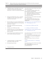
for Fujitsu M10/SPARC M10 Systems
Service Manual
Manual Code: C120-0008-01EN
November 2014
Copyright © 2007, 2014, Fujitsu Limited. All rights reserved.
Oracle and/or its affiliates provided technical input and review on portions of this material.
Oracle and/or its affiliates and Fujitsu Limited each own or control intellectual property rights relating to products and technology described in this document, and such products,
technology and this document are protected by copyright laws, patents, and other intellectual property laws and international treaties.
This document and the product and technology to which it pertains are distributed under licenses restricting their use, copying, distribution, and decompilation. No part of such
product or technology, or of this document, may be reproduced in any form by any means without prior written authorization of Oracle and/or its affiliates and Fujitsu Limited, and
their applicable licensors, if any. The furnishings of this document to you does not give you any rights or licenses, express or implied, with respect to the product or technology to
which it pertains, and this document does not contain or represent any commitment of any kind on the part of Oracle or Fujitsu Limited or any affiliate of either of them.
This document and the product and technology described in this document may incorporate third-party intellectual property copyrighted by and/or licensed from the suppliers to
Oracle and/or its affiliates and Fujitsu Limited, including software and font technology.
Per the terms of the GPL or LGPL, a copy of the source code governed by the GPL or LGPL, as applicable, is available upon request by the End User. Please contact Oracle and/or its
affiliates or Fujitsu Limited. This distribution may include materials developed by third parties. Parts of the product may be derived from Berkeley BSD systems, licensed from the
University of California.
UNIX is a registered trademark of The Open Group.
Oracle and Java are registered trademarks of Oracle and/or its affiliates.
Fujitsu and the Fujitsu logo are registered trademarks of Fujitsu Limited.
SPARC Enterprise, SPARC64, SPARC64 logo and all SPARC trademarks are trademarks or registered trademarks of SPARC International, Inc. in the United States and other
countries and used under license.
Other names may be trademarks of their respective owners.
If this is software or related documentation that is delivered to the U.S. Government or anyone licensing it on behalf of the U.S. Government, the following notice is applicable:
U.S. GOVERNMENT END USERS: Oracle programs, including any operating system, integrated software, any programs installed on the hardware, and/or documentation, delivered
to U.S. Government end users are "commercial computer software" pursuant to the applicable Federal Acquisition Regulation and agency-specific supplemental regulations. As such,
use, duplication, disclosure, modification, and adaptation of the programs, including any operating system, integrated software, any programs installed on the hardware, and/or
documentation, shall be subject to license terms and license restrictions applicable to the programs. No other rights are granted to the U.S. Government.
Disclaimer: The only warranties granted by Oracle and Fujitsu Limited, and/or any affiliate in connection with this document or any product or technology described herein are those
expressly set forth in the license agreement pursuant to which the product or technology is provided.
EXCEPT AS EXPRESSLY SET FORTH IN SUCH AGREEMENT, ORACLE OR FUJITSU LIMITED, AND/OR THEIR AFFILIATES MAKE NO REPRESENTATIONS OR WARRANTIE
S OF ANY KIND (EXPRESS OR IMPLIED) REGARDING SUCH PRODUCT OR TECHNOLOGY OR THIS DOCUMENT, WHICH ARE ALL PROVIDED AS IS, AND ALL EXPRESS
OR IMPLIED CONDITIONS, REPRESENTATIONS AND WARRANTIES, INCLUDING WITHOUT LIMITATION ANY IMPLIED WARRANTY OF MERCHANTABILITY, FITNESS
FOR A PARTICULAR PURPOSE OR NONINFRINGEMENT, ARE DISCLAIMED, EXCEPT TO THE EXTENT THAT SUCH DISCLAIMERS ARE HELD TO BE LEGALLY INVALID.
Unless otherwise expressly set forth in such agreement, to the extent allowed by applicable law, in no event shall Oracle or Fujitsu Limited, and/or any of their affiliates have any
liability to any third party under any legal theory for any loss of revenues or profits, loss of use or data, or business interruptions, or for any indirect, special, incidental or
consequential damages, even if advised of the possibility of such damages.
DOCUMENTATION IS PROVIDED "AS IS" AND ALL EXPRESS OR IMPLIED CONDITIONS, REPRESENTATIONS AND WARRANTIES, INCLUDING ANY IMPLIED
WARRANTY OF MERCHANTABILITY, FITNESS FOR A PARTICULAR PURPOSE OR NON-INFRINGEMENT, ARE DISCLAIMED, EXCEPT TO THE EXTENT THAT SUCH
DISCLAIMERS ARE HELD TO BE LEGALLY INVALID.
Copyright © 2007, 2014, Fujitsu Limited. Tous droits réservés.
Oracle et/ou ses affiliés ont fourni et vérifié des données techniques de certaines parties de ce composant.
Oracle et/ou ses affiliés et Fujitsu Limited détiennent et contrôlent chacun des droits de propriété intellectuelle relatifs aux produits et technologies décrits dans ce document. De
même, ces produits, technologies et ce document sont protégés par des lois sur le droit d’auteur, des brevets, et d'autres lois sur la propriété intellectuelle et des traités internationaux.
Ce document, le produit et les technologies afférents sont exclusivement distribués avec des licences qui en restreignent l'utilisation, la copie, la distribution et la décompilation.
Aucune partie de ce produit, de ces technologies ou de ce document ne peut être reproduite sous quelque forme que ce soit, par quelque moyen que ce soit, sans l'autorisation écrite
préalable d'Oracle et/ou ses affiliés et de Fujitsu Limited, et de leurs éventuels concédants de licence. Ce document, bien qu'il vous ait été fourni, ne vous confère aucun droit et
aucune licence, exprès ou tacites, concernant le produit ou la technologie auxquels il se rapporte. Par ailleurs, il ne contient ni ne représente aucun engagement, de quelque type que
ce soit, de la part d'Oracle ou de Fujitsu Limited, ou des sociétés affiliées de l'une ou l'autre entité.
Ce document, ainsi que les produits et technologies qu'il décrit, peuvent inclure des droits de propriété intellectuelle de parties tierces protégés par le droit d’auteur et/ou cédés sous
licence par des fournisseurs à Oracle et/ou ses sociétés affiliées et Fujitsu Limited, y compris des logiciels et des technologies relatives aux polices de caractères.
Conformément aux conditions de la licence GPL ou LGPL, une copie du code source régi par la licence GPL ou LGPL, selon le cas, est disponible sur demande par l'Utilisateur Final.
Veuillez contacter Oracle et/ou ses affiliés ou Fujitsu Limited. Cette distribution peut comprendre des composants développés par des parties tierces. Des parties de ce produit
pourront être dérivées des systèmes Berkeley BSD licenciés par l'Université de Californie.
UNIX est une marque déposée de The OpenGroup.
Oracle et Java sont des marques déposées d'Oracle Corporation et/ou de ses affiliés.
Fujitsu et le logo Fujitsu sont des marques déposées de Fujitsu Limited.
SPARC Enterprise, SPARC64, le logo SPARC64 et toutes les marques SPARC sont utilisées sous licence et sont des marques déposées de SPARC International, Inc., aux Etats-Unis et
dans d'autres pays.
Tout autre nom mentionné peut correspondre à des marques appartenant à leurs propriétaires respectifs.
Si ce logiciel, ou la documentation qui l'accompagne, est concédé sous licence au Gouvernement des Etats-Unis, ou à toute entité qui délivre la licence de ce logiciel ou l'utilise pour le
compte du Gouvernement des Etats-Unis, la notice suivante s'applique :
U.S. GOVERNMENT END USERS: Oracle programs, including any operating system, integrated software, any programs installed on the hardware, and/or documentation, delivered
to U.S. Government end users are "commercial computer software" pursuant to the applicable Federal Acquisition Regulation and agency-specific supplemental regulations. As such,
use, duplication, disclosure, modification, and adaptation of the programs, including any operating system, integrated software, any programs installed on the hardware, and/or
documentation, shall be subject to license terms and license restrictions applicable to the programs. No other rights are granted to the U.S. Government.
Avis de non-responsabilité : les seules garanties octroyées par Oracle et Fujitsu Limited et/ou toute société affiliée de l'une ou l'autre entité en rapport avec ce document ou tout
produit ou toute technologie décrits dans les présentes correspondent aux garanties expressément stipulées dans le contrat de licence régissant le produit ou la technologie fournis.
SAUF MENTION CONTRAIRE EXPRESSEMENT STIPULEE AU DIT CONTRAT, ORACLE OU FUJITSU LIMITED ET/OU LES SOCIETES AFFILIEES A L'UNE OU L'AUTRE
ENTITE DECLINENT TOUT ENGAGEMENT OU GARANTIE, QUELLE QU'EN SOIT LA NATURE (EXPRESSE OU IMPLICITE) CONCERNANT CE PRODUIT, CETTE
TECHNOLOGIE OU CE DOCUMENT, LESQUELS SONT FOURNIS EN L'ETAT. EN OUTRE, TOUTES LES CONDITIONS, DECLARATIONS ET GARANTIES EXPRESSES OU
TACITES, Y COMPRIS NOTAMMENT TOUTE GARANTIE IMPLICITE RELATIVE A LA QUALITE MARCHANDE, A L'APTITUDE A UNE UTILISATION PARTICULIERE OU A
L'ABSENCE DE CONTREFACON, SONT EXCLUES, DANS LA MESURE AUTORISEE PAR LA LOI APPLICABLE. Sauf mention contraire expressément stipulée dans ce contrat,
dans la mesure autorisée par la loi applicable, en aucun cas Oracle ou Fujitsu Limited et/ou l'une ou l'autre de leurs sociétés affiliées ne sauraient être tenues responsables envers une
quelconque partie tierce, sous quelque théorie juridique que ce soit, de tout manque à gagner ou de perte de profit, de problèmes d'utilisation ou de perte de données, ou
d'interruptions d'activités, ou de tout dommage indirect, spécial, secondaire ou consécutif, même si ces entités ont été préalablement informées d'une telle éventualité.
LA DOCUMENTATION EST FOURNIE "EN L'ETAT" ET TOUTE AUTRE CONDITION, DECLARATION ET GARANTIE, EXPRESSE OU TACITE, EST FORMELLEMENT
EXCLUE, DANS LA MESURE AUTORISEE PAR LA LOI EN VIGUEUR, Y COMPRIS NOTAMMENT TOUTE GARANTIE IMPLICITE RELATIVE A LA QUALITE MARCHANDE,
A L'APTITUDE A UNE UTILISATION PARTICULIERE OU A L'ABSENCE DE CONTREFACON.
Contents
Preface
xi
Chapter 1
Before Starting Maintenance Work
1.1
Warning/Caution Indications
1.2
Labels/Tags
1.3
Safety Precautions
1.4
Notes Regarding Static Electricity
1.5
Other Precautions
1.6
Emergency Power Off
Chapter 2
1
1
2
3
4
5
6
Understanding the System Components
7
2.1
Identifying the Names and Locations of Components
2.2
Confirming the Functions of the Operation Panel
2.3
2.4
2.2.1
Display function of the operation panel
12
2.2.2
Control function of the operation panel
12
Checking the LED Indications
Operation panel LEDs
2.3.2
LEDs on the rear panel (System locator)
2.3.3
LEDs on each component
15
Confirming the Types of Cable
Types of cable
2.4.2
Cable connection ports
Chapter 3
10
15
2.3.1
2.4.1
7
16
17
19
19
Types of Maintenance
20
21
iii
3.1
Types of Maintenance Supported for the Crossbar Box
3.2
Active Maintenance
3.3
Inactive Maintenance
3.4
System-stopped Maintenance
Chapter 4
4.1
4.2
4.3
22
23
24
Preparation and Precautions for Maintenance
Confirming the System Configuration
27
27
4.1.1
Confirming the hardware configuration
4.1.2
Confirming the software and firmware configurations
4.1.3
Confirming the FRU information and resource information
Troubleshooting
27
28
29
30
4.2.1
Determining the causes of failures
4.2.2
Identifying a failure
4.2.3
Downloading error log information
Maintenance Precautions
30
31
36
37
4.3.1
Precautions for replacement
4.3.2
Precautions for installation
4.3.3
Precautions for removal
Chapter 5
37
39
39
Enabling the Removal of an FRU Requiring Maintenance
41
5.1
Preparing Tools Required for Maintenance
5.2
Releasing a Chassis of the Physical Partition to Connect to, from the
System
5.2.1
41
42
Checking the operating condition of the physical partition or
logical domain
42
5.2.2
Enabling maintenance on the system
5.2.3
Releasing the chassis of the physical partition to connect to, from
the physical partition
43
43
5.2.4
Powering off the physical partition to connect to
5.2.5
Stopping the entire system
46
5.3
Saving XSCF Setting Information
48
5.4
Releasing FRUs of the Crossbar Box from the System with the
replacefru Command
iv
21
49
Crossbar Box for Fujitsu M10/SPARC M10 Systems Service Manual ・ November 2014
45
5.4.1
Releasing FRUs of the crossbar box with the replacefru
command
5.4.2
5.5
6.2
Releasing the FRU of the chassis of the physical partition
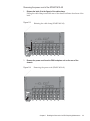
Accessing an FRU
Removing the power cord
53
5.5.2
Removing the front cover
56
Restoring the System
Restoring the Chassis
57
57
6.1.1
Installing the power cord
57
6.1.2
Installing the front cover
59
Incorporating the FRUs of the Crossbar Box into the System with the
replacefru Command
60
6.2.1
Restoring the crossbar box with the replacefru command
6.2.2
Restoring the FRUs of the chassis of the physical Partition
6.3
Diagnosing the Crossbar Unit and Crossbar Cables
6.4
Restoring XSCF Setting Information
6.5
Incorporating a Chassis into a Physical Partition
6.6
Making the System Normal Operation State
6.7
Powering On the Physical Partition Requiring Maintenance
6.8
Starting the Entire System
65
67
68
68
69
6.8.2
Starting the system from the operation panel
70
71
7.1
Maintenance Workflow and Type of Maintenance
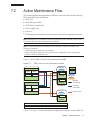
7.2
Active Maintenance Flow
7.3
Inactive Maintenance Flow
7.4
System-stopped Maintenance Flow
90
96
System-stopped/hot maintenance
7.4.2
System-stopped/cold maintenance
Maintaining the XSCF Unit
Location of the XSCF Unit
72
75
7.4.1
Chapter 8
62
65
Starting the system with an XSCF command
Maintenance Flow
61
64
6.8.1
Chapter 7
8.1
51
53
5.5.1
Chapter 6
6.1
49
96
97
101
101
Contents
v
8.2
Before Maintaining the XSCF Unit
102
8.2.1
102
8.3
Removing the XSCF Unit
8.4
Switching the microSD Card
8.5
Installing the XSCF Unit
Chapter 9
102
105
110
Maintaining the XSCF BB Control Cables
111
9.1
Configuration of the Ports for the XSCF BB Control Cables
9.2
Removing an XSCF BB Control Cable
9.3
Installing an XSCF BB Control Cable
Chapter 10
111
113
114
Maintaining the XSCF DUAL Control Cables
10.1
Configuration of the XSCF DUAL Control Ports
10.2
Removing an XSCF DUAL Control Cable
10.3
Installing an XSCF DUAL Control Cable
Chapter 11
117
117
118
119
Maintaining the Crossbar Cables (Optical)
121
11.1
Configuration of the Ports for the Crossbar Cables (Optical)
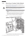
11.2
Removing a Crossbar Cable (Optical)
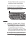
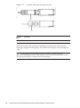
11.3
Installing a Crossbar Cable (Optical)
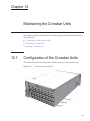
Chapter 12
Maintaining the Crossbar Units
124
125
127
12.1
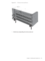
Configuration of the Crossbar Units
12.2
Removing a Crossbar Unit
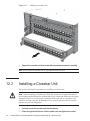
12.3
Installing a Crossbar Unit
Chapter 13
127
128
130
Maintaining the Power Supply Units
133
13.1
Configuration of the Power Supply Units
133
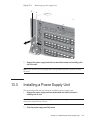
13.2
Removing a Power Supply Unit
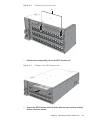
13.3
Installing a Power Supply Unit
Chapter 14
134
135
Maintaining the XSCF Interface Unit
137
14.1
Location of the XSCF Interface Unit
14.2
Before Maintaining the XSCF Interface Unit
14.2.1
vi
Precautions for maintenance
137
Precautions for maintenance
138
14.3
Removing the XSCF Interface Unit
138
14.4
Installing the XSCF Interface Unit
140
Crossbar Box for Fujitsu M10/SPARC M10 Systems Service Manual ・ November 2014
138
121
Chapter 15
Maintaining the Fan Units
141
15.1
Configuration of the Fan Units
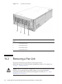
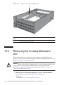
15.2
Removing a Fan Unit
15.3
141
142
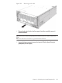
15.2.1
Accessing a fan unit
143
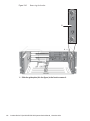
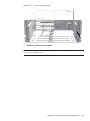
15.2.2
Removing a fan unit
143
Installing a Fan Unit
143
15.3.1
Installing a fan unit
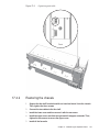
15.3.2
Restoring the chassis
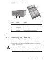
Chapter 16
144
144
Maintaining the Fan Backplane
16.1
Configuration of the Fan Backplane
16.2
Removing the Fan Backplane
16.3
145
145
146
16.2.1
Accessing the fan backplane
147
16.2.2
Removing the fan backplane
147
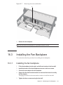
Installing the Fan Backplane
151
16.3.1
Installing the fan backplane
16.3.2
Restoring the chassis
Chapter 17
151
152
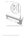
Maintaining the Operation Panel
153
17.1
Location of the Operation Panel
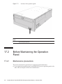
17.2
Before Maintaining the Operation Panel
17.2.1
17.3
17.4
Maintenance precautions
154
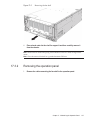
Removing the Operation Panel
155
154
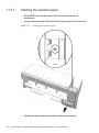
17.3.1
Accessing the operation panel
155
17.3.2
Removing the operation panel
157
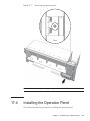
Installing the Operation Panel
159
17.4.1
Installing the operation panel
17.4.2
Restoring the chassis
Chapter 18
18.1
153
161
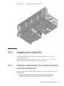
Maintaining the Cable Kit
Configuration of the Cable Kit
18.1.1
160
163
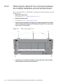
163
Cables for the connection between the crossbar backplane unit
and terminal board
163
Contents
vii
18.1.2
Cables for the connection between the terminal board and fan
backplane
18.1.3
18.2
165
Locations for the cable kit
Removing the Cable Kit
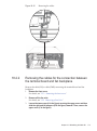
18.2.1
166
167
Removing the cables for the connection between the crossbar
backplane unit and terminal board
18.2.2
Removing the cables for the connection between the terminal
board and fan backplane
18.3
Installing the Cable Kit
18.3.1
181
181
Installing a cable for the connection between the terminal board
and fan backplane
Chapter 19
173
Installing a cable between the crossbar backplane unit and
terminal board
18.3.2
182
Maintaining the Crossbar Backplane Unit
19.1
Location of the Crossbar Backplane Unit
19.2
Removing the Crossbar Backplane Unit
19.3
Installing the Crossbar Backplane Unit
Chapter 20
189
189
190
197
Maintaining the Dedicated Power Distribution Unit Mounted on
the Rack for Expanded Connection
20.1
168
199
Configuration of the Dedicated Power Distribution Unit
20.1.1
199
CB switches on the dedicated power distribution unit
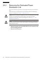
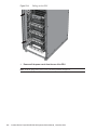
20.2
Removing the Dedicated Power Distribution Unit
20.3
Installing the Dedicated Power Distribution Unit
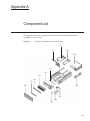
Appendix A
Component List
207
Appendix B
Component Specifications
B.1
Crossbar Unit
211
B.2
XSCF Unit
B.3
XSCF Interface Unit
B.4
Power Supply Unit
B.5
Fan Unit
B.6
Backplanes
211
212
212
213
213
214
viii Crossbar Box for Fujitsu M10/SPARC M10 Systems Service Manual ・ November 2014
202
206
201
B.7
Operation Panel
Appendix C
C.1
External Interface Specifications
Serial Port
C.1.1
217
217
Wire connection chart for serial cable
C.2
USB Port
C.3
RESET Switch
Index
216
218
218
218
221
Contents
ix
x
Crossbar Box for Fujitsu M10/SPARC M10 Systems Service Manual ・ November 2014
Preface
This document describes the maintenance procedure for the crossbar box used in the
Fujitsu M10 systems. The maintenance work should be performed by service
engineers and/or field engineers.
Fujitsu M10 is sold as SPARC M10 Systems by Fujitsu in Japan.
Fujitsu M10 and SPARC M10 Systems are identical products.
The preface includes the following sections:
Audience
■
■
Related Documentation
■
Text Conventions
■
Notes on Safety
■
Syntax of the Command-Line Interface (CLI)
■
Document Feedback
Audience
This document is intended for service engineers and field engineers who perform
maintenance work on the system.
xi
Related Documentation
All documents for your server are available online at the following locations.
Sun Oracle software-related documents (Oracle Solaris, etc.)
http://www.oracle.com/documentation/
■
■
Fujitsu documents
Japanese site
http://jp.fujitsu.com/platform/server/sparc/manual/
Global site
http://www.fujitsu.com/global/services/computing/server/sparc/downloads/manual/
The following table lists documents related to SPARC M10 Systems.
Documentation Related to SPARC M10 Systems (*1)
Fujitsu M10/SPARC M10 Systems Getting Started Guide (*2)
Fujitsu M10/SPARC M10 Systems Quick Guide
Fujitsu M10/SPARC M10 Systems Important Legal and Safety Information (*2)
Software License Conditions for Fujitsu M10/SPARC M10 Systems
Fujitsu M10/SPARC M10 Systems Safety and Compliance Guide
Fujitsu M10/SPARC M10 Systems Security Guide
Fujitsu M10/SPARC M10 Systems/SPARC Enterprise/PRIMEQUEST Common Installation Planning Manual
Fujitsu M10/SPARC M10 Systems Installation Guide
Fujitsu M10-1/SPARC M10-1 Service Manual
Fujitsu M10-4/Fujitsu M10-4S/SPARC M10-4/SPARC M10-4S Service Manual
Crossbar Box for Fujitsu M10/SPARC M10 Systems Service Manual
PCI Expansion Unit for Fujitsu M10/SPARC M10 Systems Service Manual
Fujitsu M10/SPARC M10 Systems PCI Card Installation Guide
Fujitsu M10/SPARC M10 Systems System Operation and Administration Guide
Fujitsu M10/SPARC M10 Systems Domain Configuration Guide
Fujitsu M10/SPARC M10 Systems XSCF Reference Manual
Fujitsu M10/SPARC M10 Systems RCIL User Guide (*3)
Fujitsu M10/SPARC M10 Systems XSCF MIB and Trap Lists
Fujitsu M10/SPARC M10 Systems Product Notes
Fujitsu M10/SPARC M10 Systems Glossary
*1: The listed manuals are subject to change without notice.
*2: Printed manuals are provided with the product.
*3: This document applies specifically to the FUJITSU M10 and FUJITSU ETERNUS storage system.
xii
Crossbar Box for Fujitsu M10/SPARC M10 Systems Service Manual ・ November 2014
Text Conventions
This manual uses the following fonts and symbols to express specific types of
information.
Font/Symbol
Meaning
Example
AaBbCc123
What you type, when contrasted with on-screen
computer output.
This font indicates an example of command input.
XSCF> adduser jsmith
AaBbCc123
The names of commands, files, and directories;
on-screen computer output.
This font indicates an example of command input
in the frame.
XSCF> showuser -P
User Name:
jsmith
Privileges:
useradm
auditadm
Italic
Indicates the name of a reference manual.
See the Fujitsu M10/SPARC M10
Systems Installation Guide.
""
Indicates the names of chapters, sections, items,
buttons, or menus.
See "Chapter 2 Network Connection."
Command syntax in the text
While the XSCF commands have a section number of (8) or (1), it is omitted from the
text.
The Oracle Solaris commands have a section number such as (1M) in the text.
Each command has a section number in a command name to prompt users to refer to
it.
Notes on Safety
Read the following documents thoroughly before using or handling any SPARC M10
Systems.
■
Fujitsu M10/SPARC M10 Systems Important Legal and Safety Information
■
Fujitsu M10/SPARC M10 Systems Safety and Compliance Guide
Preface
xiii
Syntax of the Command-Line Interface
(CLI)
The command syntax is as follows:
A variable that requires the input of a value must be put in Italics.
■
■
■
An optional element must be enclosed in [].
A group of options for an optional keyword must be enclosed in [] and delimited
by |.
Document Feedback
If you have any comments or requests regarding this document, please take a
moment to share it with us by indicating the manual code, manual title, and page,
and stating your points specifically through the following websites:
■
Japanese site
http://jp.fujitsu.com/platform/server/sparc/manual/
■
Global site
http://www.fujitsu.com/global/services/computing/server/sparc/downloads/manual/
xiv Crossbar Box for Fujitsu M10/SPARC M10 Systems Service Manual ・ November 2014
Chapter 1
Before Starting Maintenance Work
This chapter describes the safety precautions that must be observed before starting
any maintenance work.
Note the meanings of each of the following symbols and labels to ensure that the
work is done correctly.
■
Warning/Caution Indications
1.1
■
Labels/Tags
■
Safety Precautions
■
Notes Regarding Static Electricity
■
Other Precautions
■
Emergency Power Off
Warning/Caution Indications
This manual uses the following conventions to indicate warning and alert messages,
which are intended to prevent injury to the user and others as well as damage to
property.
Warning - "WARNING" indicates a potential hazard that could result in death or
serious personal injury if the user does not perform the procedure correctly.
Caution - "CAUTION" indicates a potential hazard that could result in minor or
moderate personal injury if the user does not perform the procedure correctly. This
also indicates that damage to the unit or other property may occur if the user does
not perform the procedure correctly.
1
1.2
Labels/Tags
This section describes the labels and tags that are affixed on the crossbar box chassis.
When performing maintenance, always observe the precautions on the standard
labels attached to the chassis.
Caution - Do not remove the labels or tags.
Note - The contents of the labels and tags described here may differ from those actually
attached to the chassis.
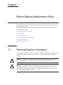
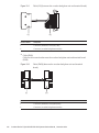
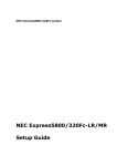
■
■
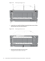
The system name plate label (A in the figure) describes the model number, serial
number, manufacture date, and weight required for maintenance and management.
The standard label (B in the figure) contains notes, rated voltage/current, number
of phases, frequency, and the following certification standards.
- Safety: NRTL/C
- Radio wave: VCCI-A, FCC-A, DOC-A, KCC, and C-Tick
- Safety and radio wave: CE and EAC
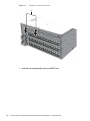
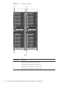
Figure 1-1
Location of the system name plate label and standard label
A
B
■
2
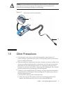
The RFID tag (Figure 1-2) carries an Asset ID. The RFID tag is affixed on the front
cover.
Crossbar Box for Fujitsu M10/SPARC M10 Systems Service Manual ・ November 2014
Figure 1-2
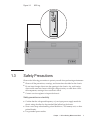
1.3
RFID tag
Safety Precautions
Observe the following precautions to protect yourself when performing maintenance.
■
Observe all the precautions, warnings, and instructions described on the chassis.
■
■
Do not insert foreign objects into the openings in the chassis. Any such foreign
object could come into contact with high-voltage circuitry or could short circuit
the components, causing a fire or an electric shock.
Contact a service engineer to inspect the chassis.
Safety precautions on electricity
■
■
■
Confirm that the voltage and frequency of your input power supply match the
electric rating described on the standard label affixed on the chassis.
Wear a wrist strap when handling a hard disk drive, CPU memory unit, or other
printed boards.
Use grounded power outlets.
Chapter 1
Before Starting Maintenance Work
3
■
Do not attempt to make any mechanical or electrical modifications. Fujitsu shall
not be responsible for the regulatory compliance of a chassis that has been modified.
Safety precautions on the racks
■
■
■
■
The racks should be fixed on the floor, ceiling, or the adjacent frame.
The racks may be supplied with a quakeresistant options kit. The use of the
quakeresistant options kit prevents the racks from falling over during installation
or maintenance service on the chassis.
Prior to installation or maintenance, a safety assessment should be conducted by a
service engineer in the following cases:
■
When the quakeresistant options kit is not supplied and the rack is not fixed on
the floor with bolts: Check for the safety such as whether the rack should not
fall over.
If multiple chassis are mounted in a rack, perform maintenance for each of the
chassis.
For details of the racks, see "Chapter 2 Planning and Preparing for System
Installation" in the Fujitsu M10/SPARC M10 Systems Installation Guide.
1.4
Notes Regarding Static Electricity
Observe the precautions concerning the electrostatic discharge (ESD) as described in
Table 1-1 to ensure the safety of personnel and the system.
Table 1-1
ESD precautions
Item
Precaution
Wrist strap
Wear an antistatic wrist strap when handling printed boards.
ESD mat
An approved ESD mat provides protection from static damage
when used with a wrist strap. The mat also acts as a cushion to
protect the small parts that are attached to printed boards.
Antistatic bag/
ESD safe packaging box
After removing a printed board or component, place it in the
antistatic bag or ESD safe packaging box.
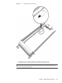
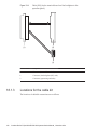
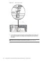
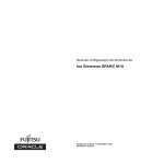
How to use a wrist strap
Wear a wrist strap in such a way that the inner metal surface (A in the figure) of the
wrist strap band is in contact with your skin. Connect the clip (B in the figure)
directly to the chassis.
4
Crossbar Box for Fujitsu M10/SPARC M10 Systems Service Manual ・ November 2014
Caution - Do not connect the wrist strap clip to the ESD mat. By connecting the wrist
strap clip to the chassis, the operator and components have the same level of
potential, thus eliminating the danger of static damage.
Figure 1-3
Wrist strap connection destination
A
B
1.5
Other Precautions
■
■
■
Printed boards in the chassis can be easily damaged by static electricity. To
prevent damage to printed boards, wear a wrist strap and ground it to the chassis
prior to starting maintenance.
When mounting any component in the chassis, check the connectors on both of the
chassis and component beforehand to confirm that none of the pins are bent and
that all the pins are neatly arranged in lines. If a component is mounted with a
bent pin in a connector, the chassis or component may be damaged. Also, carefully
proceed with the work to prevent any pin from being bent.
If excessive force is applied to the CPU memory unit, the components mounted on
printed boards may be damaged. When handling the CPU memory unit, observe
the following precautions:
■
Hold the CPU memory unit by the metal frame.
■
When removing the CPU memory unit from the packaging, keep the CPU
memory unit horizontal until you lay it on the cushioned ESD mat.
Chapter 1
Before Starting Maintenance Work
5
■
■
■
■
■
1.6
Connectors and components on the CPU memory unit have thin pins that bend
easily. Therefore, do not place the CPU memory unit on a hard surface.
Be careful not to damage the small parts located on both sides of the CPU
memory unit.
The heat sinks can be damaged by incorrect handling. Do not touch the heat sinks
with your hands or other objects while replacing or removing CPU memory units.
If a heat sink is disconnected or broken, obtain a replacement CPU memory unit.
When storing or carrying a CPU memory unit, ensure that the heat sinks are
sufficiently protected.
When removing a cable such as the LAN cable, if you cannot reach the latch lock
of the connector, use a flat headed screwdriver etc. to push the latch and release
the cable. If you use force to remove the cable, the LAN port of the CPU memory
unit or the PCI Express (PCIe) cards may be damaged.
Do not use any power cord other than the specified one.
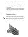
Emergency Power Off
This section explains the procedure for powering off the system in an emergency.
Caution - In an emergency (such as smoke or flames coming from the chassis),
immediately stop using the unit and turn off the power supply. Regardless of the
operation you are performing, give top priority to fire prevention.
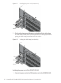
1.
Remove all the power cords from the power supply unit.
Figure 1-4
6
Removing the power cords
Crossbar Box for Fujitsu M10/SPARC M10 Systems Service Manual ・ November 2014
Chapter 2
Understanding the System
Components
This chapter describes the components mounted in the crossbar box.
It is necessary to confirm and fully understand the configurations of the components
mounted in the crossbar box as well as the LED indications before starting any
maintenance work.
■
Identifying the Names and Locations of Components
■
Confirming the Functions of the Operation Panel
■
Checking the LED Indications
■
Confirming the Types of Cable
For the specifications of each component, see "Appendix B Component Specifications."
Note that the terms used in this manual are defined as follows:
Table 2-1
2.1
Definitions of terms
Term
Definition
Chassis of the physical partition
Chassis of SPARC M10-4S that make up the physical
partition (the crossbar box is not included)
FRU
Component that can be replaced by a field engineer
(abbreviation of field replaceable unit)
Identifying the Names and Locations of
Components
This section describes the names and the locations of components mounted in the
crossbar box.
Components that can be accessed from the front
You can access the fan unit only after removing the front cover.
7
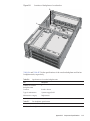
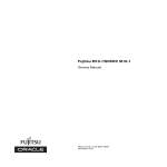
Figure 2-1
Location of components that can be accessed from the front
(1)
Location number
Component
1
Fan unit
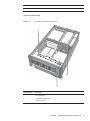
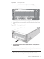
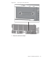
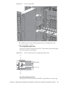
Components that can be accessed from the rear
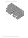
Figure 2-2
Location of components that can be accessed from the rear
(2)
(1)
8
(3)
(4)
Location number
Component
1
Power supply unit
2
XSCF unit
3
XSCF interface unit
Crossbar Box for Fujitsu M10/SPARC M10 Systems Service Manual ・ November 2014
Location number
Component
4
Crossbar unit
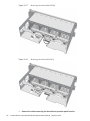
Internal components
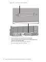
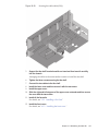
Figure 2-3
Locations of internal components
(1)
(2)
(3)
Location number
Component
1
Fan backplane
2
Crossbar backplane unit
3
Operation panel
Chapter 2
Understanding the System Components
9
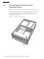
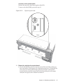
2.2
Confirming the Functions of the
Operation Panel
This section describes the functions of the operation panel mounted in the crossbar
box.
The operation panel provides the system's display and control functions. A field
engineer and the system administrator can specify the operation mode or control the
starting/stopping of the system while checking the system operation status by
referring to the LED indications.
Figure 2-4
10
Location of the operation panel
Crossbar Box for Fujitsu M10/SPARC M10 Systems Service Manual ・ November 2014
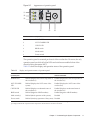
Figure 2-5
Appearance of operation panel
㩿㪈㪀
㩿㪉㪀
㩿㪊㪀
㩿㪋㪀
㩿㪌㪀
Location number
Component
1
POWER LED
2
XSCF STANDBY LED
3
CHECK LED
4
BB-ID switch
5
Mode switch
6
Power switch
㩿㪍㪀
The operation panel is mounted per chassis of the crossbar box. However, the only
operation panel on which all of the LEDs and switches are enabled is that of the
chassis housing the master XSCF.
Table 2-2 shows the display and operation status of the operation panel.
Table 2-2
Display and operation status of operation panel
LEDs/switches on
operation panel
When the crossbar box is acting as the master XSCF
When the crossbar box is acting as an XSCF other
than the master XSCF
POWER LED
Enabled (Displays the start or stop status of
the crossbar box)
Enabled (Displays the start or stop status of
the crossbar box)
XSCF STANDBY
LED
Enabled (Displays the XSCF status of the
system)
Enabled (Displays the XSCF status of the
crossbar box)
CHECK LED
Enabled (Displays an abnormal status of
the crossbar box)
Enabled (Displays an abnormal status of
the crossbar box)
BB-ID switch
Enabled (Registers a BB-ID number)
Enabled (Registers a BB-ID number)
Mode switch (*)
Enabled (Mode operation of the system)
Disabled
Power switch
Enabled (Start/stop operation of the system)
Disabled
*: Set the same mode for the crossbar boxes with the master XSCF and XSCF in the standby state. If the settings are different, an asterisk
(*) is displayed beside the components in the output of the showhardconf or showstatus command.
Chapter 2
Understanding the System Components
11
2.2.1
Display function of the operation panel
The operation panel has three LED indicators to implement its display function. The
LED indicators indicate the following. For details, see "2.3.1 Operation panel LEDs."
■
General system status
■
System error warning
■
System error location
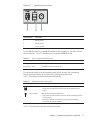
Figure 2-6
Operation panel LEDs
㩿㪈㪀
㩿㪉㪀
㩿㪊㪀
2.2.2
Location number
Component
1
POWER LED
2
XSCF STANDBY LED
3
CHECK LED
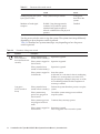
Control function of the operation panel
The operation panel has the following switches to implement its control function:
BB-ID switch
Identifies the crossbar box.
■
■
■
12
Mode switch (slide switch)
Specifies the operation or maintenance mode.
Power switch
Controls start/stop of the system.
Crossbar Box for Fujitsu M10/SPARC M10 Systems Service Manual ・ November 2014
Figure 2-7
Operation panel switches
㩿㪉㪀
㩿㪈㪀
㩿㪊㪀
Location number
Component
1
BB-ID switch
2
Mode switch
3
Power switch
Use the BB-ID switch to set the BB-ID number of the crossbar box. Set #80 to #83 for
the crossbar box. Table 2-3 describes how to operate the BB-ID switch.
Table 2-3
How to operate the BB-ID switch
Operation
Description
Pressing the + side
The BB-ID number increases by 1.
Pressing the - side
The BB-ID number decreases by 1.
Use the mode switch to set the operation mode for the system. The Locked and
Service operation modes can be switched by sliding the mode switch.
Table 2-4 describes the difference between the modes.
Table 2-4
Icon
Operation modes for the system
Name
Description
Locked mode
This mode is used for normal operation.
- The power switch can be used to start the system but not to
stop it.
Service mode
This mode is used for maintenance.
- The power switch cannot be used to start the system but can be
used to stop it.
- Place the system in Service mode to perform maintenance
work with the system stopped.
Table 2-5 describes the functions of the mode switch.
Chapter 2
Understanding the System Components
13
Table 2-5
Functions of the mode switch
Function
Mode switch
Locked
Service
Starting/Stopping the system
by the power switch
Only system startup is enabled.
A long press
shuts down the
system.
Inhibition of break signal
reception
Enabled. Using the setpparmode
command, it is possible to specify
whether break signal reception is
allowed or inhibited for each physical
partition.
Disabled
Use the power switch to start or stop the system. The system starts/stops differently
depending on how the power switch is pressed.
Table 2-6 describes how system starts/stops vary depending on how the power
switch is pressed.
Table 2-6
Icon
Functions of the power switch
Operation
Description
Brief press
(For 1 second or
more and less than 4
seconds)
If the system has been
started in Service mode (*):
Operation is ignored.
If the system is stopped in
Service mode:
Operation is ignored.
If the system has been
started in Locked mode (*):
Operation is ignored.
If the system is stopped in
Locked mode:
Starts the system.
At this time, if a wait time for the air conditioning
facilities or a warm-up time is set on the XSCF,
the processing for waiting for the power-on of the
air conditioning facilities and the completion of
warm-up is omitted.
If the system has been
started in Service mode (*):
Perform the system shutdown process to stop the
system.
If the system startup
process is in progress in
Service mode:
Cancels the system startup process and then
stops the system.
If the system stop process
is in progress in Service
mode:
Continues the system stop process.
If the system is stopped in
Service mode:
Operation is ignored.
Even a long press does not start the system.
Long press
(For 4 seconds or
more)
14
Crossbar Box for Fujitsu M10/SPARC M10 Systems Service Manual ・ November 2014
Table 2-6
Icon
Functions of the power switch (continued)
Operation
Description
If the system is stopped in
Locked mode:
Starts the system.
If a wait time for the air conditioning facilities or
a warm-up time is set on the XSCF, the
processing for waiting for the power-on of the air
conditioning facilities and the completion of
warm-up is omitted.
If the system is not
stopped in Locked mode:
Operation is ignored.
*: If the system has been started, it means that at least one physical partition has been powered on.
2.3
Checking the LED Indications
This section describes the statuses of the LEDs mounted on the crossbar box.
LEDs are mounted on the operation panel on the front of the chassis, on the rear
panel of the chassis, and on each component that can be maintained. If an error
occurs, the LED indication enables you to determine which system requires
maintenance.
2.3.1
Operation panel LEDs
The three LEDs on the operation panel indicate the operation status of the overall
system. In addition, the LEDs enable you to check the system status by their
combination of being on, blinking, or off.
Table 2-7 lists the system operation status indicated by the LEDs, while Table 2-8 lists
the system status indicated by the combination of LEDs.
Table 2-7
System operation status indicated by LEDs
Icon
Name
Color
Description
POWER
Green
Indicates the startup or stop status of the system for
each chassis.
●
On: System is started.
●
Off: System is stopped.
●
Blinking (*): System stop process is in progress.
XSCF
STANDBY
Green
Indicates the status of the XSCF for the entire system or
for each chassis.
●
On: XSCF is functioning normally.
●
Off: XSCF is stopped.
●
Blinking (*): System is being initialized after
power-on.
Chapter 2
Understanding the System Components
15
Table 2-7
System operation status indicated by LEDs (continue d)
Icon
Name
Color
Description
CHECK
Amber
Indicates the system operation status for each chassis.
●
On: An error that prevents startup was detected.
●
Off: Normal, or the power is disconnected or not
being supplied.
●
Blinking (*): Indicates that the chassis requires
maintenance (this function is also referred to as the
"locator").
*: The blink interval is 1 second (1 Hz).
Table 2-8
System status indicated by combination of LEDs
LED state
Description
POWER
XSCF
STANDBY
CHECK
Off
Off
Off
Power is disconnected.
Off
Off
On
Power has just been turned on.
The XSCF has detected an error.
Off
Blinking (*)
Off
The XSCF is being initialized.
Off
On
Off
The XSCF is in the standby state.
The system is waiting for power-on of the air
conditioning facilities (in the data center).
On
On
Off
Warm-up standby processing is in progress. After
the end of this processing, the system starts up.
System startup processing is in progress.
The system is operating.
On
On
On
The system is operating normally, but an error has
been detected.
Blinking (*)
On
Off
System stop processing is in progress. After the
end of processing, the fan unit stops.
* The blink interval is 1 second (1 Hz).
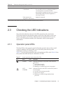
2.3.2
LEDs on the rear panel (System locator)
The field engineer or system administrator can identify the chassis requiring
maintenance by using the CHECK LED (A in the figure) on the rear panel. The
CHECK LED on the rear panel is referred to as the system locator, and has the same
function as the CHECK LED on the operation panel.
16
Crossbar Box for Fujitsu M10/SPARC M10 Systems Service Manual ・ November 2014
Figure 2-8
Location of the system locator
A
Table 2-9
Icon
Status of the system locator
Name
Color
Description
CHECK
Amber
Indicates the system operation status for each chassis.
●
On: An error that prevents startup was detected.
●
Off: Normal, or the power is disconnected or not being
supplied.
●
Blinking (*): Indicates that the chassis requires
maintenance (this function is also referred to as the
"locator").
*: The blink interval is 1 second (1 Hz).
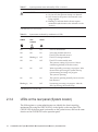
2.3.3
LEDs on each component
Each component of the crossbar box has an LED mounted. These LEDs light to
indicate that a component requires maintenance if that component experiences a
fault. Start maintenance work after checking the LED status.
The LEDs on each component and their statuses are as follows:
Chapter 2
Understanding the System Components
17
Table 2-10
LEDs on the XSCF or XSCF unit and their statuses
Name
Color
Status
Description
READY
Green
On
Indicates that the component is operating.
The component cannot be released and
removed from the system.
Blinking (*)
Indicates that the component is currently
being mounted on the system or being
disconnected from the system.
Off
Indicates that the component is disconnected
from the system. Indicates that the
component can be removed and replaced.
On
Indicates that an error has occurred.
Blinking (*)
Indicates that the component requires
maintenance (this function is also referred to
as the "locator").
Off
Indicates the normal state.
On
Master chassis
Off
Slave chassis
CHECK
MASTER
Amber
Green
*: The blink interval is 1 second (1 Hz).
Table 2-11
LEDs on the XSCF-LAN port and their statuses
Name
Color
Status
Description
ACT
Green
On
Indicates that communication is being
performed.
Off
Indicates that communication is not being
performed.
Amber
On
Indicates that the communication speed is 1
Gbps.
Green
Blinking (*)
Indicates that the communication speed is
100 Mbps.
Off
Indicates that the communication speed is 10
Mbps.
LINK SPEED
*: The blink interval is 1 second (1 Hz).
Table 2-12
LED on the fan unit and its states
Name
Color
Status
Description
CHECK
Amber
On
Indicates that an error has occurred.
Blinking (*)
Indicates that the component requires
maintenance (this function is also referred to
as the "locator").
Off
Indicates the normal state.
*: The blink interval is 1 second (1 Hz).
18
Crossbar Box for Fujitsu M10/SPARC M10 Systems Service Manual ・ November 2014
Table 2-13
Name
CHECK
LED on the power supply unit and its states
Color
Status
Description
Green
On
Indicates that the input power is turned on
and power is being supplied normally.
Blinking (*)
Indicates that the input power is being
disconnected.
On
Indicates that an error has occurred.
Indicates that the input power to this power
supply unit is turned off in redundant
operation.
Blinking (*)
Indicates a warning (An error has occurred
but this power supply unit is operating).
Off
Indicates that power is not being supplied.
Amber
*: The blink interval is 1 second (1 Hz).
2.4
Confirming the Types of Cable
This section describes the types of the cables that are connected to the crossbar box,
as well as the locations of the cable ports.
The types and number of the cables to be used vary depending on the configuration.
2.4.1
Types of cable
In a building block configuration, the following cables are used for connecting the
chassis (SPARC M10-4S) of the physical partition and the crossbar box:
■
Crossbar cable (optical)
This is used to connect the chassis of the physical partition with the crossbar box
in a building block configuration with the crossbar box.
■
XSCF BB control cable
This is used to connect the XSCFs mounted in the chassis of the physical partition
or the crossbar box.
An XSCF mounted in a chassis becomes the master XSCF and monitors or controls
the entire system. XSCFs other than the master XSCF act as slaves and monitor or
control each chassis.
■
XSCF DUAL control cable
This is used to connect the master XSCF to a standby XSCF and duplicate XSCF.
One of the slave XSCFs functions as the standby XSCF. If an abnormality occurs
with the master XSCF, the standby XSCF becomes the master XSCF and continues
the monitoring or control of the system.
Each table has a tag that is used for maintenance recording and management.
Chapter 2
Understanding the System Components
19
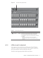
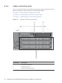
2.4.2
Cable connection ports
Figure 2-9 shows the location of the cable connection port of the crossbar box. See the
following chapters for the procedures for maintaining the cables:
■
Chapter 9 Maintaining the XSCF BB Control Cables
■
Chapter 10
Maintaining the XSCF DUAL Control Cables
■
Chapter 11
Maintaining the Crossbar Cables (Optical)
Figure 2-9
Locations of cable connection ports
(1)
(2)
(3)
20
Location number
Connection port
1
XSCF DUAL control port
2
XSCF BB control port
3
Crossbar cable connection port
Crossbar Box for Fujitsu M10/SPARC M10 Systems Service Manual ・ November 2014
Chapter 3
Types of Maintenance
This section describes the types of maintenance performed on the crossbar box.
■
Types of Maintenance Supported for the Crossbar Box
3.1
■
Active Maintenance
■
Inactive Maintenance
■
System-stopped Maintenance
Types of Maintenance Supported for
the Crossbar Box
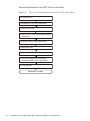
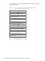
The types of maintenance supported for the crossbar box are divided into the
following three types depending on the system operation status: active maintenance,
inactive maintenance, and system-stopped maintenance.
■
Active maintenance
Maintenance is performed when the physical partition of an FRU requiring
maintenance is operating.
■
■
Inactive maintenance
Maintenance is performed when the physical partition of an FRU requiring
maintenance is stopped.
System-stopped maintenance
Maintenance is performed with all physical partitions stopped.
Each of the three maintenance types is further divided into two types: hot maintenance
and cold maintenance.
■
Hot maintenance
Maintenance is performed with the power cord of the crossbar box connected.
■
Cold maintenance
Maintenance is performed with the power cord of the crossbar box disconnected.
When you disconnect the power cord of the crossbar box, you also need to disconnect
all the power cords of the chassis including the physical partition. Therefore, to
21
perform cold maintenance in the building block configuration with the crossbar box,
only system-stopped/cold maintenance is enabled.
For example, to maintain an XSCF unit when even one physical partition is operating
(active state), dynamically release the XSCF unit from the system with the replacefru
command. At this time, maintain the XSCF unit with the power cord of the crossbar
box connected (hot). This is called active/hot maintenance of the XSCF unit.
Hot maintenance of the XSCF unit can be performed when the physical partition is
stopped (inactive or system stopped state). This is called inactive/hot maintenance or
system-stopped/hot maintenance of the XSCF unit. The status of the physical
partition does not affect the hot maintenance of the XSCF unit. Therefore, you do not
need to stop the physical partition to maintain the XSCF unit.
When you maintain the XSCF unit with the power cord of the crossbar box
disconnected (cold), you need to stop all physical partitions (system-stopped). This
maintenance is called system-stopped/cold maintenance of the XSCF unit.
When you perform maintenance on the chassis of the physical partition, see the case
of the building block configuration in "Table 7-2 List of available maintenance types
by FRU" in " Chapter 7 Maintenance Flow" of the Fujitsu M10-4/Fujitsu M10-4S/
SPARC M10-4/SPARC M10-4S Service Manual.
Note - For systems in the building block configuration with the crossbar box connected,
installation and removal work is enabled only for the target FRUs or the chassis of the
physical partition. To install or remove any FRU of the physical partition, see "Chapter 7
Maintenance Flow" in the Fujitsu M10-4/Fujitsu M10-4S/SPARC M10-4/SPARC M10-4S Service
Manual. When you install or remove the chassis of the physical partition, see "Chapter 8" or
subsequent sections in the SPARC M10 Systems Installation Guide.
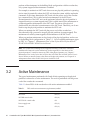
3.2
Active Maintenance
The type of maintenance performed with Oracle Solaris operating on the physical
partition is referred to as active maintenance. The work is performed with the power
cord of the crossbar box connected.
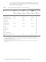
Table 3-1 shows FRUs of the crossbar box with active maintenance enabled.
Table 3-1
22
FRUs with active maintenance (replacement) enabled
FRU
Active/hot maintenance
XSCF unit
OK (*1)
XSCF BB control cable
OK (*2)
XSCF DUAL control cable
OK
Power supply unit
OK (*3)
Fan unit
OK (*3)
Crossbar Box for Fujitsu M10/SPARC M10 Systems Service Manual ・ November 2014
Table 3-1
FRUs with active maintenance (replacement) enabled (continue d)
FRU
Active/hot maintenance
Dedicated power distribution unit
OK
*1:
Maintenance is performed on the XSCF in the standby state or a slave XSCF. If the XSCF is operating as the
master XSCF, switch it to a standby XSCF.
*2: For maintenance on the XSCF BB control cable that connects the crossbar box and the chassis of the physical
partition, the chassis to connect to must be powered off. Therefore, when the physical partition consists of
one chassis, maintenance on the XSCF BB control cable that connects the crossbar box and the chassis of the
physical partition is not enabled in the active/hot state.
*3: This is supported only for a redundant configuration.
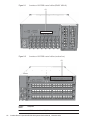
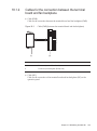
Figure 3-1
Active/hot maintenance
PPAR-ID#00
Solaris
Crossbar
box
SPARC M10-4S
XSCFU XSCFIF
XSCF
(BB-ID#80)
(BB-ID#00)
SPARC M10-4S
Crossbar
box
XSCF
XSCFU XSCFIF
(BB-ID#01)
(BB-ID#81)
..
.
Crossbar
box
PPAR-ID#08
Hot
Solaris
SPARC M10-4S
Cold
Active
XSCF
(BB-ID#08)
Stopped
: XSCF BB
control cables
..
.
: Crossbar cables
XSCFU XSCFIF
(BB-ID#82)
PPAR-ID#07
Solaris
SPARC M10-4S
Crossbar
box
PPAR-ID#15
Solaris
SPARC M10-4S
XSCFU XSCFIF
XSCF
XSCF
(BB-ID#83)
(BB-ID#07)
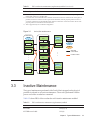
3.3
(BB-ID#15)
Inactive Maintenance
The type of maintenance performed with Oracle Solaris stopped on the physical
partition is referred to as inactive maintenance. The work is performed with the
power cord of the crossbar box connected.
Table 3-2 shows FRUs of the crossbar box with inactive maintenance enabled.
Table 3-2
FRUs with inactive maintenance (replacement) enabled
FRU
Inactive/hot maintenance
XSCF unit
OK (*1) (*4)
XSCF BB control cable
OK (*2)
Chapter 3
Types of Maintenance
23
Table 3-2
FRUs with inactive maintenance (replacement) enabled (continue d)
FRU
Inactive/hot maintenance
XSCF DUAL control cable
OK (*4)
Crossbar cable
OK (*2)
Power supply unit
OK (*3) (*4)
Fan unit
OK (*3) (*4)
Dedicated power distribution unit
OK
*1:
Maintenance is performed on the XSCF in the standby state or a slave XSCF. If the XSCF is operating as the
master XSCF, switch it to a standby XSCF.
*2: For maintenance on the XSCF BB control cable that connects the crossbar box and the chassis of the physical
partition, the chassis to connect to must be powered off.
*3: This is supported only for a redundant configuration.
*4: When the physical partition is operating, you do not need to forcibly stop the physical partition.
Figure 3-2
PPAR-ID#00
Inactive/hot maintenance
Solaris
Crossbar
box
SPARC M10-4S
XSCFU XSCFIF
XSCF
(BB-ID#80)
(BB-ID#00)
SPARC M10-4S
Crossbar
box
XSCF
XSCFU XSCFIF
(BB-ID#01)
(BB-ID#81)
..
.
Crossbar
box
PPAR-ID#07
Solaris
SPARC M10-4S
PPAR-ID#08
Hot
Solaris
SPARC M10-4S
XSCF
Cold
Active
(BB-ID#08)
Stopped
..
.
: XSCF BB
control cables
: Crossbar cables
XSCFU XSCFIF
(BB-ID#82)
Crossbar
box
PPAR-ID#15
Solaris
SPARC M10-4S
XSCFU XSCFIF
XSCF
(BB-ID#07)
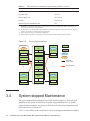
3.4
XSCF
(BB-ID#83)
(BB-ID#15)
System-stopped Maintenance
The type of maintenance performed with Oracle Solaris stopped on all the physical
partitions on the system is referred to as system-stopped maintenance. At systemstopped/cold maintenance, the power to all the chassis of the physical partitions and
the crossbar boxes is turned off.
Table 3-3 shows FRUs of the crossbar box with system-stopped maintenance enabled.
24
Crossbar Box for Fujitsu M10/SPARC M10 Systems Service Manual ・ November 2014
Table 3-3
FRUs for which system-stopped maintenance (replacement) is enabled
-: Maintenance cannot be performed.
FRU
System-stopped/hot
maintenance
System-stopped/cold
maintenance
XSCF unit
OK (*1)
OK
XSCF BB control cable
OK (*2)
OK
XSCF DUAL control cable
OK
OK
Crossbar cable
OK
OK
Crossbar unit
-
OK
Power supply unit
OK (*3)
OK
XSCF interface unit
-
OK
Fan unit
OK (*3)
OK
Fan backplane
-
OK
Operation panel
-
OK
Cable kit
-
OK
Crossbar backplane unit
-
OK
Dedicated power distribution unit
OK
OK
*1:
Maintenance is performed on the XSCF in the standby state or a slave XSCF. If the XSCF is operating as the
master XSCF, switch it to a standby XSCF.
*2: For maintenance on the XSCF BB control cable that connects the crossbar box and the chassis of the physical
partition, the chassis to connect to must be powered off.
*3: This is supported only for a redundant configuration.
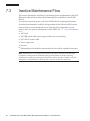
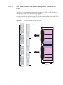
Figure 3-3
PPAR-ID#00
System-stopped/hot maintenance
Solaris
Crossbar
box
SPARC M10-4S
XSCFU XSCFIF
XSCF
(BB-ID#80)
(BB-ID#00)
SPARC M10-4S
Crossbar
box
XSCF
XSCFU XSCFIF
(BB-ID#01)
(BB-ID#81)
..
.
Crossbar
box
PPAR-ID#07
Solaris
SPARC M10-4S
PPAR-ID#08
Hot
Solaris
SPARC M10-4S
Cold
Active
XSCF
(BB-ID#08)
Stopped
: XSCF BB
control cables
..
.
: Crossbar cables
XSCFU XSCFIF
(BB-ID#82)
Crossbar
box
PPAR-ID#15
Solaris
SPARC M10-4S
XSCFU XSCFIF
XSCF
(BB-ID#07)
XSCF
(BB-ID#83)
(BB-ID#15)
Chapter 3
Types of Maintenance
25
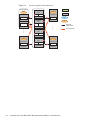
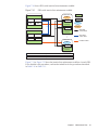
Figure 3-4
PPAR-ID#00
System-stopped/cold maintenance
Solaris
Crossbar
box
SPARC M10-4S
XSCFU XSCFIF
XSCF
(BB-ID#80)
(BB-ID#00)
SPARC M10-4S
Crossbar
box
XSCF
XSCFU XSCFIF
(BB-ID#01)
(BB-ID#81)
..
.
Crossbar
box
PPAR-ID#07
Solaris
SPARC M10-4S
PPAR-ID#08
SPARC M10-4S
XSCF
Crossbar
box
(BB-ID#07)
..
.
PPAR-ID#15
Solaris
SPARC M10-4S
26
XSCF
(BB-ID#83)
Active
Stopped
XSCFU XSCFIF
XSCF
Cold
(BB-ID#08)
XSCFU XSCFIF
(BB-ID#82)
Hot
Solaris
(BB-ID#15)
Crossbar Box for Fujitsu M10/SPARC M10 Systems Service Manual ・ November 2014
: XSCF BB
control cables
: Crossbar cables
Chapter 4
Preparation and Precautions for
Maintenance
This chapter describes preparations that must be completed prior to maintenance and
the precautions for various work and maintenance.
■
Confirming the System Configuration
4.1
■
Troubleshooting
■
Maintenance Precautions
Confirming the System Configuration
This section describes how to check the hardware and software configurations.
After completing any maintenance, it is necessary to confirm that the system
configuration is the same as that before starting the work. If an error occurs in the
system, record the system configuration and the FRU state before starting maintenance.
After maintenance, confirm that the system configuration is the same as that before
maintenance.
4.1.1
Confirming the hardware configuration
Execute the showhardconf command to confirm the configuration and the statuses of
FRUs mounted on the crossbar box and the chassis of the physical partition. Before
starting maintenance, confirm and record the hardware configuration of the crossbar
box and the chassis of the physical partition.
1. Log in to the XSCF shell.
2.
Execute the showhardconf command to confirm the hardware configuration
information.
XSCF> showhardconf
The following information is displayed:
Current configuration and status
■
27
4.1.2
■
Number of mounted Field Replaceable Units (FRUs)
■
Status of the unit in which a physical partition error or degradation occurred
■
Information on the PCI expansion unit
■
Name properties of the PCI Express (PCIe) card
Confirming the software and firmware
configurations
The software and firmware configurations and versions affect the operation of the
system. To change the configuration or investigate a problem, check the latest state
and check for any problems in the software.
Confirming the software configuration
Use Oracle Solaris commands to check the software configuration.
If you are logged in to the XSCF console, switch to the control domain console by
executing the console command beforehand.
Table 4-1 lists the commands used for checking the software configuration.
Table 4-1
Commands for checking the software configuration
Command
Description
pkg(1) (Oracle Solaris 11)
showrev(1M) (Oracle Solaris 10)
Displays Oracle Solaris correction information
and version.
ldm(1M)
Displays logical domain configuration information.
1.
For maintenance on physical partitions, log in to the control domain console
of the physical partition where the FRU requiring maintenance is mounted.
For details on logging in to the control domain console, see "8.3 Switching to
the Control Domain Console from the XSCF Shell" in the Fujitsu M10/SPARC
M10 Systems System Operation and Administration Guide.
2.
Execute the pkg(1) command to display Oracle Solaris correction information
and version.
- For Oracle Solaris 11, execute the pkg(1) command.
# pkg info entire
Name: entire
Summary: entire incorporation including Support Repository Update
(Oracle Solaris 11.1.12.5.0).
* SRU version
- For Oracle Solaris 10, execute the showrev(1M) command.
# showrev -p
28
Crossbar Box for Fujitsu M10/SPARC M10 Systems Service Manual ・ November 2014
To check the Oracle VM Server for SPARC version, execute the ldm(1M) command.
# ldm -V
Logical Domains Manager (v 3.1)
* Version of Oracle VM Server for SPARC
Hypervisor control protocol v 1.9
Using Hypervisor MD v 1.3
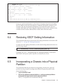
Confirming the firmware configuration
Confirm the firmware configuration with the version command, which is an XSCF
shell command.
1. Log in to the XSCF shell.
2.
Execute the version command to determine the firmware version information.
In the following example, "-c xcp" is entered to check the overall XCP version.
XSCF> version -c xcp
4.1.3
Confirming the FRU information and resource
information
Use XSCF shell commands to check the FRU information and resource information.
Table 4-2 lists the commands used for checking the FRU information and resource
information. For details on each command, see the Fujitsu M10/SPARC M10 Systems
XSCF Reference Manual of the XCP firmware version used.
Table 4-2
Commands for checking FRU information and resource information
Command
Description
showstatus
Displays the FRU status. Out of the FRUs in the system
configuration, this command displays information on a faulty or
degraded unit or FRU.
showboards
Displays information on a physical system board (PSB). Displays
information on a physical system board that belongs to the
specified physical partition and information on all the physical
system boards that are mounted.
showpcl
Displays the configuration information for a physical partition
(hardware resource information).
showfru
Displays the setting information for a device.
Chapter 4
Preparation and Precautions for Maintenance
29
4.2
Troubleshooting
This section describes the troubleshooting procedure.
In the following cases, which are suspected failure conditions, use the troubleshooting
flow to identify the failure location. For details on the troubleshooting flow, see "4.2.1
Determining the causes of failures."
■
When the CHECK LED is on
■
■
■
4.2.1
When an error message is displayed on the console
When an error is displayed as a result of executing a command for checking the
status
When an error is displayed in the error log
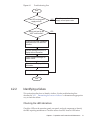
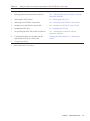
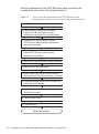
Determining the causes of failures
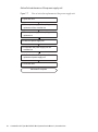
This section describes the flow for determining the causes of failures.
30
Crossbar Box for Fujitsu M10/SPARC M10 Systems Service Manual ・ November 2014
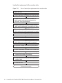
Figure 4-1
Troubleshooting flow
Start
YES
Is the LED on the power
supply unit off?
Check the connection of the power
supply unit and power cords.
NO
YES
Was e-mail sent by the
XSCF mail function?
NO
Confirm that an error message is
displayed on the OS and XSCF
consoles.
Execute showlogs on XSCF to
display failure information.
Check /var/adm/messages on
Oracle Solaris.
Write down the displayed failure
information.
Contact our service engineer.
End
4.2.2
Identifying a failure
This section describes how to identify a failure. Use the troubleshooting flow
described in "4.2.1 Determining the causes of failures" to determine an appropriate
way to check the failure.
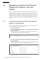
Checking the LED indications
Check the LEDs on the operation panel, rear panel, and each component to identify
the FRU requiring maintenance. Check the status of an FRU from its LED before
Chapter 4
Preparation and Precautions for Maintenance
31
starting maintenance work on the FRU.
■
Operation panel LEDs
You can determine the status of the system by checking the LEDs on the operation
panel. For details, see "2.3.1 Operation panel LEDs."
■
■
Rear panel LED
You can determine the status of the system by checking the CHECK LED on the
rear panel of the chassis, which duplicates the CHECK LED on the operation
panel. For details, see "2.3.2 LEDs on the rear panel (System locator)."
LED of each FRU
If an error occurs in the hardware in the chassis, you can determine the location of
the error by checking the LED of the FRU that incorporates the failed hardware.
For details, see "2.3.3 LEDs on each component."
Note that some FRUs, such as memory, do not have mounted LEDs. To check the
status of a FRU that does not have an LED, execute XSCF shell commands such as
the showhardconf command from the maintenance terminal. For details, see
"Checking the FRU status" below.
Checking error messages
Display error messages to check the log information and obtain an error overview.
You can use either of the following two methods to check the error messages:
■
Checking error log information using the XSCF shell
For details, see "12.1 Checking a Log Saved by the XSCF" in the Fujitsu
M10/SPARC M10 Systems System Operation and Administration Guide.
■
Checking messages with Oracle Solaris
For details, see "12.2 Checking Warning and Notification Messages" in the
Fujitsu M10/SPARC M10 Systems System Operation and Administration Guide.
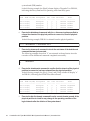
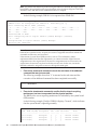
Checking the FRU status
Execute XSCF firmware commands to determine the system hardware configuration
and the status of each FRU.
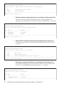
- showhardconf command
Execute the showhardconf command to check the information on the FRU list.
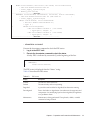
1. Log in to the XSCF shell.
2.
XSCF>
SPARC
+
+
32
Execute the showhardconf command to check the FRU list.
A faulty FRU is indicated by an asterisk (*) at the beginning of the line.
showhardconf
M10-4S;
Serial:2081230011; Operator_Panel_Switch:Locked;
System_Power:On; System_Phase:Cabinet Power On;
Partition#0 PPAR_Status:Powered Off;
Partition#1 PPAR_Status:Initialization Phase;
Crossbar Box for Fujitsu M10/SPARC M10 Systems Service Manual ・ November 2014
BB#00 Status:Normal; Role:Slave; Ver:2003h; Serial:2081231002;
+ FRU-Part-Number:CA07361-D202 A1
;
+ Power_Supply_System:Single;
+ Memory_Size:256 GB;
------------------------Omitted-----------------------XBBOX#80 Status:Normal; Role:Master; Ver:0101h; Serial:7867000297;
+ FRU-Part-Number:CA07361-D011 A0 /NOT-FIXD-01
;
+ Power_Supply_System:Single;
XBU#0 Status:Normal; Serial:PP0629L068
+ FRU-Part-Number:CA20393-B50X A2 ;
+ Type: A ;
*
CBL#L0 Status:Degraded;
+ FRU-Part-Number:2123628-2 ; Ver:3820h;
+ Type:Optic; Length: 3;
+ FRU-Part-Number:2123628-2 ; Ver:3820h;
+ Type:Optic; Length: 3;
------------------------Omitted----------------------
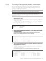
- showstatus command
Execute the showstatus command to check the FRU status.
1. Log in to the XSCF shell.
2.
Execute the showstatus command to check the status.
A faulty FRU is indicated by an asterisk (*) at the beginning of the line.
XSCF> showstatus
XBBOX#80;
*
PSU#0 Status:Faulted;
The FRU status is displayed after the "Status:" string.
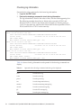
Table 4-3 describes the FRU status.
Table 4-3
FRU status
Display
Description
Normal
The unit is in the normal state.
Faulted
The unit is faulty and is not operating.
Degraded
A part of the unit has failed or degraded, but the unit is running.
Deconfigured
Due to the failure or degradation of another unit, the target unit and
components of its underlying layer has been degraded, though there
is no problem in them.
Maintenance
Maintenance is being performed. The replacefru, addfru, or initbb
command is being executed.
Chapter 4
Preparation and Precautions for Maintenance
33
Checking log information
Execute the showlogs command to check error log information.
1. Log in to the XSCF shell.
2.
Execute the showlogs command to check the log information.
The log information is listed in the order of date, with the oldest appearing first.
The following example shows that an Alarm status occurred in PSU#1 and
PSU#2 at 12:45:31 on Oct 20, the Alarm status changed to a Warning status at
15:45:31 on the same day, and then the Alarm status further expanded to PSU#1,
PSU#2, and PSU#3 at 17:45:31 on the same day.
XSCF> showlogs error
Date: Oct 20 12:45:31 JST 2012
Code: 00112233-445566778899aabbcc-8899aabbcceeff0011223344
Status: Alarm
Occurred: Oct 20 12:45:31.000 JST 2012
FRU: PSU#1,PSU#2
Msg: ACFAIL occurred (ACS=3)(FEP type = A1)
Date: Oct 20 15:45:31 JST 2012
Code: 00112233-445566778899aabbcc-8899aabbcceeff0011223344
Status: Warning
Occurred: Oct 20 15:45:31.000 JST 2012
FRU: PSU#1,PSU#2
Msg: ACFAIL occurred (ACS=3)(FEP type = A1)
Date: Oct 20 17:45:31 JST 2012
Code: 00112233-445566778899aabbcc-8899aabbcceeff0011223344
Status: Alarm
Occurred: Oct 20 17:45:31.000 JST 2012
FRU: PSU#1,PSU#2, PSU#3,*
Msg: ACFAIL occurred (ACS=3)(FEP type = A1)
Table 4-4 shows what log information each operand of the showlogs command can
display.
Table 4-4
34
Operands of the showlogs command and the log to be displayed
Operand
Description
error
Lists the error log.
event
Lists the event log.
power
Lists the power log.
env
Lists the temperature history.
monitor
Lists the monitoring message log.
console
Lists the console message log.
ipl
Lists the IPL message log.
panic
Lists the panic message log.
Crossbar Box for Fujitsu M10/SPARC M10 Systems Service Manual ・ November 2014
Checking the messages output by the predictive self-repairing
tool
Check the messages output from the Oracle Solaris Fault Manager predictive
self-repairing tool, running on Oracle Solaris. Oracle Solaris Fault Manager has the
following functions:
■
Receives telemetry information about errors.
■
Performs troubleshooting.
■
Disables the FRUs that have experienced errors.
■
Turns on the LED of an FRU that has experienced an error and displays the details
in a system console message.
Table 4-5 lists typical messages that are generated if an error occurs. These messages
indicate that the fault has already been diagnosed. If there are corrective actions that
can be taken by the system, they have already been taken. In addition, if the system is
running, corrective actions continue to be applied.
Messages are displayed on the console and are recorded in the /var/adm/messages
file.
Table 4-5
Predictive self-repairing messages
Output Displayed
Description
Nov 1 16:30:20 dt88-292 EVENT-TIME:Tue
Nov 1 16:30:20 PST 2005
EVENT-TIME: Time stamp of the
diagnosis
Nov 1 16:30:20 dt88-292 PLATFORM:
ORCL,SPARC64-X, CSN:-,HOSTNAME:dt88-292
PLATFORM: Description of the
chassis in which the error occurred
Nov 1 16:30:20 dt88-292 SOURCE:eft, REV:1.13
SOURCE: Information regarding
the diagnosis engine used to
identify the error
Nov 1 16:30:20 dt88-292 EVENT-ID:
afc7e660-d609-4b2f-86b8-ae7c6b8d50c4
EVENT-ID: Universally unique
event ID for this error
Nov 1 16:30:20 dt88-292 DESC:
Nov 1 16:30:20 dt88-292 A problem was detected in
the PCI Express subsystem
DESC: Basic description of the error
Nov 1 16:30:20 dt88-292 Refer to http://support.
oracle.com/msg/SUN4-8000-0Y for more information.
Website: Where to find specific
information and countermeasures
for this error
Nov 1 16:30:20 dt88-292 AUTO-RESPONSE:
One or more device instances may be disabled.
AUTO-RESPONSE: What the
system has done (if anything) to
alleviate any subsequent problems
Nov 1 16:30:20 dt88-292 IMPACT:Loss of services
provided by the device instances associated with this
fault.
IMPACT: Description of the
assumed impact of the failure
Chapter 4
Preparation and Precautions for Maintenance
35
Table 4-5
Predictive self-repairing messages (continued)
Output Displayed
Description
Nov 1 16:30:20 dt88-292 REC-ACTION:
Schedule a repair procedure to replace the affected
device. Use Nov 1 16:30:20 dt88-292 fmdump -v -u
EVENT_ID to identify the device or contact Sun for
support.
REC-ACTION: Brief description of
the corrective action the system
administrator should apply
Identifying the location of the chassis requiring maintenance
Execute the setlocator command to identify the location of the chassis requiring
maintenance by causing the CHECK LED on the operation panel and the CHECK
LED (locator) on the rear panel to blink.
1. Log in to the XSCF shell.
2.
Execute the setlocator command to blink the CHECK LED of the chassis
requiring maintenance, and determine its location.
The CHECK LEDs on the operation and rear panels blink.
The chassis requiring maintenance in the following execution example is the
master chassis. When specifying a different chassis such as BB#81, set "setlocator
-b 81 blink."
XSCF> setlocator -b 81 blink
For details on where to find and how to check the CHECK LEDs, see "2.3
Checking the LED Indications."
4.2.3
Downloading error log information
This section describes the operations for downloading error log information.
To download error log information, use the XSCF log fetch function. The XSCF unit
has a maintenance USB port so that maintenance information such as error logs can
be obtained easily. (The port is marked as MAINTENANCE on the rear panel.) For
details, see "12.1.15 Saving a log to a file with snapshot" and "12.1.16 Saving a log
to a local USB device" in the Fujitsu M10/SPARC M10 Systems System Operation and
Administration Guide.
In the following example, detailed information on the error logs of all chassis in the
system in a building block configuration is downloaded to the USB memory
connected to the USB port.
XSCF> snapshot –d usb0 –L F –r –a –v
Testing writability of USB device....SUCCESS
About to remove all files from device 'usb0'. Continue? [Y|N] : y
BB#00: start to execute snapshot
BB#01: start to execute snapshot
36
Crossbar Box for Fujitsu M10/SPARC M10 Systems Service Manual ・ November 2014
.
.
Collecting data into /media/usb_msd/<hostname>_<ipaddress>_<date>.zip
Data collection complete.
4.3
Maintenance Precautions
This section describes precautions for maintenance on the crossbar box.
When performing maintenance on the chassis of the physical partition, see "4.3
Maintenance Precautions" in the Fujitsu M10-4/Fujitsu M10-4S/SPARC M10-4/SPARC
M10-4S Service Manual.
4.3.1
Precautions for replacement
This section describes the precautions for replacement.
Precautions for XSCF unit replacement
■
■
■
■
Before replacing an XSCF unit, execute the dumpconfig command to save the
system setting information. When an XSCF unit is replaced, the CPU Activation
setting information and CPU Activation keys may be deleted. To restore the CPU
Activation setting information and CPU Activation keys that have been saved
with the dumpconfig command, execute the restoreconfig command.
For details, see "10.10 Saving/Restoring XSCF Setting Information" in the Fujitsu
M10/SPARC M10 Systems System Operation and Administration Guide.
If an XSCF unit is replaced, the system is started by the firmware version that is
applied to the replacement XSCF unit. If the firmware version is different from the
one that had been used before the replacement, it is automatically updated to that
version. However, this update takes time. To shorten the XSCF unit replacement
work time, we recommend removing the microSD card mounted in the XSCF unit
used before the replacement and mounting it in the XSCF unit to be used after the
replacement. Using the microSD card that had been used before the replacement
eliminates the need to update the firmware version to the one that had been used
before the replacement.
If you use the replacefru command to replace the XSCF unit, a completion
message appears when the incorporation of the XSCF unit into the crossbar box
completes. However, the activation of the replaced XSCF unit firmware may not
have completed by then. When you perform maintenance work on the XSCF unit,
perform the next operation ten or more minutes after the incorporation
completion message appears.
Do not replace the XSCF unit and the XSCF interface unit at the same time at
system-stopped/cold maintenance. If you replace both the XSCF unit and the
XSCF interface unit at the same time, the system will fail to operate normally.
Replace the XSCF unit in the hot state and then replace the XSCF interface unit in
Chapter 4
Preparation and Precautions for Maintenance
37
the cold state.
Precautions for crossbar cable replacement
■
Replace the crossbar cables in pairs.
■
Do not place heavy objects on the crossbar cables.
■
Do not bend the crossbar cables unduly. If you unduly bend a crossbar cable, it
may be damaged. Ensure that the bending radius of the crossbar cable is no less
than 35 mm (1.4 in.).
Precautions for power supply unit replacement
■
■
■
There are two power supply units. Thus, the system can continue operating even
if one of the units fails. Do not, however, operate the system for an extended
period while one unit has failed.
When replacing multiple power supply units, replace one unit at a time. If
redundancy of the power supply unit cannot be assured, then system-stopped
maintenance must be performed.
Do not force push the power supply unit into its slot. If excessive force is applied,
other components or the chassis may be damaged.
Precautions for fan unit replacement
■
■
The cooling fans have a redundant configuration. Thus, the system can continue
operating even if one of the fans in the fan units experiences a failure. Avoid
operating the system with a faulty fan for an extended period and replace the fan
unit containing the failed fan as soon as possible.
When replacing multiple fan units, replace one unit at a time. If a redundant
configuration cannot be assured, perform cold replacement.
Precautions for operation panel replacement
■
To replace the operation panel, set the BB-ID of the replacement operation panel to
the same value as that before replacement.
Precautions for replacement of dedicated power distribution unit
■
■
38
The crossbar box is connected to the two PDUs with power cords. Thus the system
can continue to operate even if one of the PDUs fails. Do not, however, operate the
system for an extended period while one unit has failed.
When replacing multiple dedicated power distribution units, replace one unit at a
time. If redundancy of the dedicated power distribution units cannot be
preserved, system-stopped maintenance must be performed.
Crossbar Box for Fujitsu M10/SPARC M10 Systems Service Manual ・ November 2014
4.3.2
Precautions for installation
The following describes precautions for installation.
■
Only the crossbar cable (optical) can be used for cables to connect the crossbar box
and the chassis of the physical partition.
■
■
■
■
4.3.3
Up to eight chassis of the physical partition can be installed for the two crossbar
box configuration, and up to 16 chassis of the physical partition can be installed
for the four-crossbar box configuration.
Only system-stopped/cold maintenance is enabled as a maintenance type for
installation from a two-crossbar box configuration to a four-crossbar box
configuration.
The crossbar box connection rule changes if crossbar boxes are installed from a
two-crossbar box configuration to a four-crossbar configuration. For crossbar box
expansion, see "Appendix B Cable Connection Information on Building Block
Configurations" in the Fujitsu M10/SPARC M10 Systems Installation Guide to
connect the crossbar cable.
For details on the procedure for installing a crossbar box, see "Chapter 8 Before
Installing/Removing a System with a Building Block Configuration" in the Fujitsu
M10/SPARC M10 Systems Installation Guide.
Precautions for removal
The following describes precautions for removal.
■
Use the initbb command to remove the chassis of the physical partition and the
crossbar box when crossbar boxes are removed for reduction from a four-crossbar
box configuration to a two-crossbar box configuration. If you remove them
without using the initbb command, the removed crossbar boxes and the removed
chassis of the physical partition cannot be used.
■
For details on the procedure for removing a crossbar box, see "Chapter 8 Before
Installing/Removing a System with a Building Block Configuration" in the Fujitsu
M10/SPARC M10 Systems Installation Guide.
Chapter 4
Preparation and Precautions for Maintenance
39
40
Crossbar Box for Fujitsu M10/SPARC M10 Systems Service Manual ・ November 2014
Chapter 5
Enabling the Removal of an FRU
Requiring Maintenance
This chapter describes the preparations that must be completed before you can
physically remove an FRU.
■
Preparing Tools Required for Maintenance
■
Releasing a Chassis of the Physical Partition to Connect to, from the System
■
Saving XSCF Setting Information
■
Releasing FRUs of the Crossbar Box from the System with the replacefru Command
■
Accessing an FRU
Caution - Do not operate a target Field Replaceable Unit (FRU) while OpenBoot
PROM is running (the ok prompt is displayed). After powering off the physical
partition or starting Oracle Solaris, operate the target FRU.
5.1
Preparing Tools Required for
Maintenance
This section describes the tools required for maintenance. Table 5-1 lists the tools
required for maintenance on a Field Replaceable Unit (FRU).
Table 5-1
Maintenance tools
Item
Use
Phillips screwdriver (No.2)
Removing or replacing screws
Flathead screwdriver (small)
Removing or replacing screws
Torx driver (T10)
Removing or replacing screws
Wrist strap
For static grounding
ESD mat
For static grounding
41
5.2
Releasing a Chassis of the Physical
Partition to Connect to, from the
System
To perform maintenance on the FRU connecting the crossbar box and the chassis of
the physical partition, the chassis of the physical partition to connect to must be
released from the system with the replacefru command. Perform this operation from
the logical domain. See "Chapter 7 Maintenance Flow" in the Fujitsu M10-4/Fujitsu
M10-4S/SPARC M10-4/SPARC M10-4S Service Manual to perform the necessary
operations according to the configuration of the physical partitions and the logical
domains.
5.2.1
Checking the operating condition of the physical
partition or logical domain
In the following execution example, the operating condition of the physical partition
and logical domain is checked from firmware.
1. Log in to the XSCF shell.
2.
Execute the showpparstatus command to confirm the operating condition of
the physical partition.
In the following example, [PPAR Status] of PPAR-ID 00 displays "Running",
which indicates that the physical partition is operating.
XSCF> showpparstatus -p 0
PPAR-ID
PPAR Status
00
Running
3.
Execute the showdomainstatus command to confirm the operating condition
of the logical domain.
In the following example, [Status] of the logical domains of PPAR-ID 00 displays
"Solaris running," which indicates that Oracle Solaris is operating.
XSCF> showdomainstatus
Logical Domain Name
primary
guest0
guest1
iodom0
iodom1
sdiodomain
sr-iodomain
42
-p 0
Status
Solaris
Solaris
Solaris
Solaris
Solaris
Solaris
Solaris
running
running
running
running
running
running
running
Crossbar Box for Fujitsu M10/SPARC M10 Systems Service Manual ・ November 2014
5.2.2
Enabling maintenance on the system
This section describes the procedure for enabling maintenance on a system with a
building block configuration with the crossbar box connected.
1. Switch the mode switches for the master chassis and those chassis whose
XSCFs are in the standby state to Service mode.
The BB-ID of the chassis with the mode switch to be switched is "80" and "81" in
a building block configuration with the crossbar box connected.
5.2.3
Releasing the chassis of the physical partition to
connect to, from the physical partition
This section describes the procedure for releasing a chassis of the physical partition
using dynamic reconfiguration (DR) for the physical partition.
Note - For the versions of XCP and Oracle VM Server for SPARC/SRU that support dynamic
reconfiguration (DR) of a physical partition, see the latest Product Notes.
Note - To add or remove an I/O device in the control domain, you need to first transition the
mode to delayed reconfiguration mode before adding or removing the I/O device. Then,
restart the control domain.
1.
Confirm that the I/O device in the chassis of the physical partition to connect
to is not used in the logical domain. (See "5.3 Checking the Operating
Condition and Resource Usage Status" and "5.4.1 Releasing the assignment of
I/O devices" in the Fujitsu M10-4/Fujitsu M10-4S/SPARC M10-4/SPARC M10-4S
Service Manual.)
2.
Log in to the XSCF shell.
3.
When the chassis of the physical partition to connect to is operating as the
master chassis, execute the switchscf command to switch the master XSCF
to a standby XSCF.
Enter "y" in response to the confirmation message.
If the chassis of the physical partition to connect to is the slave XSCF, go to step
5.
XSCF> switchscf -t Master
The XSCF unit switch between the Master and Standby states.
Continue? [y|n] :y
4.
Log in to the XSCF again.
5.
Execute the showboards command to confirm the status of the chassis of the
physical partition to connect to.
The BB-ID of the chassis of the physical partition to connect to is indicated as a
Chapter 5
Enabling the Removal of an FRU Requiring Maintenance
43
system board (PSB) number.
In the following example, the [Fault] column displays "Degraded" for PSB 00-0,
indicating that the system board is operating with some faulty parts.
XSCF> showboards -va
PSB PPAR-ID(LSB) Assignment
---- ------------ ----------00-0 00(00)
Assigned
01-0 00(01)
Assigned
02-0 00(02)
Assigned
03-0 00(03)
Assigned
6.
Pwr
---y
y
y
y
Conn
---y
y
y
y
Conf
---y
y
y
y
Test
------Passed
Passed
Passed
Passed
Fault
-------Degraded
Normal
Normal
Normal
Execute the deleteboard command with the -c disconnect option specified to
release the chassis of the physical partition to connect to, from the physical
partition.
In the following example, PSB 00-0 is released from the physical partition.
XSCF> deleteboard -c disconnect 00-0
7.
Execute the showresult command to check the end status of the deleteboard
command that was just executed.
The following example shows that "0" was returned as the end status since the
execution of the deleteboard command completed successfully.
XSCF> showresult
0
8.
Execute the showboards command to confirm that the chassis of the physical
partition to connect to has been released from the physical partition.
In the following example, the [Pwr], [Conn], and [Conf] columns all display "n"
for PSB 00-0, indicating that PSB 00-0 has been released.
XSCF> showboards -a
PSB PPAR-ID(LSB) Assignment
---- ------------ ----------00-0 00(00)
Assigned
01-0 00(01)
Assigned
02-0 00(02)
Assigned
03-0 00(03)
Assigned
9.
44
Pwr
---n
y
y
y
Conn
---n
y
y
y
Conf
---n
y
y
y
Test
------Passed
Passed
Passed
Passed
Fault
-------Degraded
Normal
Normal
Normal
Execute the ldm list-domain command from the control domain console of the
physical partition to check for any change in the operating condition of the
logical domain after the deletion of the system board.
Crossbar Box for Fujitsu M10/SPARC M10 Systems Service Manual ・ November 2014
5.2.4
Powering off the physical partition to connect to
This section describes the procedure for powering off the physical partition to
connect to. This applies if the system has a building block configuration and is
operating in multiple physical partitions.
Note - Before stopping the system, inform the users that the system will be stopped.
Note - When a physical partition is stopped by operating the XSCF command or the
operation panel, all the logical domains on the physical partition are stopped. Stop
applications as required.
1.
Log in to the XSCF shell.
2.
Execute the showpparstatus command to confirm the operating condition of
the physical partition.
In the following example, [PPAR STATUS] displays "Running" for PPAR-ID 00,
indicating that the physical partition is operating.
XSCF> showpparstatus -p 0
PPAR-ID
PPAR Status
00
Running
3.
Execute the showdomainstatus command to confirm the operating condition
of the logical domain.
In the following example, [Status] of the logical domain displays "Solaris
running", which indicates that Oracle Solaris is operating.
XSCF> showdomainstatus -p 0
Logical Domain Name
Status
primary
Solaris
4S-159-D0-G0
Solaris
4S-159-D0-G1
Solaris
4S-159-D0-G2
Solaris
4.
running
running
running
running
Execute the showboards command to confirm the status of the chassis of the
physical partition to connect to.
The BB-ID of the chassis of the physical partition to connect to is indicated as a
system board (PSB) number.
In the following example, we can see that [PPAR-ID] of PSB 00-0 is "00".
XSCF> showboards -a
PSB PPAR-ID(LSB) Assignment
---- ------------ ----------00-0 00(00)
Assigned
01-0 00(01)
Assigned
02-0 00(02)
Assigned
Chapter 5
Pwr
---y
y
y
Conn
---y
y
y
Conf
---y
y
y
Test
------Passed
Passed
Passed
Fault
-------Normal
Normal
Normal
Enabling the Removal of an FRU Requiring Maintenance
45
03-0 00(03)
5.
Assigned
y
y
y
Passed
Normal
Execute the poweroff command to stop all the logical domains on the
physical partition to connect to.
Enter "y" in response to the confirmation message.
XSCF> poweroff -p 0
PPAR-IDs to power off:00
Continue? [y|n] :y
00 : Powering off
*Note*
This command only issues the instruction to power-off.
The result of the instruction can be checked by the "showpparprogress".
6.
Execute the showpparstatus command to confirm that the power to the
physical partition is turned off.
In the following example, [PPAR Status] of PPAR-ID 00 displays "Powered Off",
which indicates that the power to the physical partition has been turned off.
XSCF> showpparstatus -p 0
PPAR-ID
PPAR Status
00
Powered Off
5.2.5
Stopping the entire system
This section describes the procedure for stopping the entire system. To undertake
system-stopped maintenance, power off all the physical partitions to stop the entire
system before physically removing any FRU.
Stop the system in either of the following two ways.
a) Stopping the system with the XSCF command
b) Stopping the system from the operation panel
Note - Before stopping the system, inform the users that the system will be stopped.
Note - When a physical partition is stopped by operating the XSCF command or the
operation panel, all the logical domains on the physical partition are stopped. Stop
applications as required.
46
1.
Stop the entire system.
For details, see "a) Stopping the system with the XSCF command" or "b)
Stopping the system from the operation panel."
2.
Execute the showpparstatus command to confirm that the power to the
physical partition is turned off.
In the following example, [PPAR Status] displays "Powered Off" for PPAR-IDs
Crossbar Box for Fujitsu M10/SPARC M10 Systems Service Manual ・ November 2014
00, 01, and 02, indicating that the power to all the physical partitions has been
turned off.
XSCF> showpparstatus -a
PPAR-ID
PPAR Status
00
Powered Off
01
Powered Off
02
Powered Off
3.
Execute the showdomainstatus command to confirm the operating condition
of the logical domain.
In the following example, [Status] of the logical domain displays "Solaris
powering down", which indicates that Oracle Solaris is shutting down.
XSCF> showdomainstatus -p 0
Logical Domain Name
Status
primary
Solaris
4S-159-D0-G0
Solaris
4S-159-D0-G1
Solaris
4S-159-D0-G2
Solaris
powering
powering
powering
powering
down
down
down
down
a) Stopping the system with the XSCF command
1.
Switch the mode switch on the operation panel to Service mode.
For details, see "2.2.2 Control function of the operation panel."
Note - For a building block configuration, switch the mode switches of the master chassis
and those chassis whose XSCFs are in the standby state.
2.
Log in to the XSCF shell.
3.
Execute the poweroff command.
Enter "y" in response to the confirmation message.
In the following example, the displayed status of PPAR-IDs 00, 01, and 02 is
"Powering off," so you can see that the power-off instruction for the physical
partition completed successfully.
XSCF> poweroff -a
PPAR-IDs to power off:00,01,02
Continue? [y|n] :y
00 : Powering off
01 : Powering off
02 : Powering off
The following processes are performed.
- Oracle Solaris is completely shut down.
Chapter 5
Enabling the Removal of an FRU Requiring Maintenance
47
- The system stops and enters the POWERON READY state (The XSCF is running).
For details, see "6.2.2 Stopping the whole system" in the Fujitsu M10/SPARC
M10 Systems System Operation and Administration Guide.
Note - The order in which guest domains shut down depends on the shut-down group
setting of Oracle VM Server for SPARC.
4.
Check that the POWER LED on the operation panel is off.
Note - For a building block configuration, check the POWER LEDs on all the chassis that
make up the system.
b) Stopping the system from the operation panel
1.
Switch the mode switch on the operation panel to Service mode.
For details, see "2.2.2 Control function of the operation panel."
Note - For a building block configuration, switch the mode switches of the master chassis
and those chassis whose XSCFs are in the standby state.
2.
Press the power switch on the operation panel for 4 seconds or more.
For details, see "2.2.2 Control function of the operation panel."
Note - For a building block configuration, press the power switch on the master chassis. The
power switches of the other chassis are disabled.
3.
Check that the POWER LED on the operation panel is off.
Note - For a building block configuration, check the POWER LEDs on all the chassis that
make up the system.
5.3
Saving XSCF Setting Information
This section describes how to save the following XSCF setting information:
Network configuration information, advanced setting information, guest domain
configuration information, etc.
■
■
CPU Activation key, CPU Activation assignment, etc.
■
PPAR operation mode, time zone setting, user information, etc.
The following example shows the command for saving the XSCF setting information
48
Crossbar Box for Fujitsu M10/SPARC M10 Systems Service Manual ・ November 2014
on the USB device. For details, see "10.10 Saving/Restoring XSCF Setting Information"
in the Fujitsu M10/SPARC M10 Systems System Operation and Administration Guide.
XSCF> dumpconfig -v -V file:///media/usb_msd/system.cfg
5.4
Releasing FRUs of the Crossbar Box
from the System with the replacefru
Command
The FRUs subject to the operation described here are as follows:
■
XSCF unit of the crossbar box
5.4.1
■
Power supply unit of the crossbar box
■
Fan unit of the crossbar box
■
SPARC M10-4S chassis
Releasing FRUs of the crossbar box with the
replacefru command
This section describes the procedure for releasing FRUs of the crossbar box, using the
XSCF unit of the crossbar box as an example.
For maintenance on the crossbar box of the master XSCF, execute the switchscf
command to change the crossbar box to the standby state, and then start maintenance.
1. Log in to the XSCF shell.
2.
When the crossbar box requiring maintenance is operating as the master
XSCF, execute the switchscf command to change the state to the standby
state, and then log in to the XSCF shell again.
When the crossbar box requiring maintenance is in the standby state or
operating as a slave XSCF, this step is not necessary.
3.
Execute the replacefru command to display the maintenance menu.
XSCF> replacefru
4.
Select the model requiring maintenance by specifying it with a numeric key.
Specify the chassis where the FRU requiring maintenance is mounted. In this
example, since maintenance is performed on the FRU of the crossbar box, "2" is
entered.
Chapter 5
Enabling the Removal of an FRU Requiring Maintenance
49
-----------------------------------------------------------------------------Maintenance/Replacement Menu
Please select a type of model which has FRU to be replaced.
1. BB
(4s Building Block Model)
2. XBBOX
(XB-BOX Model)
-----------------------------------------------------------------------------Select [1,2|c:cancel] :2
5.
Select the chassis requiring maintenance by specifying it with a numeric key.
Select the chassis that indicates an abnormal status. In this example, since
maintenance is performed on the XSCF unit mounted on XBBOX#80, "1" is entered.
-----------------------------------------------------------------------------Maintenance/Replacement Menu
Please select the chassis including replaced FRU.
No. FRU
Status
--- ------------------- -------------1 /XBBOX#80
Degraded
2 /XBBOX#81
Normal
-----------------------------------------------------------------------------Select [1-2|c:cancel] :1
6.
Select the FRU requiring maintenance by specifying it with a numeric key.
In the following example, since maintenance is performed on the XSCF unit, "3"
is entered.
-----------------------------------------------------------------------------Maintenance/Replacement Menu
Please select a type of FRU to be replaced.
1. FAN
(Fan Unit)
2. PSU
(Power Supply Unit)
3. XSCFU
(Extended System Control Facility Unit)
-----------------------------------------------------------------------------Select [1-3|c:cancel] :3
7.
Select the part requiring maintenance by specifying it with a numeric key.
For the FRU selected in step 6, each part status is shown. In this example, since
the XSCF unit on XBBOX#80 requires maintenance, "1" is entered.
-----------------------------------------------------------------------------Maintenance/Replacement Menu
Please select a FRU to be replaced.
No. FRU
Status
--- ------------------- -------------1 /XBBOX#80/XSCFU
Degraded
------------------------------------------------------------------------------
50
Crossbar Box for Fujitsu M10/SPARC M10 Systems Service Manual ・ November 2014
Select [1|b:back] :1
8.
After confirming that the selected FRU is displayed, enter "r".
You are about to replace XBBOX#80/XSCFU.
Do you want to continue?[r:replace|c:cancel] :r
9.
Confirm that the CHECK LEDs on the operation panel of the chassis requiring
maintenance and the system locater blink and the CHECK LED on the FRU
requiring maintenance is on or blinks.
For details on the locations of LEDs, see "2.3.2 LEDs on the rear panel (System
locator)" and "2.3.3 LEDs on each component."
Please execute the following steps:
1) Confirm the XSCF STANDBY LED of XBBOX#80/XSCFU is not lit.
2) Remove XBBOX#80/XSCFU.
3) After installing the exchanged device, please select [f:finish] :
Then, remove the FRU requiring maintenance. For the procedure for removing an
FRU, see the maintenance procedure on FRUs in Chapter 8 and later. Do not enter "f"
until you complete the maintenance work.
After replacing the FRU requiring maintenance to the crossbar box, enter "f" to start
restoring the crossbar box. For details, see "6.2.1 Restoring the crossbar box with the
replacefru command."
5.4.2
Releasing the FRU of the chassis of the physical
partition
This section describes the procedure for releasing the FRUs of the chassis of the
physical partition, using the chassis of the physical partition connected to the
crossbar box as an example.
Before releasing the FRUs of the chassis of the physical partition, enable maintenance
on the FRUs by stopping Oracle Solaris of the physical partition that the chassis
belongs to or by releasing the chassis to connect to from the physical partition. For
details, see "Figure 7-6 Active/cold replacement flow (building block configuration
only)" in the Fujitsu M10-4/Fujitsu M10-4S/SPARC M10-4/SPARC M10-4S Service
Manual.
1. Log in to the XSCF shell.
2.
Execute the replacefru command to display the maintenance menu.
XSCF> replacefru
3.
Select the model requiring maintenance by specifying it with a numeric key.
Specify the chassis where the FRU requiring maintenance is mounted. In this
Chapter 5
Enabling the Removal of an FRU Requiring Maintenance
51
example, since the physical partition chassis requires maintenance, "1" is entered.
-----------------------------------------------------------------------------Maintenance/Replacement Menu
Please select a type of model which has FRU to be replaced.
1. BB
(4s Building Block Model)
2. XBBOX
(XB-BOX Model)
-----------------------------------------------------------------------------Select [1,2|c:cancel] :1
4.
Select the chassis requiring maintenance by specifying it with a numeric key.
Select the chassis that indicates an abnormal status. In this example, since
maintenance is performed on BB#0 that indicates an abnormal status, "1" is
entered.
-----------------------------------------------------------------------------Maintenance/Replacement Menu
Please select the chassis including replaced FRU.
No. FRU
Status
--- ------------------- -------------1 /BB#0
Degraded
2 /BB#1
Normal
3 /BB#2
Normal
4 /BB#3
Normal
-----------------------------------------------------------------------------Select [1-4|c:cancel] :1
5.
Select the FRU requiring maintenance by specifying it with a numeric key.
In this example, since maintenance is performed with the chassis removed, "1" is
entered.
-----------------------------------------------------------------------------Maintenance/Replacement Menu
Please select the BB or a type of FRU to be replaced.
1. BB itself
2. FAN
(Fan Unit)
3. PSU
(Power Supply Unit)
-----------------------------------------------------------------------------Select [1-3|c:cancel] :1
6.
Select the part requiring maintenance by specifying it with a numeric key.
For the FRU selected in step 5, each part status is shown. In this example, since
the chassis of BB#0 is to be removed, "1" is entered.
-----------------------------------------------------------------------------Maintenance/Replacement Menu
Please select a FRU to be replaced.
52
Crossbar Box for Fujitsu M10/SPARC M10 Systems Service Manual ・ November 2014
No. FRU
Status
--- ------------------- -------------1 /BB#0
Degraded
-----------------------------------------------------------------------------Select [1|b:back] :1
7.
After confirming that the selected FRU is displayed, enter "r".
You are about to replace BB#0.
Do you want to continue?[r:replace|c:cancel] :r
8.
Confirm that the CHECK LEDs on the operation panel of the chassis requiring
maintenance and the system locater blink and the CHECK LED on the FRU
requiring maintenance is on or blinks.
For details on the locations of LEDs, see "2.3.2 LEDs on the rear panel (System
locator)" and "2.3 Checking the LED Indications."
Please execute the following steps:
1) Confirm the XSCF STANDBY LED of BB#0 is not lit.
2) Turn off the breaker of BB#0.
3) Remove BB#0.
4) Execute either the following:
4-1) After the exchanged device is connected with the system,
turn on the breaker of BB#0, and please select 'finish'.
4-2) If you want to suspend the maintenance without exchanging device,
please select 'cancel'.
[f:finish|c:cancel] :
Then, remove the FRU requiring maintenance. For the procedure for removing an
FRU, see the maintenance procedure on FRUs in Chapter 8 and later. Do not enter "f"
until you complete the maintenance work.
After replacing the chassis or the FRU requiring maintenance, enter "f" to start
restoring the chassis of the physical partition. For details, see "6.2.2 Restoring the
FRUs of the chassis of the physical Partition."
5.5
Accessing an FRU
This section describes the operations that must be completed before access to the FRU
requiring maintenance.
5.5.1
Removing the power cord
When removing the power cord of the chassis to perform maintenance work on an
Chapter 5
Enabling the Removal of an FRU Requiring Maintenance
53
FRU, do so only after removing the cable clamp from the power cord.
Removing the power cord of the crossbar box
1.
Release the latch (A in the figure) of the cable clamp.
Pulling the cable clamp toward the rear of the chassis facilitates the release of the
latch.
Figure 5-1
Releasing the cable clamp (crossbar box)
A
2.
Remove the power cord from the power supply unit on the rear of the chassis.
Figure 5-2
54
Removing the power cord (crossbar box)
Crossbar Box for Fujitsu M10/SPARC M10 Systems Service Manual ・ November 2014
Removing the power cord of the SPARC M10-4S
1.
Release the latch (A in the figure) of the cable clamp.
Pulling the cable clamp toward the rear of the chassis facilitates the release of the
latch.
Figure 5-3
Releasing the cable clamp (SPARC M10-4S)
A
2.
Remove the power cord from the PSU backplane unit on the rear of the
chassis.
Figure 5-4
Removing the power cord (SPARC M10-4S)
Chapter 5
Enabling the Removal of an FRU Requiring Maintenance
55
5.5.2
Removing the front cover
To perform maintenance on the following FRUs from the front of the crossbar box
chassis, remove the front cover before starting the work:
■
Fan unit
■
Fan backplane
■
Operation panel
1.
Release the right and left slide locks of the front cover and pull it towards the
front.
Figure 5-5
2.
56
Releasing the slide locks of the front cover
Lift the front cover upwards to remove it.
Crossbar Box for Fujitsu M10/SPARC M10 Systems Service Manual ・ November 2014
Chapter 6
Restoring the System
This chapter describes the procedures required to restore the system after FRU
maintenance. See this chapter, as required, when performing maintenance on each
FRU described in Chapter 8 onward.
■
Restoring the Chassis
■
6.1
Incorporating the FRUs of the Crossbar Box into the System with the replacefru
Command
■
Diagnosing the Crossbar Unit and Crossbar Cables
■
Restoring XSCF Setting Information
■
Incorporating a Chassis into a Physical Partition
■
Making the System Normal Operation State
■
Powering On the Physical Partition Requiring Maintenance
■
Starting the Entire System
Restoring the Chassis
This section describes operations required to restore the chassis.
6.1.1
Installing the power cord
If the power cord of the chassis was removed to perform the maintenance work,
connect the power cord and then attach the cable clamp to the power cord.
Installing the power cord of the crossbar box
1.
Connect a power cord to the power supply unit of the crossbar box.
57
Figure 6-1
2.
Installing the power cord (crossbar box)
Clip the cable clamp around the power cord and then fix the cable clamp.
The cable clamp is firmly fixed by locking the latch (A in the figure) and then
pushing the cable clamp toward the front of the chassis.
Figure 6-2
Locking the cable clamp (crossbar box)
A
Installing the power cord of the SPARC M10-4S
1.
58
Connect the power cord to the PSU backplane unit of the SPARC M10-4S.
Crossbar Box for Fujitsu M10/SPARC M10 Systems Service Manual ・ November 2014
Figure 6-3
2.
Installing the power cord (SPARC M10-4S)
Clip the cable clamp around the power cord and then fix the cable clamp.
The cable clamp is firmly fixed by locking the latch (A in the figure) and then
pushing the cable clamp toward the front of the chassis.
Figure 6-4
Locking the cable clamp (SPARC M10-4S)
A
6.1.2
Installing the front cover
If the front cover of the crossbar box was removed to perform maintenance, install it
after installing the FRU at the front of or inside the chassis.
1. To install the front cover, insert the tabs of the front cover into the notches at
the bottom front of the chassis.
Chapter 6
Restoring the System
59
Figure 6-5
Installing the front cover
Note - Check that the front cover is firmly attached and fixed.
6.2
Incorporating the FRUs of the
Crossbar Box into the System with the
replacefru Command
The FRUs subject to the operation described here are as follows:
XSCF unit of the crossbar box
■
60
■
Power supply unit of the crossbar box
■
Fan unit of the crossbar box
■
SPARC M10-4S chassis
Crossbar Box for Fujitsu M10/SPARC M10 Systems Service Manual ・ November 2014
6.2.1
Restoring the crossbar box with the replacefru
command
This section describes the procedure for restoring the crossbar box, using the XSCF
unit of the crossbar box as an example.
The following example shows the restoration procedure from the completion of the
installation of the new XSCF unit to the crossbar box, after the execution of the
operation up to step 9 in "5.4.1 Releasing FRUs of the crossbar box with the
replacefru command."
1. After installing the FRU requiring maintenance to the crossbar box, return to
the operation of the replacefru command of the XSCF firmware, and enter "f".
In the following example, "f" is entered after the XSCF unit is replaced.
Please execute the following steps:
1) Confirm the XSCF STANDBY LED of XBBOX#80/XSCFU is not lit.
2) Remove XBBOX#80/XSCFU.
3) After installing the exchanged device, please select [f:finish] :f
Incorporation of the replaced FRU into the crossbar box starts. Wait until the
incorporation completes.
A message like the one shown below appears at XSCF unit incorporation.
Waiting for XBBOX#80/XSCFU to enter install state.
[This operation may take up to 20 minute(s)]
(progress scale reported in seconds)
0..... 30..... 60..... 90..... 120..... 150..... 180..... 210.....
240..... 270..... 300..... 330..... 360..... 390. done
Waiting for XBBOX#80/XSCFU to enter ready state.
[This operation may take up to 45 minute(s)]
(progress scale reported in seconds)
0..... 30..... 60..... 90..... 120..... 150..... 180..... 210.....
240..... 270..... 300..... 330..... 360..... 390..... 420..... done
2.
Confirm that the replaced FRU is incorporated normally into the crossbar box,
and enter "f".
In the following example, normal incorporation of the XSCF unit into the
crossbar box is confirmed and "f" is entered.
-----------------------------------------------------------------------------Maintenance/Replacement Menu
Status of the replaced FRU.
FRU
Status
------------------- -------------Chapter 6
Restoring the System
61
/XBBOX#80/XSCFU
Normal
-----------------------------------------------------------------------------The replacement of XBBOX#80/XSCFU has completed normally.[f:finish] :f
Note - The completion message shown above appears when the incorporation of the XSCF
unit into the crossbar box completes. However, the activation of the replaced XSCF unit
firmware may not have completed by then. When you perform maintenance work on the
XSCF unit, enter "f" 10 or more minutes after the incorporation completion message shown
above appears.
3.
When the maintenance menu appears, enter "c" to exit the replacefru command.
-----------------------------------------------------------------------------Maintenance/Replacement Menu
Please select a type of model which has FRU to be replaced.
1. BB
(4s Building Block Model)
2. XBBOX
(XB-BOX Model)
-----------------------------------------------------------------------------Select [1,2|c:cancel] :c
6.2.2
Restoring the FRUs of the chassis of the physical
Partition
This section describes the procedure for restoring the FRUs of the physical partition,
using the operation for restoring the physical partition chassis to the building block
configuration as an example.
The following example shows the restoration procedure from the repair of the faulty
location and the steps up to the completion of physical connections such as those of
the XSCF BB control cable and crossbar cable, after the execution of the operation up
to step 8 in "5.4.2 Releasing the FRU of the chassis of the physical partition."
1. After installing the FRU requiring maintenance to the physical partition, return
to the operation of the replacefru command of the XSCF firmware, and enter
"f".
In the following example, the connection of the power cord to the physical
partition chassis and the start of blinking of the READY LED on the XSCF are
confirmed, and "f" is entered.
Please execute the following steps:
1) Confirm the XSCF STANDBY LED of BB#0 is not lit.
2) Turn off the breaker of BB#0.
3) Remove BB#0.
4) Execute either the following:
4-1) After the exchanged device is connected with the system,
turn on the breaker of BB#0, and please select 'finish'.
62
Crossbar Box for Fujitsu M10/SPARC M10 Systems Service Manual ・ November 2014
4-2) If you want to suspend the maintenance without exchanging device,
please select 'cancel'.
[f:finish|c:cancel] :f
Entering "f" displays the following screen. Wait until the processing has completed.
Waiting for BB#0 to enter install state.
[This operation may take up to 20 minute(s)]
(progress scale reported in seconds)
0..... 30..... 60..... 90..... 120..... 150..... 180..... 210.....
240..... 270..... 300..... 330..... 360..... done
Waiting for BB#0 to enter ready state.
[This operation may take up to 45 minute(s)]
(progress scale reported in seconds)
0..... 30..... 60..... 90..... 120..... 150..... 180..... 210.....
240..... 270..... 300..... done
2.
When the chassis of the physical partition is incorporated, the following
confirmation message appears. Enter "s".
Do you want to start to diagnose BB#0?[s:start|c:cancel] :
3.
The following confirmation message appears. Enter "y" to start the diagnosis.
Diagnostic tests for BB#0 have started.
Initial diagnosis is about to start, Continue?[y|n] :y
A screen like the one below appears. Wait until the processing has completed.
PSB#00-0 power on sequence started.
0..... 30..... 60..... 90.....120.....150.....180.....210.end
Initial diagnosis started. [7200sec]
0..... 30..... 60..... 90.....120.....150.....180.....210.....240.....|
270.....300.....330.....360.....390.....420.....450.....480.....510.....|
540.....570.....600.....630.....660.....690.....720.....750.....780.....\
810.....840.....870.....900.....930.end
Initial diagnosis has completed.
PSB power off sequence started. [1200sec]
0..... 30..... 60..... 90.end
PSB powered off.
PSB Test
Fault
---- ------- -------00-0 Passed Normal
done
4.
The diagnosis result appears when the diagnosis completes. Confirm that the
status is normal ("Normal"), and then enter "f".
Chapter 6
Restoring the System
63
-----------------------------------------------------------------------------Maintenance/Replacement Menu
Status of the replaced FRU.
FRU
Status
------------------- -------------/BB#0
Normal
-----------------------------------------------------------------------------The replacement of BB#0 has completed normally.[f:finish] :f
5.
Enter "c" to stop maintenance, and terminate the replacefru command.
-----------------------------------------------------------------------------Maintenance/Replacement Menu
Please select a type of model which has FRU to be replaced.
1. BB
(4s Building Block Model)
2. XBBOX
(XB-BOX Model)
-----------------------------------------------------------------------------Select [1,2|c:cancel] :c
6.3
Diagnosing the Crossbar Unit and
Crossbar Cables
This section shows an example of the command for diagnosing the crossbar unit
mounted in the physical partition chassis in a system with a building block
configuration. The command also diagnoses the crossbar cables in the chassis and
their connection status.
The following example shows the diagnosis of the crossbar cable between PPAR-ID 0
and BB-ID 1 and the crossbar unit.
The meanings of the specified options are as follows.
-b bb_id
Specify the BB-ID of the SPARC M10-4S chassis to start the diagnosis.
For the SPARC M10-4S (without crossbar box), an integer from 0 to 3 can be
specified as the bb_id. For the SPARC M10-4S (with crossbar box), an integer from
0 to 15 can be specified. This option can be specified with -t or -p.
-p ppar_id
Specify the PPAR-ID of the physical partition on which the SPARC M10-4S
chassis that is the communication destination is operating.
An integer from 0 to 15 can be specified as the ppar_id depending on the system
configuration.
64
Crossbar Box for Fujitsu M10/SPARC M10 Systems Service Manual ・ November 2014
XSCF> diagxbu -b 1 -p 0
XBU diagnosis is about to start, Continue?[y|n] :y
Power on sequence started. [7200sec]
0..... 30..... 60..... 90.....120end
XBU diagnosis started. [7200sec]
0..... 30..... 60..... 90.....120end
completed.
Power off sequence started. [1200sec]
0..... 30..... 60..... 90.....120end
completed.
*Note*
Please confirm the error of XBU by "showlogs error".
In addition, please confirm the degraded of XBU by "showstatus".
Even if you perform maintenance on the chassis of the physical partition (including
the CPU memory unit) with the replacefru command, the diagxbu command is not
executed. After physical partition maintenance work with the crossbar unit and
crossbar cables removed, use the diagxbu command to diagnose the condition of the
crossbar unit and crossbar cables and the crossbar cable connection status.
6.4
Restoring XSCF Setting Information
This section describes how to restore the XSCF setting information saved on the USB
device in "5.3 Saving XSCF Setting Information."
To restore the XSCF setting information, use the restoreconfig command as shown in
the following example.
XSCF> restoreconfig -V file:///media/usb_msd/system.cfg
For details, see "10.10 Saving/Restoring XSCF Setting Information" in the Fujitsu
M10/SPARC M10 Systems System Operation and Administration Guide.
6.5
Incorporating a Chassis into a Physical
Partition
This section describes the procedure for incorporating a chassis into a physical
partition by using dynamic reconfiguration (DR) for the physical partition after
chassis maintenance.
1. Log in to the XSCF shell.
2.
Execute the addboard command with the -c configure option specified to
incorporate the target chassis into the physical partition.
Enter "y" in response to the confirmation message.
Chapter 6
Restoring the System
65
Note - In system board (PSB) incorporation using the addboard command, the target system
board (PSB) is incorporated into the physical partition after a hardware diagnosis of the PSB.
Therefore, it may take time for the command execution to complete.
In the following example, PSB 00-0 is incorporated into PPAR-ID 0.
XSCF> addboard -c configure -p 0 00-0
PSB#00-0 will be configured into PPAR-ID 0. Continue?[y|n] :y
Start connecting PSB to PPAR. [3600sec]
0..... 30..... 60..... 90.....120.....150.....180.....210.....240.....\
270.....300.....330.....360.....390.....420.....450.....480.....510.....540.....570.....end
Connected PSB to PPAR.
Start configuring PSB to Logical Domains (LDoms) Manager. [1800sec]
0.....end
Configured PSB to Logical Domains (LDoms) Manager.
Operation has completed.
Note - If you execute the addboard command without specifying the -m option or with
bind=resource specified for the -m option, the resource assignment state before deleteboard
command execution may not be restored.
If the amount of system board (PSB) resources, such as CPUs and memory, before
replacement differs from that after replacement, you cannot restore the original resource
assignment state to the original state. If the resource assignment state is not restored to the
original state, the resources are placed in the free resource state. In this case, execute the
ldm(1M) command to assign the resources to the logical domain again.
3.
Execute the showresult command to check the end status of the addboard
command that was just executed.
The following example shows that "0" is returned as the end status and the
execution of the addboard command has been completed successfully.
XSCF> showresult
0
4.
Execute the showboards command to confirm that the chassis requiring
maintenance has been incorporated into the physical partition.
The BB-ID of the server requiring maintenance is indicated by the system board
(PSB) number.
In the following example, [Fault] of PSB 00-0 displays "Normal", which indicates
that the system board is operating normally.
XSCF> showboards -a
PSB PPAR-ID(LSB) Assignment
---- ------------ ----------00-0 00(00)
Assigned
01-0 00(01)
Assigned
02-0 00(02)
Assigned
66
Pwr
---y
y
y
Conn
---y
y
y
Conf
---y
y
y
Crossbar Box for Fujitsu M10/SPARC M10 Systems Service Manual ・ November 2014
Test
------Passed
Passed
Passed
Fault
-------Normal
Normal
Normal
03-0 00(03)
5.
Assigned
y
y
y
Passed
Normal
Execute the showstatus command to confirm that the FRU is operating
normally after the completion of maintenance.
Nothing is displayed if it is normal.
XSCF> showstatus
6.
Execute the showhardconf command to check the hardware configuration
and the status of each FRU.
Confirm that no asterisk (*) is displayed in front of any FRU.
XSCF> showhardconf
7.
If the state of the master chassis requiring maintenance has been switched to
the standby state before maintenance, execute the switchscf command to
switch the chassis to the master XSCF.
XSCF> switchscf -t Standby
8.
6.6
Restore the logical domain of the physical partition to its pre-maintenance
state.
For details, see "6.5.2 Incorporating an I/O device" and "6.5.3 Restoring the
logical domain to the pre-maintenance state" in the Fujitsu M10-4/Fujitsu
M10-4S/SPARC M10-4/SPARC M10-4S Service Manual.
Making the System Normal Operation
State
This section describes the procedure for enabling the normal operation state on a
system with a building block configuration with the crossbar box connected.
1. Switch the mode switches of the master chassis and those chassis whose
XSCFs are in the standby state to Locked mode.
The BB-ID of the chassis with the mode switch to be switched is "80" and "81" in
a building block configuration with the crossbar box connected.
Chapter 6
Restoring the System
67
6.7
Powering On the Physical Partition
Requiring Maintenance
This section describes the procedure for powering on a physical partition requiring
maintenance.
1. Switch the mode switches of the master chassis and those chassis
(BB-ID#00, #01) whose XSCFs are in the standby state to Locked mode.
2.
Log in to the XSCF shell.
3.
Execute the showstatus command to confirm that the FRU is operating
normally after the completion of maintenance.
Nothing is displayed if it is normal.
XSCF> showstatus
4.
Execute the showhardconf command to check the hardware configuration
and the status of each FRU.
XSCF> showhardconf
5.
If the state of the master chassis requiring maintenance has been switched to
the standby state before maintenance, execute the switchscf command to
switch the chassis to the master XSCF.
XSCF> switchscf -t Standby
6.
Execute the poweron command to power on the stopped physical partition.
In the following example, PPAR-ID 0 is specified.
XSCF> poweron -p 0
6.8
Starting the Entire System
This section describes the procedure for starting the entire system.
The system can be started in either of the following two ways:
Starting the system with an XSCF command
■
■
1.
68
Starting the system from the operation panel
Check that the XSCF STANDBY LED on the operation panel is on.
Crossbar Box for Fujitsu M10/SPARC M10 Systems Service Manual ・ November 2014
Note - For a building block configuration, check the XSCF STANDBY LEDs of all the chassis
constituting the system.
2.
Log in to the XSCF shell.
3.
Switch the mode switch on the operation panel to Locked mode.
Note - For a building block configuration, switch the mode switches of the master chassis
and those chassis whose XSCFs are in the standby state.
4.
Execute the showstatus command to confirm that there is no problem with
the FRU after the completion of maintenance.
If there is no problem, nothing is displayed.
XSCF> showstatus
5.
Execute the showhardconf command to check the hardware configuration
and the status of each FRU.
XSCF> showhardconf
For details, see "Checking the FRU status" in "Identifying a failure."
6.
Start the entire system.
For details, see "6.8.1 Starting the system with an XSCF command" or "6.8.2
Starting the system from the operation panel."
After a short while, the following processes are performed.
■
■
The POWER LED on the operation panel will be turned on.
The power-on self-test (POST; self diagnosis when powering on) will be
executed.
Then, the system starts up. For details, see "6.1 Starting the System" in the
Fujitsu M10/SPARC M10 Systems System Operation and Administration Guide.
6.8.1
Starting the system with an XSCF command
1.
Execute the poweron command.
Enter "y" in response to the confirmation message.
XSCF> poweron -a
PPAR-IDs to power on:00,01
Continue? [y|n] :y
00 : Powering on
01 : Powering on
Chapter 6
Restoring the System
69
6.8.2
Starting the system from the operation panel
1.
Press the power switch on the operation panel for 1 second or more (less
than 4 seconds).
For details, see "2.2.2 Control function of the operation panel."
Note - For a building block configuration, press the power switch on the master chassis. The
power switches of the other chassis are disabled.
70
Crossbar Box for Fujitsu M10/SPARC M10 Systems Service Manual ・ November 2014
Chapter 7
Maintenance Flow
This chapter describes the crossbar box maintenance workflow. See the maintenance
procedure for each FRU described in " Chapter 8" and later as required.
■
Maintenance Workflow and Type of Maintenance
■
Active Maintenance Flow
■
Inactive Maintenance Flow
■
System-stopped Maintenance Flow
71
7.1
Maintenance Workflow and Type of
Maintenance
Figure 7-1
Maintenance workflow in the building block configuration with the
crossbar box connected
(When replacing an FRU)
When maintaining FRU mounted in
chassis of physical partition
1. Identify FRU requiring
replacement
When maintaining crossbar box
2. Check available maintenance types
See "7.2 FRU Replacement Workflow" in
the Fujitsu M10-4/Fujitsu M10-4S/SPARC
M10-4/SPARC M10-4S Service Manual
3. Determine maintenance
type
4-a. Active replacement 4-b. Inactive replacement
72
4-c. System-stopped replacement
Crossbar Box for Fujitsu M10/SPARC M10 Systems Service Manual ・ November 2014
Table 7-1
Item
Maintenance workflow
Procedure
Reference
1
Identifying the FRU to be replaced
4.2.2
Identifying a failure
2
Checking the available maintenance
types
Table 7-2 Types of maintenance that can be
applied to each crossbar box FRU
3
Determining the maintenance types
(*1)
4
Replacing an FRU (*2)
4-a
Active replacement
7.2
Active Maintenance Flow
4-b
Inactive replacement
7.3
Inactive Maintenance Flow
4-c
System-stopped replacement
7.4
System-stopped Maintenance Flow
*1: The configuration of the system requiring maintenance and the FRU to be replaced may
affect system operation, such as in maintenance time and in stopping the logical domains.
Consult with the system administrator to decide the maintenance type to be used.
*2: FRUs mounted on the crossbar box can only be replaced but not installed or removed.
Note - For systems in the building block configuration with the crossbar box connected,
installation and removal work is enabled only for the target FRUs or the chassis of the
physical partition. To install or remove any FRU of the physical partition, see "Chapter 7
Maintenance Flow" in the Fujitsu M10-4/Fujitsu M10-4S/SPARC M10-4/SPARC M10-4S Service
Manual." When you install or remove the chassis of the physical partition, see "Chapter 8" or
subsequent sections in the SPARC M10 Systems Installation Guide.
Chapter 7
Maintenance Flow
73
Table 7-2 lists types of maintenance that can be applied to each crossbar box FRU.
Active maintenance and inactive maintenance are not enabled when the power is
disconnected or not being supplied.
Table 7-2
Types of maintenance that can be applied to each crossbar box FRU
-: Maintenance cannot be performed.
FRU
Active
Inactive
System
stopped
Hot
maintenance
Cold
maintenance
Hot
maintenance
Cold
maintenance
Hot
maintenance
Cold
maintenance
(*4)
XSCF unit
OK (*1)
-
OK (*1)
-
OK (*1)
OK
XSCF BB control cable
OK (*2)
-
OK (*2)
-
OK (*2)
OK
XSCF DUAL control cable
OK
-
OK
-
OK
OK
Crossbar cable
-
-
OK (*2)
-
OK
OK
Crossbar unit
-
-
-
-
-
OK
Power supply unit
OK (*3)
-
OK (*3)
-
OK (*3)
OK
XSCF interface unit
-
-
-
-
-
OK
Fan unit
OK (*3)
-
OK (*3)
-
OK (*3)
OK
Fan backplane
-
-
-
-
-
OK
Operation panel
-
-
-
-
-
OK
Cable kit
-
-
-
-
-
OK
Crossbar backplane unit
-
-
-
-
-
OK
Dedicated power distribution
unit
OK
-
OK
-
OK
OK
*1:
Maintenance is performed on the XSCF in the standby state or a slave XSCF. If the XSCF is operating as the master XSCF, switch it to
standby. To replace only the XSCF unit, active/hot maintenance is recommended where the physical partition does not stop.
*2: To maintain the XSCF BB control cable and crossbar cable that connect the crossbar box to the chassis of the physical partition, the
connected chassis must be powered off.
*3: Maintenance is supported only for a redundant configuration.
*4: Perform system-stopped/cold maintenance after all the physical partitions are stopped and the power cords of all the chassis are
disconnected.
74
Crossbar Box for Fujitsu M10/SPARC M10 Systems Service Manual ・ November 2014
7.2
Active Maintenance Flow
This section explains the replacement workflows in the active state for the following
FRUs mounted on the crossbar box.
■
XSCF unit
■
XSCF BB control cable
■
XSCF DUAL control cable
■
Power supply unit
■
Fan unit
■
Dedicated power distribution unit mounted on the rack for expanded connection
Note - Maintenance is not available in the active/cold state for FRUs mounted on the crossbar
box. In the active state, only hot maintenance is enabled.
Note - Active/hot maintenance is enabled for XSCF BB control cable used in either of the
following connections.
- Cable connecting crossbar boxes to each other
- Cable connecting each chassis to the crossbar box in a configuration where one physical
partition consists of multiple chassis
Figure 7-2 shows FRUs with active/hot maintenance enabled.
Figure 7-2
FRUs with active/hot maintenance enabled
PPAR-ID#00
Crossbar box (BB-ID#80)
OK
XSCFU
OK
Hot
Solaris
PSU
XSCFIF
OK
Cold
OK
XSCF
NG
FAN
OK
OK
SPARC M10-4S
(BB-ID#00)
Active
Stopped
OK
XSCF
Crossbar box (BB-ID#81)
OK
XSCFU
OK
PSU
XSCFIF
OK
FAN
SPARC M10-4S
(BB-ID#01)
: XSCF BB
control cables
..
.
: XSCF DUAL
control cables
PPAR-ID#07
NG
: Crossbar cables
Solaris
NG
XSCF
SPARC M10-4S
(BB-ID#07)
OK
Dedicated power distribution unit
OK
Dedicated power distribution unit
Figure 7-3 to Figure 7-9 show the active/hot replacement workflow for each FRU. For
Chapter 7
Maintenance Flow
75
a detailed work procedure, confirm the references for the procedures described in
Table 7-3 to Table 7-9. Also, for details on the connection routes of the XSCF BB
control cable, XSCF DUAL control table, and crossbar cable, see "Appendix B Cable
Connection Information on Building Block Configurations" in the Fujitsu M10/SPARC
M10 Systems Installation Guide.
Active/hot replacement of the XSCF unit
Figure 7-3
Flow of active/hot replacement of the XSCF unit
1. Open rack door
2. Release XSCF unit requiring replacement
from crossbar box
3. Remove XSCF unit requiring replacement
4. Switch microSD card
5. Install new XSCF unit
6. Incorporate new XSCF unit into crossbar box
7. Confirm that there is no problem with
replacement XSCF unit
8. Close rack door
Maintenance complete
76
Crossbar Box for Fujitsu M10/SPARC M10 Systems Service Manual ・ November 2014
Table 7-3
Active/hot replacement work procedure for the XSCF unit
Item
Work procedure
1
Opening the rack door
2
Releasing the XSCF unit requiring replacement from
the crossbar box
5.4.1 Releasing FRUs of the crossbar box with the
replacefru command
3
Removing the XSCF unit requiring replacement
8.3
Removing the XSCF Unit
4
Switching the microSD card
(can be omitted if the microSD card is not switched)
8.4
Switching the microSD Card
5
Installing a new XSCF unit
8.5
Installing the XSCF Unit
6
Incorporating a new XSCF unit into the crossbar box
6.2.1 Restoring the crossbar box with the
replacefru command
7
Confirming that there is no problem with the
replacement XSCF unit
Checking the FRU status in "4.2.2
failure"
8
Closing the rack door
Reference
Chapter 7
Identifying a
Maintenance Flow
77
Active/hot replacement of the XSCF DUAL control cable
Figure 7-4
Flow of active/hot replacement of the XSCF DUAL control cable
1. Open rack door
2. Release XSCF unit from crossbar box
3. Remove XSCF unit
4. Remove XSCF DUAL control cable requiring
replacement
5. Install new XSCF DUAL control cable
6. Install XSCF unit
7. Incorporate XSCF unit into crossbar box
8. Confirm that there is no problem with
replacement XSCF DUAL control cable
9. Close rack door
Maintenance complete
78
Crossbar Box for Fujitsu M10/SPARC M10 Systems Service Manual ・ November 2014
Table 7-4
Work procedure for active/hot replacement of the XSCF DUAL control cable
Item
Work procedure
1
Opening the rack door
2
Releasing the XSCF unit from the crossbar box
5.4.1 Releasing FRUs of the crossbar box with the
replacefru command
3
Removing the XSCF unit (*1)
8.3
4
Removing an XSCF DUAL control cable
10.2
Removing an XSCF DUAL Control Cable
5
Installing a new XSCF DUAL control cable
10.3
Installing an XSCF DUAL Control Cable
6
Installing the XSCF unit
8.5
7
Incorporating the XSCF unit into the crossbar box
6.2.1 Restoring the crossbar box with the
replacefru command
8
Confirming that there is no problem with the
replacement XSCF DUAL control cable
Checking the FRU status in "4.2.2
failure"
9
*1:
Reference
Removing the XSCF Unit
Installing the XSCF Unit
Identifying a
Closing the rack door
When you replace an XSCF DUAL control cable, you need to remove and then install the XSCF unit (pseudo replacement). Here,
partially pull the XSCF unit out halfway.
Chapter 7
Maintenance Flow
79
Active/hot replacement of the XSCF BB control cable (connecting crossbar
boxes to each other)
Figure 7-5
Flow of active/hot replacement of the XSCF BB control cable
(connecting crossbar boxes to each other)
1. Open rack door
2. Release XSCF unit from crossbar box
3. Remove XSCF unit
4. Remove XSCF BB control cable requiring
replacement
5. Install new XSCF BB control cable
6. Install XSCF unit
7. Incorporate XSCF unit into crossbar box
8. Confirm that there is no problem with
replacement XSCF BB control cable
9. Close rack door
Maintenance complete
80
Crossbar Box for Fujitsu M10/SPARC M10 Systems Service Manual ・ November 2014
Table 7-5
Work procedure for active/hot replacement of the XSCF BB control cable (connecting crossbar
boxes with each other)
Item
Work procedure
1
Opening the rack door
2
Releasing the XSCF unit from the crossbar box
5.4.1 Releasing FRUs of the crossbar box with the
replacefru command
3
Removing the XSCF unit (*1)
8.3
Removing the XSCF Unit
4
Removing the XSCF BB control cable requiring
replacement
9.2
Removing an XSCF BB Control Cable
5
Installing a new XSCF BB control cable
9.3
Installing an XSCF BB Control Cable
6
Installing the XSCF unit
8.5
Installing the XSCF Unit
7
Incorporating the XSCF unit into the crossbar box
6.2.1 Restoring the crossbar box with the
replacefru command
8
Confirming that there is no problem with the
replacement XSCF BB control cable
Checking the FRU status in "4.2.2
failure"
9
*1:
Reference
Identifying a
Closing the rack door
When you replace an XSCF BB control cable, you need to remove and then install the XSCF unit (pseudo replacement). Here,
partially pull the XSCF unit out halfway.
Chapter 7
Maintenance Flow
81
Active/hot replacement of the XSCF BB control cable (connecting the
crossbar box to the chassis of the physical partition)
Figure 7-6
Flow of active/hot replacement of the XSCF BB control cable
(connecting the crossbar box to the chassis of the physical partition)
1. Open rack door
2. Enable removal of SPARC M10-4S chassis,
to which XSCF BB control cable requiring
replacement is connected, from physical partition
3. Release SPARC M10-4S chassis, to which
XSCF BB control cable requiring replacement is
connected, from system
4. Remove all power cords of SPARC M10-4S chassis
to which XSCF BB control cable requiring
replacement is connected
5. Remove XSCF BB control cable requiring replacement
6. Install new XSCF BB control cable
7. Install all power cords of SPARC M10-4S chassis to
which replacement XSCF BB control cable is connected
8. Incorporate released SPARC M10-4S chassis into
system and physical partition
9. Confirm that there is no problem with replacement
XSCF BB control cable
10. Restore logical domain
11. Close rack door
Maintenance complete
82
Crossbar Box for Fujitsu M10/SPARC M10 Systems Service Manual ・ November 2014
Table 7-6
Work procedure for the active/hot replacement of the XSCF BB control cable (connecting the
crossbar box to the chassis of the physical partition)
Item
Work procedure
1
Opening the rack door
2
Enabling the removal of the SPARC M10-4S chassis,
to which the XSCF BB control cable requiring
replacement is connected, from the physical partition
Fujitsu M10-4/Fujitsu M10-4S/SPARC M10-4/SPARC
M10-4S Service Manual
5.3.1 Checking the operating condition of the
physical partition or logical domain
5.3.2 Checking the assignment status of I/O devices
5.4.1 Releasing the assignment of I/O devices
5.4.3 Releasing a chassis requiring maintenance
from the physical partition
3
Releasing the SPARC M10-4S chassis, to which the
XSCF BB control cable requiring replacement is
connected, from the system
Fujitsu M10-4/Fujitsu M10-4S/SPARC M10-4/SPARC
M10-4S Service Manual
5.8.1 Releasing of the SPARC M10-4S chassis
(possible only in a system with a building block
configuration)
4
Removing all the power cords of the SPARC M10-4S
chassis to which the XSCF BB control cable requiring
replacement is connected
Removing the power cord of the SPARC M10-4S in
"5.5.1 Removing the power cord"
5
Removing the XSCF BB control cable requiring
replacement
9.2
Removing an XSCF BB Control Cable
6
Installing a new XSCF BB control cable
9.3
Installing an XSCF BB Control Cable
7
Installing all the power cords of the SPARC M10-4S
chassis to which the replacement XSCF BB control
cable is connected
Installing the power cord of the SPARC M10-4S in
"6.1.1 Installing the power cord"
8
Incorporating the released SPARC M10-4S chassis
into the system and the physical partition
Fujitsu M10-4/Fujitsu M10-4S/SPARC M10-4/SPARC
M10-4S Service Manual
6.2.1 Incorporation of the SPARC M10-4S chassis
(possible only in a system with a building block
configuration)
6.5.1 Incorporating a Chassis into a Physical
Partition
9
Confirming that there is no problem with the
replacement XSCF BB control cable
Checking the FRU status in "4.2.2
failure"
10
Restoring the logical domain
Fujitsu M10-4/Fujitsu M10-4S/SPARC M10-4/SPARC
M10-4S Service Manual
6.5.3 Restoring the logical domain to the
pre-maintenance state
11
Closing the rack door
Reference
Chapter 7
Identifying a
Maintenance Flow
83
Active/hot maintenance of the power supply unit
Figure 7-7
Flow of active/hot replacement of the power supply unit
1. Open rack door
2. Release power supply unit requiring
replacement from crossbar box
3. Remove power supply unit requiring
replacement
4. Install new power supply unit
5. Incorporate new power supply unit into
crossbar box
6. Confirm that there is no problem with
replacement power supply unit
7. Close rack door
Maintenance complete
84
Crossbar Box for Fujitsu M10/SPARC M10 Systems Service Manual ・ November 2014
Table 7-7
Work procedure for the active/hot maintenance of the power supply unit
Item
Work procedure
1
Opening the rack door
2
Releasing the power supply unit requiring
replacement from the crossbar box
5.4.1 Releasing FRUs of the crossbar box with the
replacefru command
3
Removing the power supply unit requiring
replacement
13.2
Removing a Power Supply Unit
4
Installing a new power supply unit
13.3
Installing a Power Supply Unit
5
Incorporating a new power supply unit into the
crossbar box.
6.2.1 Restoring the crossbar box with the
replacefru command
6
Confirming that there is no problem with the
replacement power supply unit
Checking the FRU status in "4.2.2
failure"
7
Closing the rack door
Reference
Chapter 7
Identifying a
Maintenance Flow
85
Active/hot replacement of the fan unit
Figure 7-8
Flow of active/hot replacement of the fan unit
1. Open rack door
2. Release fan unit requiring replacement from
crossbar box
3. Remove fan unit requiring replacement
4. Install new fan unit
5. Incorporate new fan unit into crossbar box
6. Confirm that there is no problem with
replacement fan unit
7. Close rack door
Maintenance complete
86
Crossbar Box for Fujitsu M10/SPARC M10 Systems Service Manual ・ November 2014
Table 7-8
Work procedure for active/hot replacement of the fan unit
Item
Work procedure
1
Opening the rack door
2
Releasing the fan unit requiring replacement from
the crossbar box
5.4.1 Releasing FRUs of the crossbar box with the
replacefru command
3
Removing the fan unit requiring replacement.
15.2
Removing a Fan Unit
4
Installing a new fan unit
15.3
Installing a Fan Unit
5
Incorporating the new fan unit into the crossbar box
6.2.1 Restoring the crossbar box with the
replacefru command
6
Confirming that there is no problem with the
replacement fan unit
Checking the FRU status in "4.2.2
failure"
7
Closing the rack door
Reference
Chapter 7
Identifying a
Maintenance Flow
87
Active/hot replacement of the dedicated power distribution unit
Figure 7-9
Flow of active/hot replacement of the dedicated power distribution
unit
1. Open rack door
2. Remove dedicated power distribution unit
requiring replacement from rack
3. Install new dedicated power distribution unit
in rack
4. Close rack door
Maintenance complete
88
Crossbar Box for Fujitsu M10/SPARC M10 Systems Service Manual ・ November 2014
Table 7-9
Work procedure for the active/hot replacement of the dedicated power distribution unit
Item
Work procedure
1
Opening the rack door
2
Removing the dedicated power distribution unit
requiring replacement from the rack.
20.2 Removing the Dedicated Power Distribution
Unit
3
Installing a new dedicated power distribution unit in
the rack
20.3 Installing the Dedicated Power Distribution
Unit
4
Closing the rack door
Reference
Chapter 7
Maintenance Flow
89
7.3
Inactive Maintenance Flow
This section describes the workflow for performing inactive replacement of the XSCF
BB control cable and the crossbar cable connecting the crossbar box to the SPARC
M10-4S.
You need to remove the power cord of the SPARC M10-4S requiring maintenance.
Note that the maintenance workflow and procedure for the following FRUs are the
same as those for active maintenance even when the physical partition is in the
inactive state. For inactive maintenance on these FRUs, see "7.2 Active Maintenance
Flow."
■
XSCF unit
■
XSCF BB control cable (connecting crossbar boxes to each other)
■
XSCF DUAL control cable
■
Power supply unit
■
Fan unit
■
Dedicated power distribution unit mounted on the rack for expanded connection
Note - Maintenance is not available in the inactive/cold state for the FRUs mounted on the
crossbar box. During inactive maintenance, the physical partition of an FRU requiring
maintenance is stopped, but other physical partitions may be operating. Therefore, only hot
maintenance can be performed with the power cord of the crossbar box connected.
90
Crossbar Box for Fujitsu M10/SPARC M10 Systems Service Manual ・ November 2014
Figure 7-10 shows FRUs with inactive/hot maintenance enabled.
Figure 7-10
FRUs with inactive/hot maintenance enabled
PPAR-ID#00
Crossbar box (BB-ID#80)
OK
XSCFU
OK
Hot
Solaris
PSU
XSCFIF
OK
Cold
OK
XSCF
OK
FAN
OK
OK
SPARC M10-4S
(BB-ID#00)
Active
Stopped
OK
XSCF
Crossbar box (BB-ID#81)
OK
XSCFU
OK
PSU
XSCFIF
OK
FAN
SPARC M10-4S
(BB-ID#01)
: XSCF BB
control cables
..
.
: XSCF DUAL
control cables
PPAR-ID#07
NG
: Crossbar cables
Solaris
NG
XSCF
SPARC M10-4S
(BB-ID#07)
OK
Dedicated power distribution unit
OK
Dedicated power distribution unit
Figure 7-11 to Figure 7-12 show the inactive/hot replacement workflow for each FRU.
For a detailed work procedure, confirm the references for the procedures described
in Table 7-10 to Table 7-11.
Chapter 7
Maintenance Flow
91
Inactive/hot replacement of the XSCF BB control cable (connecting the
crossbar box to the physical partition)
Figure 7-11
Flow of inactive/hot replacement of the XSCF BB control cable
(connecting the crossbar box to the physical partition)
1. Open rack door
2. Switch mode switch of crossbar box to Service mode
3. Enable removal of SPARC M10-4S chassis, to
which XSCF BB control cable requiring replacement
is connected, from physical partition
4. Release SPARC M10-4S chassis, to which
XSCF BB control cable requiring replacement is
connected, from system
5. Remove all power cords of SPARC M10-4S chassis
to which XSCF BB control cable requiring
replacement is connected
6. Remove XSCF BB control cable requiring replacement
7. Install new XSCF BB control cable
8. Install all power cords of SPARC M10-4S chassis to
which replacement XSCF BB control cable is connected
9. Incorporate released chassis into physical partition
10. Switch mode switch of crossbar box to Locked mode
11. Activate physical partition to which chassis with
replacement XSCF BB control cable belongs
12. Confirm that there is no problem with replacement
XSCF BB control cable
13. Close rack door
Maintenance complete
92
Crossbar Box for Fujitsu M10/SPARC M10 Systems Service Manual ・ November 2014
Table 7-10
Work procedure for inactive/hot replacement of the XSCF BB control cable (connecting the
crossbar box to the physical partition)
Item
Work procedure
1
Opening the rack door
2
Switching the mode switch of the crossbar box to
Service mode
5.2.2
3
Enabling the removal of the SPARC M10-4S chassis,
to which the XSCF BB control cable requiring
replacement is connected, from the physical partition
Fujitsu M10-4/Fujitsu M10-4S/SPARC M10-4/SPARC
M10-4S Service Manual
5.3.1 Checking the operating condition of the
physical partition or logical domain
5.3.2 Checking the assignment status of I/O devices
5.4.1 Releasing the assignment of I/O devices
5.4.3 Releasing a chassis requiring maintenance
from the physical partition
4
Releasing the SPARC M10-4S chassis, to which the
XSCF BB control cable requiring replacement is
connected, from the system
Fujitsu M10-4/Fujitsu M10-4S/SPARC M10-4/SPARC
M10-4S Service Manual
5.8.1 Releasing of the SPARC M10-4S chassis
(possible only in a system with a building block
configuration)
5
Removing all the power cords of the SPARC M10-4S
chassis to which the XSCF BB control cable requiring
replacement is connected
Removing the power cord of the SPARC M10-4S in
"5.5.1 Removing the power cord"
6
Removing the XSCF BB control cable requiring
replacement
9.2
Removing an XSCF BB Control Cable
7
Installing a new XSCF BB control cable
9.3
Installing an XSCF BB Control Cable
8
Installing all the power cords of the SPARC M10-4S
chassis to which the replacement XSCF BB control
cable is connected
Installing the power cord of the SPARC M10-4S in
"6.1.1 Installing the power cord"
9
Incorporating a chassis into a released physical
partition
6.2.2 Restoring the FRUs of the chassis of the
physical Partition
10
Switching the mode switch of the crossbar box to
Locked mode
6.6
11
Activating the physical partition to which the chassis
with the XSCF BB control cable requiring replacement
belongs.
6.7 Powering On the Physical Partition Requiring
Maintenance
12
Confirming that there is no problem with the
replacement XSCF BB control cable
Checking the FRU status in "4.2.2
failure"
13
Closing the rack door
Reference
Enabling maintenance on the system
Making the System Normal Operation State
Chapter 7
Identifying a
Maintenance Flow
93
Inactive/hot replacement of the crossbar cable
Figure 7-12
Flow of inactive/hot replacement of the crossbar cable
1. Open rack door
2. Switch mode switch of crossbar box to Service mode
3. Enable removal of SPARC M10-4S chassis, to
which crossbar cable requiring replacement is
connected, from physical partition
4. Release SPARC M10-4S chassis, to which crossbar
cable requiring replacement is connected, from system
5. Remove all power cords of SPARC M10-4S chassis to
which crossbar cable requiring replacement is connected
6. Remove crossbar cable requiring replacement
7. Install new crossbar cable
8. Install all power cords of SPARC M10-4S chassis to
which replacement crossbar cable is connected
9. Incorporate released chassis into physical partition
10. Switch mode switch of crossbar box to Locked mode
11. Activate physical partition to which chassis with
replacement crossbar cable belongs.
12. Confirm that there is no problem with replacement
crossbar cable
13. Close rack door
Maintenance complete
94
Crossbar Box for Fujitsu M10/SPARC M10 Systems Service Manual ・ November 2014
Table 7-11
Work procedure for inactive/hot replacement of the crossbar cable
Item
Work procedure
1
Opening the rack door
2
Switching the mode switch of the crossbar box to
Service mode
5.2.2
3
Enabling the removal of the SPARC M10-4S chassis,
to which the crossbar cable requiring replacement is
connected, from the physical partition
Fujitsu M10-4/Fujitsu M10-4S/SPARC M10-4/SPARC
M10-4S Service Manual
5.3.1 Checking the operating condition of the
physical partition or logical domain
5.3.2 Checking the assignment status of I/O devices
5.4.1 Releasing the assignment of I/O devices
5.4.3 Releasing a chassis requiring maintenance
from the physical partition
4
Releasing the SPARC M10-4S chassis, to which the
crossbar cable requiring replacement is connected,
from the system
Fujitsu M10-4/Fujitsu M10-4S/SPARC M10-4/SPARC
M10-4S Service Manual
5.8.1 Releasing of the SPARC M10-4S chassis
(possible only in a system with a building block
configuration)
5
Removing all the power cords of the SPARC M10-4S
chassis to which the crossbar cable requiring
replacement is connected
Removing the power cord of the SPARC M10-4S in
"5.5.1 Removing the power cord"
6
Removing the crossbar cable requiring replacement
11.2
Removing a Crossbar Cable (Optical)
7
Installing a new crossbar cable
11.3
Installing a Crossbar Cable (Optical)
8
Installing all the power cords of the SPARC M10-4S
chassis to which the replacement crossbar cable is
connected
Installing the power cord of the SPARC M10-4S in
"6.1.1 Installing the power cord"
9
Incorporating a chassis into a released physical
partition
6.2.2 Restoring the FRUs of the chassis of the
physical Partition
10
Switching the mode switch of the crossbar box to
Locked mode
6.6
11
Activating the physical partition to which the chassis
with the replacement crossbar cable belongs.
6.7 Powering On the Physical Partition Requiring
Maintenance
12
Confirming that there is no problem with the
replacement crossbar cable
6.3 Diagnosing the Crossbar Unit and Crossbar
Cables
13
Closing the rack door
Reference
Enabling maintenance on the system
Making the System Normal Operation State
Chapter 7
Maintenance Flow
95
7.4
System-stopped Maintenance Flow
This section describes the replacement workflows in the system-stopped state for
FRUs mounted on the crossbar box.
Not only hot maintenance but also cold maintenance is available in the systemstopped state. Stop all the physical partitions and disconnect the power cords of all
the chassis to perform system-stopped/cold maintenance.
7.4.1
System-stopped/hot maintenance
The FRU replacement procedure in the system-stopped/hot state is the same as the
replacement procedure in the inactive/hot state. For the replacement workflow and
work procedure, see "7.3 Inactive Maintenance Flow."
Figure 7-13 shows FRUs with system-stopped/hot maintenance enabled.
Figure 7-13
FRUs with system-stopped/hot maintenance available
PPAR-ID#00
Crossbar box (BB-ID#80)
OK
XSCFU
NG
OPNL
NG
NG
XSCFIF
OK
FAN
OK
PSU
XSCF
OK
OK
OK
NG
OPNL
NG
96
SPARC M10-4S
(BB-ID#00)
Active
Stopped
OK
XSCF
XBU
XSCFU
Cold
OK
Crossbar box (BB-ID#81)
OK
Hot
Solaris
NG
XSCFIF
FAN
OK
PSU
: XSCF BB
control cables
..
.
: XSCF DUAL
control cables
PPAR-ID#07
OK
OK
SPARC M10-4S
(BB-ID#01)
Solaris
OK
XSCF
SPARC M10-4S
(BB-ID#07)
XBU
OK
Dedicated power distribution unit
OK
Dedicated power distribution unit
Crossbar Box for Fujitsu M10/SPARC M10 Systems Service Manual ・ November 2014
: Crossbar cables
7.4.2
System-stopped/cold maintenance
All the FRUs mounted on the crossbar box can be replaced in the system-stopped/
cold state.
Figure 7-14 shows FRUs with system-stopped/cold maintenance enabled.
Figure 7-14
FRUs with system-stopped/cold maintenance enabled
PPAR-ID#00
Crossbar box (BB-ID#80)
OK
XSCFU
OK
OPNL
OK
OK
XSCFIF
OK
FAN
OK
PSU
XSCF
OK
OK
OK
OK
OPNL
OK
SPARC M10-4S
(BB-ID#00)
Active
Stopped
OK
XSCF
XBU
XSCFU
Cold
OK
Crossbar box (BB-ID#81)
OK
Hot
Solaris
OK
XSCFIF
FAN
OK
PSU
: XSCF BB
control cables
..
.
: XSCF DUAL
control cables
PPAR-ID#07
OK
OK
SPARC M10-4S
(BB-ID#01)
: Crossbar cables
Solaris
OK
XSCF
SPARC M10-4S
(BB-ID#07)
XBU
OK
Dedicated power distribution unit
OK
Dedicated power distribution unit
Note - The XSCF unit and the interface unit cannot be replaced at the same time. If you
replace them at the same time, the system may not start correctly. When replacing both the
XSCF unit and the XSCF interface unit, replace only one of them first. After its firmware
startup completes, disconnect the power cord of the other unit for replacement.
Note - To disconnect the XSCF BB control cable, the XSCF DUAL control cable, and crossbar
cable from the chassis and then connect them again, see "Appendix B Cable Connection
Information on Building Block Configurations" in the Fujitsu M10/SPARC M10 Systems
Installation Guide.
For the workflow and procedure for replacing FRUs in the system-stopped/cold state,
see Figure 7-15 and Table 7-12.
Chapter 7
Maintenance Flow
97
Figure 7-15
Workflow for system-stopped/cold replacement
1. Open rack door
2. Switch mode switch of crossbar box to
Service mode
3. Stop all physical partitions
4. Disconnect power cords of all chassis that
make up building block
5. Replace faulty FRU
6. Connect power cords of all chassis that make
up building block
7. Confirm that there is no problem with
replacement FRU
8. Switch mode switch of crossbar box to
Locked mode
9. Close rack door
Maintenance complete
98
Crossbar Box for Fujitsu M10/SPARC M10 Systems Service Manual ・ November 2014
Table 7-12
Work procedure for system-stopped/cold replacement
Item
Work procedure
1
Opening the rack door
2
Switching the mode switch of the crossbar box to
Service mode
5.2.2
Enabling maintenance on the system
3
Stopping all the physical partitions
5.2.5
Stopping the entire system
4
Disconnecting the power cords of all the chassis
that make up the building block
5.5.1
Removing the power cord
5
Replacing a faulty FRU
Reference
Replacing the XSCF unit
8.3
8.4
8.5
Removing the XSCF Unit
Switching the microSD Card
Installing the XSCF Unit
Replacing the XSCF BB control cable
9.2
9.3
Removing an XSCF BB Control Cable
Installing an XSCF BB Control Cable
Replacing the XSCF DUAL control cable
10.2
10.3
Removing an XSCF DUAL Control Cable
Installing an XSCF DUAL Control Cable
Replacing the crossbar cable
11.2
11.3
Removing a Crossbar Cable (Optical)
Installing a Crossbar Cable (Optical)
Replacing the crossbar unit
12.2
12.3
Removing a Crossbar Unit
Installing a Crossbar Unit
Replace the power supply unit
13.2
13.3
Removing a Power Supply Unit
Installing a Power Supply Unit
Replacing the XSCF interface unit.
14.3
14.4
Removing the XSCF Interface Unit
Installing the XSCF Interface Unit
Replacing the fan unit
15.2
15.3
Removing a Fan Unit
Installing a Fan Unit
Replacing the fan backplane
16.2
16.3
Removing the Fan Backplane
Installing the Fan Backplane
Replacing the operation panel
17.3
17.4
Removing the Operation Panel
Installing the Operation Panel
Replacing the cable kit
18.2
18.3
Removing the Cable Kit
Installing the Cable Kit
Replacing the crossbar backplane unit
19.2
19.3
Removing the Crossbar Backplane Unit
Installing the Crossbar Backplane Unit
Replacing the dedicated power distribution
unit
20.2
20.3
Removing the Dedicated Power Distribution Unit
Installing the Dedicated Power Distribution Unit
6
Connecting the power cords of all the chassis that
make up a building block
6.1.1
Installing the power cord
7
Confirming that there is no problem with the
replacement FRU
Checking the FRU status in "4.2.2 Identifying a failure"
8
Switching the mode switch of the crossbar box to
Locked mode
6.6
9
Closing the rack door
Making the System Normal Operation State
Chapter 7
Maintenance Flow
99
100
Crossbar Box for Fujitsu M10/SPARC M10 Systems Service Manual ・ November 2014
Chapter 8
Maintaining the XSCF Unit
This chapter describes the procedure for maintaining the XSCF unit mounted in the
crossbar box.
■
Location of the XSCF Unit
8.1
■
Before Maintaining the XSCF Unit
■
Removing the XSCF Unit
■
Switching the microSD Card
■
Installing the XSCF Unit
Location of the XSCF Unit
This section describes the location of the XSCF unit.
101
Figure 8-1
Location of XSCF unit
(1)
Location
number
Component
1
XSCF unit (XSCFU)
8.2
Before Maintaining the XSCF Unit
8.2.1
Precautions for maintenance
Do not replace the XSCF unit and the XSCF interface unit at the same time at
system-stopped/cold maintenance. If you replace both the XSCF unit and the XSCF
interface unit at the same time, the system will fail to operate normally.
Replace the XSCF unit in the hot state and then replace the XSCF interface unit in the
cold state.
8.3
Removing the XSCF Unit
This section describes the procedure for removing the XSCF unit.
Enable the removal of the XSCF unit before attempting to remove it. For details, see
102
Crossbar Box for Fujitsu M10/SPARC M10 Systems Service Manual ・ November 2014
"Chapter 7
Maintenance Flow."
Caution - Before you handle any components, wear a wrist strap to ground any static
electricity. If you perform this procedure without a wrist strap, individual
components or the overall system may be damaged. For details, see "1.4 Notes
Regarding Static Electricity."
1.
Remove all the cables connected to the maintenance-target XSCF unit.
The cables to be removed are as follows.
■
Serial cable
■
LAN cable
■
USB device
Note - The cables connected to the rear of the crossbar box are bundled together and fastened
to the right cable support with a hook-and-loop fastener. To remove the cables, first remove
the hook-and-loop fastener from the cable support.
Note - Record the positions of the cables before removing them to ensure that they are
reinstalled correctly.
2.
Loosen the two screws (A in the figure) of the XSCF unit and lower the right
and left levers to release the XSCF unit.
Chapter 8
Maintaining the XSCF Unit
103
Figure 8-2
Positions of screws and levers
A
3.
104
Hold the levers and partially pull out the XSCF unit.
Crossbar Box for Fujitsu M10/SPARC M10 Systems Service Manual ・ November 2014
Figure 8-3
4.
Pulling out the XSCF unit
Support the XSCF unit from below with one hand and then remove it carefully.
Note - Place the removed XSCF unit on a grounded antistatic ESD mat.
8.4
Switching the microSD Card
After replacement of the XSCF unit, the firmware version may be different from the
one before the replacement. To use the same firmware version as that used before the
replacement, remove the microSD card from the XSCF unit being replaced, and then
install it in the replacement XSCF unit.
Note - Use a Torx driver (T10).
1.
Remove the screw (A in the figure) from the cover of the microSD card that is
fixed on the removed XSCF unit.
Chapter 8
Maintaining the XSCF Unit
105
Figure 8-4
Screw for cover
A
2.
106
Slide the cover of the microSD card to remove it.
Crossbar Box for Fujitsu M10/SPARC M10 Systems Service Manual ・ November 2014
Figure 8-5
Removing the cover
3.
Push in the microSD card slightly with your finger and then release it.
The microSD card pops up slightly.
4.
Pull out the microSD card horizontally.
Chapter 8
Maintaining the XSCF Unit
107
Figure 8-6
Removing a microSD card
5.
Remove the microSD card from the new XSCF unit.
Perform the same procedure as steps 1 to 4.
6.
Insert the microSD card that was removed in step 4 into the microSD card slot
of the new XSCF unit. Then, push it in with a finger until it locks in place.
Note - With the pin surface of the microSD card facing downward, insert the card.
Note - Ensure that the microSD card is firmly inserted and secured to the slot.
108
Crossbar Box for Fujitsu M10/SPARC M10 Systems Service Manual ・ November 2014
Figure 8-7
7.
Installing a microSD card
Install the cover of the microSD card and fix it with the screw.
Note - Install the microSD card that was supplied with the new XSCF unit in the removed
XSCF unit, and return them together.
Chapter 8
Maintaining the XSCF Unit
109
8.5
Installing the XSCF Unit
This section describes the procedure for installing the XSCF unit.
Note - When mounting a XSCF unit, check the connectors on both of the chassis and
XSCF unit beforehand to confirm that no pin is bent and all the pins are neatly
arranged in lines. If an XSCF unit is mounted with a bent pin in a connector, the
chassis or XSCF unit may be damaged. Also, carefully proceed with the work to
prevent any pin from being bent.
1.
Carefully insert the XSCF unit into the chassis.
2.
Raise the right and left levers and then tighten the two screws.
3.
Reconnect all the cables to the XSCF unit.
The cables to be reconnected are as follows.
■
Serial cable
■
LAN cable
■
USB device
Note - Reinstall the cables in their original positions by referring to the notes that you made
prior to the start of maintenance.
Note - After connecting the cables, use the hook-and-loop fastener to bundle and fix the
cables to the cable support at the rear.
110
Crossbar Box for Fujitsu M10/SPARC M10 Systems Service Manual ・ November 2014
Chapter 9
Maintaining the XSCF BB Control
Cables
This chapter describes the procedure for maintaining the XSCF BB control cables.
■
Configuration of the Ports for the XSCF BB Control Cables
9.1
■
Removing an XSCF BB Control Cable
■
Installing an XSCF BB Control Cable
Configuration of the Ports for the
XSCF BB Control Cables
This section describes the configuration and the location of the ports to which the
XSCF BB control cables are connected.
The XSCF BB control cables are used to connect the XSCFs mounted in the chassis of
the physical partition or the crossbar box.
111
Figure 9-1
Locations of XSCF BB control cables (SPARC M10-4S)
(1)
Figure 9-2
Locations of XSCF BB control cables (crossbar box)
(1)
112
Location
number
Component
1
XSCF BB control cables (SCF_CBL)
Crossbar Box for Fujitsu M10/SPARC M10 Systems Service Manual ・ November 2014
9.2
Removing an XSCF BB Control Cable
This section describes the procedure for removing the XSCF BB control cables.
Enable removal of the XSCF BB control cables before attempting to remove them. For
details, see "Chapter 7 Maintenance Flow."
Caution - Before you handle any components, wear a wrist strap to ground any static
electricity. If you perform this procedure without a wrist strap, individual
components or the overall system may be damaged. For details, see "1.4 Notes
Regarding Static Electricity."
1.
Remove the XSCF BB control cable from the chassis of the physical partition
or the crossbar box.
Pull out an XSCF BB control cable while pushing the lock release buttons (A in
the figure) on the both sides of the cable.
Note - The cables on the rear of the crossbar box are bundled together and fastened to the
right-hand cable support with a hook-and-loop fastener. When removing the XSCF BB
control cables, remove the hook-and-loop fastener from the cable support.
Figure 9-3
Removing the XSCF BB control cables (SPARC M10-4S)
A
A
Chapter 9
Maintaining the XSCF BB Control Cables
113
Figure 9-4
2.
9.3
Removing the XSCF BB control cables (crossbar box)
Remove the XSCF BB control cables from the other chassis.
Pull out an XSCF BB control cable while pushing the lock release buttons (A in
the figure) on the both sides of the cable.
Installing an XSCF BB Control Cable
This section describes the procedure for installing the XSCF BB control cables.
1. Attach the supplied connection destination label to the new replacement
XSCF BB control cable.
For the new XSCF BB control cable, use the same type of label as the one on the
cable requiring maintenance and write the same port number on it.
2.
114
Connect the ends of the XSCF BB control cable to the chassis of the physical
partition or the crossbar box.
Crossbar Box for Fujitsu M10/SPARC M10 Systems Service Manual ・ November 2014
Note - Check that the XSCF BB control cables are correctly connected and secure.
Note - After connecting the XSCF BB control cable, use the hook-and-loop fastener to bundle
the cables together and secure them to the rear cable support.
Chapter 9
Maintaining the XSCF BB Control Cables
115
116
Crossbar Box for Fujitsu M10/SPARC M10 Systems Service Manual ・ November 2014
Chapter 10
Maintaining the XSCF DUAL Control
Cables
This chapter describes the procedure for maintaining the XSCF DUAL control cables.
■
Configuration of the XSCF DUAL Control Ports
10.1
■
Removing an XSCF DUAL Control Cable
■
Installing an XSCF DUAL Control Cable
Configuration of the XSCF DUAL
Control Ports
This section describes configuration and location of the XSCF DUAL control ports.
The XSCF DUAL control cable is used to connect the master XSCF and a standby
XSCF that are mounted on a crossbar box so as to duplicate the XSCF.
117
Figure 10-1
Location of XSCF DUAL control port
(1)
10.2
Location number
Component
1
XSCF DUAL control cables (SCF_DUAL)
Removing an XSCF DUAL Control
Cable
This section describes the procedure for removing an XSCF DUAL control cable.
Enable the removal of the XSCF DUAL control cables before attempting to remove
them. For details, see "Chapter 7 Maintenance Flow."
Caution - Before you handle any components, wear a wrist strap to ground any static
electricity. If you perform this procedure without a wrist strap, individual
components or the overall system may be damaged. For details, see "1.4 Notes
Regarding Static Electricity."
1.
118
Remove the XSCF DUAL control cable from the crossbar box.
Pull out the XSCF DUAL control cable while pushing the lock release buttons (A
in the figure) on the both sides of the cable.
Crossbar Box for Fujitsu M10/SPARC M10 Systems Service Manual ・ November 2014
Note - The cables on the rear of the crossbar box are bundled together and fastened to the
right-hand cable support with a hook-and-loop fastener. To remove the XSCF DUAL control
cables, therefore, remove the hook-and-loop fastener from the cable support.
Figure 10-2
2.
10.3
Removing the XSCF DUAL control cable
Remove the XSCF DUAL control cable from the other chassis.
Pull out the XSCF DUAL control cable while pushing the lock release buttons on
the both sides of the cable.
Installing an XSCF DUAL Control
Cable
This section describes the procedure for installing an XSCF DUAL control cable.
1. Attach the supplied connection destination label to the replacement XSCF
DUAL control cable.
For the new XSCF DUAL control cable, use the same type of label as the one on
the cable requiring maintenance and write the same port number on it.
2.
Connect the ends of the XSCF DUAL control cable to the crossbar box.
Note - Check that XSCF DUAL control cable is correctly connected and secure.
Note - After connecting the XSCF DUAL control cable, use the hook-and-loop fastener to
bundle the cables together and fasten them to rear cable support.
Chapter 10
Maintaining the XSCF DUAL Control Cables
119
120
Crossbar Box for Fujitsu M10/SPARC M10 Systems Service Manual ・ November 2014
Chapter 11
Maintaining the Crossbar Cables
(Optical)
This chapter describes the procedure for maintaining the crossbar cables (optical).
■
Configuration of the Ports for the Crossbar Cables (Optical)
11.1
■
Removing a Crossbar Cable (Optical)
■
Installing a Crossbar Cable (Optical)
Configuration of the Ports for the
Crossbar Cables (Optical)
This section describes the configuration and the locations of the ports for connecting
the crossbar cables (optical).
The crossbar cables (optical) are used to connect the chassis of the physical partition
to a crossbar box in a building block configuration (with a crossbar box).
Each crossbar cable (optical) has a number that corresponds to a port number on the
chassis. A port number is assigned to each pair of ports. Crossbar cables (optical)
should be replaced as a pair, therefore.
121
Figure 11-1
Connection ports for crossbar cables (optical) (SPARC M10-4S)
XBU#0
Figure 11-2
XBU#1
2R
2R
2R
2R
2L
2L
2L
2L
1R
1R
1R
1R
1L
1L
1L
1L
0R
0R
0R
0R
0L
0L
0L
0L
Connection ports for crossbar cables (optical) (crossbar box)
L0 L1 L2 L3
L4 L5 L6 L7
R0 R1 R2 R3
R4 R5 R6 R7
L0 L1 L2 L3
L4 L5 L6 L7
R0 R1 R2 R3
R4 R5 R6 R7
L0 L1 L2 L3
L4 L5 L6 L7
R0 R1 R2 R3
R4 R5 R6 R7
L0 L1 L2 L3
L4 L5 L6 L7
R0 R1 R2 R3
R4 R5 R6 R7
L0 L1 L2 L3
L4 L5 L6 L7
R0 R1 R2 R3
R4 R5 R6 R7
L0 L1 L2 L3
L4 L5 L6 L7
R0 R1 R2 R3
R4 R5 R6 R7
#2
#1
#0
122
Crossbar Box for Fujitsu M10/SPARC M10 Systems Service Manual ・ November 2014
Figure 11-3
Crossbar cables (optical) (SPARC M10-4S)
Figure 11-4
Crossbar cables (optical) (crossbar box)
Location
number
Component
1
Crossbar cables (optical) (CBL)
Chapter 11
Maintaining the Crossbar Cables (Optical)
123
11.2
Removing a Crossbar Cable (Optical)
This section describes the procedure for removing the crossbar cables (optical).
Enable the removal of the crossbar cables (optical) before attempting to remove them.
For details, see "Chapter 7 Maintenance Flow."
Caution - Before you handle any components, wear a wrist strap to ground any static
electricity. If you perform this procedure without a wrist strap, individual
components or the overall system may be damaged. For details, see "1.4 Notes
Regarding Static Electricity."
1.
Remove the two crossbar cables (optical) from the chassis of the physical
partition.
Remove the crossbar cable (optical) by holding the tab (A in the figure) of the
cable and pulling it straight in the direction of the arrow. At this time, do not
hold the cable part when pulling the crossbar cable. Pulling the cable part
without the connector lock completely released may cause damage.
Figure 11-5
2.
124
Removing the crossbar cables (optical) (SPARC M10-4S)
Remove the other pair of crossbar cables (optical) from the crossbar box.
Crossbar Box for Fujitsu M10/SPARC M10 Systems Service Manual ・ November 2014
Remove the crossbar cable (optical) by holding the tab (A in the figure) of the
cable and pulling it straight in the direction of the arrow. At this time, do not
hold the cable part when pulling the crossbar cable. Pulling the cable part
without the connector lock completely released may cause damage.
Note - There is no problem if you remove the crossbar cables at the crossbar box while
electricity is supplied.
Note - The cables at the rear of the crossbar box are bundled together and fastened to the
right-hand cable support with a hook-and-loop fastener. To remove the crossbar cables
(optical), therefore, remove the hook-and-loop fastener from the cable support.
Figure 11-6
11.3
Removing the crossbar cables (optical) (crossbar box)
Installing a Crossbar Cable (Optical)
This section describes the procedure for connecting the crossbar cables (optical).
1. Attach the supplied connection destination label to the new replacement
crossbar cable (optical).
For the new crossbar cable (optical), use the same type of label as the one on the
cable requiring maintenance and write the same port number on it.
2.
Connect a pair of crossbar cables (optical) to the chassis of the physical
partition and the crossbar box.
There are two types of crossbar cables (optical). Connect cables of the same type
to the same port number. Cables can be distinguished by tab shape. For the tab
shapes, see Figure 11-7.
Note - There is no problem if you connect the crossbar cables (optical) at the crossbar box
while electricity is supplied.
Note - If you insert a connector with the tab pulled, the connector may be damaged.
Chapter 11
Maintaining the Crossbar Cables (Optical)
125
Figure 11-7
Crossbar cable (optical) shapes and tabs
(1)
(1)
Number in
figure
Description
1
Tab
Insert the crossbar cable (optical) by holding the connector part of the cable and
inserting it straight into the opening. Do not hold the cable part when inserting the
cable.
Note - Confirm that the crossbar cables (optical) are correctly connected and secure.
Note - After installing the crossbar cables (optical), use the hook-and-loop fastener to bundle
the cables together and secure them to the rear cable support.
126
Crossbar Box for Fujitsu M10/SPARC M10 Systems Service Manual ・ November 2014
Chapter 12
Maintaining the Crossbar Units
This chapter describes the procedure for maintaining the crossbar units mounted on
the crossbar box.
■
Configuration of the Crossbar Units
12.1
■
Removing a Crossbar Unit
■
Installing a Crossbar Unit
Configuration of the Crossbar Units
This section describes the configuration and the locations of the crossbar units.
Figure 12-1
Location of crossbar units
(3)
(2)
(1)
127
12.2
Location
number
Component
1
Crossbar unit (XBUX#0)
2
Crossbar unit (XBUX#1)
3
Crossbar unit (XBUX#2)
Removing a Crossbar Unit
This section describes the procedure for removing a crossbar unit.
Enable the removal of the crossbar box before attempting to remove it. For details,
see "Chapter 7 Maintenance Flow."
Caution - Before you handle any components, wear a wrist strap to ground any static
electricity. If you perform this procedure without a wrist strap, individual
components or the overall system may be damaged. For details, see "1.4 Notes
Regarding Static Electricity."
1.
Remove all crossbar cables (optical) connected to the crossbar unit requiring
maintenance.
For details, see "11.2 Removing a Crossbar Cable (Optical)."
Note - Make a note of the positions of the crossbar cables (optical) before disconnecting them
to ensure that they are reinstalled correctly.
2.
128
Loosen the two screws (A in the figure) on the right and left sides and lower
the levers to release the crossbar unit.
Crossbar Box for Fujitsu M10/SPARC M10 Systems Service Manual ・ November 2014
Figure 12-2
Positions of screws and levers
A
A
3.
Hold the levers and partially pull out the crossbar unit.
Chapter 12
Maintaining the Crossbar Units
129
Figure 12-3
4.
Pulling out crossbar unit
Support the crossbar unit from below with one hand and remove it carefully.
Note - Place the removed crossbar unit on a grounded antistatic ESD mat.
12.3
Installing a Crossbar Unit
This section describes the procedure for installing a crossbar unit.
Note - When mounting a crossbar unit, check the connectors on both of the chassis
and crossbar unit beforehand to confirm that no pin is bent and all the pins are neatly
arranged in lines. If a crossbar unit is mounted with a bent pin in a connector, the
chassis or crossbar unit may be damaged. Also, carefully proceed with the work to
prevent any pin from being bent.
130
1.
Carefully insert the crossbar unit into the chassis.
2.
Close the right and left levers of the crossbar unit and tighten two screws.
Crossbar Box for Fujitsu M10/SPARC M10 Systems Service Manual ・ November 2014
3.
Connect all crossbar cables (optical) to the crossbar unit.
For details, see "11.3 Installing a Crossbar Cable (Optical)."
Note - Reinstall the crossbar cables (optical) in their original positions by referring to the
notes that you made prior to the start of maintenance.
Chapter 12
Maintaining the Crossbar Units
131
132
Crossbar Box for Fujitsu M10/SPARC M10 Systems Service Manual ・ November 2014
Chapter 13
Maintaining the Power Supply Units
This chapter describes the procedure for maintaining the power supply units
mounted in a crossbar box.
■
Configuration of the Power Supply Units
13.1
■
Removing a Power Supply Unit
■
Installing a Power Supply Unit
Configuration of the Power Supply
Units
This section describes the configuration and the locations of the power supply units.
The power supply units can have the 1+1 redundant configuration. Active/hot
maintenance can be performed.
133
Figure 13-1
Locations of power supply units
(1)
(2)
13.2
Location
number
Component
1
Power supply unit (PSU#0)
2
Power supply unit (PSU#1)
Removing a Power Supply Unit
This section describes the procedure for removing a power supply unit.
Enable the removal of the power supply unit before attempting to remove it. For
details, see "Chapter 7 Maintenance Flow."
Caution - Before you handle any components, wear a wrist strap to ground any static
electricity. If you perform this procedure without a wrist strap, individual
components or the overall system may be damaged. For details, see "1.4 Notes
Regarding Static Electricity."
1.
134
While pushing the lever (A in the figure) of the power supply unit, hold the
handle (B in the figure) and pull out the power supply unit.
Crossbar Box for Fujitsu M10/SPARC M10 Systems Service Manual ・ November 2014
Figure 13-2
B
2.
Removing a power supply unit
A
Support the power supply unit with one hand from below and carefully pull it
out of the slot.
Note - Place the removed power supply unit on the grounded ESD mat to ground any static
electricity.
13.3
Installing a Power Supply Unit
This section describes the procedure for installing a power supply unit.
1. Support the power supply unit from below with one hand and insert it
carefully into its slot.
Note - Do not forcibly push the power supply unit into its slot. Using excessive force may
damage the component or the chassis.
2.
Push the power supply unit fully home.
Chapter 13
Maintaining the Power Supply Units
135
Note - Check that the power supply unit is fully inserted and that the lever is fixed.
136
Crossbar Box for Fujitsu M10/SPARC M10 Systems Service Manual ・ November 2014
Chapter 14
Maintaining the XSCF Interface Unit
This chapter describes the procedure for maintaining the XSCF interface unit
mounted in a crossbar box.
■
Location of the XSCF Interface Unit
14.1
■
Before Maintaining the XSCF Interface Unit
■
Removing the XSCF Interface Unit
■
Installing the XSCF Interface Unit
Location of the XSCF Interface Unit
This section describes the location of the XSCF interface unit.
Figure 14-1
Location of XSCF interface unit
(1)
137
Location
number
Component
1
XSCF interface unit (XSCFIFU)
14.2
Before Maintaining the XSCF Interface
Unit
14.2.1
Precautions for maintenance
Do not replace the XSCF unit and the XSCF interface unit at the same time at
system-stopped/cold maintenance. If you replace both the XSCF unit and the XSCF
interface unit at the same time, the system will fail to operate normally.
Replace the XSCF unit in the hot state and then replace the XSCF interface unit in the
cold state.
14.3
Removing the XSCF Interface Unit
This section describes the procedure for removing an XSCF interface unit.
Enable the removal of the XSCF interface unit before attempting to remove it. For
details, see "Chapter 7 Maintenance Flow."
Caution - Before you handle any components, wear a wrist strap to ground any static
electricity. If you perform this procedure without a wrist strap, individual
components or the overall system may be damaged. For details, see "1.4 Notes
Regarding Static Electricity."
1.
Remove all the XSCF BB control cables and XSCF DUAL control cables
connected to the XSCF interface unit.
Note - Record the positions of the cables before removing them to ensure that they are
reinstalled correctly.
2.
138
Loosen the two screws (A in the figure) of the XSCF interface unit and lower
the right and left levers to release the XSCF interface unit.
Crossbar Box for Fujitsu M10/SPARC M10 Systems Service Manual ・ November 2014
Figure 14-2
Positions of screws and levers
A
3.
Hold the levers and partially pull out the XSCF interface unit.
Figure 14-3
4.
Pulling out the XSCF interface unit
Support the XSCF interface unit from below with one hand and then carefully
remove it from the chassis.
Chapter 14
Maintaining the XSCF Interface Unit
139
Note - Place the removed XSCF interface unit on a grounded antistatic ESD mat.
14.4
Installing the XSCF Interface Unit
This section describes the procedure for installing the XSCF interface unit.
Note - When mounting an XSCF interface unit, check the connectors on both of the
chassis and XSCF interface unit beforehand to confirm that no pin is bent and all the
pins are neatly arranged in lines. If an XSCF interface unit is mounted with a bent pin
in a connector, the chassis or XSCF interface unit may be damaged. Also, carefully
proceed with the work to prevent any pin from being bent.
1.
Support the XSCF interface unit from below with one hand and then carefully
insert it into the chassis.
2.
Raise the right and left levers and tighten the two screws.
3.
Connect all the cables to the XSCF interface unit.
Note - Reinstall the cables in their original positions by referring to the notes that you made
before the start of maintenance.
Note - Ensure that the cables are firmly connected and secured.
140
Crossbar Box for Fujitsu M10/SPARC M10 Systems Service Manual ・ November 2014
Chapter 15
Maintaining the Fan Units
This chapter describes the procedure for maintaining the fan units mounted in a
crossbar box.
■
Configuration of the Fan Units
15.1
■
Removing a Fan Unit
■
Installing a Fan Unit
Configuration of the Fan Units
This section describes the configuration and the locations of the fan units.
Four fan units are mounted in each chassis.
If one of the cooling fans fails during system operation, the XSCF detects the error.
However, the system can continue operating because the fans have a redundant
configuration.
141
Figure 15-1
Location of fan units
(1)
(2)
(3)
(4)
15.2
Location
number
Component
1
Fan unit (FANU#0)
2
Fan unit (FANU#1)
3
Fan unit (FANU#2)
4
Fan unit (FANU#3)
Removing a Fan Unit
This section describes the procedure for removing a fan unit.
Enable the removal of the fan unit before attempting to remove it. For details, see
"Chapter 7 Maintenance Flow."
Caution - Before you handle any components, wear a wrist strap to ground any static
electricity. If you perform this procedure without a wrist strap, individual
components or the overall system may be damaged. For details, see "1.4 Notes
Regarding Static Electricity."
142
Crossbar Box for Fujitsu M10/SPARC M10 Systems Service Manual ・ November 2014
15.2.1
Accessing a fan unit
1.
15.2.2
Remove the front cover.
For details, see "5.5.2 Removing the front cover."
Removing a fan unit
1.
Pull out the fan unit while raising the lever (A in the figure) of the fan unit.
Figure 15-2
Lever of fan unit
A
2.
Carefully remove the fan unit from its slot.
Note - Place the removed fan unit on a grounded antistatic ESD mat.
15.3
Installing a Fan Unit
This section describes the procedure for installing a fan unit.
Chapter 15 Maintaining the Fan Units
143
15.3.1
Installing a fan unit
1.
Carefully insert the fan unit into its slot.
Note - Do not force the fan unit into the slot. Using excessive force may damage the
component or the chassis.
2.
Push the fan unit fully home.
Note - Check that the fan unit is fully inserted and secured.
15.3.2
Restoring the chassis
1.
144
Install the front cover.
For details, see "6.1.2 Installing the front cover."
Crossbar Box for Fujitsu M10/SPARC M10 Systems Service Manual ・ November 2014
Chapter 16
Maintaining the Fan Backplane
This chapter describes the procedure for maintaining the fan backplane mounted in
the crossbar box.
■
Configuration of the Fan Backplane
16.1
■
Removing the Fan Backplane
■
Installing the Fan Backplane
Configuration of the Fan Backplane
This section describes the configuration and the location of the fan backplane.
The fan units are interconnected through the fan backplane.
145
Figure 16-1
Location of fan backplane
(1)
16.2
Location
number
Component
1
Fan backplane (FANBP)
Removing the Fan Backplane
This section describes the procedure for removing the fan backplane.
Enable the removal of the fan backplane before attempting to remove it. For details,
see "Chapter 7 Maintenance Flow."
146
Crossbar Box for Fujitsu M10/SPARC M10 Systems Service Manual ・ November 2014
Caution - Before you handle any components, wear a wrist strap to ground any static
electricity. If you perform this procedure without a wrist strap, individual
components or the overall system may be damaged. For details, see "1.4 Notes
Regarding Static Electricity."
16.2.1
16.2.2
Accessing the fan backplane
1.
Remove the front cover.
For details, see "5.5.2 Removing the front cover."
2.
Remove all the fan units.
For details, see "15.2 Removing a Fan Unit."
Removing the fan backplane
1.
Loosen the two screws (A in the figure) securing the upper cover and then
slide the right and left stoppers (B in the figure) inwards. Then, remove the
upper cover (C in the figure).
Figure 16-2
B
A
2.
Removing the upper cover
C
B
A
Loosen the one screw (A in the figure) securing the lower cover and then
slide the lower cover to the left to remove it.
Chapter 16 Maintaining the Fan Backplane
147
Figure 16-3
Removing the lower cover
A
3.
Disconnect the two cables from the fan shelf.
Arrange the removed cables in the center.
Figure 16-4
4.
148
Removing the cables
Loosen the three screws securing the fan shelf and partially pull out the fan
shelf.
Crossbar Box for Fujitsu M10/SPARC M10 Systems Service Manual ・ November 2014
Figure 16-5
5.
Removing the fan shelf
Place a hand under the fan shelf to support it and then carefully remove it
from the chassis.
Note - Remove the fan shelf while paying careful attention to the two cables arranged in the
center.
Note - Place the removed fan shelf on a grounded antistatic ESD mat.
6.
Disconnect the two cables from the fan backplane.
Chapter 16 Maintaining the Fan Backplane
149
Figure 16-6
7.
150
Removing the cables
Remove the two screws securing the fan backplane to remove the bracket (A
in the figure).
Crossbar Box for Fujitsu M10/SPARC M10 Systems Service Manual ・ November 2014
Figure 16-7
Removing the screws and bracket
A
8.
Remove the fan backplane.
Note - Place the removed fan backplane on a grounded antistatic ESD mat.
16.3
Installing the Fan Backplane
This section describes the procedure for installing the fan backplane.
16.3.1
Installing the fan backplane
1.
Fit the fan backplane into the right- and left-hand notches in the fan shelf.
2.
Install the bracket of the fan backplane and secure it with two screws.
3.
Connect the two cables to the fan backplane.
4.
Support the fan shelf from below with one hand and then insert it carefully
into the chassis.
Arranging the cables in the center makes it easier to install the fan shelf.
5.
Tighten the three screws securing the fan shelf.
Chapter 16 Maintaining the Fan Backplane
151
16.3.2
152
6.
Connect the two cables to the fan shelf.
7.
Install the lower cover and then secure it with the one screw.
8.
Install the upper cover.
9.
Slide the right and left stoppers of the upper cover outwards and then secure
the cover with the two screws.
Restoring the chassis
1.
Install all the fan units.
For details, see "15.3.1 Installing a fan unit."
2.
Install the front cover.
For details, see "6.1.2 Installing the front cover."
Crossbar Box for Fujitsu M10/SPARC M10 Systems Service Manual ・ November 2014
Chapter 17
Maintaining the Operation Panel
This chapter describes the procedure for maintaining the operation panel mounted
on the crossbar box.
■
Location of the Operation Panel
17.1
■
Before Maintaining the Operation Panel
■
Removing the Operation Panel
■
Installing the Operation Panel
Location of the Operation Panel
This section describes the location of the operation panel.
153
Figure 17-1
Location of the operation panel
(1)
Location
number
Component
1
Operation panel (OPNL)
17.2
Before Maintaining the Operation
Panel
17.2.1
Maintenance precautions
This section describes the precautions for operation panel maintenance.
If you replace the operation panel, set the BB-ID for the new operation panel to the
same value as that prior to the start of maintenance.
■
154
Crossbar Box for Fujitsu M10/SPARC M10 Systems Service Manual ・ November 2014
17.3
Removing the Operation Panel
This section describes the procedure for removing the operation panel.
Enable the removal of the operation panel before attempting to remove it. For details,
see "Chapter 7 Maintenance Flow."
Caution - Before you handle any components, wear a wrist strap to ground any static
electricity. If you perform this procedure without a wrist strap, individual
components or the overall system may be damaged. For details, see "1.4 Notes
Regarding Static Electricity."
17.3.1
Accessing the operation panel
1.
Check the BB-ID switch on the operation panel and record the BB-ID set for
the crossbar box requiring maintenance.
2.
Remove the front cover of the crossbar box.
For details, see "5.5.2 Removing the front cover."
3.
Remove all the fan units.
For details, see "15.2.2 Removing a fan unit."
4.
Loosen the two screws (A in the figure) securing the upper cover and then
slide the right and left stoppers (B in the figure) inwards. Then, remove the
upper cover (C in the figure).
Figure 17-2
B
Removing the upper cover
C
A
B
A
Chapter 17
Maintaining the Operation Panel
155
5.
Loosen the one screw (A in the figure) securing the lower cover and then
slide the lower cover to the left to remove it.
Figure 17-3
Removing the lower cover
A
6.
Disconnect the two cables from the fan shelf.
Arrange the removed cables in the center.
Figure 17-4
7.
156
Removing the cables
Loosen the three screws securing the fan shelf and partially pull out the fan
shelf.
Crossbar Box for Fujitsu M10/SPARC M10 Systems Service Manual ・ November 2014
Figure 17-5
8.
Removing the fan shelf
Place a hand under the fan shelf to support it and then carefully remove it
from the chassis.
Note - Remove the fan shelf while paying careful attention to the two cables arranged in the
center.
Note - Place the removed fan shelf on a grounded antistatic ESD mat.
17.3.2
Removing the operation panel
1.
Remove the cable connecting the fan shelf to the operation panel.
Chapter 17
Maintaining the Operation Panel
157
Figure 17-6
Operation panel cable
Front
2.
158
Loosen the one screw securing the operation panel and then remove it.
Crossbar Box for Fujitsu M10/SPARC M10 Systems Service Manual ・ November 2014
Figure 17-7
Removing the operation panel
Front
Note - Place the removed operation panel on a grounded antistatic ESD mat.
17.4
Installing the Operation Panel
This section describes the procedure for installing the operation panel.
Chapter 17
Maintaining the Operation Panel
159
17.4.1
Installing the operation panel
1.
Set the BB-ID of the operation panel to the value prior to the start of
maintenance.
2.
Insert the operation panel into the fan shelf and then secure it with the screw.
Figure 17-8
Installing the operation panel
Front
3.
160
Reinstall the cable between the fan shelf and the operation panel.
Crossbar Box for Fujitsu M10/SPARC M10 Systems Service Manual ・ November 2014
Figure 17-9
Operation panel cable
Front
17.4.2
Restoring the chassis
1.
Support the fan shelf from below with one hand and insert it into the chassis.
Then, tighten the three screws.
2.
Connect the two cables to the fan shelf.
3.
Install the lower cover and then secure it with the one screw.
4.
Install the upper cover and slide the right and left stoppers outwards. Then,
tighten the two screws to secure the upper cover.
5.
Install all the fan units.
Chapter 17
Maintaining the Operation Panel
161
For details, see "15.3.1
6.
162
Installing a fan unit."
Install the front cover of the crossbar box.
For details, see "6.1.2 Installing the front cover."
Crossbar Box for Fujitsu M10/SPARC M10 Systems Service Manual ・ November 2014
Chapter 18
Maintaining the Cable Kit
This chapter describes the procedure for maintaining the cable kit mounted on the
crossbar box.
■
Configuration of the Cable Kit
18.1
■
Removing the Cable Kit
■
Installing the Cable Kit
Configuration of the Cable Kit
This section describes the configuration and location of the cable kit.
The cable kit is a set of cables for connections between the crossbar backplane unit
and terminal board and between the terminal board and fan backplane.
The cable kit contains the following cables.
18.1.1
Cables for the connection between the crossbar
backplane unit and terminal board
■
Cable (SIG)
Cable for the connection between the crossbar backplane unit and terminal board
(SIG)
163
Figure 18-1
Cable (SIG) (between the crossbar backplane unit and terminal board)
(1)
(2)
Location number
Component
1
Connector (terminal board (SIG) side)
2
Connector (crossbar backplane unit side)
■
Cable (PWR)
Cable for the connection between the crossbar backplane unit and terminal board
(PWR)
Figure 18-2
Cable (PWR) (between the crossbar backplane unit and terminal
board)
(1)
164
(2)
Location number
Component
1
Connector (terminal board (PWR) side)
2
Connector (crossbar backplane unit side)
Crossbar Box for Fujitsu M10/SPARC M10 Systems Service Manual ・ November 2014
18.1.2
Cables for the connection between the terminal
board and fan backplane
■
Cable (PWR)
Cable for the connection between the terminal board and fan backplane (PWR)
Figure 18-3
Cable (PWR) (between the terminal board and fan backplane)
(1)
(2)
Location number
Component
1
Connector (terminal board side)
2
Connector (fan backplane (PWR) side)
■
Cable (SIG)
Cable for the connection of the terminal board and fan backplane (SIG) to the
operation panel
Chapter 18
Maintaining the Cable Kit
165
Figure 18-4
Cable (SIG) (for the terminal board and fan backplane to the
operation panel)
(1)
(2)
(3)
18.1.3
Location number
Component
1
Connector (terminal board side)
2
Connector (fan backplane (SIG) side)
3
Connector (operation panel side)
Locations for the cable kit
The locations of cable kit connections are as follows.
166
Crossbar Box for Fujitsu M10/SPARC M10 Systems Service Manual ・ November 2014
Figure 18-5
Locations for the cable kit
(5)
(4)
(3) (2)
18.2
(1)
Location
number
Component
Connection
1
Cable (SIG)
Crossbar backplane unit and terminal board (SIG)
2
Cable (PWR)
Crossbar backplane unit and terminal board (PWR)
3
Terminal board
4
Cable (SIG)
Terminal board (SIG) and fan backplane
5
Cable (PWR)
Terminal board (PWR) and fan backplane
Removing the Cable Kit
This section describes the procedure for removing the cable kit at each cable
connection destination.
For the cable connection destinations, see "18.1 Configuration of the Cable Kit."
Enable the removal of the cable kit before attempting to remove it. For details, see
"Chapter 7 Maintenance Flow."
Caution - Before you handle any components, wear a wrist strap to ground any static
electricity. If you perform this procedure without a wrist strap, individual
components or the overall system may be damaged. For details, see "1.4 Notes
Regarding Static Electricity."
Chapter 18
Maintaining the Cable Kit
167
18.2.1
Removing the cables for the connection between
the crossbar backplane unit and terminal board
Remove the cable (SIG) or cable (PWR) connecting the crossbar backplane unit and
terminal board.
1. Remove the front cover.
For details, see "5.5.2 Removing the front cover."
2.
Remove all the fan units.
For details, see "15.2 Removing a Fan Unit."
3.
Loosen the two screws (A in the figure) securing the upper cover and then
slide the right and left stoppers (B in the figure) inwards. Then, remove the
upper cover (C in the figure).
Figure 18-6
B
Removing the upper cover
C
A
4.
168
B
A
Loosen the one screw (A in the figure) securing the lower cover and then
slide the lower cover to the left to remove it.
Crossbar Box for Fujitsu M10/SPARC M10 Systems Service Manual ・ November 2014
Figure 18-7
Removing the lower cover
A
5.
Disconnect the two cables from the fan shelf.
Arrange the removed cables in the center.
Figure 18-8
6.
Removing the cables
Loosen the three screws securing the fan shelf and partially pull out the fan
shelf.
Chapter 18
Maintaining the Cable Kit
169
Figure 18-9
7.
Removing the fan shelf
Place a hand under the fan shelf to support it and then carefully remove it
from the chassis.
Note - Remove the fan shelf while paying careful attention to the two cables arranged in the
center.
Note - Place the removed fan shelf on a grounded antistatic ESD mat.
8.
170
Remove the cable connected to the crossbar backplane unit from the connector.
Crossbar Box for Fujitsu M10/SPARC M10 Systems Service Manual ・ November 2014
Figure 18-10
Removing the cable (cable (SIG))
Chapter 18
Maintaining the Cable Kit
171
Figure 18-11
9.
172
Removing the cable (cable (PWR))
Remove the cable from the clamps.
Crossbar Box for Fujitsu M10/SPARC M10 Systems Service Manual ・ November 2014
Figure 18-12
18.2.2
Removing the cables
Removing the cables for the connection between
the terminal board and fan backplane
Remove the cable (SIG) or cable (PWR) connecting the terminal board and fan
backplane.
1. Remove the front cover.
For details, see "5.5.2 Removing the front cover."
2.
Remove all the fan units.
For details, see "15.2 Removing a Fan Unit."
3.
Loosen the two screws (A in the figure) securing the upper cover and then
slide the right and left stoppers (B in the figure) inwards. Then, remove the
upper cover (C in the figure).
Chapter 18
Maintaining the Cable Kit
173
Figure 18-13
Removing the upper cover
B
C
A
4.
A
Loosen the one screw (A in the figure) securing the lower cover and then
slide the lower cover to the left to remove it.
Figure 18-14
Removing the lower cover
A
5.
174
B
Disconnect the two cables from the fan shelf.
Arrange the removed cables in the center.
Crossbar Box for Fujitsu M10/SPARC M10 Systems Service Manual ・ November 2014
Figure 18-15
6.
Loosen the three screws securing the fan shelf and partially pull out the fan
shelf.
Figure 18-16
7.
Removing the cables
Removing the fan shelf
Place a hand under the fan shelf to support it and then carefully remove it
from the chassis.
Note - Remove the fan shelf while paying careful attention to the two cables arranged in the
center.
Note - Place the removed fan shelf on a grounded antistatic ESD mat.
8.
Remove the cable connecting the fan backplane from the connector.
Chapter 18
Maintaining the Cable Kit
175
Figure 18-17
Removing the cable (cable (PWR))
Figure 18-18
Removing the cable (cable (SIG))
9.
176
Remove the cable connecting the fan shelf and operation panel from the
Crossbar Box for Fujitsu M10/SPARC M10 Systems Service Manual ・ November 2014
connector on the operation panel.
Perform this step only when removing the cable (SIG).
To remove the cable (PWR), proceed to step 10.
Figure 18-19
Operation panel cable
Front
10. Remove the cable from the terminal board.
■
For the cable (PWR), push the connector toward the back while pushing up
the lower latch (A in the figure) with a flathead screwdriver. Confirm that the
lower latch (A in the figure) has been pushed to the back of the terminal
board. Push the connector toward the back while pushing down the upper
latch (B in the figure) with a flathead screwdriver.
Chapter 18
Maintaining the Cable Kit
177
Figure 18-20
Removing the cable (cable (PWR))
B
A
■
178
For the cable (SIG), remove the two cable connector screws with a Phillips
screwdriver (bit No. 1), and then remove the cable from the terminal board.
Crossbar Box for Fujitsu M10/SPARC M10 Systems Service Manual ・ November 2014
Figure 18-21
Removing the cable (cable (SIG))
11. Remove the cable from the clamps.
Chapter 18
Maintaining the Cable Kit
179
Figure 18-22
180
Removing the cable (cable (PWR))
Crossbar Box for Fujitsu M10/SPARC M10 Systems Service Manual ・ November 2014
Figure 18-23
18.3
Removing the cable (cable (SIG))
Installing the Cable Kit
This section describes the procedure for installing the cable kit at each cable
connection destination.
For the cable connection destinations, see "18.1 Configuration of the Cable Kit."
Install a cable that has the same shape as the removed cable.
18.3.1
Installing a cable between the crossbar backplane
unit and terminal board
Install the cable (SIG) or cable (PWR) connecting the crossbar backplane unit and
terminal board.
1. Connect the cable to the connector of the crossbar backplane unit.
Install a cable that has the same shape as that of the removed cable.
Chapter 18
Maintaining the Cable Kit
181
Figure 18-24
Connector shape (cable (SIG))
2.
Secure the cable with a clamp.
3.
Support the fan shelf from below with one hand and then insert it carefully
into the chassis.
Arranging the cables in the center makes it easier to install the fan shelf.
4.
Tighten the three screws securing the fan shelf.
5.
Connect the two cables to the fan shelf.
6.
Install the lower cover and then secure it with the one screw.
7.
Install the upper cover.
8.
Slide the right and left stoppers of the upper cover outwards and then secure
the cover with the two screws.
9.
Install all the fan units.
For details, see "15.3 Installing a Fan Unit."
10. Install the front cover.
For details, see "6.1.2 Installing the front cover."
18.3.2
Installing a cable for the connection between the
terminal board and fan backplane
Install the cable (SIG) or cable (PWR) connecting the terminal board and fan backplane.
1. Install the cable on the terminal board.
For the cable (PWR), install the connector that has latches (A in the figure) on
both ends to the terminal board.
Install the tab (B in the figure) of the connector such that it fits in the notched
section (C in the figure) of the terminal board.
182
Crossbar Box for Fujitsu M10/SPARC M10 Systems Service Manual ・ November 2014
Figure 18-25
Installing the cable (cable (PWR))
A
C
B
■
For the cable (SIG), install the connector that has a threaded hole to the
terminal board.
Use the screw that was removed from the same location. Tighten the screw
with a Phillips screwdriver (bit No. 1). When installing the connector, orient
the connector so that the dot mark (A in the figure) is on the left as shown in
Figure 18-26.
Chapter 18
Maintaining the Cable Kit
183
Figure 18-26
Installing the cable (cable (SIG))
A
2.
Connect the cable to the connector of the fan backplane.
3.
Connect the cable connecting the fan shelf and operation panel to the
connector on the operation panel.
Perform this step only when installing the cable (SIG).
To install the cable (PWR), proceed to step 4.
184
Crossbar Box for Fujitsu M10/SPARC M10 Systems Service Manual ・ November 2014
Figure 18-27
Operation panel cable
Front
4.
Secure the cable with a clamp.
Chapter 18
Maintaining the Cable Kit
185
Figure 18-28
186
Securing the cable (cable (PWR))
Crossbar Box for Fujitsu M10/SPARC M10 Systems Service Manual ・ November 2014
Figure 18-29
Securing the cable (cable (SIG))
5.
Support the fan shelf from below with one hand and then insert it carefully
into the chassis.
Arranging the cables in the center makes it easier to install the fan shelf.
6.
Tighten the three screws securing the fan shelf.
7.
Connect the two cables to the fan shelf.
8.
Install the lower cover and then secure it with the one screw.
9.
Install the upper cover.
10. Slide the right and left stoppers of the upper cover outwards and then secure
the cover with the two screws.
11. Install all the fan units.
For details, see "15.3 Installing a Fan Unit."
12. Install the front cover.
For details, see "6.1.2 Installing the front cover."
Chapter 18
Maintaining the Cable Kit
187
188
Crossbar Box for Fujitsu M10/SPARC M10 Systems Service Manual ・ November 2014
Chapter 19
Maintaining the Crossbar Backplane
Unit
This chapter describes the procedure for maintaining the crossbar backplane unit
mounted in a crossbar box.
■
Location of the Crossbar Backplane Unit
19.1
■
Removing the Crossbar Backplane Unit
■
Installing the Crossbar Backplane Unit
Location of the Crossbar Backplane
Unit
This section describes the location of the crossbar backplane unit.
189
Figure 19-1
Location of crossbar backplane unit
(1)
19.2
Location
number
Component
1
Crossbar backplane unit (XBBPU)
Removing the Crossbar Backplane
Unit
This section describes the procedure for removing the crossbar backplane unit.
Enable the removal of the crossbar backplane unit before attempting to remove it. For
details, see "Chapter 7 Maintenance Flow."
Caution - Before you handle any components, wear a wrist strap to ground any static
electricity. If you perform this procedure without a wrist strap, individual
components or the overall system may be damaged. For details, see "Chapter 1
Before Starting Maintenance Work."
1.
Partially pull out the following components, in order, from top to bottom.
You do not have to remove the cables of these components.
- XSCF unit
For details, see "8.3
190
Removing the XSCF Unit."
Crossbar Box for Fujitsu M10/SPARC M10 Systems Service Manual ・ November 2014
- XSCF interface unit
For details, see "14.3
Removing the XSCF Interface Unit."
- Crossbar unit or filler unit of the crossbar unit
For details, see "12.2 Removing a Crossbar Unit."
- Power supply unit
For details, see "13.2
Removing a Power Supply Unit."
2.
Remove the front cover.
For details, see "5.5.2 Removing the front cover."
3.
Remove all the fan units.
For details, see "15.2 Removing a Fan Unit."
4.
Loosen the two screws (A in the figure) securing the upper cover and then
slide the right and left stoppers (B in the figure) inwards. Then, remove the
upper cover (C in the figure).
Figure 19-2
B
Removing the upper cover
C
A
5.
B
A
Loosen the one screw (A in the figure) securing the lower cover and then
slide the lower cover to the left to remove it.
Chapter 19
Maintaining the Crossbar Backplane Unit
191
Figure 19-3
Removing the lower cover
A
6.
Disconnect the two cables from the fan shelf.
Arrange the removed cables in the center.
Figure 19-4
7.
192
Removing the cables
Loosen the three screws securing the fan shelf and partially pull out the fan
shelf.
Crossbar Box for Fujitsu M10/SPARC M10 Systems Service Manual ・ November 2014
Figure 19-5
8.
Removing the fan shelf
Place a hand under the fan shelf to support it and then carefully remove it
from the chassis.
Note - Remove the fan shelf while paying careful attention to the two cables arranged in the
center.
Note - Place the removed fan shelf on a grounded antistatic ESD mat.
9.
Loosen the two screws and remove the bracket (B in the figure) fixing the
guide plate (A in the figure).
Chapter 19
Maintaining the Crossbar Backplane Unit
193
Figure 19-6
Removing the bracket
B
A
10. Slide the guide plate (A in the figure) to the front to remove it.
194
Crossbar Box for Fujitsu M10/SPARC M10 Systems Service Manual ・ November 2014
Figure 19-7
Removing guide plate
A
11. Remove the cable from the clamps.
Note - Move the clamps back to their original positions so that they do not foul the removal
of the crossbar backplane unit.
Chapter 19
Maintaining the Crossbar Backplane Unit
195
Figure 19-8
Removing the cables
12. Loosen the five screws securing the crossbar backplane unit and then pull
the crossbar backplane unit straight out by holding the center handle (A in
the figure).
Note - Remove the unit carefully so as to not damage any cables.
Note - Place the removed crossbar backplane unit on a grounded antistatic ESD mat.
196
Crossbar Box for Fujitsu M10/SPARC M10 Systems Service Manual ・ November 2014
Figure 19-9
Removing the crossbar backplane unit
A
19.3
Installing the Crossbar Backplane Unit
This section describes the procedure for installing the crossbar backplane unit.
1. Insert the crossbar backplane unit into the chassis and then tighten the five
screws.
2.
Fix the cables of the crossbar backplane unit with the clamps.
3.
Install the guide plate by sliding it towards the rear and then tighten the two
screws.
Chapter 19
Maintaining the Crossbar Backplane Unit
197
Check the guide plate latch to ensure that the plate is securely installed.
4.
Support the fan shelf from below with one hand and then insert it carefully
into the chassis.
Arranging the cables in the center makes it easier to install the fan shelf.
5.
Tighten the three screws securing the fan shelf.
6.
Connect the two cables to the fan shelf.
7.
Install the lower cover and then secure it with the one screw.
8.
Install the upper cover.
9.
Slide the right and left stoppers of the upper cover outwards and then secure
the cover with the two screws.
10. Install all the fan units.
For details, see "15.3 Installing a Fan Unit."
11. Install the front cover.
For details, see "6.1.2 Installing the front cover."
12. Reinstall the following components in their original positions in the order
shown.
- Power supply unit
For details, see "13.3 Installing a Power Supply Unit."
- Crossbar unit or filler unit of the crossbar unit
For details, see "12.3 Installing a Crossbar Unit."
- XSCF interface unit
For details, see "14.4
- XSCF unit
For details, see "8.5
198
Installing the XSCF Interface Unit."
Installing the XSCF Unit."
Crossbar Box for Fujitsu M10/SPARC M10 Systems Service Manual ・ November 2014
Chapter 20
Maintaining the Dedicated Power
Distribution Unit Mounted on the Rack
for Expanded Connection
This chapter describes the procedure for maintaining the dedicated power
distribution unit (PDU) mounted on the rack for expanded connection.
■
Configuration of the Dedicated Power Distribution Unit
20.1
■
Removing the Dedicated Power Distribution Unit
■
Installing the Dedicated Power Distribution Unit
Configuration of the Dedicated Power
Distribution Unit
This section describes the configuration and location of the PDU.
The PDU is installed on the rack for expanded connection. It is compatible with both
single- and three-phase power feeds.
199
Figure 20-1
Location of the PDU
(4)
(2)
(3)
(1)
Rear
Location number
Component
1
Dedicated power distribution unit (PDU#0)
2
Dedicated power distribution unit (PDU#1)
3
Dedicated power distribution unit (PDU#2) (*)
4
Dedicated power distribution unit (PDU#3) (*)
*: This is mounted when the two expanded connection racks have been installed.
200
Crossbar Box for Fujitsu M10/SPARC M10 Systems Service Manual ・ November 2014
20.1.1
CB switches on the dedicated power distribution
unit
The PDU has circuit breaker switches (CB switches) on it. Pull up a CB switch to cut
off electricity. Push it in to have electricity supplied.
A in Figure 20-2 shows the locations of CB switches for single-phase power feed. B in
the same figure shows the locations of CB switches for three-phase power feed. There
are 12 CB switches per PDU, and 24 CB switches per rack.
Figure 20-2
B
PDU
PDU
A
Locations of CB switches on a PDU
REAR
Chapter 20
Maintaining the Dedicated Power Distribution Unit Mounted on the Rack for Expanded Connection
201
20.2
Removing the Dedicated Power
Distribution Unit
This section describes the procedure for removing the dedicated power distribution
unit.
Enable the removal of the dedicated power distribution unit before attempting to
remove it. For details, see "Chapter 7 Maintenance Flow."
Caution - Before you handle any components, wear a wrist strap to ground any static
electricity. If you perform this procedure without a wrist strap, individual
components or the overall system may be damaged. For details, see "1.4 Notes
Regarding Static Electricity."
Caution - Two people must be present when the power cords are to be removed. If
you perform this work alone, you may injure yourself or cause damage to the PDU
because the PDU is heavy.
202
1.
Remove all the power cords of the SPARC M10-4S and the crossbar box from
the PDU requiring maintenance.
2.
Remove the four PDU screws.
Crossbar Box for Fujitsu M10/SPARC M10 Systems Service Manual ・ November 2014
Figure 20-3
3.
Chapter 20
PDU screws
Grasp the top and bottom of the PDU, and then pull it out.
Maintaining the Dedicated Power Distribution Unit Mounted on the Rack for Expanded Connection
203
Figure 20-4
4.
Pulling out the PDU
Remove all the power cords from the rear of the PDU.
Note - Hold the plugs of the power cords, and then pull them straight out.
204
Crossbar Box for Fujitsu M10/SPARC M10 Systems Service Manual ・ November 2014
Figure 20-5
Power cord of PDU
The number of power cords and the plug type may vary depending on the
power environment, as follows:
- For a single-phase power feed:
Four power cords are connected to the PDU. To pull them out, push the upper
and lower latches (A in the figure).
Figure 20-6
Power cord connector for single-phase power feed
A
A
- For a three-phase power feed:
Three power cords are connected to the PDU. To pull them out, turn the ring
Chapter 20
Maintaining the Dedicated Power Distribution Unit Mounted on the Rack for Expanded Connection
205
(A in the figure) counterclockwise.
Figure 20-7
Power cord connector for three-phase power feed
A
20.3
Installing the Dedicated Power
Distribution Unit
This section describes the procedure for installing a PDU.
1. Connect all the power cords to the rear of the PDU.
Note - Hold each power cord plug, and then insert it straight into the socket.
- For a single-phase power feed:
Connect four power cords to the PDU.
- For a three-phase power feed:~ctrf~Connect three power cords to the PDU.
Install each power cord by holding its plug, and then secure it by turning the
ring clockwise.
Note - Ensure that the power cords are correctly connected and secure.
2.
Install the PDU into the rack for expanded connection.
3.
Install the four PDU screws.
4.
Install all the power cords of the SPARC M10-4S and crossbar box to the PDU
requiring maintenance.
Note - Connect the power cords in their original positions by referring to the record that you
made before the start of maintenance.
206
Crossbar Box for Fujitsu M10/SPARC M10 Systems Service Manual ・ November 2014
Appendix A
Component List
This appendix describes components that constitute the crossbar box and the
expanded connection rack.
Figure A-1
Locations of components of crossbar box
(1)
(14)
(2)
(13)
(3)
(4)
(5)
(6)
(7)
(8)
(12)
(11)
(10)
(9)
207
Location number
Component
1
XSCF interface unit
2
Crossbar backplane unit
3
Fan backplane
4
Fan shelf
5
Fan unit
6
Upper cover
7
Lower cover
8
Front cover
9
Guide plate fixing bracket
10
Guide plate
11
Operation panel
12
Power supply unit
13
Crossbar unit
14
XSCF unit
Figure A-2
Locations of components of expanded connection rack
(2)
(3)
(1)
Rear
208
Crossbar Box for Fujitsu M10/SPARC M10 Systems Service Manual ・ November 2014
Location number
Component
1
Dedicated power distribution unit
2
Expanded connection rack
3
Crossbar box
Appendix A
Component List
209
210
Crossbar Box for Fujitsu M10/SPARC M10 Systems Service Manual ・ November 2014
Appendix B
Component Specifications
This appendix provides the specifications of the components.
The components that constitute the crossbar box are as follows.
■
Crossbar Unit
B.1
■
XSCF Unit
■
XSCF Interface Unit
■
Power Supply Unit
■
Fan Unit
■
Backplanes
■
Operation Panel
Crossbar Unit
The crossbar unit is a crossbar switch that logically connects the CPU memory unit of
the physical partition chassis and the I/O unit. The crossbar unit has two operation
modes. One is normal mode that provides 2-way operation. The other is degraded
mode that provides 1-way operation, which is half of normal mode.
Table B-1 lists the specifications of the crossbar unit of the crossbar box.
Table B-1
Specifications of crossbar unit
Item
Description
Number of crossbar units
3
Location
Rear of chassis
Type of maintenance
System-stopped/cold
Maintenance category
Replacement
For the maintenance procedure, see "Chapter 12
Maintaining the Crossbar Units."
211
B.2
XSCF Unit
The XSCF unit of the crossbar box is a control unit that is central to the system.
The functions of an XSCF are as follows:
■
Controlling each unit
■
Console function for each physical partition that uses the TTY communication
protocol
■
Communication with each physical partition that uses a command interface
■
Managing system information
■
Browser-based user interface function
■
Connection with a maintenance terminal
■
Next remote chassis interface
■
System power control and cluster control that use a power supply interlocking
function
Table B-2 lists the specifications of the XSCF unit of the crossbar box.
Table B-2
Specifications of XSCF unit
Item
Description
Number of XSCF units
1
Location
Rear of chassis
Type of maintenance
Active/hot, inactive/hot, system-stopped/hot, and systemstopped/cold
Maintenance category
Replacement
For the maintenance procedure, see "Chapter 8
B.3
Maintaining the XSCF Unit."
XSCF Interface Unit
The XSCF interface unit of the crossbar box mounts the identification information.
The XSCF interface unit and each of the other units are connected by the crossbar
backplane unit.
Table B-3 lists the specifications of the XSCF interface unit of the crossbar box.
Table B-3
212
Specifications of XSCF interface unit
Item
Description
Number of XSCF interface
units
1
Location
Rear of chassis
Crossbar Box for Fujitsu M10/SPARC M10 Systems Service Manual ・ November 2014
Table B-3
Specifications of XSCF interface unit (continued)
Item
Description
Type of maintenance
System-stopped/cold
Maintenance category
Replacement
For the maintenance procedure, see "Chapter 14
Unit."
B.4
Maintaining the XSCF Interface
Power Supply Unit
The power supply units of the crossbar box take power from the input power and
supply it to the system. The redundant configuration of the power supply units
allows the system to continue operating even if one of the units fails during operation.
Table B-4 lists the specifications of the power supply unit of the crossbar box.
Table B-4
Power supply unit specifications
Item
Description
Number of power supply
units
2
Location
Rear of chassis
Type of maintenance
Active/hot, inactive/hot, system-stopped/hot, and systemstopped/cold
Maintenance category
Replacement
For the maintenance procedure, see "Chapter 13
Units."
B.5
Maintaining the Power Supply
Fan Unit
Four fan units are mounted on the crossbar box. They provide a flow of air to cool
the inside of the chassis. Each fan unit has two cooling fans.
Table B-5 lists the specifications of the fan unit of the crossbar box.
Table B-5
Specifications of fan unit
Item
Description
Number of fan units
4
Location
Front of chassis
Appendix B
Component Specifications
213
Table B-5
Specifications of fan unit (continued)
Item
Description
Type of maintenance
Active/hot, inactive/hot, system-stopped/hot, and systemstopped/cold
Maintenance category
Replacement
For the maintenance procedure, see "Chapter 15
B.6
Maintaining the Fan Units."
Backplanes
The backplane of the crossbar box is a unit with connectors for connecting
replaceable units in the chassis.
The backplanes of the crossbar box are shown below.
Crossbar backplane unit (A in the figure)
■
■
214
Fan backplane (B in the figure)
Crossbar Box for Fujitsu M10/SPARC M10 Systems Service Manual ・ November 2014
Figure B-1
Locations of backplanes of crossbar box
B
A
Table B-6 and Table B-7 list the specifications of the crossbar backplane and the fan
backplane units, respectively.
Table B-6
Specifications of crossbar backplane unit
Item
Description
Number of crossbar
backplane units
1
Location
Inside a chassis
Type of maintenance
System-stopped/cold
Maintenance category
Replacement
Table B-7
Fan backplane specifications
Item
Description
Number of fan backplanes
1
Appendix B
Component Specifications
215
Table B-7
Fan backplane specifications (continue d)
Item
Description
Location
Inside a chassis
Type of maintenance
System-stopped/cold
Maintenance category
Replacement
See the following chapters for details of the maintenance procedures:
Crossbar backplane unit of crossbar box: "Chapter 19 Maintaining the Crossbar
Backplane Unit"
Fan backplane of crossbar box: "Chapter 16 Maintaining the Fan Backplane"
B.7
Operation Panel
The operation panel of the crossbar box is installed in the front of the chassis. This
panel displays the system status and is used for operation.
Table B-8 lists the specifications of the operation panel of the crossbar box.
Table B-8
Specifications of operation panel
Item
Description
Number of operation
panels
1
Location
Front of chassis
Type of maintenance
System-stopped/cold
Maintenance category
Replacement
For the maintenance procedure, see "Chapter 17
216
Maintaining the Operation Panel."
Crossbar Box for Fujitsu M10/SPARC M10 Systems Service Manual ・ November 2014
Appendix C
External Interface Specifications
This appendix describes the specifications of the external interface connectors and the
switch for the XSCF provided on the crossbar box.
The external interface connectors provided on the crossbar box are as follows.
Serial Port
■
■
USB Port
The switch for the XSCF that is provided on the crossbar box is as follows:
■
RESET Switch
C.1
Serial Port
Table C-1 lists the specifications of the serial ports of the crossbar box.
Table C-1
Pin arrangement
Serial port
Pin
number
Signal
name
Input/Output
Description
1
RTS
Output
Transmission request
2
DTR
Output
Data terminal ready
3
TXD
Output
Transmitted data
4
GND
---
Ground
5
GND
---
Ground
6
RXD
Input
Received data
7
DSR
Input
Data set ready
8
CTS
Input
Transmission possible
217
C.1.1
Wire connection chart for serial cable
Figure C-1
C.2
Wire connection chart for serial cable
USB Port
Table C-2 lists the specifications of the USB ports of the crossbar box.
Table C-2
Pin arrangement
C.3
USB port
Pin
number
Signal
name
Input/Output
Description
1
VBUS
Output
Power supply
2
-DATA
Input/
Output
Data
3
+DATA
Input/
Output
Data
4
GND
---
Ground
RESET Switch
The RESET switch of the crossbar box is an emergency switch to restart the XSCF. For
how to use the RESET switch, see "17.2 Precautions concerning Using the RESET
Switch" in the Fujitsu M10/SPARC M10 Systems System Operation and Administration
Guide.
218
Crossbar Box for Fujitsu M10/SPARC M10 Systems Service Manual ・ November 2014
The RESET switch (A in the figure) is located on the rear of the chassis.
Figure C-2
RESET switch location
A
Appendix C
External Interface Specifications
219
220
Crossbar Box for Fujitsu M10/SPARC M10 Systems Service Manual ・ November 2014
Index
A
active maintenance, 22, 75
B
BB-ID switch, 12
C
cable kit, 163
cable, types of, 19
cold maintenance, 21
component list, 207
component specifications, 211
components, names and locations of, 7
crossbar backplane unit, 189, 214
crossbar cable, 94, 121
crossbar unit, 127, 211
D
dedicated power distribution unit, 88, 199
E
emergency power off, 6
entire system, starting, 68
entire system, stopping, 46
external interface, 217
F
failure, identifying, 31
fan backplane, 145, 214
fan unit, 86, 141, 213
H
hot maintenance, 21
I
inactive maintenance, 23, 90
L
labels, 2
LED indications, 15
Locked mode, 13
M
maintenance, tools required for , 41
maintenance, types, 21
microSD card, 105
mode switch, 12
O
operation panel, 10, 153, 216
P
physical partition, powering off, 45
physical partition, powering on, 68
power supply unit, 84, 133, 213
power switch, 12
R
RESET switch, 218
221
RFID tag, 2
S
serial port, 217
Service mode, 13
standard label, 2
system locator, 16
system name plate label, 2
system, restoring, 57
system-stopped maintenance, 24, 96
T
tags, 2
U
USB port, 218
W
wrist strap, 4
X
XSCF BB control cable, 80, 82, 92, 111
XSCF DUAL control cable, 78, 117
XSCF interface unit, 137, 212
XSCF setting information, restoring, 65
XSCF setting information, saving, 48
XSCF unit, 76, 101, 212
222
Crossbar Box for Fujitsu M10/SPARC M10 Systems Service Manual ・ November 2014