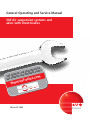
1
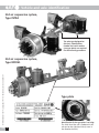
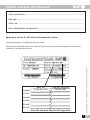
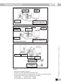
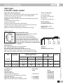
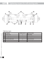
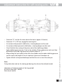
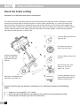
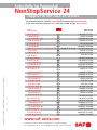
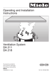
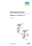
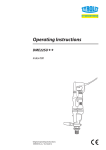
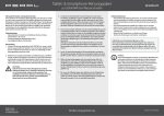
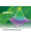
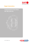
General Operating and Service Manual
SAF Air suspension systems and
axles with drum brakes
ILE
ALTE TS
N
I
G
I
R
R
nd O GINAL PA
u
E
C
I
ERVI
d OR
SAF S RVICE an
om
E
c
.
s
e
l
SAF S
-ax
.saf
w
w
w
Edition 01/2006
Service
Vehicle and axle identification
SAF air suspension system,
Type INTRA
The axle type designation
(Version), identification
number and serial number
(see type plate) are required
for the warranty procedure.
SV11484GB Edition 01/2006 · Last updated 2006-01-13 · Amendments and errors reserved © SAF
SAF air suspension system,
Type MODUL
GB
D 2
Type plate
07
284
05 1 0
Identification if the type plate is missing:
The Serial No. of the axle is embossed in the
axle end on the right-hand side (as seen in
the direction of travel).
Vehicle and axle identification
Trailer manufacturer..................................................................................................................
Body type ..................................................................................................................................
Chassis No. ..............................................................................................................................
Date of delivery/date of registration ........................................................................................
Spare parts service for SAF axles and suspension systems
Exact type designations are required for spare parts orders.
Example
Ident. No.
147 84 60 2 58 0
Prod. No. (Serial No.)
284 05 1 007
1st axle
2nd axle
3rd axle
4th axle
5th axle
Enter the axle data from the SAF type plate
SV11484GB Edition 01/2006 · Last updated 2006-01-13 · Amendments and errors reserved © SAF
Please enter the identification data of the suspension system in the type plate illustrated below so that the correct
information is available when necessary.
3 GB
D
Contents
GB
Page
Identification of SAF axles ........................................................................................................................................2-3
SAF general safety instructions ....................................................................................................................................5
SAF general service instructions ..................................................................................................................................6
Tightening torques........................................................................................................................................................7
Service schedule
S9-4218 / SL9-4218 / Z9-4218 / ZL9-4218 / S9-4220 / SL9-4220 / Z9-4220 / ZL9-4220 / S11-4218 /
SL11-4218 / SZL11-4218 / Z11-4218 / ZL11-4218 / S11-4220 / SL11-4220 / SZL-4220 / Z11-4220 /
ZL11-4220 / ZZLL-4220 ................................................................................................................................................8
SK RS / RZ 9042 / 11242 ..............................................................................................................................................9
Z8-3718 / S9-3718 / SL9-3718 / Z9-3720 / ZL9-3720 / S11-3720 / SL11-3720 / Z11-3720 / ZL11-3720 ....................10
SK RS / RZ 6537 / 9037 / 11037 ................................................................................................................................11
S7-3015 / Z7-3015 / S9-3020 / Z9-3020 / ZL9-3020 / Z11-3020 / ZL11-3020 ............................................................12
SK RS / RZ 6530 / 9030 / 11030 / RZ 12030 ..............................................................................................................13
SK RS / RZ 12242........................................................................................................................................................14
K RS / RZ 14242 / 16242 ............................................................................................................................................15
Tightening torques and adjustment instructions
SV11484GB Edition 01/2006 · Last updated 2006-01-13 · Amendments and errors reserved © SAF
for self-steering axles ............................................................................................................................................16-17
General information
GB 4
Check the brake setting..............................................................................................................................................18
Adjustment of HALDEX automatic slack adjusters ................................................................................................19-20
Adjustment of S-ABA automatic slack adjusters ........................................................................................................21
Tightening instructions for adjustable pivot bolt ........................................................................................................22
Semi-trailer tilt angle..................................................................................................................................................23
Tyre changing on fully loaded trailer with INTRA axle ..............................................................................................24
Adjustment of the air suspension system ride height ................................................................................................25
Axle alignment ..........................................................................................................................................................26
General safety instructions
Please observe the following safety instructions in order to maintain the operational and road safety
of your SAF axles and suspension systems:
1. The wheel contact surfaces between the wheel disc and wheel hub and the wheel nut contact surface at the
wheel disc must not be additionally painted. The contact surfaces must be clean, smooth and free from
grease. Failure to observe this may result in the wheel coming loose. Any additional instructions of the wheel
manufacturer must also be observed.
2. Only the wheel and tyre sizes approved by the trailer builder may be used. The tyres must always have the
specified inflation pressure.
3. The brake systems of the tractor and the trailer/semi-trailer must be synchronised by means of a tractor/trailer
brake synchronisation not later than 5,000 km after the initial start of operation of the trailer/semi-trailer
in order to ensure a safe and uniform braking behaviour and uniform brake pad wear. Tractor/trailer brake
synchronisations should be carried out by appropriately qualified and equipped brake workshops.
The use of an additional braking system, such as a trailer anti-jackknife brake is forbidden by law on vehicles
with type approval after January 1999.
4. Before starting a journey, ensure that the maximum permissible axle load is not exceeded and that the load is
distributed equally and uniformly.
5. On trailers with air suspension, ensure that the air bags are completely filled with air before starting the
journey. Incompletely filled air bags may result in damage to axles, suspension, frame and superstructure and
impair road safety.
6. Ensure that the brakes are not overheated by continuous operation.
With drum brakes, overheating can result in a hazardous deterioration in the braking efficiency.
7. The parking brake must not be immediately applied when the brakes are hot, as the brake discs and brake
drums may be damaged by different stress fields during cooling.
8. Use the supports provided when loading and unloading in order to avoid damage to the axle.
9. Observe the operating recommendation of the trailer builder for off-road operation of the installed axles and
suspension systems.
The SAF definition of OFF-ROAD means driving on non-asphalted / non-concreted routes, such as e.g. gravel
roads, agricultural and forestry tracks, on construction sites and in gravel pits.
Off-road operation of SAF axles and suspension systems not designed for the purpose may result in damage
and hence to an impairment of road safety.
10. SAF axles and suspension systems require continuous care, service and maintenance in order to maintain
operational and road safety and to be able to recognise natural wear and defects in good time.
The daily inspection of the trailer for road safety before starting the journey is one of the driver’s obligations.
SAF recommends that at least the inspections and maintenance operations described on page 6 should be
carried out.
We recommend the use of original SAF spare parts.
A close-knit service network of SAF partner companies is available for the technical support of the SAF axles and
suspension systems and for the supply of original SAF spare parts (see rear cover or on the Internet under
www.saf-axles.com).
Updates will be published as necessary on the Internet under www.saf-axles.com.
SV11484GB Edition 01/2006 · Last updated 2006-01-13 · Amendments and errors reserved © SAF
With disc brakes, overheating can result in damage to surrounding components – in particular the wheel
bearings. This can result in a significant deterioration in road safety, e.g. failure of wheel bearings.
5 GB
SV11484GB Edition 01/2006 · Last updated 2006-01-13 · Amendments and errors reserved © SAF
General service instructions
•
Caution: After every wheel change, always retighten the wheel nuts to the prescribed torque after 50 km and
again after 150 km.
•
Check the brake lining thickness at regular intervals.
•
Carry out general visual inspections of the brakes, tyres and all suspension components at regular intervals and
check for proper attachment, wear, leaks, corrosion and damage.
•
Carry out regular visual inspections of the wheel bearing unit for grease leaks and axial clearance.
Wheel bearing grease change, see pages 9, 11, 13, 14 and 15.
•
Regularly check the camshaft for smooth return and the slack adjuster for proper function.
•
Lubricate the camshaft at regular intervals.
•
Inspect the brake drum for wear* and cracking at every brake lining change.
Minimum wear limits*, see pages 8 to 15.
•
Replace the brake shoe return springs at every brake lining change.
•
Check the air suspension ride height at regular intervals in accordance with the trailer builder's specifications
and adjust as described on page 25.
•
With aluminium and stainless steel hanger brackets, check that the bolts of the spring brackets and shock
absorbers are tightened to the prescribed torques as described on page 7.
•
On all units, check that the bolts of the U-brackets are tightened to the prescribed torques as described on page 7.
•
For steering axles, observe also the points on pages 16 and 17.
•
Carry out a general safety check in accordance with the statutory provisions.
•
We recommend the use of original SAF spare parts.
* We recommend that a general safety check is carried out when the minimum wear limit is reached.
GB 6
Tightening torques
Tightening torques SAF INTRA with steel hanger bracket
M12 (WAF19)
40 Nm
M20x1.5 (WAF30)
600 Nm
M30 (WAF46)
400 Nm + 120º
M16 (WAF24)
180 Nm for steel plunger piston
80 Nm for plastic plunger piston
Tightening torques SAF INTRA with aluminium hanger bracket and
stainless steel hanger bracket
M12 (WAF19)
40 Nm
M20x1.5 (WAF30)
600 Nm
M20x1.5 (WAF30)
400 Nm
M30 (WAF46)
400 Nm + 120º
M16 (WAF24)
180 Nm for steel plunger piston
80 Nm for plastic plunger piston
NOT MAINTENANCE-FREE!
M30 (WAF46) M24x2 (WAF36)
400 Nm
400 Nm + 120º
M22x1.5 (WAF32) M20 (WAF30)
580 Nm
180 Nm
M12 (WAF19) 80 Nm
for steel plunger piston
Cut-screw
K100x40 (WAF10)
20 Nm
for plastic plunger piston
Attention!
• Threads not to be oiled or greased!
• Pivot bolt on steel hanger brackets maintenance-free.
• Service intervals for aluminium hanger brackets and stainless steel hanger brackets:
first check after 500 km, further check after every 6 months
Spring eye bolt:
Inspection torque 1,200 Nm
Shock absorber bolt: Inspection torque 400 Nm
SV11484GB Edition 01/2006 · Last updated 2006-01-13 · Amendments and errors reserved © SAF
Tightening torques SAF MODUL
7 GB
Service schedule
Axle types
S9-4218 / SL9-4218 / Z9-4218 / ZL9-4218 / S9-4220 / SL9-4220 /
Z9-4220 / ZL9-4220 / S11-4218 / SL11-4218 / SZL11-4218 /
Z11-4218 / ZL11-4218 / S11-4220 / SL11-4220 / SZL11-4220 /
Z11-4220 / ZL11-4220 / ZZL11-4220
Wheel bearing play, wheel bearing grease
Adjustment of wheel bearing play not necessary.
Note during brake repairs:
Lubricate the camshafts, rotating the camshaft through 360° several times.
Use a vacuum cleaner to remove brake dust.
Use of a high-pressure cleaner or liquid cleanser is not permitted on the
brake drum and brake hub.
Remove old grease from the stub axle and regrease.
Replace the O-ring.
Replace the brake shoe return springs at every brake pad change.
Grease specifications
For camshaft
SAF Part No. 5 387 0011 05
For axle stub end:
SAF mounting paste
SAF Part No. 5 387 0021 05
For ball in brake carrier:
Copper paste
SAF Part No. 5 387 0014 01
BRAKE SNK 420
Max. admissible brake drum machining diameter:
Max. admissible brake drum wear diameter:
Brake lining qualities recommended and approved by SAF:
Machine new brake linings to diameter + 0.3 mm of the brake drum.
When riveting on, observe the lining form (see instructions in the pack).
Brake
size
SAF Part No.
Brake lining
Brake drum / brake lining
Repair stages in mm
Brake
lining
d0-420.0
d1-422.0
d2-424.0
Rivet
Number per axle
3 057 3960 00
20.6
20.0
21.6
21.0
22.6
22.0
4
4
64
B 8 x 15
x 200
3 057 3966 00
20.6
20.0
21.6
21.0
22.6
22.0
4
4
64
B 8 x 15
SAF Part No.
4 434 3828 00
3 349 1001 00
4 434 3822 00
424.0
d2
2. Rep.-Stufe
2nd
oversize
d1
422.0
Rivet
DIN 7338
x 180
Assembly tools
Axle nut wrench
Brake shoe tensioner
Puller for wheel hub
GB 8
1. oversize
Rep.-Stufe
1st
424.0 mm
425.0 mm
SAF 396, BREMSKERL 6386
Normal dimension 1st repair stage 2nd repair stage
SNK 420
420.0
d0
On left-hand side in direction of travel:
Left-hand thread
On right-hand side in direction of travel:
Right-hand thread
Pretightening: 150 Nm, then turn the hub unit
slowly by 5 revolutions.
Final tightening: Retighten by 1 increment (30º)
Marking of the nuts with left-hand thread:
Milled groove on outside of hexagon.
Max. permissible axial backlash of hub unit:
0 - 0.20 mm
Normalmaß
nominal
size
SV11484GB Edition 01/2006 · Last updated 2006-01-13 · Amendments and errors reserved © SAF
Tighten axle nuts
Service schedule
Axle types
SK RS / RZ 9042 / 11242
Wheel bearing play, wheel bearing grease
Adjustment of wheel bearing play not necessary.
Change the wheel bearing grease after 500,000 km or 50 months.
Inspect taper roller bearing for serviceability at grease changes.
Replace the O-ring and fit the wheel cap.
Note during brake repairs:
Lubricate the camshafts, rotating the camshaft through 360° several times.
Do not dismantle the wheel bearing unit.
Use a vacuum cleaner to remove brake dust.
Use of a high-pressure cleaner or liquid cleanser is not permitted on the
brake drum and brake hub.
Remove old grease from the stub axle and regrease.
Replace the brake shoe return springs at every brake pad change.
Grease specifications
For wheel bearings:
SAF Part No. 5 387 0011 05
For camshaft
SAF Part No. 5 387 0011 05
For axle stub end:
SAF mounting paste
SAF Part No. 5 387 0021 05
For ball in brake carrier:
Copper paste
SAF Part No. 5 387 0014 01
Brake
size
SAF Part No.
Brake lining
Brake drum / brake lining
Repair stages in mm
Brake
lining
Normal dimension 1st repair stage 2nd repair stage
SNK 420
d0-420.0
d1-422.0
d2-424.0
Rivet
Rivet
DIN 7338
Number per axle
x 180
3 057 3960 00
20.6
20.0
21.6
21.0
22.6
22.0
4
4
64
B 8 x 15
x 200
3 057 3966 00
20.6
20.0
21.6
21.0
22.6
22.0
4
4
64
B 8 x 15
Assembly tools
Axle nut wrench
Brake shoe tensioner
Brake drum mounting flanges
Wheel bearing mounting mandrel
Puller for wheel hub
SAF Part No.
1 012 0024 00
3 349 1001 00
3 434 1040 01
3 434 1043 00
4 434 3822 00
424.0
d2
2. Rep.-Stufe
2nd
oversize
422.0
d1
1. oversize
Rep.-Stufe
1st
420.0
424.0 mm
425.0 mm
SAF 396, BREMSKERL 6386
SV11484GB Edition 01/2006 · Last updated 2006-01-13 · Amendments and errors reserved © SAF
BRAKE SNK 420
Max. admissible brake drum machining diameter:
Max. admissible brake drum wear diameter:
Brake lining qualities recommended and approved by SAF:
Machine new brake linings to diameter + 0.3 mm of the brake drum.
When riveting on, observe the lining form (see instructions in the pack).
d0
On left-hand side in direction of travel:
Left-hand thread
On right-hand side in direction of travel:
Right-hand thread
Tightening torque 900 Nm. Each hub unit must be
rotated smoothly at least twice while tightening
the bolts.
Marking of the nuts with left-hand thread:
Milled groove on outside of hexagon.
Max. permissible axial backlash of hub unit:
0 - 0.20 mm
Normalmaß
nominal
size
Tighten axle nuts
9 GB
Service schedule
Axle types
Z8-3718 / S9-3718 / SL9-3718 / Z9-3720 / ZL9-3720 / S11-3720 /
SL11-3720 / Z11-3720 / ZL11-3720
Wheel bearing play, wheel bearing grease
Adjustment of wheel bearing play not necessary.
Note during brake repairs:
Lubricate the camshafts, rotating the camshaft through 360° several
times.
Use a vacuum cleaner to remove brake dust.
Use of a high-pressure cleaner or liquid cleanser is not permitted on
the brake drum and brake hub.
Remove old grease from the stub axle and regrease.
Replace the O-ring.
Replace the brake shoe return springs at every brake pad change.
Grease specifications
For camshaft
SAF Part No. 5 387 0011 05
For axle stub end:
SAF mounting paste
SAF Part No. 5 387 0021 05
For ball in brake carrier:
Copper paste
SAF Part No. 5 387 0014 01
SV11484GB Edition 01/2006 · Last updated 2006-01-13 · Amendments and errors reserved © SAF
BRAKE SNK 367
Max. admissible brake drum machining diameter:
Max. admissible brake drum wear diameter:
Brake lining qualities recommended and approved by SAF:
Machine new brake linings to diameter + 0.3 mm of the brake drum.
When riveting on, observe the lining form (see instructions in the pack).
Brake
size
SAF Part No.
Brake lining
Brake drum / brake lining
Repair stages in mm
Brake
lining
d0-367.0
d1-369.0
d2-371.0
Rivet
Number per axle
3 057 3168 00
21.1
20.5
22.1
21.5
23.1
22.5
4
4
64
B 8 x 15
x 200
3 057 3170 00
21.1
20.5
22.1
21.5
23.1
22.5
4
4
64
B 8 x 15
SAF Part No.
4 434 3828 00
3 349 1001 00
3 434 1040 01
4 434 3822 00
371.0
d2
2. Rep.-Stufe
2nd
oversize
d1
369.0
Rivet
DIN 7338
x 180
Assembly tools
Axle nut wrench
Brake shoe tensioner
Brake drum mounting flanges
Puller for wheel hub
GB 10
1. oversize
Rep.-Stufe
1st
371.0 mm
372.0 mm
SAF 396, BREMSKERL 6386
Normal dimension 1st repair stage 2nd repair stage
SNK 367
367.0
d0
On left-hand side in direction of travel:
Left-hand thread
On right-hand side in direction of travel:
Right-hand thread
Pretightening: 150 Nm, then turn the hub unit
slowly by 5 revolutions.
Final tightening: Retighten by 1 increment (30º)
Marking of the nuts with left-hand thread:
Milled groove on outside of hexagon.
Max. permissible axial backlash of hub unit:
0 - 0.20 mm
Normalmaß
nominal
size
Tighten axle nuts
Service schedule
Axle types
SK RS / RZ 6537 / 9037 / 11037
Wheel bearing play, wheel bearing grease
Adjustment of wheel bearing play not necessary.
Change the wheel bearing grease after 500,000 km or 50 months.
Inspect taper roller bearing for serviceability at grease changes.
Replace the O-ring and fit the wheel cap.
Note during brake repairs:
Lubricate the camshafts, rotating the camshaft through 360° several times.
Do not dismantle the wheel bearing unit.
Use a vacuum cleaner to remove brake dust.
Use of a high-pressure cleaner or liquid cleanser is not permitted on the
brake drum and brake hub.
Remove old grease from the stub axle and regrease.
Replace the brake shoe return springs at every brake pad change.
Grease specifications
For wheel bearings:
SAF Part No. 5 387 0011 05
For camshaft
SAF Part No. 5 387 0011 05
For axle stub end:
SAF mounting paste
SAF Part No. 5 387 0021 01
For ball in brake carrier:
Copper paste
SAF Part No. 5 387 0014 01
Brake
size
SAF Part No.
Brake lining
371.0
d2
2. Rep.-Stufe
2nd
oversize
369.0
d1
1. oversize
Rep.-Stufe
1st
367.0
371.0 mm
372.0 mm
SAF 396, BREMSKERL 6386
Brake drum / brake lining
Repair stages in mm
Brake
lining
Normal dimension 1st repair stage 2nd repair stage
Rivet
Rivet
DIN 7338
Number per axle
SNK 367
d0-367.0
d1-369.0
d2-371.0
x 150
3 057 3174 00
21.1
20.5
22.1
21.5
23.1
22.5
4
4
64
B 8 x 15
x 180
3 057 3168 00
21.1
20.5
22.1
21.5
23.1
22.5
4
4
64
B 8 x 15
x 200
3 057 3170 00
21.1
20.5
22.1
21.5
23.1
22.5
4
4
64
B 8 x 15
Assembly tools
Axle nut wrench
Brake shoe tensioner
Brake drum mounting flanges
Wheel bearing mounting mandrel
Brass bush mounting device
Brass bush mounting mandrel
Puller for wheel hub
SAF Part No.
1 012 0024 00
3 349 1001 00
3 434 1040 01
3 434 1058 00
1 434 1056 00
1 434 1055 00
4 434 3822 00
SV11484GB Edition 01/2006 · Last updated 2006-01-13 · Amendments and errors reserved © SAF
BRAKE SNK 367
Max. admissible brake drum machining diameter:
Max. admissible brake drum wear diameter:
Brake lining qualities recommended and approved by SAF:
Machine new brake linings to diameter + 0.3 mm of the brake drum.
When riveting on, observe the lining form (see instructions in the pack).
d0
On left-hand side in direction of travel:
Left-hand thread
On right-hand side in direction of travel:
Right-hand thread
Tightening torque 900 Nm. Each hub unit must
be rotated smoothly at least twice while
tightening the bolts.
Marking of the nuts with left-hand thread:
Milled groove on outside of hexagon.
Max. permissible axial backlash of hub unit:
0 - 0.20 mm
Normalmaß
nominal
size
Tighten axle nuts
11 GB
Service schedule
Axle types
S7-3015 / Z7-3015 / S9-3020 / SL9-3020 / Z9-3020 / ZL9-3020 /
Z11-3020 / ZL11-3020
Wheel bearing play, wheel bearing grease
Adjustment of wheel bearing play not necessary.
Note during brake repairs:
Lubricate the camshafts, rotating the camshaft through 360° several
times.
Use a vacuum cleaner to remove brake dust.
Use of a high-pressure cleaner or liquid cleanser is not permitted on
the brake drum and brake hub.
Remove old grease from the stub axle and regrease.
Replace the O-ring.
Replace the brake shoe return springs at every brake pad change.
Grease specifications
For camshaft
SAF Part No. 5 387 0011 05
For axle stub end:
SAF mounting paste
SAF Part No. 5 387 0021 05
For ball in brake carrier:
Copper paste
SAF Part No. 5 387 0014 01
SV11484GB Edition 01/2006 · Last updated 2006-01-13 · Amendments and errors reserved © SAF
BRAKE SNK 300
Max. admissible brake drum machining diameter:
Max. admissible brake drum wear diameter:
Brake lining qualities recommended and approved by SAF:
Machine new brake linings to diameter + 0.3 mm of the brake drum.
When riveting on, observe the lining form (see instructions in the pack).
Brake
size
SAF Part No.
Brake lining
Brake drum / brake lining
Repair stages in mm
Brake
lining
d0-300.0
d1-302.0
d2-303.0
Rivet
Number per axle
3 057 3133 00
15.5
16.5
16.7
17.7
17.1
18.1
4
4
64
B 8 x 15
x 200
3 057 3124 00
15.5
16.5
16.7
17.7
17.1
18.1
4
4
64
B 8 x 15
SAF Part No.
4 434 3828 00
3 301 0010 00
4 434 3822 00
303.0
d2
2. Rep.-Stufe
2nd
oversize
d1
302.0
Rivet
DIN 7338
x 150
Assembly tools
Axle nut wrench
Puller for wheel hub
Puller for wheel hub
GB 12
1. oversize
Rep.-Stufe
1st
303.0 mm
304.0 mm
SAF 396, BREMSKERL 6386
Normal dimension 1st repair stage 2nd repair stage
SNK 300
300.0
d0
On left-hand side in direction of travel:
Left-hand thread
On right-hand side in direction of travel: Righthand thread
Pretightening: 150 Nm, then turn the hub unit
slowly by 5 revolutions.
Final tightening: Retighten by 1 increment (30º)
Marking of the nuts with left-hand thread:
Milled groove on outside of hexagon.
Max. permissible axial backlash of hub unit:
0 - 0.20 mm
Normalmaß
nominal
size
Tighten axle nuts
Service schedule
Axle types
SK RS / RZ 6530 / 9030 / 11030 / RZ 12030
Adjust wheel bearing clearance:
Tighten the WAF 85 axle nut to 150 Nm, turning the wheel hub
at the same time.
Turn back the axle nut by 2 1/2 holes of the lock washer.
Push on the lock washer and secure the axle nut with the
locking pin.
Tighten the lock nut to 400 Nm.
Check the running and rock of the wheel bearing.
The wheel must turn without resistance and no rock may be felt
at the wheel rim. Correct the adjustment, if necessary.
Replace the O-ring and fit the wheel cap.
Replace the brake shoe return springs at every brake pad change.
Grease specifications
For wheel bearings:
SAF Part No. 5 387 0011 05
For camshaft:
SAF Part No. 5 387 0011 05
For axle stub end:
SAF mounting paste
SAF Part No. 5 387 0021 01
For ball in brake carrier:
Copper paste
SAF Part No. 5 387 0014 01
Brake
size
SAF Part No.
Brake lining
Brake drum / brake lining
Repair stages in mm
Brake
lining
Normal dimension 1st repair stage 2nd repair stage
SNK 300
d0-300.0
d1-302.0
d2-303.0
Rivet
Rivet
DIN 7338
Number per axle
x 150
3 057 3133 00
15.5
16.5
16.7
17.7
17.1
18.1
4
4
64
B 8 x 15
x 200
3 057 3124 00
15.5
16.5
16.7
17.7
17.1
18.1
4
4
64
B 8 x 15
Assembly tools
Axle nut wrench
Puller for wheel hub
Fitting mandrel for wheel bearing and seal ring
Fitting mandrel for wheel bearing
Brass bush mounting mandrel
Brass bush mounting device
SAF Part No.
4 434 3828 00
3 301 0010 00
3 434 1014 00
3 434 3308 00
1 434 1055 00
1 434 1056 00
303.0
d2
2. Rep.-Stufe
2nd
oversize
302.0
d1
1. oversize
Rep.-Stufe
1st
300.0
303.0 mm
304.0 mm
SAF 396, BREMSKERL 6386
SV11484GB Edition 01/2006 · Last updated 2006-01-13 · Amendments and errors reserved © SAF
BRAKE SNK 300
Max. admissible brake drum machining diameter:
Max. admissible brake drum wear diameter:
Brake lining qualities recommended and approved by SAF:
Machine new brake linings to diameter + 0.3 mm of the brake drum.
When riveting on, observe the lining form (see instructions in the pack).
d0
Note during brake repairs:
Lubricate the camshafts, rotating the camshaft
through 360° several times.
Use a vacuum cleaner to remove brake dust.
Use of a high-pressure cleaner or liquid cleanser is
not permitted on the brake drum and brake hub.
Remove old grease from the stub axle and regrease.
Max. permissible axial backlash of hub unit:
0 - 0.20 mm
Normalmaß
nominal
size
Tighten axle nuts
13 GB
Service schedule
Axle types
SK RS / RZ 12242
Grease specifications
Adjust wheel bearing clearance:
Tighten the WAF 85 axle nut to 150 Nm, turning the wheel hub at
the same time.
Turn back the axle nut by 2 1/2 holes of the lock washer.
Push on the lock washer and secure the axle nut with the locking pin.
Tighten the lock nut to 400 Nm.
Check the running and rock of the wheel bearing.
The wheel must turn without resistance and no rock may be felt at
the wheel rim. Correct the adjustment, if necessary.
Replace the O-ring and fit the wheel cap.
Replace the brake shoe return springs at every brake pad change.
For wheel bearings:
SAF Part No. 5 387 0011 05
For camshaft
SAF Part No. 5 387 0011 05
For axle stub end:
SAF mounting paste
SAF Part No. 5 387 0021 01
For ball in brake carrier:
Copper paste
SAF Part No. 5 387 0014 01
SV11484GB Edition 01/2006 · Last updated 2006-01-13 · Amendments and errors reserved © SAF
Brake
size
SAF Part No.
Brake lining
Brake drum / brake lining
Repair stages in mm
Brake
lining
d0-420.0
d1-422.0
d2-424.0
Rivet
Number per axle
3 057 3960 00
20.6
20.0
21.6
21.0
22.6
22.0
4
4
64
B 8 x 15
x 200
3 057 3966 00
20.6
20.0
21.6
21.0
22.6
22.0
4
4
64
B 8 x 15
SAF Part No.
4 434 3828 00
3 301 0010 00
4 434 3822 00
3 434 3320 00
3 434 1036 00
3 349 1001 00
424.0
d2
2. Rep.-Stufe
2nd
oversize
d1
422.0
Rivet
DIN 7338
x 180
Assembly tools
Axle types 12242
Axle nut wrench
Puller for wheel hub
Universal puller for wheel hub
Fitting mandrel for wheel bearing and seal ring
Fitting mandrel for cassette seal ring
Brake shoe tensioner
GB 14
420.0
424.0 mm
425.0 mm
SAF 396, BREMSKERL 6386
Normal dimension 1st repair stage 2nd repair stage
SNK 420
1. oversize
Rep.-Stufe
1st
BRAKE SNK 420
Max. admissible brake drum machining diameter:
Max. admissible brake drum wear diameter:
Brake lining qualities recommended and approved by SAF:
Machine new brake linings to diameter + 0.3 mm of the brake drum.
When riveting on, observe the lining form (see instructions in the pack).
d0
Note during brake repairs:
Lubricate the camshafts, rotating the camshaft
through 360° several times.
Do not dismantle the wheel bearing unit.
Use a vacuum cleaner to remove brake dust.
Use of a high-pressure cleaner or liquid cleanser is
not permitted on the brake drum and brake hub.
Remove old grease from the stub axle and regrease.
Max. permissible axial backlash of hub unit:
0 - 0.20 mm
Normalmaß
nominal
size
Tighten axle nuts
Service schedule
Axle types
K RS / RZ 14242 / 16242
Adjust wheel bearing clearance:
Tighten the axle nut, turning the wheel hub until a slight resistance is felt.
Turn back the axle nut by 1/12 turn to the next locking possibility.
Lock the axle nut with the cotter pin.
Turn back the wheel hub slightly against the front bearing with the wheel
hub puller.
Seal the thread of the wheel cap.
Screw on the wheel cap.
Check the running and rock of the wheel bearing.
The wheel must turn without resistance and no rock may be felt at the
wheel rim. Correct the adjustment, if necessary.
Replace the brake shoe return springs at every brake pad change.
Grease specifications
For wheel bearings:
SAF Part No. 5 387 0011 05
For camshaft
SAF Part No. 5 387 0011 05
For axle stub end:
SAF mounting paste
SAF Part No. 5 387 0021 01
For ball in brake carrier:
Copper paste
SAF Part No. 5 387 0014 01
Brake
size
SAF Part No.
Brake lining
424.0
d2
2. Rep.-Stufe
2nd
oversize
422.0
d1
1. Rep.-Stufe
1st
oversize
420.0
424.0 mm
425.0 mm
SAF 396, BREMSKERL 6386
Brake drum / brake lining
Repair stages in mm
Brake
lining
Normal dimension 1st repair stage 2nd repair stage
Rivet
Rivet
DIN 7338
Number per axle
SNK 420
d0-420.0
d1-422.0
d2-424.0
x 180
3 057 3960 00
20.6
20.0
21.6
21.0
22.6
22.0
4
4
64
B 8 x 15
x 200
3 057 3966 00
20.6
20.0
21.6
21.0
22.6
22.0
4
4
64
B 8 x 15
Assembly tools
Axle types
Axle nut wrench
Puller for wheel hub
Universal puller for wheel hub
Fitting mandrel for wheel bearing and seal ring
Brake shoe tensioner
46 mm dia. brass bush driver mandrel
50/46 mm and 42/38 mm dia. mounting mandrel
SAF Part No.
14242
4 434 3822 00
3 349 1001 00
1 434 1056 00
1 434 1055 00
16242
1 012 0013 00
3 301 0007 01
4 434 3822 00
3 434 3301 00
3 349 1001 00
1 434 1056 00
1 434 1055 00
SV11484GB Edition 01/2006 · Last updated 2006-01-13 · Amendments and errors reserved © SAF
BRAKE SNK 420
Max. admissible brake drum machining diameter:
Max. admissible brake drum wear diameter:
Brake lining qualities recommended and approved by SAF:
Machine new brake linings to diameter + 0.3 mm of the brake drum.
When riveting on, observe the lining form (see instructions in the pack).
d0
Note during brake repairs:
Lubricate the camshafts, rotating the camshaft
through 360° several times.
Do not dismantle the wheel bearing unit.
Use a vacuum cleaner to remove brake dust.
Use of a high-pressure cleaner or liquid cleanser is
not permitted on the brake drum and brake hub.
Remove old grease from the stub axle and regrease.
Max. permissible axial backlash of wheel bearing:
0 - 0.20 mm
Normalmaß
nominal
size
Tighten axle nuts
15 GB
Tightening torques for self-steering axles
5
6
7
6
7
2
1
3
4
3
2
1
SV11484GB Edition 01/2006 · Last updated 2006-01-13 · Amendments and errors reserved © SAF
Tightening torques
No.
Designation
1
2
3
4
5
6
7
Ball joint screw
Reatining clamp screw
Steering damper screw
Lock cylinder screw
Stabilising cylinder screw
Lock nut
Cover plate screw
GB 16
Number per axle
2
10
2
4
4
2
6
Tightening torque
M30 (340 Nm)
M12 (80 - 90 Nm)
M24 (600 - 660 Nm)
M6 (8 - 10 Nm)
M16 (180 ± 30 Nm)
M20 (is locked against the thrust rod)
M8 (25 - 30 Nm)
–
–
–
–
–
Dimension “A” must be the same; observe the toe-in (approx. 4.0 mm/m)
Dimension “B” is 537 mm; engage the reversing lock
On versions with pneumatic stabilisation, a steering damper must be used.
On versions without pneumatic stabilisation, a steering damper must be used.
Check: Backlash-free seating of the piston rods of the stabilising cylinders.
Apply stabilising pressure (min. 2 bar) to the cylinders. Piston and pressure rods must then
be backlash-free (under slight pressure); otherwise adjust at “C”.
– When setting the track width on the trailer, the cylinders must be under stabilising pressure
and the correct ride height of the air suspension system must have been set.
– Tighten all bolts to the prescribed torque and lock the nuts or insert the cotter pin.
Note:
During lubrication work on the steering pin bearing, the axle must be relieved (raised).
Lubrication at the bearing points of the king pin bolt
for the first time after 1 month,
then every 6 months
SV11484GB Edition 01/2006 · Last updated 2006-01-13 · Amendments and errors reserved © SAF
Adjustment instruction for self-steering axles
17 GB
General information
Check the brake setting
Adjustment of S-cam brakes with manual slack adjusters
The natural wear of the brake drum and brake lining necessitate frequent adjustment of the wheel brakes in order to
maintain the maximum stroke of the brake cylinders. In order to achieve good braking, it is essential to minimise the
clearance between the brake drum and brake lining. In order to check the clearance, the service brake is applied with
full pressure and the stroke of the brake cylinder checked. If the stroke at the yoke end is more than 2/3 of the maximum
cylinder stroke, the brake must be urgently adjusted. If the brakes are correctly adjusted, it should not be possible to
move the piston rod more than 15 mm by hand.
Turn the adjusting screw to the
right until the
SV11484GB Edition 01/2006 · Last updated 2006-01-13 · Amendments and errors reserved © SAF
brake shoes are firmly up
against the brake drum.
No clearance between
piston and diaphragm
permitted in the rest
position.
Turn the adjusting screw to the
left until
the free travel of the slack
adjuster (at 127 mm) is
approx. 10 - 15 mm.
Adjustment is performed at the
adjustment screw (WAF 19)
It must be possible to turn the
wheel freely without braking
(without scraping noises).
Special instructions apply for automatic slack adjusters (see adjustment procedure on the following
pages).
A = Angle must not exceed 90° at 1/2 stroke.
B = No contact permissible between slack adjuster and axle beam during emergency braking.
L = Observe piston rod length as per the SAF specifications.
GB 18
General information
HALDEX automatic slack adjuster
Note when changing over from mechanical slack adjuster to automatic slack adjuster:
In order to avoid damage to the wheel brake, install only the automatic slack adjuster with the prescribed adjustment
gate and corresponding mounting point strap approved by SAF for the respective axle type.
Changes to the effective brake lever lengths are not admissible.
The field installation of automatic slack adjusters does not require type approval so that no inspection by the technical
inspection authorities (TÜV) is necessary.
SV11484GB Edition 01/2006 · Last updated 2006-01-13 · Amendments and errors reserved © SAF
Technical information on SAF spare part numbers and correspondence of slack
adjusters and axle types can be obtained from the SAF service partners.
19 GB
Adjustment, HALDEX
Adjustment of HALDEX automatic slack adjusters
L
10
7
1
2
4
3
• Grease cotter pin (8) and secure.
• Hook in return spring (10).
SV11484GB Edition 01/2006 · Last updated 2006-01-13 · Amendments and errors reserved © SAF
• Turn the control arm in the direction of the arrow
(working direction of the slack adjuster) into its end
position without using force
11
• Cams and brake shoes are in the zero position.
• In this end position of control arm (2), tighten mounting
bolts (4).
• With the fixed mounting point (11), ensure that the
2 U-profiles engage correctly in one another.
NOTE FOR SELF-STEERING AXLES:
• Observe the correct piston rod length “L” as given in the
•
Weld on mounting point strap (3) in this position.
SAF specifications.
•
Fix the slack adjuster on the camshaft.
• Brake chambers
Before installation, ensure that the brake chamber is in
its starting position.
• Spring brake chambers, on the other hand, must be
under full working pressure (min. 6 bar).
IMPORTANT: If this is not observed, the basic setting will be wrong!
• Grease the camshaft.
• Install mounting point strap (3); be sure to use two
mounting bolts (4).
• Axial clearance: Adjust the nominal value of 0.5 - 2 mm
using shims.
• Adjust the clearance of the brake lining by turning
adjusting screw (1) in clock-wise direction until the brake
lining is in contact with the brake drum. Then back off
adjusting screw (1) by 3/4 turn.
Do not use an impact wrench!
FUNCTION CHECK
• The arrow mark (7) points in the braking direction.
• If the adjustment coupling is functioning correctly, a
torque of at least 18 Nm must be felt when backing off
adjusting screw (1); a ratchet noise should also be clearly
audible.
• Turn adjusting screw (1) until the bore in the slack
adjuster (8.1) is aligned with the bore in the yoke end
(9) (see figure).
• Actuate the service brake several times, check the free
running of the brake drum, check the clearance.
If necessary, repeat the adjustment of the slack adjuster.
• Install the slack adjuster on the camshaft.
GB 20
Adjustment, S-ABA
Adjustment of S-ABA automatic slack adjusters
L
10
7
1
2
4
3
• Axial clearance: Adjust the nominal value of 0.5 - 2 mm
using shims.
• Adjust the control arm.
• Observe the correct piston rod length “L” as given in the
SAF specifications.
• Observe the possible setting range for the control lever
position.
• Brake chambers
Before installation, ensure that the brake chamber is in
its starting position.
• Spring brake chambers, on the other hand, must be
under full working pressure (min. 6 bar).
IMPORTANT: If this is not observed, the basic
setting will be wrong!
• Grease the camshaft.
• Install mounting point strap (3); be sure to use two
mounting bolts (4).
• Install the slack adjuster on the camshaft.
• The arrow mark (7) points in the braking direction.
• Turn adjusting screw (1) until the bore in the slack
adjuster (8.1) is aligned with the bore in the yoke end
(9) (see figure).
• With the fixed mounting point, ensure that the 2
U-profiles engage correctly in one another.
• Grease cotter pin (8) and secure.
• Hook in return spring (10).
• Fix the slack adjuster on the camshaft.
• Adjust the clearance of the brake lining by turning
adjusting screw (1) in clock-wise direction until the brake
lining is in contact with the brake drum. Then back off
adjusting screw (1) by 3/4 turn.
Do not use an impact wrench!
FUNCTION CHECK
• If the adjustment coupling is functioning correctly, a
torque of at least 18 Nm must be felt when backing off
adjusting screw (1); a ratchet noise should also be clearly
audible.
• Actuate the service brake several times, check the free
running of the brake drum, check the clearance.
If necessary, repeat the adjustment of the slack adjuster.
SV11484GB Edition 01/2006 · Last updated 2006-01-13 · Amendments and errors reserved © SAF
• Cams and brake shoes are in the zero position.
21 GB
General information
Tightening instructions for adjustable pivot bolt
Attention:
Tightening always within the
specified ride height range!
No paint residues between
eccentric/thrust washer and hanger!
SV11484GB Edition 01/2006 · Last updated 2006-01-13 · Amendments and errors reserved © SAF
Pretightening 400 Nm
Use Torque wrench
GB 22
Angle tightening 120°
Use impact wrench or extend
lever to 2.5 m
Bolt head always on the eccentric
washer side.
Marking for angle tightening
Visual inspection
General information
Semi-trailer tilt angle
Ride heights
Adjust the ride height of the air suspension axles to the permissible range indicated in the corresponding SAF
documents.
With single axles, allow for a minimum suspension travel of 60 mm.
For trailers with multiple axles, allow for a minimum suspension travel of 70 mm.
SV11484GB Edition 01/2006 · Last updated 2006-01-13 · Amendments and errors reserved © SAF
Exception:
For multi-axle trailers with lift axles, the minimum suspension travel at the lift axle should not be less than 100 mm
in order to ensure an adequate ground clearance.
23 GB
General information
Tyre changing on fully loaded trailer with INTRA axle
Jack positioning points:
SV11484GB Edition 01/2006 · Last updated 2006-01-13 · Amendments and errors reserved © SAF
o.k.
GB 24
o.k.
not o.k.
not o.k.
General information
Adjustment of the air suspension system ride height
Air suspension valve
As standard, SAF air suspension axles and system require only one air suspension valve.
The air suspension valve controls the air bag pressure in relation to the trailer load in order to maintain a constant
ride height in every load condition.
The air suspension valve is fastened to the trailer frame with screws and connected to the axle via the pivot joint
(valve lever and adjustment pipe). On triple-axle trailers, the system is generally connected to the middle axle (normally
in the middle of the axle), and on twin-axle trailers to the rear axle. In special cases (e.g. large trailer tilt angle), the air
suspension valve can be installed in the rear axle.
Installation
The valve lever should be at least 200 mm long and is horizontal when the trailer is in the driving position.
As a function check, move the lever down slightly. Air must now escape via the venting cap into the atmosphere. If air
flows into the air bags when the lever is pushed down, the valve lever has to be turned through 180°. For this the valve
lever has to be disconnected. The ride height is set by adjusting the adjustment pipe in the fulcrums and by turning the
lock nuts.
The adjustment must be carried out with the trailer standing on level ground. It can be carried out with the trailer either
empty or loaded.
Note
For a final check, the air suspension system should be lowered to the suspension stop or raised to the limit (shock
absorbers, stop ropes, air bag length). During this process, the specified angle between valve lever and adjustment pipe
must not be exceeded in order that the valve lever does not move in the wrong direction.
SV11484GB Edition 01/2006 · Last updated 2006-01-13 · Amendments and errors reserved © SAF
For trailers with axle lifting system, the axle to which the system is connected depends on the axle to be lifted.
25 GB
Axle alignment
In order to compensate for production tolerances, an axle alignment and, if necessary, a correction should be carried out.
The maximum permissible deviations (tolerances) of the alignment values are specified by the tyre manufacturer.
The maximum possible wheelbase correction per axle is ± 6 mm.
Conventional adjustment
Determine the lengths of the diagonals A - C and A - F for the middle axle (reference axle) by comparison measurements,
observing the tolerances.
Check the wheelbases B - C and E - F for the front axle and C - D and F - G for the rear axle and correct, if necessary,
observing the tolerances.
Optical adjustment
SV11484GB Edition 01/2006 · Last updated 2006-01-13 · Amendments and errors reserved © SAF
Observe the operating and setting instructions of the measuring system manufacturer.
Measured value A1
Measured value B1
Calculation of the toe-in and
toe-out values:
A1 - B1 (mm)
Measure line
=S
A (m)
S = positive value = Toe-in
S = negative value = Toe-out
Notes
Laser with bracket
1. In order to avoid tyre wear, we recommend that an axle alignment is performed at regular intervals.
2. We recommend the use of an optical measuring system for carrying out the axle alignment.
3. For alignment, only the centres of the middle of the wheel cap or the middle of the axle stub end are of interest
as reference points.
4. Possible causes of deviations in the axle alignment are:
• Loose U-bolts
• Wear of the spring guide bearing
• Deformation of the axle assembly components due to improper use
GB 26
SV11484GB Edition 01/2006 · Last updated 2006-01-13 · Amendments and errors reserved © SAF
NOTIZEN/NOTES/NOTE
27 GB
Soforthilfe im Pannenfall
NonStopService 24
Support in the case of service
Servicefall wählen Sie bitte immer die Rufnummer Ihres Heimatlandes.
· Im
· In the case of service please always dial the number of your own country.
SV11484GB Edition 01/2006 · Last updated 2006-01-13 · Amendments and errors reserved © SAF
Vom Ausland
from abroad
Inland
home country
03 62 27 23 21
0 59 33 07 07
+30 21 09 40 19 80
+386 26 16 58 35
0 19 08 64 90
2 61 10 45 06
0800 72 37 37 84 / 0 73 33 80 81 58
75 72 74 74
9 02 18 19 92
697 91 96
03 88 72 06 43
0 93 51 31 33
+41 19 08 64 90
0 87 02 42 02 37
21 09 40 19 80
06 13 45 17 27
+386 26 16 58 35
02 66 16 55 74
+44 87 02 42 02 37
+32 59 33 07 07
+372 697 91 96
+372 697 91 96
+33 3 88 72 06 43
+386 26 16 58 35
+45 75 72 74 74
+32 59 33 07 07
+34 9 13 82 68 41
06 18 31 98 70
02 12 50 02 60
+39 02 66 16 55 74
+45 75 72 74 74
+42 02 61 10 45 06
0 26 16 58 35
0 21 22 75 13 21
+386 26 16 58 35
A
B
BG
BIH
CH
CZ
D
DK
E
EST
F
FIN
FL
GB
GR
H
HR
I
IRL
L
LT
LV
MC
MK
N
NL
P
PL
RO
RSM
S
SK
SLO
TR
YU
+43 3 62 27 23 21
+32 59 33 07 07
+30 21 09 40 19 80
+386 26 16 58 35
+41 19 08 64 90
+42 02 61 10 45 06
00800 72 37 37 84 / +49 73 33 80 81 58
+45 75 72 74 74
+34 9 13 82 68 41
+372 697 91 96
+33 3 88 72 06 43
+35 8 93 51 31 33
+41 19 08 64 90
+44 87 02 42 02 37
+30 21 09 40 19 80
+36 13 45 17 27
+386 26 16 58 35
+39 02 66 16 55 74
+44 87 02 42 02 37
+32 59 33 07 07
+372 697 91 96
+372 697 91 96
+33 3 88 72 06 43
+386 26 16 58 35
+45 75 72 74 74
+32 59 33 07 07
+34 9 13 82 68 41
+48 6 18 31 98 70
+40 2 12 50 02 60
+39 02 66 16 55 74
+45 75 72 74 74
+42 02 61 10 45 06
+386 26 16 58 35
+90 21 22 75 13 21
+386 26 16 58 35
www.saf-axles.com
Otto Sauer Achsenfabrik GmbH · Hauptstraße 26 · D-63856 Bessenbach
Tel +49 (0) 60 95 / 301-0 · Fax +49 (0) 60 95 / 301-259 · www.saf-axles.com