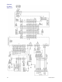
1
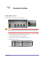
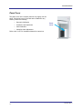
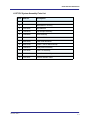
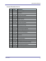
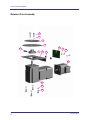
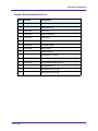
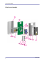
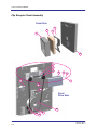
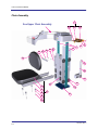
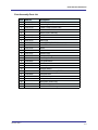
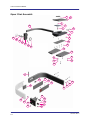
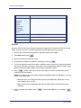
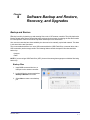
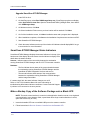
i-CAT FLX Service Manual
IMPORTANT! . . . X-RAY PROTECTION
X-ray equipment may cause injury if used improperly. The instructions contained in this
manual must be read and followed when installing this scanner. The scanner provides a
high degree of protection from unnecessary X-radiation. However, no practical design can
provide complete protection, nor prevent operators from exposing themselves or others to
unnecessary radiation. It is important that you become fully acquainted with applicable
government radiation protection regulations. Many provisions of these regulations are
based on the recommendations of the National Council on Radiation Protection and
Measurements. Recommendations for dental X-ray protection are published in NCRP
Report Number 35 available from NCRP Publications, 7910 Woodmont Ave., Suite 800,
Bethesda, MD 20814, or at www.ncrp.com. Personal radiation monitoring and protective
devices are available. You are urged to use them to protect against unnecessary Xradiation exposure.
032-0332 Rev C
TABLE OF CONTENTS
Chapter 1 - Corrective Action
Replace External Fuses .....................................................................1-1
Panel Cover .........................................................................................1-2
Chapter 2 - Illustrated Parts Breakdown
i-CAT FLX System Assemblies ..........................................................2-2
i-CAT FLX System Assembly Parts List ................................................................ 2-3
Overhead Assembly ...........................................................................2-4
Overhead Assembly Parts List .............................................................................. 2-5
Rotation Drive Assembly ...................................................................2-6
Rotation Drive Assembly Parts List ....................................................................... 2-7
X-Ray Source Assembly ....................................................................2-8
X-Ray Source Assembly Parts List ........................................................................ 2-9
Flip Receptor Panel Assembly ........................................................2-10
Flip Receptor Panel Assembly Parts List ............................................................ 2-11
Chair Assembly .................................................................................2-12
Chair Assembly Parts List .................................................................................... 2-13
Upper Chair Assembly .....................................................................2-14
Upper Chair Assembly Parts List ......................................................................... 2-15
Chapter 3 - Service Account Menu
Log In ...................................................................................................3-1
Run Utilities .........................................................................................3-1
Roll-Off ..................................................................................................................... 3-2
Chapter 4 - Software Backup and Restore, Recovery, and Upgrades
Backup and Restore ...........................................................................4-1
Backup Files ............................................................................................................ 4-1
Restore Files ............................................................................................................ 4-4
Backup and Restore User Account Data ............................................................... 4-4
Restore Operating Environment .......................................................4-5
Boot the Scanner Controller from the Bootable UFD .......................................... 4-5
Install the Operating System Image ....................................................................... 4-5
032-0332 Rev C
-iii
i-CAT FLX Service Manual
Software Upgrades .............................................................................4-6
Manually Copy Site-Customized Data ................................................................... 4-7
Repartition and Upgrade Scanner Controller Software for Systems
with a Single Disk Partition to Version 2.1.0 ......................................................... 4-7
Upgrade Scanner Controller Software from 2.0.1 to 2.1.0 ................................... 4-9
Upgrade Clinical Software .................................................................................... 4-10
SmartScan STUDIO Manager Status Indicators ............................4-12
Make a Backup Copy of the Software Package
onto a Blank UFD ..............................................................................4-12
SmartScan STUDIO Manager Settings Window .............................4-13
Product Version ..................................................................................................... 4-13
Rescan .................................................................................................................... 4-13
Chapter 5 - IEC Command Codes
Home Commands ...............................................................................5-1
Movement Commands .......................................................................5-1
Read Commands ................................................................................5-2
Set Commands ....................................................................................5-4
X-Ray Commands ...............................................................................5-5
Miscellaneous Commands .................................................................5-5
Chapter 6 - System Schematics
-iv
032-0332 Rev C
Chapter
Corrective Action
1
Replace External Fuses
Four external fuses are located on the back of the overhead.
WARNING
To avoid electrical shock, remove power from the system before removing fuses. Do not touch the
metal parts of the fuse holder until fully removed from the system. Touch the plastic cap only.
1. Press the OFF button on the operator control box. The scanner shuts down and the POWER
indicators on the operator control box and scanner go OFF.
2. At rear of overhead, switch circuit breaker to off position.
3. Using plastic cap, turn fuse holder counterclockwise and pull out.
4. Replace the fuse in the holder.
1, 2
Door Interlock
0.25A, 250V (fast acting)
3
Warning System
2.5A, 250V (slow blow)
4
X-Ray Power
10A, 250V (slow blow)
5. Align fuse holder in hole, push in and turn clockwise to secure.
032-0332 Rev C
1-1
Corrective Action
Panel Cover
The panel cover on the receptor panel fits very tightly over the
panel. If this panel cover is removed and re-installed for any
reason, perform the following:
•
Geometric Calibration
•
Crosshair Laser Adjustment
•
Chair Calibration
•
Centerline Laser Adjustment
Panel
Cover
Refer to the i-CAT FLX Installation Manual for instructions.
1-2
032-0332 Rev C
Chapter
2
Illustrated Parts Breakdown
This chapter provides replacement part numbers. Ensure power is removed before servicing the scanner.
WARNING
High voltage is present in the scanner. Remove power from scanner before removing covers or
cables. To avoid personal injury from electrical shock, do not operate the system with any covers
open or cables removed.
The following assemblies are illustrated.
• i-CAT FLX System Assemblies
• Overhead Assembly
• Rotation Drive Assembly
• X-Ray Source Assembly
• Flip Receptor Panel Assembly
• Chair Assembly
• Upper Chair Assembly
032-0332 Rev C
2-1
i-CAT FLX Service Manual
i-CAT FLX System Assemblies
12
1
2
3
11
10
4
9
5
6
8
7
6
i-CAT FLX Model
2-2
032-0332 Rev C
Illustrated Parts Breakdown
i-CAT FLX System Assembly Parts List
Item
1
Part No.
Description
1.006.5157
Upper Cover
2
BHCS #8-32 x 3/8 Long
3
1.007.6265
Wall Stabilizer
4
1.009.9478
Flip Receptor Assembly
5
1.009.9458
Chair Assembly
6
0.830.0200
Leveler - 3/8-16
7
0.830.5669
Lower Plate Weldment
8
0.830.0199
Leveler - 3/8-16 500# Load Cap
9
1.009.9474
X-Ray Source Assembly
10
1.007.4085
Laser Line Assembly
11
1.009.9463
Lower Cover Assembly
12
1.007.4087
Resident Indicator Panel
032-0332 Rev C
2-3
i-CAT FLX Service Manual
Overhead Assembly
31
1
2
3
30
4
5
6
7
29
28
27
26
25
8
24
23
22
21
20
9
19
15 18
15 17
15 16
14
10
13
12
2-4
11
032-0332 Rev C
Illustrated Parts Breakdown
Overhead Assembly Parts List
Item
Part No,
Description
1
1.006.3077
24V Power Supply
2
0.830.0360
Hook and Loop Fastener
3
#10-32 Nut
4
1.006.3078
2520 Varian Power Supply
5
0.830.0360
Hook and Loop Fastener
6
#10-32 Nut
7
1.007.1007
Limit Switches (set)
8
0.830.2548
Spindle Assembly
9
1.006.5842
Rotation Stepper Motor
10
0.830.0457
Network Switch and Power Cable
11
0.830.0360
Hook and Loop Fastener
12
0.830.1997
Toroid Isolation Transformer
13
SHCS 5/16-18 x 1 Long
14
0.010.0953
Power Bracket Assembly
15
1.007.4094
Buss #HTB-84M
16
1.006.3075
10A Fuse Digi-Key #F985-ND
17
1.006.3074
2.5A Fuse Digi-Key #F979-ND
18
1.006.3076
0.25 A Fuse Digi-Key #F939-ND
19
1.005.8617
10A/115VAC Circuit Breaker
20
1.007.4095
Fuse Label (not shown)
21
1.007.6324
Line Choke
22
1.005.8629
Platform Motor
23
1.007.6644
Ethernet Panel Mount Cable
24
1.005.8632
i-CAT System Board
25
1.005.8624
i-CAT Embedded Board
26
1.007.4097
Warning System External Cable Assembly
27
1.007.4098
Door Interlock External Cable Assembly
28
1.007.4099
Control Box External Cable Assembly
29
1.007.4100
Chair External Cable Assembly
30
1.009.9461
Overhead Sub-assembly
31
1.007.4101
Overhead Fan (pair)
032-0332 Rev C
2-5
i-CAT FLX Service Manual
Rotation Drive Assembly
1
2
3
4
8
15
5
9
10
6
7
11
12
13
14
2-6
032-0332 Rev C
Illustrated Parts Breakdown
Rotation Drive Assembly Parts List
Item
Part No.
Description
1
SHCS #10-24 x 5/8 Long
2
Split Washer #10
3
1.007.4102
Drive Gear
4
1.006.8180
Gear Encoder Disk
5
1.007.4105
Gear Clamp
6
1.007.4106
Rotation Motor Bracket
7
1.007.4107
Al. Round Spacer
8
1.007.3996
Gear Encoder
9
Split Washer #6
10
SHCS #6-32 x 1/2 Long
11
1.005.8631
Stepper Motor
12
1.007.5725
Thomson Micron #NTR23-025
13
Split Washer #10
14
SHCS #10-24 x 1/2 Long
15
SHCS #10-24 x 3/4 Long
032-0332 Rev C
2-7
i-CAT FLX Service Manual
X-Ray Source Assembly
1
2
6
3
4
7
8
9
10
5
11
15
2-8
16
17
18
12
13
14
19
032-0332 Rev C
Illustrated Parts Breakdown
X-Ray Source Assembly Parts List
Item
1
Part No.
Description
1.009.9477
Rear X-Ray Source Cover Assembly
2
BHCS #8-32 x 1/2 Long
3
SHCS 1/4-20 x 1 Long
4
Split Washer 1/4
5
1.005.8633
Tube Head Assembly
6
1.005.8622
Cross Laser Assembly
7
0.830.0492
Cross Laser Mirror
8
BHCS #6-32 x 1/4 Long
9
Split Washer #10
10
SHCS #10-24 x 3/8 Long
11
0.830.0694
Beam Limiter
12
1.007.1840
Patient Align Panel
13
1.009.9475
Front X-Ray Source Cover Assembly
14
1.006.5158
Beam Limiter Panel
15
1.006.3236
Beam Limiter Control PCB
16
1.007.4110
#6-32 x 1/2 Long Standoff McMaster #91
17
1.007.6278
Beam Limiter Board Shield
18
Split Washer #6
19
SHCS #6-32 x 1/4 Long
032-0332 Rev C
2-9
i-CAT FLX Service Manual
Flip Receptor Panel Assembly
Panel Side
4
2
3
1
5
8
9
10
11
12
13
6
7
14
15
Panel
Drive Side
20
16
18
2-10
17
19
032-0332 Rev C
Illustrated Parts Breakdown
Flip Receptor Panel Assembly Parts List
Item
1
Part No.
Description
1.009.9646
Cover, Receptor Panel
2
3
2520DX Receptor Panel
0.830.0627
4
Mounting Plate, Receptor 2520D
Flat Soc. Hd. M5
5
1.009.9479
Rear Receptor Cover Assy
6
1.007.4114
Stop Screw
7
1.007.4001
Drive Screw Assembly
8
SHCS M3 x 8mm Long
9
1.005.8630
Flip Stepper Motor
10
1.007.4003
Idler
11
1.007.4115
Cable Shield
12
Split Washer #10
13
SHCS #10-32 x 5/8 Long
14
1.007.4116
Belt McMaster #6484K511
15
0.830.0778
Flip Receptor Fan
16
1.007.4005
Belt Key
17
18
Flat Head Screw #8-32 x 3/8 Long
1.007.4007
Flip Receptor Limit Switch Assembly
19
SHCS #4-40 x 5/8 Long
20
SHCS #10-32 x 3 1/2 Long
032-0332 Rev C
2-11
i-CAT FLX Service Manual
Chair Assembly
1
See Upper Chair Assembly
2
4
3
5
7
22
23
24
25
6
8
26
21
9
10
9
11
14
16
12
17
15
18
13
19
20
2-12
032-0332 Rev C
Illustrated Parts Breakdown
Chair Assembly Parts List
Item
Part No.
Description
1
1.007.4118
Chair Receptacle Plate Assembly
2
1.006.6066
Patient Alignment Board
3
1.007.4119
Patient E-Stop External Cable
4
1.007.4121
Chair Junction Cable
5
SHCS 1/4-20 x 5/8 Long
6
1/4 Split Washer
7
1.007.4122
Rail
8
0.830.2024
Slider Plate
9
1.007.4124
McMASTER # 97245A688
10
1.006.5753
MAGNETIC #ECO50-025MM1B0-000
11
1.007.4125
Wheel
12
1.007.4126
Wheel Axle
13
1.007.4127
Actuator Plate
14
1.007.4128
Receptacle Flange
15
1.009.9460
Assembly, Seat Bottom
16
1.009.9462
Pad, Seat Bottom
17
1.007.6283
Seat Frame
18
0.830.0362
Plastic Spacers
19
M6 Split Washer
20
SHCS M6 x 45mm Long PHP ZN
21
1.009.9466
Seat Pad, Back
22
1.007.3920
Back Rest Adapter
23
1/4 Split Washer
24
SHCS M6 x 20mm Long
25
26
1.007.4132
Seat Back Support
SHCS 1/.4-20 x 1/2 Long
032-0332 Rev C
2-13
i-CAT FLX Service Manual
Upper Chair Assembly
1
2
3
4
45
5
6
7
8
44
9
43
42
10
41
40
11
39
38
12
13
16
14
17
15
18
37
25
24
26
19
27
20
23
21
22
28
29
36
35
30
34
31
33
2-14
32
032-0332 Rev C
Illustrated Parts Breakdown
Upper Chair Assembly Parts List
Item
1
2
3
4
5
6
7
8
9
10
11
12
13
14
15
16
17
18
19
20
21
22
23
24
25
26
27
28
29
30
31
32
33
34
35
36
37
38
39
40
41
42
43
44
45
Part No.
Description
1.007.3598
1.007.3029
Clamp Knob
Support Plate
Nylon Flat Washer 5/16 ID - 3/4 OD
Clamp Plate
SS 5/16-18 x 1.25 Long
SHCS 1/4 - 20 x 5/8 Long
Flat Washer 1/4
Slider Block
SHCS #8-32 x 1/2 Long
Roller Plate
Flat Head 1/4-20 x 1/2 Long
Left Cap Plate
Right Cap Plate
Split Washer 1/4
SHCS 1/4-20 x 5/8 Long
Bearing V Guide Dual-Vee #W1
Split Washer #10
SHCS #10-32 x 5/8 Long
SHCS 1/4-20 x 1 1/4 Long
Split Washer 1/4
Flat Washer 1/4
Hinge Bar
Bunting #BM4071
Tee Nut
Magnet Plate
SHCS #10-24 x 1/4 Long
Gate Label
Upper Guide
BHCS #6-32 x 1/4 Long
Lower Guide
SHCS #6-32 x 1/2 Long
3/8 Spring Plunger McMaster Carr #8499A85
SHCS 1/4-20 x 5/8 Long
Slide Block
Dowel Pin 1/4 x 1 Long
Gate
Gate Pivot Pin
Glide
SHCS #10-32 x 3/4 Long
Clamp Handle
Bronze Bushing .375 ID x .625 OD x .50 Long
Clamp Washer
Lock Shaft
J.W. Winko #6TCC3/E
Arm
1.007.4135
1.007.4136
1.007.4137
1.007.1675
1.007.1676
0.830.1440
0.830.4997
1.007.4140
1.007.4010
1.007.4141
1.006.8102
1.007.4142
1.007.4143
1.007.4144
0.830.4999
0.830.4998
1.007.4147
1.007.4152
0.830.4993
1.007.4154
1.007.4155
1.007.4156
0.830.4994
032-0332 Rev C
2-15
i-CAT FLX Service Manual
2-16
032-0332 Rev C
Chapter
Service Account Menu
3
Log In
Service personnel are assigned specific service account access when logging into SmartScan STUDIO on
the i-CAT scanner controller. To log in:
1. Enter your user name and password.
2. Press
to log into service menu.
Option
Acquire
Purpose
Acquire exam images and access Utilities. Refer to i-CAT FLX
Installation Manual for instructions on performing Calibrations
and QA tests.
Configurator
Access user account management, network information, file
maintenance, and export dose logbook and activity logs. Refer
to i-CAT FLX Technical Guide.
Technical Support
Access i-CAT Technical Support website.
Remote Assistance
Access website for remote Helpdesk assistance.
Backup & Restore
Access FBackup for backing up or restoring files on the i-CAT
scanner controller. Refer to Software Backup, Recovery, and
Upgrades.
Explorer
Displays Windows Explorer.
Control Panels
Displays Windows Control Panel.
Upgrade
Initiate a software upgrade (future use).
IEC
Displays command line window for entering IEC commands.
Refer to IEC Command Codes for information.
Viva
Displays Varian Image Viewing and Acquisition application
used with the sensor panel.
Run Utilities
1. Select Acquire from the menu.
2. Press
to access Utilities menu.
032-0332 Rev C
3-1
i-CAT FLX Service Manual
Option
Description
PanelCal
ShutterCal
ChairCal
GeoCal
QA Line Pair
QA Material
QA Air Water
QA Pan
Refer to i-CAT FLX Installation Manual.
Reprocess Exam
Refer to i-CAT FLX User Manual.
Favorites Manager
Refer to i-CAT FLX User Manual.
Roll-off
Roll-off is used for field of view collimation testing.
Roll-Off
Roll-off is used for field of view collimation testing and checks that the extents of the field of view are
visible. It can be run for both Full Beam (landscape) and Half Beam (portrait) orientation.
1. Perform both a PanelCal and a ShutterCal, described earlier in this chapter.
2. Select Roll-off and press
.
3. Remove all objects from the field of view.
4. Select desired orientation (Full Beam or Half Beam) and press
.
5. To fine-tune adjust the beam limiter shutter collimation amount, enter roll-off values as desired for
top, bottom, left and/or right borders. Each border can be independently adjusted. Positive values
shift the collimation inward; negative values shift the collimation outward.
6. Press
to initiate a scout scan. Review scout scan for evidence of beam limiter shutter
collimation on all four borders.
NOTE: For Full Beam, two scout scans are taken in landscape position. For Half Beam, one scout
is taken in portrait position.
• Make note of any test configuration that requires roll-off adjustment greater than 10.00 in
either direction (plus or minus).
• Make note of any test configuration that does not show evidence of beam limiter shutter
collimation.
7. When scout scans are complete, press
to exit.
3-2
to continue with additional roll-off testing or
032-0332 Rev C
Chapter
4
Software Backup and Restore,
Recovery, and Upgrades
Backup and Restore
FBackup is a utility for backing up and restoring files on the i-CAT scanner controller. The utility has both a
Backup wizard and a Restore wizard that walks you through the process of selecting the files and location
for each operation. Refer to the online help within FBackup for more information.
Also, user accounts that have been added by the site need to be manually copied and restored. This data
is not stored in the two files above.
The recommended workflow is to use a USB-connected device (USB Flash Drive or external drive with a
USB connection) as the storage media. The following folders contain site-specific files that should be
backed up:
• Imagers
• Data
NOTE: If you are using a USB Flash Drive (UFD), be sure it has enough storage space to hold the files being
backed up.
Backup Files
1. Install USB-connected device to a
USB port on the scanner controller.
2. Login with Service account and select
Backup & Restore from menu.
3. Select New to create a new backup
job.
032-0332 Rev C
4-1
i-CAT FLX Service Manual
4. On the New Backup Wizard,
complete the following:
a. Enter a name for the backup
job.
b. Select Local to save to the
USB device.
c.
Select drive location of the
USB device.
d. To save backup files to a
specific folder, browse to
desired folder location.
Otherwise, a folder will be
created on the media with the
backup job name.
e. Select Next.
5. Select folders to be backup
up:
a. Select Add Folder.
b. On pop-up window, select
Computer, the select
Imagers (D:). Press OK.
c.
Repeat above step and
select Data (E:). Press
OK.
d. Press Next.
4-2
032-0332 Rev C
Software Backup and Restore, Recovery, and Upgrades
6. Ensure Make Full and Encrypt No
options are selected. Press Next.
7. Ensure Manually option is
selected. Press Save, then select
Save and run. Backup job
parameters are saved and job
executes. A progress bar is
displayed at the bottom of the
window.
NOTE: The duration of the backup
operation will vary depending on
the amount of data being backed
up.
8. When backup job completes, Last
backup status field will indicate
status.
NOTE: To view a log of the
backup operation, select View ->
Job Logs -> Last Backup Log. The
log may indicate that one file was
skipped. This is the System
Volume file, which cannot be
copied because permission is
denied. It is not necessary to
backup this file.
9. Un-install USB-connected device
and label media.
032-0332 Rev C
4-3
i-CAT FLX Service Manual
Restore Files
1. Install USB-connected device
containing the files to be restored
to a USB port on the scanner
controller.
2. Select Backup & Restore from
menu.
3. Select backup job to be restored
from left side of window.
4. Press Restore.
5. On Restore Wizard, ensure the
following defaults are selected:
• Use original location
• Restore the latest version of
all files
6. Press Finish. Restore begins.
You may be prompted to confirm
overwriting of files.
NOTE: The duration of the restore
operation will vary depending on
the amount of data being restored.
7. A progress bar is displayed at the
bottom of the window. When
complete, select View -> Job Logs
-> Last Restore Log view a log of
the restore operation.
NOTE: If any errors are
encountered during the restore, a
pop-up displays with an option to
view the log file.
8. Un-install USB-connected device.
Backup and Restore User Account Data
Currently, the only way to backup user accounts that have been added by the site is to manually copy
the account names and then recreate the accounts after the operating environment has been restored.
Recreated accounts will have to be assigned default passwords, that can later be changed to a
password selected by the user.
4-4
032-0332 Rev C
Software Backup and Restore, Recovery, and Upgrades
Restore Operating Environment
The operating system image on the scanner controller (model 800137) is pre-loaded at the factory. Sites
receive a USB Flash Drive (UFD) of this image. Follow the procedures below in case the operating
environment must be restored.
Boot the Scanner Controller from the Bootable UFD
1. Insert the bootable UFD into an available USB port on the scanner controller.
2. Boot the scanner controller (power off/power on) to the BIOS setup screen by pressing the Delete
key at the beginning of the boot sequence, typically when the SmartScan STUDIO splash screen
is displayed and beeps are audible. You may want to press Delete several time when the splash
screen is displayed to ensure entry into the BIOS setup screen.
3. Press the Right Arrow key until the BOOT options tab is selected, and then press the Up Arrow
key to select the Hard Drive BBS Priorities option.
4. Press the Enter key twice to access the hard drive boot options. Use the Down Arrow key to select
the UFD entry (indicated by the device description of the UFD).
5. Press the Enter key to select the UFD.
6. Press the F4 key to display a save dialog, then select Yes and press the Enter key to save the
change and initiate a reboot. The scanner controller will reboot from the UFD.
7. From this point, continue with one of the following operations:
• Install the Operating System Image
• Repartition and Upgrade Scanner Controller Software for Systems with a Single Disk
Partition to Version 2.1.0
• Upgrade Scanner Controller Software from 2.0.1 to 2.1.0
• Make a Backup Copy of the Software Package onto a Blank UFD
Install the Operating System Image
NOTE: The touch screen interface is not active in this application. Attach a mouse or use keyboard
commands (tab to move between fields, up and down arrow keys to make selections in a field,
space bar or Enter key to enter).
1. Obtain the bootable UFD and follow instructions in Boot the Scanner Controller from the Bootable
UFD.
2. After the scanner controller has booted from the UFD, the Installation Progress Monitor is displayed,
followed by a window with the message: Verifying packages. Wait (about five minutes) until the
message Package verification passed is displayed and options on the window become active. If
package verification fails, obtain a new bootable UFD.
3. Select Install from the Select Action drop-down menu.
4. Select Start. A warning is displayed that the disk will be erased on the PC.
032-0332 Rev C
4-5
i-CAT FLX Service Manual
5. Select Continue. A message displays stating the disk will be erased.
6. Select Continue again. The disk is erased and software installation begins.
7. After the software is written to the internal hard drive, remove the UFD from the USB port.
NOTE: Failure to remove the UFD will cause the scanner controller to boot from it again. In this
case, remove the UFD and turn the scanner controller off, then on.
8. Select Quit. The scanner controller will reboot and start first-time boot processing (5-10 minutes).
It will reboot again, perform checks and configuration, then display the Login screen.
9. Log in using the Service account and select Explorer from the menu. Check to see if Imagers is
empty:
a. Navigate to Imagers (typically D drive). Check for a folder named for the serial number of the
detector panel (for example: E259-04B). If this file exists, installation is complete. Otherwise,
continue with step b.
b. Obtain the Imagers DVD for the panel. Obtain an external DVD drive or copy the DVD
contents to a UFD.
c.
Navigate to the Imagers content on the DVD or UFD.
d. Start Setup.exe and follow instructions.
Software Upgrades
This section describes the following upgrade scenarios:
•
Repartition and Upgrade Scanner Controller Software for Systems with a Single Disk Partition
to Version 2.1.0
•
Upgrade Scanner Controller Software from 2.0.1 to 2.1.0
•
Upgrade Clinical Software
Upgrades of the scanner controller software require that site-customized data (user accounts and
customized favorites) be recorded prior to the upgrade, so that they can be restored after the upgrade.
CAUTION
CAUTION
It is REQUIRED that the most current versions of the clinical software are installed after the
scanner controller is upgraded.
Clinical software at the site must be upgraded to the most current versions after the scanner controller
software is upgraded. Access Control Panel at each site workstation to view the current clinical software
versions loaded. The most current clinical software versions are:
•
SmartScan STUDIO Integration Services 1.1.0
•
SmartScan STUDIO Manager 2.1.0
•
DEXIS SmartScan STUDIO Integration Services 1.1.0
All servers and client workstations must be running one of the following operating systems. The upgrade
software performs a check, and will not continue if the computer is not running one of these operating
systems.
4-6
032-0332 Rev C
Software Backup and Restore, Recovery, and Upgrades
•
•
•
Windows® 7 Professional, Ultimate, and Enterprise (64-bit) SP1
Windows® 8 Pro and Enterprise (64-bit)
Windows® Server 2008 R2 SP1 (make sure .NET 3.5.1 is enabled before loading software)
NOTE: The DEXIS Integration Services Client supports the following operating systems:
• Windows® 7 Professional, Ultimate, and Enterprise (64-bit) SP1
• Windows® 7 Professional, Ultimate, and Enterprise (32-bit) SP1
• Windows® Server 2008 R2 SP1
Prior to beginning the upgrade, ensure that the system is operational and all network connections exist and
are valid. Previous settings and locations are retained, so it is important to know that the system is fully
operational before beginning the upgrade.
Manually Copy Site-Customized Data
Some user data will be overwritten during a software upgrade. Before starting an upgrade, write down
the following information so that it can be recreated after the upgrade:
1. User Account Data - manually copy the account names so the accounts can be recreated after the
upgrade is complete. Recreated accounts will have to be assigned default passwords, that can later
be changed to a password selected by the user.
a. Start Configurator and go to Accounts tab.
b. Write down all information in the User Name, Display Name, and Description.
2. i-CAT Configurator Network Settings (for Repartition and Upgrade from 2.0.0 only) - manually copy
addresses displayed on the i-CAT Configurator Network tab. Select Configurator, then Network.
3. Customized Favorites - manually copy the parameters of the customized protocol favorites so the
favorites can be recreated after the upgrade is complete.
a. Start Acquire.
b. Navigate to the favorites display and identify customized favorites (any protocol that is not a
default). Default favorites are listed in the i-CAT FLX User Manual. Write down the following
information so that the customized protocols can be recreated when the upgrade is complete:
protocol name, volume size, voxel size, scan time, exposure time, kVp, mA, and if DAP is for
Scan, Scout, or Dryrun.
Repartition and Upgrade Scanner Controller Software for Systems with a Single
Disk Partition to Version 2.1.0
This upgrade procedure is only required to be used on scanner controllers originally shipped with
software version 2.0.0 (about the first 60 units).
NOTE:
•
Some scanner controllers may have been upgraded to 2.0.1 in the field. It is required that this
procedure be performed to repartition the disk and upgrade the software.
032-0332 Rev C
4-7
i-CAT FLX Service Manual
•
Scanner controllers that were shipped with version 2.0.1 software have the proper disk
partitions. Follow Upgrade Scanner Controller Software from 2.0.1 to 2.1.0 to upgrade these
systems.
Scanner controllers that were shipped with 2.0.0 will have data that is needed by the site. Upgrading
software on these scanner controllers requires repartitioning the disk drive, which deletes all data. The
site must provide external storage so that the repartitioning process can backup and restore user data.
Since this data might be large, and USB flash drives are usually smaller and slower than external disk
drives, it is recommended that an external disk drive be used for this data storage. Alternatively, network
storage can be used by providing a UNC path to the data storage location.
NOTE: The touch screen interface is not active in this application. Attach a mouse or use keyboard
commands (tab to move between fields, up and down arrow keys to make selections in a field,
space bar or Enter key to enter).
1. Ensure site-customized data has been recorded (Manually Copy Site-Customized Data).
2. Obtain the bootable UFD containing the upgrade software.
3. Follow instructions in Boot the Scanner Controller from the Bootable UFD.
4. After the scanner controller has booted from the UFD, the Installation Progress Monitor is displayed,
followed by a window with the message: Verifying packages. Wait (about five minutes) until the
message Package verification passed is displayed and options on the window become active. If
package verification fails, obtain a new bootable UFD.
5. Install an external storage device on the scanner controller, or identify a network storage location
(UNC path) where user data can be backed up.
6. Select Repartition from the Select Action drop-down menu.
7. Select a Backup Path:
NOTE: The upgrade software will automatically create a folder for the backup files.
To backup to an external media drive:
a. Click
. The Backup Path dialog is displayed.
b. Click My Computer to show drive options.
c.
Select the external drive that was installed from the list, and click Choose on the dialog.
To backup to a network location:
a. Enter a UNC path for the backup location, for example: \\<server name>\<folder>
b. Verify that the path is valid by clicking
selected location.
c.
. The Backup Path dialog displays showing the
Click Choose on the dialog.
8. Click Start. The backup location is verified and a warning is displayed that the disk will be erased.
9. Select Continue when prompted. The backup is initiated. First, the imagers data is backed up,
followed by user data, which may take several hours depending on the amount of user data at the
site. Progress of the backup is logged in the window.
10. After the internal disk is erased and repartitioned, the user data is restored. This may take several
hours, depending on the amount of user data at the site.
4-8
032-0332 Rev C
Software Backup and Restore, Recovery, and Upgrades
11. When prompted, remove the UFD from the USB port.
12. After the UFD is removed, select Quit. The Installation Progress Monitor is displayed briefly, then
the scanner controller will reboot and start first-time boot processing (5-10 minutes). It will reboot
again, and perform checks and configuration, then display the Login screen.
13. Log in using the Service Account and perform the following:
• Check the time zone. Select Control Panels, then Change time zone and reset as needed.
• Check LAN Connection parameters. Select Configurator, then Network. Change
addresses as needed to match what was manually recorded.
NOTE: The Imagers folder, Scanner Model and other specific information have been retained.
• Re-create site-customized data, as needed. See i-CAT FLX Technical Guide for instructions
on creating user accounts. See i-CAT FLX User Manual for instructions on creating
customized favorites.
14. Perform upgrades to clinical software installed at the site. See Upgrade Clinical Software.
Upgrade Scanner Controller Software from 2.0.1 to 2.1.0
This procedure is primarily used to upgrade the software on an existing scanner controller in the field to
a newer version.
Occasionally, this procedure may need to be used to recover from a problem with the operating system
disk partition if the other data partitions of the disk are still intact, including the case where the scanner
controller will not boot.
NOTE: The touch screen interface is not active in this application. Attach a mouse or use keyboard
commands (tab to move between fields, up and down arrow keys to make selections in a field,
space bar or Enter key to enter).
1. Ensure site-customized data has been recorded (Manually Copy Site-Customized Data).
2. Insert the bootable UFD into an available USB port on the scanner controller.
3. Follow instructions in Boot the Scanner Controller from the Bootable UFD.
4. After the scanner controller has booted from the UFD, the Installation Progress Monitor is displayed,
followed by a window with the message: Verifying packages. Wait (about five minutes) until the
message Package verification passed is displayed and options on the window become active. If
package verification fails, obtain a new bootable UFD.
5. Select Upgrade from the Select Action drop-down menu.
6. Select Start. A warning is displayed that the inactive partition on the PC will be erased.
7. Select Continue when prompted. The upgrade begins.
8. When prompted, remove the UFD from the USB port.
9. Select Quit. The scanner controller will reboot and start first-time boot processing (5-10 minutes).
It will reboot again, and perform checks and configuration, then display the Login screen. No
manual system configuration is required since the previous configuration has been maintained.
10. Log in using the Service Account and re-create site-customized data, as needed.
032-0332 Rev C
4-9
i-CAT FLX Service Manual
• See i-CAT FLX Technical Guide for instructions on creating user accounts.
• See i-CAT FLX User Manual for instructions on creating customized favorites.
NOTE: Clinical software MUST be upgraded after the scanner controller is upgraded.
11. Perform upgrades to clinical software installed at the site. See Upgrade Clinical Software.
Upgrade Clinical Software
Follow the procedures below to upgrade clinical software that is required at the site. Clinical software
should be upgraded in the following order:
• SmartScan STUDIO Integration Services (all sites)
• DEXIS SmartScan STUDIO Integration Services for Server (DEXIS-FLX sites only)
• DEXIS SmartScan STUDIO Integration Services for Client (DEXIS-FLX sites only)
• SmartScan STUDIO Manager (all sites)
Upgrade SmartScan STUDIO Integration Services
1. At server, insert DVD in drive.
2. On AutoPlay pop-up, select Run setup.vbs. If AutoPlay pop-up does not display, navigate to
the DVD drive, right-click and select Open AutoPlay.
3. On the SmartScan STUDIO Installer pop-up, select Yes to install the SSS Integration Service.
4. On Welcome screen, click Next.
5. On Configuration screen, previous settings will be retained. Click Next.
6. On Select Installation Folder screen, previous location will be retained. Click Next.
7. On Confirm Installation screen, click Next. Installation starts and a progress bar is displayed.
8. When installation completes, click Close on the Installation Complete screen.
9. On the SmartScan STUDIO Installer pop-up, select Yes to install the FLX Patient Data Utility.
10. On the FLX Patient Data Utility window, click Next.
11. On the Ready to Install window, click Install. Installation starts and a progress bar is displayed.
12. When Complete window is displayed, click Finish.
13. On the SmartScan STUDIO Installer pop-up, select Yes to install the FLX Data Utility.
14. On the FLX Data Utility window, click Next.
15. On the Ready to Install window, click Install. Installation starts and a progress bar is displayed.
16. When Complete window is displayed, click Finish.
17. Remove DVD.
4-10
032-0332 Rev C
Software Backup and Restore, Recovery, and Upgrades
Upgrade DEXIS SmartScan STUDIO Integration Services for Server
1. Ensure DEXIS Imaging Suite (version 10) and SmartScan STUDIO Integration Services are
installed. DEXIS SmartScan STUDIO Integration Services will not load until both are installed.
2. At server, insert DVD in drive.
3. On AutoPlay pop-up, select Run dexmenu.exe. If AutoPlay pop-up does not display, navigate
to the DVD drive, right-click and select Open AutoPlay.
4. Select Server Installation.
5. Select Install SmartScanStudio Server Plugin.
6. On Welcome screen, click Next.
7. On DEXIS configuration screen, previous location will be retained. Click Next.
8. On Confirm Installation screen, click Next. Installation starts and a progress bar is displayed.
9. When installation completes, click Close on the Installation Complete screen.
10. On Server Installation screen, click Back to Main Menu, then click Exit to close window.
Remove DVD.
Upgrade DEXIS SmartScan STUDIO Integration Services for Client
Upgrade all workstations that currently use DEXIS with FLX.
1. Insert DVD in drive.
2. On AutoPlay pop-up, select Run dexmenu.exe. If AutoPlay pop-up does not display, navigate
to the DVD drive, right-click and select Open AutoPlay.
3. Select Client Installation.
4. Select Install DEXIS i-CAT FLX.
5. If the required Visual C++ packages are not installed, the Install Shield screen is displayed.
Click Install to load each package. The computer will automatically reboot during the
installation.
6. On DEXIS i-CAT FLX Configuration screen, click Next.
7. On Configuration screen in the Acquisition Device Web Address field, previous settings will be
retained. Click Next.
8. On Ready to Install screen, click Install. Installation starts and a progress bar is displayed.
9. When installation completes, click Finish.
10. On Client Installation screen, click Back to Main Menu, then click Exit to close installation
window.
11. Remove DVD.
032-0332 Rev C
4-11
i-CAT FLX Service Manual
Upgrade SmartScan STUDIO Manager
1. Insert DVD in drive.
2. On AutoPlay pop-up, select Run SSSManagerSetup.exe. If AutoPlay pop-up does not display,
select Open folder to view files. Open the SmartScanSTUDIO_Manager folder, then doubleclick SSSManagerSetup.
3. On Welcome screen, click Next.
4. On Select Installation Folder screen, previous location will be retained. Click Next.
5. On Confirm Installation screen, click Next. Installation starts and a progress bar is displayed.
6. When installation completes, click Close on the Installation Complete screen and remove DVD.
7. Start SmartScan STUDIO Manager.
8. Check the status indicators at the top of the window. All indicators should display OK. If not, go
to next section for more information.
SmartScan STUDIO Manager Status Indicators
SmartScan STUDIO Manager displays three status indicators in the top, righthand corner of the display. Move the mouse over the indicator to display more
detail about the status condition.
Scanner - indicates status of the connectivity between the workstation
running SmartScan STUDIO Manager and the i-CAT FLX scanner controller.
Database •
The first indicator shows status of the communication between
the workstation running SmartScan STUDIO Manager and the
SmartScan STUDIO Integration Services web service.
•
The second indicator shows status of the communication
between the workstation running SmartScan STUDIO Manager
and the Image Root folder.
If a status check fails, the status indicator changes to a red X.
Refer to i-CAT FLX Installation Manual for more information on
troubleshooting failed status indicator conditions. Contact Technical Support
if problem is not corrected or the error persists.
Make a Backup Copy of the Software Package onto a Blank UFD
NOTE: The touch screen interface is not active in this application. Attach a mouse or use keyboard
commands (tab to move between fields, up and down arrow keys to make selections in a field,
space bar or Enter key to enter).
1. Insert the bootable UFD into an available USB port on the scanner controller.
2. Follow instructions in Boot the Scanner Controller from the Bootable UFD.
4-12
032-0332 Rev C
Software Backup and Restore, Recovery, and Upgrades
3. After the scanner controller has booted from the UFD, the Installation Progress Monitor is displayed,
followed by a window with the message: Verifying packages. Wait (about five minutes) until the
message Package verification passed is displayed and options on the window become active. If
package verification fails, obtain a new bootable UFD.
4. Select MakeUFD from the Select Action drop-down menu.
5. Insert a blank UFD into an available USB port.
6. Select the correct drive letter for the blank UFD from the UFD drop-down menu.
7. Select Start. You are prompted to ensure a blank UFD is attached.
8. Select Continue. A warning is displayed that all contents will be lost on the UFD.
9. Select Continue. A message is displayed that the UFD drive will be erased, and the i-CAT software
will be copied.
10. Select Continue. The UFD is erased, then the copy operation begins.
NOTE: The copy operation takes approximately 30 minutes, depending on the size of the upgrade.
11. When the copy is complete, a success message is displayed. Select Continue.
12. Remove both UFDs from the scanner controller.
13. Select Quit. Installation Progress Monitor is displayed briefly, followed by a message stating no
upgrade was performed.
14. Select
. The scanner controller will reboot to the Login screen.
SmartScan STUDIO Manager Settings Window
In addition to providing options for configuring SmartScan STUDIO Manager (described in i-CAT FLX
Installation Manual), the Settings window also contains the product version and a rescan option.
In SmartScan STUDIO Manager, select
to access the Settings window.
Product Version
Starting with version 2.1.0, the current installed version number of SmartScan STUDIO Manager can
be found on the Settings window.
Rescan
The Rescan option rebuilds the patient exam list database. Use this option if it is suspected that the
exam list is corrupted. Depending on the size of the database, this can be a time-consuming operation.
032-0332 Rev C
4-13
i-CAT FLX Service Manual
4-14
032-0332 Rev C
Chapter
5
IEC Command Codes
Home Commands
HB
Home Beam Limiter
Homes all four shutters; right, left, top and bottom. At the completion of this
command the shutters are all open and at a position of zero.
Upon completion of the HB command it is recommended to move all four shutters
to a position of 10 steps. This avoids a potential lockup issue on version 4 of the
Beam Limiter assembly once powered off.
HP
Home Platform
Homes the platform axis to the rear of the gantry and sets the position to 1500.
HFR
Home Rotation Fast
Homes the rotation drive from any location such that the Tube-Head and Beam
Limiter assembly are located perpendicular to patients’ right when seated. This
position is then set to be 100000 in stepper motor space. Subsequent
MR 100000 commands will move back to this position.
HSR
Home Rotation Short
Performs a quick check within approximately 1 degree of the current location for
home. If home is not located, the rotation proceeds to perform an HFR. If the
rotation is already home, this command will complete much more quickly.
Movement Commands
MB
Move Beam Limiter right left top bottom shutter
Command syntax: MB right left top bottom (Example: MB 700 700 3000 1500)
Right, Left and Bottom shutters: 0 to 2900
Top shutter: 0 to 3300
MP
Move Platform
Command syntax: MP Target Speed (Example: MP 1500 1500)
Target: 1500 to 100000
Speed: 1000 to 54000
MPM
Move Platform in mm
Command syntax: MPM Target Speed (Example: MPM 20 1500)
Target: 0 to 90 mm (home position is zero-absolute)
Speed: 1000 to 54000
MPP
Move Panel Position
Command syntax: MPP Position Type
(Example: MPP 1 0 (Half-Beam))
Position: 0 = Full-Beam (Landscape), 1 = Half-Beam (Portrait)
Type: 0 = Platinum, 1 = Nano
032-0332 Rev C
5-1
i-CAT FLX Service Manual
MR
Move Rotation
Command syntax: MR Distance Speed (Example: MR 35000 1000)
Distance: 35000 to 733333
Speed: 1000 to 65000
MRD
Move Rotation in Degrees
Command syntax: MRD Target Speed (Example: MRD 180 1000)
Target: -40 to 430 degrees
(home position is equal to zero degrees - absolute)
Speed: 1000 to 65000
Read Commands
RB
Read Beam Limiter
Returns a four digit position of each shutter (right, left, top, bottom) in stepper motor
positions in the following format.
Return Value = OK r:xxxx l:xxxx t:xxxx b:xxxx
RD
Read Door Status
0 = Closed and 1 = Open
RE
The Read Exception register command returns a 13-bit integer of packed bits
indicating which exceptions are set.
Results returned in format: OK xxxx
The table below shows the values for the occurrence of each exception as a single
occurrence. Most often more than one exception occurs at a time such as all three
“not home/initialized” exceptions. In the case of the three “not home/initialized”
exceptions, occurring at the same time the return value would be 448. These
exceptions are unique in that they occur at any time when their respective motors are
not in the home position; which occurs practically any time the machine is in use. For
example if a stall occurs it will do so because the rotation is moving with the platform
and shutters moved into position for a patient scan. Therefore, the stall exception
typically returns an exception value of 450 instead of the signature value of 2.
Bit
Binary Value
N/A
1
2
3
4
5
6
7
8
9
10
11
12
13
0b 0000 0000 0000 0000
0b 0000 0000 0000 0001
0b 0000 0000 0000 0010
0b 0000 0000 0000 0100
0b 0000 0000 0000 1000
0b 0000 0000 0001 0000
0b 0000 0000 0010 0000
0b 0000 0000 0100 0000
0b 0000 0000 1000 0000
0b 0000 0001 0000 0000
0b 0000 0010 0000 0000
0b 0000 0100 0000 0000
0b 0000 1000 0000 0000
0b 0001 0000 0000 0000
5-2
Decimal
Value
0
1
2
4
8
16
32
64
128
256
512
1024
2048
4096
Description
No Exceptions
Emergency Stop activated
Stall Detected
X-ray Tube Short
X-ray watchdog Time-out
Linux watchdog error
X-ray Fault from the X-ray controller
Platform needs to be homed
Rotation needs to be homed
Beam Limiter Not Initialized
Machine is turned off
Door was opened during an X-ray exposure
Ethernet cable was disconnected during an exposure
Panel Position error – both limits reading high or low
032-0332 Rev C
IEC Command Codes
RI
The Read Input register command returns a 23-bit integer of packed bits indicating
which inputs are set.
Results returned in format: OK xxxx
The table below documents the values for the occurrence of each input as a single
occurrence. More than one may be set at any given time.
Bit
Binary Value
N/A
1
2
3
4
5
6
7
8
9
10
11
12
13
14
15
16
17
18
19
20
21
22
23
0b 0000 0000 0000 0000 0000 0000
0b 0000 0000 0000 0000 0000 0001
0b 0000 0000 0000 0000 0000 0010
0b 0000 0000 0000 0000 0000 0100
0b 0000 0000 0000 0000 0000 1000
0b 0000 0000 0000 0000 0001 0000
0b 0000 0000 0000 0000 0010 0000
0b 0000 0000 0000 0000 0100 0000
0b 0000 0000 0000 0000 1000 0000
0b 0000 0000 0000 0001 0000 0000
0b 0000 0000 0000 0010 0000 0000
0b 0000 0000 0000 0100 0000 0000
0b 0000 0000 0000 1000 0000 0000
0b 0000 0000 0001 0000 0000 0000
0b 0000 0000 0010 0000 0000 0000
0b 0000 0000 0100 0000 0000 0000
0b 0000 0000 1000 0000 0000 0000
0b 0000 0001 0000 0000 0000 0000
0b 0000 0010 0000 0000 0000 0000
0b 0000 0100 0000 0000 0000 0000
0b 0000 1000 0000 0000 0000 0000
0b 0001 0000 0000 0000 0000 0000
0b 0010 0000 0000 0000 0000 0000
0b 0100 0000 0000 0000 0000 0000
RMS
Decimal
Value
0
1
2
4
8
16
32
64
128
256
512
1024
2048
4096
8192
16384
32768
65536
131072
262144
524288
1048576
2097152
4194304
Description
No Inputs
Emergency Stop activated
Machine On Switch
Machine Off Switch
Scan Enable button status
X-ray controller error
Encoder direction
Rotation optical switch status
Rotation limit switch
Rotation Start of travel status
Rotation End of travel status
Platform Start of travel status
Platform End of travel status
Door signal
Panel horizontal (Landscape / Full-Beam)
Panel vertical (Portrait / Half-Beam)
Machine power status
Right shutter limit switch
Left shutter limit switch
Top shutter limit switch
Bottom shutter limit switch
Panel flip motion, moving signal
Rotation motion, moving signal
Platform motion, moving signal
Read Usage Monitors command returns a quantity of time (usage) for the
requested component.
Results returned in format: OK xxxxdxxhxxmxxs containing the days, hours,
minutes and seconds the component has been in use.
Command syntax: RMS n
0 Beam Limiter Motors
1 Embedded Board
2 Panel
3 Platform Motor
4 24V Power Supply
5 Rotation Motor
6 X-ray
7 Flipper Motor
032-0332 Rev C
5-3
i-CAT FLX Service Manual
RP
Read Platform position = Reads the platforms stepper motor position.
Results returned in format: OK xxxxx
The home position is the back of the gantry with a position of 1500. Front on the
Platinum is ~70,000 and on the Nano it is ~79,000. Each millimeter of
distance will move the motor 1,008 steps.
RPP
Read Panel Position - Reads the panel position
Results returned in format: OK n
0
Error (Both limit switches are open)
1
Half-Beam / Portrait mode
2
Full-Beam / Landscape mode
3
Error
RR
Read Rotation
Reads the rotation position in stepper motor space.
Results returned in format: OK xxxxxx
One degree of distance is approximately ~1481.50 steps in stepper motor space.
Exceptions do apply, namely when moving to negative target degree locations. The
full range of motion in motor space is 35000-733333 or in degrees -40 through 430.
RX
Read X-ray Setup - reads the X-ray Setup register based on the requested KV
range setting.
Command syntax: RX n
0 = 120 KV Range (default) 1 = 90 KV Range
Results returned in format:
OK kV mA TicksPerFrame XrayOn XrayOff PanelRead PulseMode
Set Commands
SP
Sets platform position - Sets the counts of the platform.
Command syntax: SP n
n = 0 to 65000
The “HP” (home platform) command moves the platform to the rear of the gantry
and then sets the position to 1500. The position once moved to the rear could be
“set” to 0 using this command. In general, this command is used internally by the
embedded firmware.
SR
Sets rotation position - Sets the counts of the rotation.
Command syntax: SR n
n = 35,000 to 733333
The “HFR” (home fast rotation) command moves the rotation to the limit switch and
moves positive a constant distance. This location is then set to 100,000. This
position once moved to could be “set” to 50,000 using this command. In general,
this command is used internally by the embedded firmware.
SX
Set X-ray
Command syntax:
SX kV mA TicksPerFrame XRayOn XRayOff PanelRead PulseMode TubeRange
kV: 80 to 126 in increments of 2 only
mA: 0 = 3mA, 1 = 5mA, 2 = 7mA
Ticks Per Frame: 50,000,000 to 833,333
50 MHz/Ticks per frame (1-60 frames/sec). Number of 50Mhz clock cycles per
frame. Therefore, frame time equals Ticks Per Frame * 20(ns).
5-4
032-0332 Rev C
IEC Command Codes
X-ray On: Typically equals 1. 0 to (Ticks per frame - 1)
X-ray Off: Greater than X-ray On and less than (Ticks per frame - 1)
Set as needed for desired length. 50,000 = 1 (ms)
Panel Readout: 0 to (Ticks per frame - 1). Typically set the same as
X-ray Off, except for continuous X-ray mode.
Pulse Mode: 0 or 1. If not entered, defaults to 0.
0 = 200 microsecond pulse for panel blanking and valid frame.
1 = either a 5msec pulse for valid frame or 3msec for panel blanking
Tube Range: If not entered, defaults to zero.
0 = 120 KV tube, 1 = 90 KV tube
X-Ray Commands
XCN
Performs a cine X-ray acquisition for the number of frames requested at the
‘Ticks Per Frame’ rate as setup in the X-ray register.
Command syntax: XCN Frames Watchdog
Frames: 1 to 1024
Watchdog: 0 = disabled, 1 = enabled
XCT
Perform a CT scan for requested distance, speed, and watchdog settings.
Command syntax: XCT Distance Speed Watchdog
Distance: 1000 to 668563
Speed: 1000 to 65000
Watchdog: 0 = disabled (default), 1 = enabled
XIP
Performs a Panoramic scan for the requested parameters.
Command syntax: XIP Distance Speed PlatformOffset PlatformStartSpeed
PlatformStopSpeed RampReduction Watchdog
Distance: 1000 to 668563
Speed: 1000 to 70000
Platform Offset: 1 to (Distance - 25000)
Platform Start: 1000 to 54000
Platform End: 1000 to 54000
Ramp Reduction: 0 to 250
Watchdog: 0 = disabled, 1 = enabled
XP
Performs an exposed X-ray acquisition for the number of frames requested at the
‘Ticks Per Frame’ rate as setup in the X-ray register.
Command syntax: XP Frames Watchdog
Frames: 1 to 1024
Watchdog: 0 = disabled, 1 = enabled
Miscellaneous Commands
DUMP
Performs the following series of commands, with the responses for these
commands formatted as a single dump response for convenience:
Door (RD), Exceptions (RE), System Versions (GS), and Usage Monitors (RMS).
Command syntax: DUMP
032-0332 Rev C
5-5
i-CAT FLX Service Manual
GS
Get System Information
Command syntax: GS
Results returned in format: OK mv:x hw:x sw:x bv:x sn:x
mv: Machine Version, hw: Hardware Version, sw: Software Version
bv: Beam Limiter Version, sn: Machine Serial Number
Fifth Digit
Machine Type
1
Next-Generation Nano
2
Smart-Scan Nano
8
Next-Generation Platinum
9
Smart-Scan Platinum
CS
Cancel Scan Enable
Command syntax: CS
Clears the control box ready scan button when enabled, effectively canceling the
current scan. Performed via a separate TCP connection on port 1024; due to the
current WSB command blocking on the port where the scan was initiated.
CE
Clear Exception Register
Command syntax: CE
Note that the exception register will not reset, if the exceptional condition is
persisting regardless of the request to clear the register. This is most commonly
observed when one of the motors is not in the home position.
WSB
Enable Scan Button
Command syntax: WSB
Enables the wait for ready scan button on the control box; soliciting the user to
initiate a scan. Times out in two minutes if the scan button is not pressed.
QUIT
Closes the telnet session and ends the i-CAT Control execution.
Command syntax: QUIT
5-6
032-0332 Rev C
Chapter
6
System Schematics
This chapter is used to provided system schematics. Ensure power is removed before servicing the scanner.
WARNING
High voltage is present in the scanner. Remove power from scanner before removing covers or
cables. To avoid personal injury from electrical shock, do not operate the system with any covers
open or cables removed.
032-0332 Rev C
6-1
Schematic
FLX Model
Sheet 1 of 3
6-2
032-0332 Rev C
Schematic
FLX Model
Sheet 2 of 3
032-0332 Rev C
6-3
Schematic
FLX Model
Sheet 3 of 3
6-4
032-0332 Rev C
Imaging Sciences International LLC
1910 North Penn Road
Hatfield, PA 19440 USA
Tel: 1-215-997-5666
Fax: 1-215-997-5665
032-0332 Rev C 2014 February 15