1
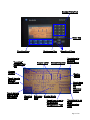
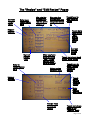
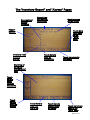
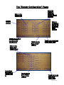
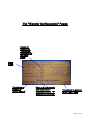
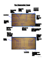
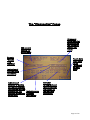
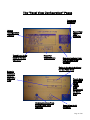
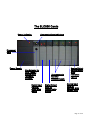
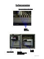
Allen Bradley PLC
OL-470 Series
Service Manual
Please note that our address and phone information has changed.
Please reference this page for updated contact information.
These manuals are obsolete and are provided only for their technical information, data and capacities.
Portions of these manuals detailing procedures or precautions in the operation, inspection, maintenance
and repair of the products may be inadequate, inaccurate, and/or incomplete and shouldn’t be relied
upon. Please contact the ACS Group for more current information about these manuals and their
warnings and precautions.
Parts and Service Department
The ACS Customer Service Group will provide your company with genuine OEM quality parts manufactured to engineering
design specifications, which will maximize your equipment’s performance and efficiency. To assist in expediting your phone
or fax order, please have the model and serial number of your unit when you contact us. A customer replacement parts list
is included in this manual for your convenience. ACS welcomes inquiries on all your parts needs and is dedicated to
providing excellent customer service.
For immediate assistance, please contact:
•
North, Central and South America, 8am – 5pm CST +1 (800) 483-3919 for drying, conveying, heating and cooling
and automation. For size reduction: +1 (800) 229-2919.
North America, emergencies after 5pm CST (847) 439-5855
North America email: [email protected]
•
Mexico, Central & South America
Email: [email protected]
•
Europe, Middle East & Africa +48 22 390 9720
Email: [email protected]
•
India +91 21 35329112
Email: [email protected]
•
Asia/Australia +86 512 8717 1919
Email: [email protected]
Sales and Contracting Department
Our products are sold by a worldwide network of independent sales representatives. Contact our Sales Department for the
name of the sales representative nearest you.
Let us install your system. The Contract Department offers any or all of these services: project planning; system packages
including drawings; equipment, labor, and construction materials; and union or non-union installations.
For assistance with your sales or system contracting needs please Call:
North, Central and South America +1 (262) 641-8600 or +1 (847) 273-7700 Monday–Friday, 8am–5pm CST
Europe/Middle East/Africa +48 22 390 9720
India +91 21 35329112
Asia/Australia +86 512 8717 1919
Facilities:
ACS offers facilities around the world to service you no matter where you are located. For more information, please visit us at
www.acscorporate.com
United States:
ACS Schaumburg – Corporate Offices
1100 E. Woodfield Road
Suite 588
Schaumburg, IL 60173
Phone: + 1 847 273 7700
Fax: + 1 847 273 7804
ACS New Berlin – Manufacturing Facility
th
2900 S. 160 Street
New Berlin, WI 53151
Phone : +1 262 641 8600
Fax: + 1 262 641 8653
Asia/Australia:
ACS Suzhou
109 Xingpu Road SIP
Suzhou, China 215126
Phone: + 86 8717 1919
Fax: +86 512 8717 1916
Europe/Middle East/Africa:
ACS Warsaw
Ul. Działkowa 115
02-234 Warszawa
Phone: + 48 22 390 9720
Fax: +48 22 390 9724
India
ACS India
Gat No. 191/1, Sandbhor Complex
Mhalunge, Chakan, Tal Khed,
Dist. Pune 410501, India
Phone: +91 21 35329112
Fax: + 91 20 40147576
Number Entry Pad
Enter Key
Function Keys
“Learning”
extrusion rate
box
Backspace Key
Hopper Level
Directional Keys
Recipe Setpoints
Hopper
Number
Recipe
Actuals
Touch here to
go to the
Alarms Page
Touch here to
Start or Stop
the Blender
Touch here to
go to the
Recipe Setup
Touch here
to go see
the
Inventory
Report
Blending
Rate
Extrusion Blender Mode
Rate
Touch here to go to
the Calibrate
&Diagnostics Page
Touch here to go
to the
Configuration
Page
Page 2 of 20
The “Recipe” and “Edit Recipe” Pages
Current
recipe
value
Enter new
recipe value
here
Min rate the
blender can
run the given
recipe at
Max rate the
blender can run
the given recipe
at
Hopper
Number
Touch here to
load a stored
recipe
Touch here
to go to the
“edit”
stored
recipe
page
Current
Recipe
Total
Enter in
recipe values
here
After you have
entered in the
“new” recipe
values, touch
here to accept
Enter recipe
Number here
Hopper
Number
Current
Recipe
Name
Touch here to go back
to the “Main” page
Touch here to
open a saved
recipe for
editing
Touch
here to
save the
recipe
Enter
Recipe
Name here
Recipe Total
of entered
recipe
Touch here to go
back to the
“Recipe” page
Page 3 of 20
The “Inventory Report” and “Alarms” Pages
Accumulated
Hopper
Inventory
Report time
and date for
inventories
Machine name
for the report
Hopper
Number
Touch here
to go back
to the
“Main”
page
Inventory Total
of entire
blender
Touch here to
clear all
inventories
Touch here to print
the report
Alarm log of
all alarms
with date and
time
Touch
here to
scroll
through
the alarms
Touch
here to
print the
alarms
Touch here to
clear the
alarm log
Touch here to
acknowledge
all alarms
Touch here to go
back to the
“Main” page
Page 4 of 20
The “Blender Configuration” Pages
Enter the
weight at
which the
hopper should
reload at
Enter in the
Hopper size
Hopper
Number
Enter in
the sample
size for the
weight per
count
learning
Touch here to go to
the Panel View
Configuration
Touch here to
go to “Setup
Page 2”
Enter in the
Mass Flow
hopper zones
Touch here
to go back to
“Setup Page
1”
Touch here to
go to “Setup
Page 3”
Touch here to go back
to the “Main” page
Touch here to go
back to the
“Main” page
Page 5 of 20
The “Blender Configuration” Pages
Touch here
to either
enable or
disable the
extruder
RPM
voltage
feedback
Enable or
disable the
“Auto Start”
feature
Enter the
maximum
extruder RPM at
10Volts
reference
Select
English or
Metric units
Enter the machine
name for the
Inventory Report
Touch here
to specify
either AC
or DC
Drives
Touch here
to go back
to the
“Main”
page
Touch here to
go back to
“Setup Page 2”
Touch here to go to
“Setup Page 4”
Enter in the
gearbox ratio
for each
hopper
Hopper
Number
Touch here
to go back
to “Setup
Page 3”
Touch here to
go back to
“Setup Page 5”
Touch here to go
back to the
“Main” page
Page 6 of 20
The “Blender Configuration” Pages
Enable or
disable the
“Shutdown”
procedure for
the given
alarm
Alarm
Name
Touch here to
go back to
“Setup Page 4”
Enter in the “Calibrate
and Diagnostics”
access password. “0”
disables this function.
Touch here to go back
to the “Main” page
Page 7 of 20
The “Diagnostics” Pages
Touch here to go
to the “Auger
Calibration” page
Touch here to go
to the “Load
Cell” calibration
page
Disable or Enable the
loading of the hoppers
Touch here
to go to the
“Check
Motors”
page
Touch here
to go back
to the
“Main”
page
Touch here to go to
the “Extruder
Calibration” page
Hopper
Number
Enter the
calibration
weight
size.
Touch here
once you
have emptied
the hopper
Touch here after
you place the
test weight on
the hopper
Touch here to go back
to the “Diagnostics
Main” page
Page 8 of 20
The “Diagnostics” Pages
Accumulated
Hopper
Inventory
Enter in the
hopper
number
Calculated
max rate for
auger
Instructions
Enter in the
calibration
sample size
Enter in
the
calibration
speed
Calculated
min rate for
auger
Accumulated
Weight for
calibration
Touch here to
begin the
calibration
Touch here to
abort the
calibration
Enter the
speed from 0100 percent
for the auger
Touch here to go back
to the “Diagnostics
Main” page
Touch here
to change
the mode
from
“Normal” to
“Test”
Hopper
Number
Instructions
Touch here to go
back to the
“Diagnostics Main”
page
Page 9 of 20
The “Diagnostics” Pages
30 second
buffer counter
for averaging
the extrusion
weight per
count
255 second
counter for
steady zone
Remote
“Steady
Flag”
Indicator
Touch here
to go back
to the
“Diagnosti
cs Main”
page
Indication of
extruder RPM
conditions
Indication of
whether or not the
current throughput
information is being
buffered for the
Instantaneous
extruder weight per extruder
count ratio
information
Extruder
throughput and
rpm values that
were used for
the last ratio
calibration
Page 10 of 20
The “Panel View Configuration” Pages
Language
Selection
Select
Configuration
Options
Touch here to go
back to Normal
Operation
Panel View
Fault
Indicator
Reset for
Video Screen
Communications from
PLC to Panel View
Indicator
Enter in the Node Address
for the Panel View
Enter in
the Baud
Rate for
the Panel
View
Touch here
to go back
to the
“Panel
View
Configurati
on Main”
page
Communications from
PLC to Panel View
indicator
Panel View fault
indicator
Page 11 of 20
The “Panel View Configuration” Page
Accumulated
Hopper
Inventory
Handshaking
selection for
printer
Print format
selection
Data
Package
Setup
Baud Rate for
Printer Port
Touch here to
go back to the
“Panel View
Configuration
Main” page
Touch here to enable or
disable the printer, it
must be disabled if you
are downloading to the
panel view
Page 12 of 20
The SLC500 Cards
Power Indicator
Communications Indicators
Processor
Card
Power Supply
Key Selector for
CPU “Mode”,
should be in
“Remote”
position.
Digital Input
Card for
auger prox
inputs
Thermocouple
Card for
Loadcell Inputs
Digital Output
Card for
loading valve
signals
Analog Output
card for auger
drive
reference
signals
Analog Input
Card for
Extruder RPM
voltage input
Page 13 of 20
The Panel connections
Connector to Blender Drive Panel
Loadcell
connectors
Panel View 550
Panel View
Communications (DF1)
and Power Cable
SLC 500
5/04 64k
Page 14 of 20
Downloading and Uploading to the SLC 500 PLC
Tools Needed: laptop or PC with “Rockwell Automation/ RSLogix 500” installed and
activated. When activating after you have installed the RSLogix 500 software you will
need to insert the “Token” disk that comes with the RSLogix 500 software. This disk is
“backed-up” on the server using a program called “WINDUPE”. The disk can only be
used on one computer (single license). For more information on installation see the
RSLogix 500 software package.
You will also need a standard straight thru serial cable (DB9 on each end) and a “Null”
modem converter that will plug into the cable and then to the SLC 500. The “Null”
modem converter can be made by getting 2 DB9 connectors and soldering pins 5-5, 2-3,
and 3-2.
COM Port
Laptop
Straight Thru Serial
Cable
SLC 500
Null Modem
RS232 Port
of SLC 500
Downloading and Uploading Steps
Step 1:
The first step is that you have to setup the communications drivers for
RSLinx. From the laptop run “Rockwell Software/RSLinx/RSLinx”. Then go under
“Communications”, then go to “Configure Drivers”. Delete all drivers listed under
“Configured Drivers” by highlighting the driver listed and the clicking “Delete” (you will
not be able to delete a “virtual” link driver). Now select “RS-232 DF1 Devices” under
“Available Drivers” and click “Add”. When the configuration screen appears click “Auto
Configure”, this will look for the SLC 500 through the cable link and will automatically
configure the driver. In the future if you change the Node Address of the SLC 500 you
will need to go back to this page and re-click the “Auto Configure” button. You can get
to this page by double-clicking the “RS-232 driver” listed under “Configured Drivers”.
Once the “Auto Configure” has been successfully completed then you will be able to
upload and download to the SLC 500. Remember to leave the RSLinx running.
Step 2:
The first step whenever you are working with a SLC 500 that does have a
program in it (at a customer’s site) is to upload and save the program that is currently in
the SLC 500. That way you can download this original program back to the SLC 500 in
case of a problem with the new software you intend to download. Before proceeding be
sure to go to the panel view and write down all of the configuration settings so that you
can reprogram the unit when you are done downloading. If prompted for a password on
the panel view, we use 2 passwords, “5413” and “3145348”.
To upload the existing program from the customer’s SLC 500 to your laptop first run
“Rockwell Software/RSLogix 500/RSLogix 500”. Once the program is running go under
“Comms” and select “Upload”. Follow the instructions. Once the upload is complete go
under “File” and save the project into a directory that you have made in WIN95.
Page 15 of 20
Downloading and Uploading to the SLC 500 PLC
Step 3: Whenever you are ready to download the new software, close the files that you
currently have on the RSLogix 500 program and then open the new files from wherever
you have stored them. You always want to open the file named “blend_4.RSS” or
“blend_8.RSS” found under “PLC Projects/AB OL Software/Standard”. Once the new
program is open, go under “Comms” and select “Download”. Follow the instructions.
After the program downloads you will be prompted “Put the PLC back into “RUN” mode”,
answer yes to this. This completes downloading and uploading to the SLC 500. Be sure
to reconfigure the SLC 500 blender setup parameters using the SLC 500. Then
recalibrate the load cells, and run an “auger calibration” for each hopper.
Downloading and Uploading to the Panel View
Tools Needed: Laptop with both RSLogix installed as described before and “Panel
Builder” installed. Panel Builder software does not use a “Token” disk to protect against
multiple installations (however you are legally only allowed to install this software to one
computer). For more information on installation see the Panel Builder software package.
You will also need one standard straight thru serial cable to connect between the com
port on the laptop and the RS-232 port of the Panel View.
Laptop
COM Port
Straight Thru Serial
Cable
Panel View
RS232 Port of
Panel View
Step 1:
The first step is that you have to setup the communications drivers for
RSLinx. From the laptop run “Rockwell Software/RSLinx/RSLinx”. Then go under
“Communications”, then go to “Configure Drivers”. Delete all drivers listed under
“Configured Drivers” by highlighting the driver listed and the clicking “Delete” (you will
not be able to delete a “virtual” link driver). The Panel Builder software uses it’s own DF1
driver and therefore you cannot have any drivers configured under the RSLinx software
or it won’t work. Be sure though to leave the RSLinx software running.
Step 2:
The Panel View software program for the Allen Bradley OL-470 has the
printer port enabled in the software. This allows the customer to print reports from this
port. However, whenever you are uploading or downloading you must use this port for
communications and not printing. To set this up you will need to go to the “Panel View
Configuration” page, then “Printer Setup”, and then disable the printer port under “Port
Mode”. Once you have done this touch “Exit” and the touch “Run Mode” (this places the
Panel View back into normal operation mode). To get to the “Panel View Configuration”
page go to the Panel View and hold both the left and right arrows on the keypad. This will
bring up the configuration page for the Panel View System.
Page 16 of 20
Downloading and Uploading to the Panel View
Step 3:
If the existing Panel View already is running software (customer’s site), then
you will first need to upload and save this to a directory of your choice. That way if you
have any problems with the new software then you will be able to download the old
software back into the unit. If you are only changing the Panel View software and not the
SLC 500 software then you do not have to right down all of the “Setup” parameters for
the blender. These parameters will automatically be loaded into the panel view from the
SLC 500 once you have completed the download. To upload the existing software from
the panel view to your laptop first run “Panel Builder/Panel Builder”. Do not run the
“Application file Transfer Utility!!!!”. Once Panel Builder is running go to “Application”
and select “Upload”. When the upload is complete save the file onto the laptop into the
directory of your choice. Typically label it “Onsite “date”” and name the folder the
customer’s name. After this is done you will be ready to download the new software to
the panel view.
Step 4:
Close any files that are currently open in panel builder and then open the
new software file (“4_comp.pba” or “8_comp.pba”, that is found under “PLC Projects/ABOL Software/Standard”). WHENEVER PROMPTED SELECT “REPLACE ALL” AND “ADD
ALL”. Once the file is open then go under “Applications” and select “Download”. Follow
the Instructions. When this is complete the Panel View will reboot automatically and
should come up in normal operation mode. This completes the uploading and
downloading of Panel View Software.
Page 17 of 20
Remote DH+ Addressing
Purpose
This allows an OEM to connect a DH+ link to the AB OL blenders and communicate data
and set points. The blender can remotely be controlled as the OEM designs his custom
screens. The following are the AB DH+ addressing for all available data. The Node
Address for the SLC500 defaults to 10, the Node Address for the PanelViews defaults to
11. To change these addresses go online to the unit and modify these settings at the
unit. The original code that comes from AEC/HydReclaim will not be set up for the OEM’s
custom addresses and must be modified by the OEM or customer.
Addresses and Explanation of use
Machine Name — ST99:0.2 — Read/Write — Name of machine (example: “Ext 1”)
Blender Units — N11:0/0 — Read/Write — Maintained — 0 is metric, 1 is standard
Blender Mode — N11:2/0 — Read/Write — Maintained — 0 is set when the blender is
stopped, 1 is set when the blender is running.
Blender Alarm Active — 0:2/15 — Read Only — 0 is no alarms, 1 is alarm active
Acknowledge and Clear all alarms — N11:31 — Read Only — write a momentary 1 to
clear all alarms and turn off the alarm horn, this will delete the alarms so you should read
each alarm bit to determine what the alarm is before giving the option to clear the
alarms.
Hopper 1
Reload too long N11:11/0
Out of Material
N11:9/0
No Material Flow N11:10/0
Scale Exceeded N11:6/1
Loadcell Failure N11:12/0
Motor Failure
N11:13/0
Hopper 2
N11:11/1
N11:9/1
N11:10/1
N11:6/2
N11:12/1
N11:13/1
Hopper 3
N11:11/2
N11:9/2
N11:10/2
N11:6/3
N11:12/2
N11:13/2
Hopper 4
N11:11/3
N11:9/3
N11:10/3
N11:6/4
N11:12/3
N11:13/3
Mass Flow Hopper
N/A
N/A
N/A
N11:6/9
N11:12/8
N/A
Loading Enabled — B3:3/6 — Read/Write — Maintained — 0 is set to disable the loading
of the weigh hoppers, 1 is set to enable the loading of the hoppers.
Hopper Data — Read Only, see below for addresses
Hopper is Loading
Hopper Weight
Hopper % Full
Motor Speed in %
Hopper 1
N10:11/0
F9:1
F9:221
F9:21
Hopper 2
N10:11/1
F9:2
F9:222
F9:22
Hopper 3
N10:11/2
F9:3
F9:223
F9:23
Hopper 4
N10:11/3
F9:4
F9:224
F9:24
Mass Flow
N/A
F9:10
F9:41
N/A
Page 18 of 20
Remote DH+ Addressing
Blender Total Rate — F9:90 — Read Only — total rate that all the augers are running at,
this is not the extrusion rate
Extrusion Rate — F25:1 — Read Only — the rate at which the extruder is taking away the
blended material
Stable Extrusion Flag — B3:3/1 — Read Only — this flag is set once the blender
accurately learns the extrusion rate. This flag should be read before using the
“Extrusion Rate” data described above, if this flag is set to “0” then the OEM should use
previous relationships for extrusion rate per RPM. This relationship can be developed
using the “Stable Extrusion Flag”, “Extrusion Rate”, and the current extruder RPM. Once
this relationship has been developed it should be stored by the OEM.
Extruder RPM — F9:29 — Read Only — available only if “Extruder RPM Voltage
Reference” is enabled (the customer supplies the blender with a 0-10 Volt/4-20 mA signal
that references drive speed, usually this can be taken from the drive itself and is
recommended if the customer plans to use the “Extrusion Rate” information for extrusion
control calculations.
Extruder RPM Voltage Reference — N11:0/1 — Read/Write — Maintained — when set to 1
this instructs the blender to use a 0-10V/4-20 mA signal to calculate extruder RPM. This
is then used by the blender to develop and buffer the relationship between extrusion rate
and extruder RPM. This should always be used when the customer is planning on using
the “Extrusion Rate” information for extrusion control calculations.
Maximum Extruder RPM — F9:180 — Read/Write — only used if the “Extruder RPM
Voltage Reference” is enabled, use this to adjust the displayed “Extruder RPM” value of
the blender. If the displayed RPM is too low then increase this value, if it’s too high then
decrease this value.
User Password — N11:35 — Read/Write — only used when the operator is accessing the
“Calibration/Diagnostics” page from the Panel View. If set to “0” then no password will
be necessary for the operator to calibrate the blender from the Panel View.
Handling the blender recipe — the current blender recipe that is running in the blender
can be read without any special procedure. In order for the OEM to properly change the
recipe remotely they will need to complete a procedure in the proper order and examine
certain addresses to ensure that the recipe that the operator enters is accepted. This
procedure is already handled at the Panel View, but if you wish for the operators to be
able to enter in the blender recipes at the OEM screen then this procedure must be
followed.
Reading the current running recipe (Read Only!)
Hopper 1
Hopper 2
Hopper 3
Hopper 4
Set %
F9:91
F9:92
F9:93
F9:94
Actual %
F9:171
F9:172
F9:173
F9:174
Lowest Rate at which the blender can run the current recipe: F9:40
Highest Rate at which the blender can run the current recipe: F9:39
Page 19 of 20
Remote DH+ Addressing
Writing the current running recipe
Step 1: Write all new recipe set percentages to the “new” recipe location
Hopper 1– F101:0, Hopper 2– F102:0, Hopper 3– F103:0, Hopper 4– F104:0
Step 2: (optional) Read back in these same addresses to ensure that they made it to the
correct place, this can be done simply by displaying in a different box these values for
the operator to see.
Step 3: Read N11:2/15 to ensure that the recipe adds to “100”, this will be set if the new
recipe does not equal 100, and therefore the new recipe will not be accepted until it
does. Show the operators a message for this.
Step 4: Read B3:3/4 to see if the “New” recipe is ready for acceptance. Once this bit is
set then give the operators a button to “Accept New Recipe”. If this bit is not set the
operator should not be able to accept the new recipe.
Step 5: Write a “1” to B3:8/0 to accept and transfer the new recipe.
Step 6: Read B3:4/0 to see if the blender cannot run the recipe that you have
transferred. If this bit is set then read the following addresses to determine why the
recipe was not transferred.
Cannot Achieve Low Rate
Cannot Achieve High Rate
Hopper 1
N11:8/0
N11:7/0
Hopper 2
N11:8/1
N11:7/1
Hopper 3
N11:8/2
N11:7/2
Hopper 4
N11:8/3
N11:7/3
Step 7: Be sure to continuously display the “Set %” as described before under “Hopper
Data”. This will give the operators an understanding that the “New” recipe that they
have entered was accepted and transferred.
The reason that a given recipe cannot be ran by the blender is that the blender is
designed to run each motor within its designed range (3-98 % of motor speed). This
ensures overall blending accuracy and performance, but is generally the most difficult
topic for someone new to gravimetrical blending to comprehend. Each hopper has a
minimum throughput and a maximum throughput that is continuously updated. The
following data in conjunction with the given recipe is used to calculate the “Blender Min
Rate” and the “Blender Max Rate”. These values are related to material density, gear
box ratio of the hopper, and the auger size of the hopper. If a different range is desired
contact AEC/HydReclaim for help.
To examine the range for a given hopper first write the desired hopper number to N11:4
Then the minimum throughput for that hopper can be read from F9:150
Also the maximum throughput for that hopper can be read from F9:140
This concludes all remotely accessible DH+ addresses and integration
Page 20 of 20