1
TopView 3
Remote and Visualisation Software for TOPAX controllers
EN
01
Installation and
User Manual
Read this operating manual before using the equipment.
To be retained for future reference.
Table of Contents
1. General........................................................................................................................................................................3
1.1 TopView Mini...................................................................................................................................................... 3
1.2 TopView Standard............................................................................................................................................... 3
2. Installing TopView.......................................................................................................................................................4
2.1 System prerequisites.......................................................................................................................................... 4
2.2 Initial installation of TopView Mini......................................................................................................................... 4
2.3 Initial installation of TopView Standard.................................................................................................................. 4
2.4 Installing the dongle manually (with TopView Standard)......................................................................................... 5
2.5 Upgrading an installed version to TopView 3 Mini.................................................................................................. 6
2.6 Upgrading an installation of TopView 3 Standard................................................................................................... 6
3. Installing the RS-485 bus network............................................................................................................................7
3.1 Electrical wiring.................................................................................................................................................. 8
3.2 Crossbar switch for digital on/off switches........................................................................................................... 8
4. Operation and configuration of TopView...................................................................................................................9
4.1 General.............................................................................................................................................................. 9
4.2 Configuring devices in the RS-485 bus network................................................................................................... 9
4.3 Selecting the computer port for the RS-485 bus network.................................................................................... 10
4.4 Assigning controller names............................................................................................................................... 11
4.5 Configuring the connected controllers................................................................................................................ 12
4.6 Configuring digital inputs and outputs with a connected crossbar switch.............................................................. 13
4.6 Configuring a password.................................................................................................................................... 13
5. Displaying the measured data.................................................................................................................................14
5.1 Views............................................................................................................................................................... 14
5.2 Bars view......................................................................................................................................................... 15
5.3 Graph view....................................................................................................................................................... 16
5.4 Overview.......................................................................................................................................................... 17
6 Journal.......................................................................................................................................................................18
7 Logging all data received..........................................................................................................................................19
8. Alarms.......................................................................................................................................................................19
9. Other functions.........................................................................................................................................................20
9.1 Reading and printing controller parameters........................................................................................................ 20
9.2 System information........................................................................................................................................... 20
9.3 Remote access to TopView................................................................................................................................ 20
9.4 Crossbar switch................................................................................................................................................ 21
10. Revision...................................................................................................................................................................22
11. Index........................................................................................................................................................................23
| TopView 3 | Table of Contents
1. General
TopView PC software visualises and stores data for measured values in real time (e.g. hygiene parameters for
swimming pools) for up to 15 TOPAX® controllers in a network. It can also be used to display or remotely configure settings on the controllers. Display of up to eight digital inputs and operation of up to eight digital outputs
are possible. For applications in public swimming pools, it can also be used to keep a daily journal.
The computer on which the TopView software is installed is connected to the controllers or digital inputs/outputs via a serial RS-485 bus network (MODBUS protocol).
IMPORTANT!
To connect the computer to the RS-485 bus network, a USB or RS-232 (serial PC port) connector converter is
used for the RS-485 (A/N 44300102 or A/N 44300101 of manufacturer). These are not included in the scope
of delivery for the TopView software.
TopView starts in two different modes – Standard mode, or Mini mode – depending on user requirements and
which licences you have purchased. The installation program for TopView is free-of-charge (for both modes)
and can either be downloaded from the manufacturer's website or is available as CD from the manufacturer. If
a licence has not been purchased, the software will start in Mini mode with a reduced scope of functions.
1.1 TopView Mini
In Mini mode, TopView provides visualisation of all measured values, a representation of these as a graph over
time and displays all internal and external alarms (e.g. low sample water level). Configuration of controllers,
their parameters and digital inputs/outputs or storage of data for measured values in daily logs are not available.
"TopView Mini“ appears at the top of the window in Mini mode.
1.2 TopView Standard
All functions available in Mini mode are also available in Standard mode. In addition, data for all measured
values is saved in daily logs and can be exported. Controllers, their parameters and digital inputs/outputs can
all be configured. A DIN-confirm log for public swimming pools can also be maintained.
TopView enables remote configuration of the following controller parameters:
• Setpoints
• Controller characteristics
• Alarm values
• Max. and min. values for representation as a graph
• Carrying out of shock chlorination
Installation of software, the installation program and TopView are the same with both modes. On purchasing a
Standard licence, users will also receive copy protection hardware (a dongle). This will recognise the software
automatically after it has been started and enable Standard mode with its extended scope of functions.
When the software is started in Standard mode, "TopView“ will appear at the top of the window.
General | TopView 3 | 2. Installing TopView
2.1 System prerequisites
• At least 50 MB of memory space available on hard drive
• CD drive (TopView Standard only) or Internet access
• Serial port or USB port
• Parallel or USB port for copy protection hardware (Dongle) (TopView Standard only)
• Windows XP operating system (Service Pack 2 or later) or Windows Vista operating system (Service Pack
1 or later)
IMPORTANT!
Deactivate all screensavers as these disturb how TopView operates!
ATTENTION!
To install TopView, you must have administrator rights on your PC.
2.2 Initial installation of TopView Mini
The installer program is available as a download or on a CD.
Installer as a download
• Download the installer program from the manufacturer's website.
• Open the file "inst_tv3.zip“ and unpack its contents.
• Start the program inst_tv3.exe.
Installer program on a TopView CD
• Insert the TopView CD.
• The CD will start automatically.
If autorun does not commence, double-click on the file D://start.htm to start the CD.
• Your standard browser will now open up.
• Click "Installer Topview 3 (Multi Language)“.
Installation of download or from CD (continued)
• Choose the desired language.
• Read through the licence agreements thoroughly and confirm you accept these.
• Select the desired options: Autorun, quick launch bar. Click OK to confirm.
• Specify the installation location.
• Start the installation.
2.3 Initial installation of TopView Standard
To use TopView in Standard mode, the software needs to be used with the purchased copy protection hardware
(Dongle) (A/N 41900012 for TopView 3 Standard with dongle for parallel port, A/N 41900011 for TopView 3
standard with dongle for USB port).
IMPORTANT!
Do not start installing TopView until you have attached the dongle to your PC.
•
•
•
•
•
•
•
•
•
•
Insert the copy protection hardware (Dongle)
into the parallel port or USB port on your PC.
Insert the TopView CD.
The CD will start automatically.
If autorun does not commence, double-click on the file D://start.htm to start the CD.
Your standard browser will now open up.
Click the icon for "Installer Topview 3 (Multi Language)“.
Choose the desired language.
Select the desired options: Autorun, quick launch bar. Click OK to confirm.
Read through the licence agreements thoroughly and confirm you accept these.
Specify the installation location.
Start the installation.
| TopView 3 | Installing TopView
ATTENTION!
When installing TopView, the drivers required for the copy protection hardware (dongle) for TopView Standard
will only be installed if you have inserted the dongle at the time of installation. If the dongle is not detected, you
will need to install the drivers manually.
2.4 Installing the dongle manually (with TopView Standard)
If the dongle could not be recognised during installation (despite dongle and computer restart, TopView continues to start as TopView Mini with restricted functions), you will have to install the dongle drivers manually:
• Close any programs that are running.
• Insert the TopView CD.
• Close the installation environment, which will start up automatically (browser).
• Open Windows Explorer.
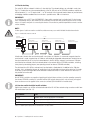
• On the CD, start the “CbSetup.exe” in the directory D://Drivers/CbSetup”.
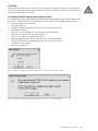
• Select "Install“ and click "OK" to confirm (see Fig. 2.1)
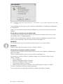
• Click "Yes“ to confirm the installation (see Fig. 2.2)
• Choose your dongle version "CRYPTO-BOX Versa (LPT)“ (for parallel dongle)
or "CRYPTO-BOX USB“ (for USB Dongle) and click "OK“ to confirm (see Fig. 2.3)
• The drivers are now installed.
• Now restart the computer.
Fig. 2.1 Installing the dongle drivers manually. CbSetup.exe - Select Mode - Click "OK" to confirm
Fig. 2.2 Installing the dongle drivers manually. CbSetup.exe - Click "Yes“ to confirm installation
Installing TopView | TopView 3 | Fig. 2.3 Installing the dongle drivers manually. CbSetup.exe - Select hardware - Select according to dongle type and click "OK"
to confirm
To test the dongle connection, you can use the application "MarxProbe.exe“ in the directory D://Dongleprobe/
on the TopView-CD.
If there is still no connection between computer and dongle, please contact the manufacturer or their representatives.
2.5 Upgrading an installed version to TopView 3 Mini
If you already have the TopView 2 Mini or TopView 2 Standard version installed on your PC, you can simply
install TopView 3 Mini in an additional directory.
TopView 3 Mini can read daily logs created with a version of TopView 2 Standard but cannot write to them.
To do this, close all applications and carry out the installation as described in 2.2.
IMPORTANT!
Two TopView programs may not run simultaneously where these access a common interface.
IMPORTANT!
TopView 3 will not detect the dongle for a version of TopView 2 Standard.
2.6 Upgrading an installation of TopView 3 Standard
If you have a version of TopView 2 Mini installed on your PC, you can install a TopView 3 Standard version
without any problems.
To do this, close all applications and carry out the installation as described in 2.3.
If you already have a version of TopView 2 Standard installed on your PC, proceed as follows to install
TopView 3 Standard:
• Close all applications.
• Remove the old dongle for TopView 2 Standard.
• Attach the new dongle for TopView 3 Standard.
• Carry out the installation as in section 2.3.
• Select the directory for TopView 2 Standard as the installation location for TopView 3 Standard.
In TopView 3 Standard, you will need to reenter the controllers.
You can read and write to all daily logs from TopView 2 Standard using TopView 3 Standard.
| TopView 3 | Installing TopView
3. Installing the RS-485 bus network
Simultaneous communication of a PC connected with up to 15 TOPAX® controllers and an external crossbar
switch for digital inputs/outputs is possible via the RS-485 bus network (Modbus protocol). All TOPAX® controllers may optionally be equipped in the factory with a serial RS-485 port. A unique network address must be
assigned to each TOPAX® controller in the relevant network for differentiation. The connected PC requires an
interface converter (see Section 1) for connection to the RS-485 bus network.
IMPORTANT!
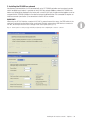
When using an RS-232 interface converter for RS-485, to prevent transmission errors, the FIFO buffer for the
serial port used must be deactivated in the control panel. Similarly, when using a USB interface converter for
RS-485, the USB port must be set accordingly in the control panel (see Fig. 3.1).
Fig. 3.1: Control panel for serial port (top) and USB port (bottom) when configuring the connector converter.
Installing the RS-485 bus network | TopView 3 | 3.1 Electrical wiring
The serial RS-485 bus network is fed via a 2-wire data line. The network devices are switched in series (see
Fig 3.2). The data line must be connected directly at the RS-485 ports of the TOPAX® controllers and the connector converter ("+“ or "A" terminal and "-“ or "B“ terminal). Use of separate terminal boxes or junction boxes
for bridging should be avoided. Data transmission is possible across 100 m at maximum.
IMPORTANT!
As a data line, use a KAT.5, type 2X2XAWG24/1 (Lapp cable) computer lead or a better lead. For electromagnetic compatibility reasons, the shield must be connected on both sides with protective ground across a wide
area so it conducts well prior to connecting the devices. Ensure that no potential equalization currents can flow
via the shielding.
NOTE!
If other types of cable are used as a data line, data errors may occur which disturb the data transmission.
Fig. 3.2: Standard RS-485 bus network
Computer
(TopView Software)
1...15 x
Schaltereinheit
Digitale Ein-/Ausgänge
A
TOPAX Regler
(DX, DE, L, LF, N, NT)
B
B
A
TOPAX Regler
(DX, DE, L, LF, N, NT)
A
B
TOPAX Regler
(DX, DE, L, LF, N, NT)
Schnittstellenkonverter
At both ends, the data line must terminate with a resistance of 120 ohms. If a connector converter from the
manufacturer is used, a load resistor of 120 ohms will already be integrated and connected. The data line can
then be started with the PC as the first network device in the RS-485 bus network. A resistance of 120 ohm
must likewise be switched at the final network device in the network. With all TOPAX® controllers, switching
takes place by connecting jumpers (see operating manual for relevant TOPAX® controller).
The data lead of an RS-485 bus network must be attached to a fixed potential. In addition to the 120 ohm
resistors, this is achieved by the one-off application of pull-up/pull-down resistance in the data line. This leads
to the bus system returning to idle current whenever no data transmitter is active. Without this measure, it is
not possible to transfer data.
IMPORTANT!
Not all TOPAX controllers are capable of applying pull-up/pull-down resistance. (see the operating manual for
the relevant TOPAX® controller). If controllers without pull-up/pull-down resistors only are used, pull-up/pulldown resistance must be applied at the connector converter (A/N 44300102 of manufacturer).
3.2 Crossbar switch for digital on/off switches
Digital inputs/outputs can also be activated and read via the RS-485 bus network using a crossbar switch from
the manufacturer (see Tab. 3.1).
Part number
Part
78155
Modbus basic unit for connection of assemblies
78156
Digital input assembly (DC 24)
78157
Digital output assembly (potential-free relay outputs)
Table 3.1: Digital inputs/output parts for manufacturer's crossbar switch
| TopView 3 | Installing the RS-485 bus network
4. Operation and configuration of TopView
4.1 General
TopView has been developed according to the Windows Interface Guidelines for Software Design and makes
use of Windows technology.
The software is operated via the menu structure using mouse or keyboard. By pressing the "Alt“ (Alternate)
key, a letter in each menu item/sub-menu item will be underscored (see Fig. 4.1). You can use this letter to
open the menu item and can navigate through the menu using the arrow keys. To execute a menu command,
press the "Enter" key. To exit a menu, press the "Esc“ (Escape) key .
Example: To go to the sub-menu entitled "Controller name…“, use the shortcut "Alt“+“k“+“r“.
Fig. 4.1: Menu tree for TopView Standard
Each time the program is started, TopView will open in the view you were using when you last exited it. When
you first start TopView after installation, a window is opened with an "Overview" showing a table of the controllers found in the network and the measured values that have been read. Since no network devices are yet
configured, the "Demo" virtual controller will appear with random values (see Fig. 4.2).
Using the "View" menu, you can display measured values in various ways within the same window . To display
two or more windows at the same time, you can open up other windows in the "Windows" menu and then,
using the "View" menu, display the measured values as a graph, as bars or a table.
4.2 Configuring devices in the RS-485 bus network
All settings required to operate TopView are made in the Configuration menu.
After successfully installing the RS-485 bus network and the electrical wiring, the first step is for you to enter
the network devices (controllers) in TopView. You need to:
• enter the PC port for the connector converter (see 4.3)
• enter the network addresses for the connected controllers (see 4.4)
• allocate a user-defined name for each connected controller (see 4.4).
IMPORTANT!
You set the network address on the TOPAX controller (see relevant operating manual).
Each address may only be assigned once in a RS-485 bus network.
Operation and configuration of TopView | TopView 3 | Fig. 4.2: Start window after initial installation
4.3 Selecting the computer port for the RS-485 bus network
• Go to Configuration/Interface…
• Select the port at which the connector converter for the RS-485 bus network is located. Click "OK“ to
confirm your entries (see Fig. 4.3)
Fig. 4.3: Selecting the port for the connector converter
INFO!
The serial port on the PC is COM1 or COM2 depending on the number of ports available. The USB port simulates a serial interface COM x. You will find this under "System" on the Microsoft Windows Control Panel.
10 | TopView 3 | Operation and configuration of TopView
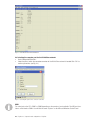
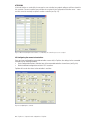
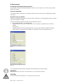
4.4 Assigning controller names
• Go to Configuration/Controller name…
• Delete the entries for the demo controller.
• Enter the network addresses for the connected controller in each line.
• Enter a desired name for each controller comprising no more than 12 characters.
• Click "OK" or "Apply" to confirm your entries.
• When TopView queries the controller in the network, as indicated by the rotating arrow, the serial number
and type of controller will be detected and displayed automatically.
Fig. 4.4: Setting the names for the connected controllers
The network addresses are scanned by TopView in turn, as indicated by the rotating arrow. If the serial number
and type is not entered automatically when scanning the device, data transmission has not taken place. In such
cases, you need to check the connection and configuration for the port.
ATTENTION!
Controllers are only allocated if you have selected Configuration/Controller name… and the window has
opened. For this reason, you should keep the window open until all connected controllers have been detected
correctly.
ATTENTION!
10 may not be assigned as a network address.
NOTE!
If a connected controller is switched off and this is not operated in the network for a longer period of time,
the name and network number should be deleted to ensure TopView operates without any problems and the
network load is reduced.
Operation and configuration of TopView | TopView 3 | 11
ATTENTION!
If the total chlorine or conductivity is measured on one controller, two network addresses will be assigned for
this controller. The next controller space will then be occupied in the Configuration/Controller name… menu
and this cannot be manually assigned to another controller (see Fig. 4.5).
Fig. 4.5: When measuring the total chlorine or conductivity, two controller spaces are occupied.
4.5 Configuring the connected controllers
Once you have configured the connected controllers successfully in TopView, the settings for the connected
controller can be accessed remotely.
• Go to Configuration/Devices and select one of the connected controllers shown there (see Fig. 4.6).
• Make the desired configuration and click "OK" to confirm.
TopView will transfer the values to the controller in real time.
Fig. 4.6: Configuring the controller
12 | TopView 3 | Operation and configuration of TopView
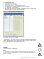
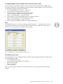
4.6 Configuring digital inputs and outputs with a connected crossbar switch
A crossbar switch can be connected in the RS-485 bus network for output and notification of digital statuses.
Up to eight inputs/outputs can be configured, switched or notified. The network address for the crossbar switch
is permanently assigned and need not be configured.
• Go to Configuration/Inputs and Outputs… (see Fig. 4.7).
• Insert a checkmark to activate the crossbar switch.
• Enter the names for the digital inputs in the left-hand column.
A circle will notify you about the state received for the input:
yellow = input switched, grey = input not switched.
• Enter the names for the switchable digital outputs in the right-hand column.
A box will notify you about the state transmitted for the output:
yellow = output switched, grey = output not switched.
• Switch the outputs accordingly by clicking on the corresponding boxes.
INFO!
In TopView Mini mode, you cannot select Configuration/Inputs and Outputs… In Standard mode, a check is
made following activation of the crossbar switch during configuration to see whether the crossbar switch is
present. If it is not connected, this will trigger an alarm message.
Fig. 4.7: Configuring the crossbar switch (TopView Standard only)
4.6 Configuring a password
Password protection has been integrated to protect settings in TopView. Following installation of TopView, there
is no preconfigured password.
• Go to Configuration/Password…
• Enter the old password (except on initial installation).
• Enter the new password.
• Enter it a second time.
• Click OK to confirm.
Once you have entered a password, it will not be possible to make any more changes to TopView without
entering it.
Operation and configuration of TopView | TopView 3 | 13
5. Displaying the measured data
Once configuration has been carried out successfully, measured data for the controllers, any alarms plus the
values for the external digital inputs/outputs of the crossbar switch will be transferred to TopView.
The following are transferred:
• actual values for all activated channels
• setpoints W
• controller output values Y
• alarms and
• serial number
of the device.
5.1 Views
All measured values are shown in black. Should a measured value deviate from the setpoint set in the controller by 20% (based on the display value set), this measured value will appear red in all views.
If the measured value is less than or greater than the alarm limits set in the controller, the colour of the measured value will also change to red and an alarm message will appear.
ATTENTION!
If a measured value changes its colour, this means it deviates from the setpoint. If an alarm message also
appears, it is less than or greater than the alarm limits. The alarm message will only disappear when the fault
has been rectified.
You can toggle between the "Overview“, "Bar“ and "Graph“ views (see Fig. 5.1).
Fig. 5.1: Various views arranged side-by-side.
14 | TopView 3 | Displaying the measured data
The first time TopView is started following installation, the Overview window will open up showing you the
configured controllers and their measured data in table form.
• Open another window by going to Window/New window.
• Change to Bars view by going to View/Bar.
All measured values for all configured controllers will be shown side-by-side as bars.
If you enlarge the window, the bars view will be enlarged too.
• Open another window by going to Window/New window.
• Go to View/Graphs and select a controller from the list, then change to the graph
view of measured values over time.
5.2 Bars view
In the Bars view, all connected controllers and all measuring inputs configured for the controllers are shown
simultaneously as horizontal coloured bars. Setpoints are indicated as vertical lines. With controlled measured
values, the state of the controlled actuator is shown under the bar for the measured value (see Fig. 5.2 and
Fig. 5.3). The controllers are shown under or next to one another in groups of two, six or nine depending on the
current window width.
Fig. 5.2: Bars view for the measured values of a controller
Fig. 5.3: Bar view for the measured values of two controllers with all measurable values
Displaying the measured data | TopView 3 | 15
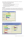
5.3 Graph view
In the Graph view, all configured measuring inputs are shown simultaneously against time as coloured representations. Setpoints are shown as a horizontal line. All measured values are be shown or hidden individually by
inserting the relevant checkmark next to the measured value. If one measured value only is shown, the Y axis
of the graph will appear with the measuring range scale for the individual measured value.
The current measured values are shown in large and in colour in the left-hand column. The limit values
assigned to the relevant controller and measured value are shown under Configuration/Devices in brackets.
Maximum and minimum values reached during the day are shown under the current measured value in black
(see Fig. 5.3).
The alarm messages appear at the bottom edge of the window.
The upper and lower limit for each measured value is determined via the limit value entered in the controller
(recorder output values 0/4-20 mA).
Fig. 5.3: Graph view for the measured values of a controller
Zoom function
The time axis of the graph allows several time intervals for enlarging or reducing the display: 2, 4, 8 or 24
hour intervals are possible. To change between these intervals, go to View/Zoom. You can move within the
graph by dragging with the mouse and using the arrow keys.
Print function
You can print the current view of the graph by going to File/Print Current View…
16 | TopView 3 | Displaying the measured data
Colours
In the Graph and Bars views, fixed colours are assigned to the measured values:
Colour
Yellow
Green
Dark blue
Orange
Brown
Light blue
Dark yellow
Purple
Measured value
Free chlorine/chlorine
dioxide
pH value
Redox value
Temperature
Combined chlorine
Conductivity
Total chlorine
Salt content
Table 5.1: Colour assignments in the views
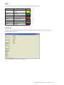
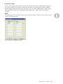
5.4 Overview
The overview shows all connected controllers and their measured values, setpoints and alarm values in real
time as a table (see Fig. 5.4).
Fig. 5.4: Overview of measured values for all controllers
Displaying the measured data | TopView 3 | 17
6 Journal
By going to the "Journal“ menu, you can keep a daily journal (e.g. for a swimming pool) in accordance with
legal requirements. Forms are provided for the entire swimming baths and for an individual swimming pool (see
Fig 6.1 and 6.2)
Fig. 6.1: Form for the entire swimming baths
Fig. 6.2: Form for an individual swimming pool.
18 | TopView 3 | Journal
7 Logging all data received
TopView Standard automatically generates log files with all data recorded in real time for all connected controllers. The files are saved at 23.59 each day and stored according to the naming convention: [Year]_[Month]_
[Day].tv2 You can create the current daily log by going to "File/Save to Log File" at any time.
Go to File/Open Log File… to open and display existing log files (*.tv2) in the Overview or Graph view. Data for
further processing can also be stored as a spreadsheet or in a text file.
To print all parameters, the log file must be open and its overview window selected. To print the current day,
you need to save the log file and then open it.
8. Alarms
Should a connected controller report an alarm or if the configured crossbar switch can no longer be accessed
via the network, TopView will trigger an alarm. A new window will then appear in which cause for the alarm will
be shown.
IMPORTANT!
The alarm window cannot be closed until the reason for the alarm has been rectified.
Logging all data received | TopView 3 | 19
9. Other functions
9.1 Reading and printing controller parameters
All parameters set for the connected controller are shown in the "Parameters" menu. These can be printed
without any changes.
9.2 System information
All system messages, information on the TopView software and the manufacturer can be displayed using the
"Info" menu.
9.3 Remote access to TopView
TopView can forward the information from the RS-485 bus network via an existing Ethernet network to another
PC on which TopView is installed.
To do this, the interface settings in TopView must be adjusted on both PCs.
• Go to Configuration/Port… on both computers.
• (Computer with RS-485) Select "TopView Server" on the computer connected with the RS-485 bus
network
(see Fig. 9.1)
• (Computer without RS-485) On the computer that is to access the RS-485 bus network via Ethernet,
select "Ethernet“ and enter the TCP/IP address for the other PC in the blank field (see Fig. 9.2).
Fig. 9.1:
Fig.: 9.2:
You will thereafter be able to display and operate the network devices on both computers.
IMPORTANT!
Only one server/client connection is possible with access via the Ethernet network.
ATTENTION!
Data for TOPAX® DE and TOPAX® L is not transferred in the network.
20 | TopView 3 | Other functions
9.4 Crossbar switch
As well as the controllers, you can control and read the crossbar switch with up to eight digital inputs/outputs
that can be installed in the RS-485 bus network with the mouse via the View/Inputs and Outputs window.
By clicking the grey/yellow rectangles next to the outputs, you can switch the digital outputs. "Yellow" means
switched. Switching of the inputs is indicated by grey or yellow circles. "Yellow“ means that the input is
switched.
NOTE!
These digital inputs do not constitute alarms for the connected controllers. Alarms for the controllers are only
shown in the "Overview" view.
Fig. 9.3: Crossbar switch digital inputs/outputs
Other functions | TopView 3 | 21
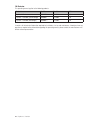
10. Revision
This operating manual applies to the following products:
Product
Part No.
Revision
Software
TopView 3 Mini
41900010
10.2008
3.0
TopView 3 Standard (parallel dongle)
41900011
10.2008
3.0
TopView 3 Standard (USB dongle)
41900012
10.2008
3.0
It contains all the technical information required for installation, start-up and maintenance. Should you have any
questions or require further information regarding this operating manual, please contact the manufacturer or its
official national representative.
22 | TopView 3 | Revision
11. Index
A
Alarms..........................................................................19
Alarm messages............................................................16
Displaying the measurement data...................................14
B
Bars view......................................................................15
Journal..........................................................................18
Screensavers...................................................................4
C
COM1 or COM2.............................................................10
CRYPTO-BOX...................................................................5
D
Data line..........................................................................8
Digital inputs/outputs.......................................................8
Dongle............................................................................4
Printing.........................................................................20
Print function.................................................................16
T
Daily log........................................................................19
TopView CD.....................................................................4
TopView Mini...................................................................3
TopView Standard............................................................3
U
Overview.......................................................................17
USB................................................................................3
V
Wiring.............................................................................8
Z
Zoom............................................................................16
E
Electromagnetic compatibility...........................................8
F
Colours.........................................................................17
Remote access..............................................................20
FIFO buffer......................................................................7
G
Total chlorine.................................................................12
Graph view....................................................................16
I
Installing the software......................................................4
Installing the RS-485 bus network....................................7
K
Password protection.......................................................13
Configuring the software..................................................9
Copy protection...............................................................4
L
Conductivity...................................................................12
M
Menu tree.......................................................................9
Modbus...........................................................................7
N
Network address..............................................................9
P
Logging.........................................................................19
R
Controller names...........................................................11
Revision........................................................................22
RS -232..........................................................................3
RS-485 bus network........................................................7
S
Crossbar switch..........................................................8,21
Connector converter.........................................................3
Swimming pool..............................................................18
Serial port.......................................................................3
Serial number................................................................11
System information........................................................20
System prerequisites........................................................4
Index | TopView 3 | 23
Lutz-Jesco GmbH
Am Bostelberge 19
30900 Wedemark
Germany
Telephone: +49 5130 5802-0
Fax: +49 5130 580268
[email protected]
www.lutz-jesco.com/de
24 hour hotline: +49 5130 580 280
Austria
Great Britain
Netherlands
Hungary
Lutz-Jesco GmbH
Lutz-Jesco (GB) Ltd.
Lutz-Jesco Nederland B.V.
Lutz-Jesco Üzletág
Aredstraße 7/2
2544 Leobersdorf
Austria
Gateway Estate
West Midlands Freeport
Birmingham B26 3QD
Great Britain
Nijverheidstraat 14 C
2984 AH Ridderkerk
Netherlands
Vasvári P. u. 9.
9024 Györ
Hungary
Telephone: +43 2256 62180
Fax: +43 2256 6218062
[email protected]
www.lutz-jesco.at
Telephone: +44 121 782 2662
Fax: +44 121 782 2680
[email protected]
www.lutz-jesco.co.uk
Telephone: +31 180 499460
Fax: +31 180 497516
[email protected]
www.lutz-jesco.nl
Telephone: +36 96 523046
Fax: +36 96 523047
[email protected]
www.lutz-jesco.hu
USA
East Asia
Middle East
Lutz-JESCO America Corp.
Lutz-Jesco
East Asia Sdn Bhd
Lutz-Jesco Middle East FZE
55 Bermar Park
Rochester, NY 14624
USA
6 Jalan Saudagar U1/16
Hicom Glenmarie Industrial Park
40150 Shah Alam /Selangor
Malaysia
P.O. Box 9614
SAIF-Free Zone Center
Sharjah
UAE
Telephone: +1 585 426-0990
Fax: +1 585 426-4025
[email protected]
www.jescoamerica.com
Telephone: +603 5569 2322
Fax: +603 5569 1322
[email protected]
www.lutz-jescoasia.com
Telephone: +971 6 5572205
Fax: +971 6 5572230
[email protected]
www.jescome.com
TOPAX® is a registered trade mark of Lutz-Jesco GmbH, Wedemark.
Order No. BA-46205-02-V02
Subject to technical changes
and inaccuracies
© Lutz-Jesco GmbH 04.2011
Printed in Germany