1
SET-UP AND OPERATING
INSTRUCTIONS
FOR
HYDRAULIC DRILLING
ATTACHMENTS
Models
NC150, NC200, NC300
M200, M300, M350
H200, H300, H350
HD400, HD500
HYDRAULIC EARTH DRILLS SETUP AND OPERATING MANUAL
BELLTEC INDUSTRIES, INC.
P. O. Box 270
Belton, TX 76513
LIMITED WARRANTY
*Belltec Industries, Inc., ("Belltec") warrants to the original purchaser, that each Hydraulic
Digger drive, when properly installed, used, and maintained, shall be free from defects in
workmanship and material as follows from date of delivery by Belltec or a Dealer or
Distributer:
Models NC-150 NC-200 NC-300 for a period of 2 years
Models M-200 M-300 M-350 for a period of 4 years
Models H-200 H-300 H-350 for a period of 5 years
Models HD-400 HD-500 for a period of 4 years
Parts claimed defective must be removed from the machine at the purchaser’s expense,
and returned to the factory, for inspection, shipping charges prepaid, within 15 days after
purchaser learns of facts upon which claim is made. Parts found defective will be promptly
replaced or repaired and returned without charge.
Belltec's obligation and liability under this warranty is expressly limited to repairing or
replacing at Belltec's option any part which appears to Belltec upon inspection to have been
defective in material or workmanship. Replacement or repaired parts installed in the
product covered by this warranty are warranted only for the remainder of the original
warranty as if such parts were original components of said product.
LIMITATION OF DAMAGES: Belltec's obligation under this warranty shall not include any
transportation charges, costs of installation, duty, taxes or any other charges whatsoever or
any liability for direct, indirect, incidental or consequential damages or delay. Belltec's
liability for any and all losses and damage to Purchaser resulting from any cause
whatsoever, including negligence or breach of form of warranty, express or implied, by
Belltec, alleged damage for defective goods, irrespective of whether such defects are
discoverable or latent, shall in no event exceed the purchase price of the particular goods.
Any improper use including operation after discovery of defective or worn parts not
approved by Belltec or any alteration or repair by others in such manner as in Belltec's
judgment affects the product materially and adversely shall void this warranty.
Parts worn from use or damaged, broken or bent from misuse and parts subject to normal
maintenance are not covered by this warranty.
No employee, dealer, salesman, or representative is authorized to change this warranty in
any way or grant any other warranty unless such change is made in writing and signed by
an officer of Belltec at its home office.
THE FOREGOING WARRANTIES ARE EXCLUSIVE AND ARE IN LIEU OF ALL OTHER
WARRANTIES (WHETHER WRITTEN, ORAL OR IMPLIED) INCLUDING WARRANTIES
OF MERCHANTABILITY AND WARRANTY OF FITNESS FOR A PARTICULAR
PURPOSE.
Rev 040610.005
2
HYDRAULIC EARTH DRILLS SETUP AND OPERATING MANUAL
THIS SAFETY ALERT SYMBOL IDENTIFIES IMPORTANT SAFETY WARNING MESSAGES.
CAREFULLY READ EACH WARNING MESSAGE THAT FOLLOWS. FAILURE TO UNDERSTAND
AND OBEY A SAFETY WARNING, OR RECOGNIZE A SAFETY HAZARD, COULD RESULT IN AN
INJURY OR DEATH TO YOU OR OTHERS AROUND YOU. THE OPERATOR IS ULTIMATELY
RESPONSIBLE FOR THE SAFETY OF HIMSELF, AS WELL AS OTHERS, IN THE OPERATING
AREA OF THE POST HOLE DIGGER.
SAFETY INSTRUCTIONS - READ CAREFULLY
The use of this equipment is subject to certain hazards, which cannot be protected against
by mechanical means or product design. All operators of this equipment must read and
understand this entire manual, paying particular attention to safety and operating
instructions, prior to using the Belltec hydraulic earth drill. If there is something in this
manual you do not understand, ask your supervisor to explain it to you. Failure to observe
these safety precautions can result in death or serious injury or serious equipment damage.
Do not take chances - be a careful operator. Read this manual thoroughly before attempting
to operate the earth drill. Working with unfamiliar equipment can cause accidents. If after
thoroughly reading this manual, you have any questions regarding safety or understanding
the intended uses and the limitations of your Belltec Hydraulic Earth Drill, contact the Belltec
office or your authorized dealer. We will be more than happy to assist you in the proper use
of this machine. Be safety conscious.
The safety of the operator is one of the prime considerations of Belltec engineers. Shielding, adjustments, and other
safety features were built into the machine wherever possible. The owner, operator, and person who is directly
responsible for the operation of the digger must accept his responsibility for safe operation. With your cooperation, by
not taking risks, and understanding the manual in full, to know how to be careful, accidents can be prevented. If the
person who will operate this machine does not read or understand English, it is the owner's responsibility to
translate or provide an interpreter.
You will find in this manual notes, warnings and cautions. This does not mean that the digger is dangerous. Nor does
it mean that they should be taken lightly. You must exercise the utmost care and caution in use of the digger, and
realize that it is a powerful machine that can cause serious injury or death if improperly used. Hitching and removing
the digger, along with digging with other workmen present are the times you need to be extremely cautious.
ACCIDENTS ARE PREVENTABLE WITH
YOUR HELP
SAFETY PRECAUTIONS
THIS MANUAL MUST BE READ AND UNDERSTOOD IN ITS ENTIRETY BEFORE
ATTEMPTING ANY ASSEMBLING, OPERATION, INSTALLATION, MAINTAINING OR
REPAIRING OF THE DIGGER. STRICTLY OBSERVE THE NOTES, CAUTIONS AND
WARNINGS NOTED THROUGHOUT THIS MANUAL.
OPERATE DIGGER ONLY FROM TRACTOR SEAT.
KEEP ALL OTHERS AT LEAST 10 FEET AWAY.
Rev 040610.005
3
HYDRAULIC EARTH DRILLS SETUP AND OPERATING MANUAL
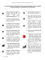
A careful operator is the best protection against accidents. Most accidents
involving operators of equipment are listed below
1)
2)
Only the operator should be allowed on
the machinery when the digger is in
operation.
Make sure they are
instructed and capable of safe
operation.
Carefully
supervise
inexperienced operators. Never allow
children to operate the digger.
Learn how to operate this machine in a
safe, open area before operating in tight
quarters or in conjunction with other
equipment or people.
3)
All bystanders should be kept a
minimum of 10 feet (3 meters) away
from working area of the earth drill.
Never operate the earth drill controls
from the ground. Always operate the
vehicle and earth drill from the correct
operating position.
4)
Always wear an OSHA approved hard
hat and safety eye protection when
operating or servicing this equipment.
Do not wear loose fitting clothing,
flopping cuffs, dangling neckties and
scarves, or rings and wrist watches that
can catch moving parts.
5)
An operator must not use drugs or
alcohol which can change his alertness
or coordination. An operator taking
prescription or over-the-counter drugs
should seek medical advice on whether
or not he can safely operate equipment.
6)
Always locate underground electrical
wires, telephone cables, gas, water
and sewer lines before digging.
Maintain safe clearance and avoid
contact with any underground or
overhead utility lines or electrically
charged conductors.
7)
Never alter or remove any safety decals
or shields.
Replace all missing or
damaged safety decals or safety
shields. Check this manual for location
of these items and replace immediately
if damaged or illegible.
Rev 040610.005
4
8)
Whenever changing or installing this or
other attachments, make sure all
connections are securely fastened.
9)
Avoid steep hillside operation which
could cause the vehicle to overturn.
Consult your vehicle operator’s and
safety manuals for maximum incline
allowable.
10)
Travel only with the earth drill in a safe
transport
position
to
prevent
uncontrolled movement. Drive slowly
over rough ground and on slopes.
Tether earth drill with a chain, if
necessary to prevent uncontrolled
swinging of earth drill when moving from
hole to hole. Remove earth drill from
vehicle when transporting to and from
job site.
11)
Before exiting vehicle, lower earth drill
to ground, turn off vehicle engine and
lock vehicle brakes.
12)
Do
not work on or make any
adjustments to the tractor or digger
while either is in operation. Turn off
tractor engine, lower digger to the
ground and operate digger control
levers to relieve residual hydraulic
pressure before adjustments or
repairs are made, or when leaving the
tractor.
Do not leave the digger
unattended with the auger raised.
Always lower it to the ground.
13)
Never check a pressurized system for
leaks with your bare hand..
Oil
escaping from pinhole leaks under
pressure can penetrate skin and could
cause serious infection. Hold a piece of
cardboard up next to suspected leaks
and wear a face shield or safety eye
protection. If any fluid is injected into
the skin, it must be removed within a
few hours by doctor familiar with this
type of injury.
HYDRAULIC EARTH DRILLS SETUP AND OPERATING MANUAL
corrected
14)
15)
16)
17)
Before disconnecting hydraulic lines or
fittings be sure to relieve all pressure
by cycling all hydraulic controls after
shutdown.
Remember hydraulic
systems are under pressure whenever
the engine is running and may hold
pressure after shutdown.
Before
applying pressure to the system make
sure all connections are tight and that
there is no damage to lines, fittings and
hoses.
Flow and pressure gauges, fittings and
hoses must have a continuous
operating pressure rating of at least
25% higher than highest pressures of
this system.
20)
Check the machine frequently to be
sure there are no loose bolts. Be sure
to immediately tighten any loose nuts
with the proper tools.
21)
Before digging or otherwise operating
the machine, you should carefully
inspect the area to be worked, looking
for and noting all gullies, or ditches, etc.
and removing any posts, trash, wire,
and other obstacles or potential
hazards.
22)
This manual covers the safe use,
installation, operation and service
instructions for the earth drill only.
Always read the operating and safety
manuals prepared for your vehicle and
any other attachments before using
them
23)
Please remember that it is IMPORTANT
that you read and heed the safety signs
(decals) on the digger, and the safety
rules set forth above. Clean or replace
all safety signs (decals) if they cannot
be clearly read. They are for your own
safety as well as the safety of others.
We cannot be there to
make sure that you follow
these rules of safe
operation. The safe use
of this machine is strictly
up to you, the operator.
Never adjust a relief valve for a
pressure higher than recommended by
vehicle manufacturer.
When digging rocky soil, always wear
safety glasses.
18)
Always
19)
Never perform any work on an earth drill
unless you are authorized - and
qualified - to do so. Always read the
operator service manual(s) before any
repair is made.
After completing
maintenance or repair, check for correct
functioning of the earth drill. If not
functioning properly always tag “DO
NOT OPERATE” until all problems are
Rev 040610.005
wear safety glasses and
appropriate protective gear
when working on the digger,
particularly when driving
pins or teeth with a hammer.
5
HYDRAULIC EARTH DRILLS SETUP AND OPERATING MANUAL
HYDRAULIC SYSTEM HOOK-UP INSTRUCTIONS
1)
Once the installation instructions are complete you are now ready to make the hydraulic connections
necessary to operate your earth drill. READ AND UNDERSTAND SAFETY INFORMATION PRIOR TO
MAKING HYDRAULIC CONNECTIONS.
2)
Your equipment dealer is in the best position to advise you the best location on your machine to make
the hydraulic connections to power your earth drill drive unit. The list below shows the most common
places to “tap” into the hydraulic systems on various types on machines.
a. SKID STEER LOADERS
d. TRACTOR 3-POINT HITCHES
i. Auxiliary hydraulic outlets.
i. Remote
(auxiliary)
hydraulic outlets.
b. BACKHOES AND EXCAVATORS **
e. FORKLIFTS
i. Auxiliary hydraulic outlets or
bucket curl cylinder circuit.
c. WHEEL LOADERS AND TRACTOR
LOADERS **
i. Auxiliary hydraulic outlets or
bucket tilt (dump) cylinder
circuit.
i. Auxiliary hydraulic outlets
or side shift circuit
ii.
3)
.
** Note: Some auxiliary outlets on these vehicles are one way circuits only and turn on flow abruptly
with such force that is can cause damage to hydraulic motors and other parts of system and
will not reverse Earth Drill to free the auger if it becomes lodged. Check this before installing
on one of these outlets.
4)
Determine length of hydraulic hoses required to plumb the drive unit into the place on your machine
where you’ll be “tapping” into the hydraulics. Be sure the two hydraulic hoses are long enough to
perform at the full range of the earth drill’s operating capacity.
5)
Fittings on the other end of each hydraulic hose should match the threads on hydraulic quick couplers
to be used.
6)
WARNING! HOSES AND FITTINGS MUST HAVE A CONTINUOUS OPERATING PRESSURE
RATING OF AT LEAST 25% HIGHER THAN HIGHEST PRESSURES OF THE SYSTEM YOU ARE
“TAPPING” INTO.
7)
Once all hydraulic connections have been made and checked for leaks and proper hose lengths, you
are now ready to operate your earth drill.
8)
READ AND UNDERSTAND OPERATING INSTRUCTIONS AND SAFETY INFORMATION PRIOR TO
OPERATING YOUR EARTH DRILL
Rev 040610.005
6
HYDRAULIC EARTH DRILLS SETUP AND OPERATING MANUAL
OPERATING INSTRUCTIONS
1)
After all installation instructions have been
completed, safety information read and
understood and the rest of this operator’s
manual has been reviewed, your Belltec
Hydraulic Drill is now ready for use.
8)
Return the earth drill control valve to the neutral
position to stop the rotation of the auger. Raise
the auger out of the hole, move away from the
hole, then activate the earth drill control valve to
spin the loose soil off of the auger.
2)
With the auger raised off the ground and the
vehicle engine set at a low RPM, activate the
earth drill control valve to determine position
control valve lever must be in to turn auger in
a forward (clockwise) rotation. This is the
“digging” position.
9)
NOTE: Do not reverse the auger rotation to
remove from the hole as loose soil on the auger
flights will fall back into the hole.
10)
If necessary, repeat steps 7 & 8 to obtain a
cleaner hole.
3)
Before beginning to dig, experiment with
auger speed to determine a suitable auger
RPM. Generally in light and sandy soils a
high RPM is desirable. In hard, rocky or
frozen soils a slower RPM is desirable. To
increase auger RPM, increase vehicle engine
RPM. To decrease auger RPM, decrease
vehicle engine RPM.
11)
In some soil conditions or when excessive down
pressure is applied, auger may “screw” itself into
the ground and become stuck causing earth drill
to stall. If this happens, reverse the auger
rotation (counter-clockwise) by moving the
control valve lever to the reverse position and
slowly raise the auger. Once unstuck, return the
control valve lever to the forward rotation position
and continue digging.
4)
Return earth drill control valve to neutral
position to stop the auger. Lower the auger
to the ground so that only the center point
penetrates the ground about 2” (51mm).
12)
If the auger becomes lodged under rocks, roots
or other large obstructions, do not attempt to
raise the auger out of the ground. See step 11
for proper procedure to relieve the auger.
13)
If the auger hits a large obstruction the vehicle
hydraulic relief valve will open and bypass the oil
to stall (stop) the auger. This does not damage
the unit in anyway but serves as a protection
device. Whenever this happens simply reverse
the auger rotation and raise the auger. Once
unstuck you can continue digging.
14)
Avoid excessive side loading to earth drill which
can cause drive unit or auger damage.
15)
Keep auger teeth and points in good condition.
Check frequently and always keep spares on
hand so they can be replaced as wear is
detected to avoid damage to tooth holders and
auger flighting.
5)
6)
7)
Activate the earth drill control valve so auger
is turning in a forward (clockwise) rotation.
Use only enough down pressure to assure
positive penetration of auger into the ground.
Ease up on down pressure if auger rotation
slows down drastically or stalls. Excessive
down pressure will cause the auger to stall
frequently.
When the auger has penetrated the ground
about 24” (610mm), raise the auger from the
hole to clean the dirt out. Repeat this
procedure until the desired hole depth is
obtained.
Once required hole depth is reached, allow
the auger to turn a few seconds at this depth
to clean the hole.
Rev 040610.005
7
HYDRAULIC EARTH DRILLS SETUP AND OPERATING MANUAL
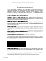
MAINTENANCE INSTRUCTIONS
CLEAN HYDRAULIC OIL IS ESSENTIAL! 80% of all hydraulic component failures are caused by
contamination of the hydraulic oil. Always keep all dirt and other contaminates from entering hydraulic
system during disconnect and connect operations. Always use dust caps and plugs on all quick
disconnects when not in use. Tightly cap all hydraulic openings to hold oil in and keep dirt and other
contaminates from entering hydraulic system.
CHECK HYDRAULIC OIL DAILY FOR CONTAMINATION. If contamination is present, determine the
source of the contamination and correct the problem.
INSPECT ALL HYDRAULIC HOSE ASSEMBLIES DAILY. Replacement of hoses before failure will
prevent loss of hydraulic oil, time consuming “bleeding” of the system, hydraulic oil cavitation. It will also
reduce the chance of personal injury caused by hydraulic fluid.
INSPECT ALL HYDRAULIC HOSE ASSEMBLIES DAILY for cracked and brittle covers caused by
excessive heat. Reduced viscosity of hydraulic oil occurs at higher operating temperatures and causes a
breakdown of fluid additives such as wear inhibitors. Excessive heat will cause higher internal leakage in
drive unit motor, which will make the drive unit less efficient. It can also cause seals in the drive unit
motor to become brittle and crack.
CHECK AUGER DAILY for loose, worn or broken cutting teeth and points. Worn teeth or points can
drastically affect auger penetration and greatly reduce auger life expectancy. Always keep spare teeth
and points on hand. Some digging conditions may require checking teeth and points at more frequent
intervals.
CHECK DRIVE UNIT AND ALL ACCESSORIES DAILY for loose, bent, cracked or worn bolts and
fasteners. Always use grade 5 or harder replacement bolts. Always use lock washers with standard hex
nuts or self-locking nuts.
CHECK DRIVE UNIT OUTPUT SHAFT DAILY for bends, cracks, breaks or wear.
The Planetary reduction gearbox has been filled with lubricant at the factory. If leakage of oil is observed
the seal should be examined for damage or wear, and replaced if necessary. Inspect gearbox for any
other damage, which could be causing leakage of oil, and if necessary repair and refill with lubricant.
When reassembled, fill API-GL-5 No. 80 or 90.
Model
NC150, NC200, NC300
M200, M300, M350
H200, H300, H350
HD400, HD500
Amount of oil needed
13.5 ounces
27.0 ounces
27.0 ounces
84.5 ounces
WHEN STORING DRIVE UNIT for any length of time be sure drive unit motor and hoses are full of clean
oil. Be sure planetary gear reduction is full (to the recommended capacity for each model as outlined in
#9) of clean lubricant.
Drive unit output shaft, inside of auger collar, variable auger extension collar and all connecting pins
should be coated liberally with grease to prevent rust and reduce wear.
Once paint has been worn off of auger, coat liberally with grease, as required, to prevent rusting.
Rev 040610.005
8
HYDRAULIC EARTH DRILLS SETUP AND OPERATING MANUAL
TROUBLESHOOTING CHECK LIST
Any hydraulic tool will perform only as well as the hydraulic system supplying it. Earth Drill Drive Unit
speed (RPM) is dependent upon the system pump output in gallons (liters) torque (power) is dependent
upon the relief valve pressure setting-PSI (kg/cm2).
If your Belltec Hydraulic Earth Drill does not appear to have enough speed or power, use the following
checklist to solve the problem.
SLOW SPEED (rpm) OR INSUFFICIENT DIGGING POWER.
Check pressure relief valve setting (PSI) or (kg/cm2) and hydraulic pump output (GPM) (lpm) by installing
a combination flow and pressure gauge in the line supplying the drive with oil. Gauge must be installed
beyond all valves and quick disconnects in order to get a true reading at the drive unit. It is imperative
that the flow meter gauge be monitored closely as the digging operation progresses. The hydraulic
system flow (GPM) (lpm) should remain the same and not drop off until the stall pressure (PSI) (kg/cm2) is
achieved. If readings are not up to the vehicle manufacturers specifications, check for faulty relief valve
and adjust or replace as required. A worn, damaged or insufficient hydraulic pump may also be a possible
cause.
Are there any hydraulic line restrictions? Smaller than recommended valve and hose sizes, dirty or
clogged filters, and dirty or faulty quick disconnects are examples of line restrictions that will affect drive
unit performance.
Check auger and teeth for excessive wear. A worn or tapered auger or worn cutting teeth and points will
drastically reduce the augers ability to penetrate the ground.
EXCESSIVE OIL HEATING
Line restrictions (see #1B), insufficient reservoir size to pump output ratio, oil passing over relief valve
frequently, low oil level in reservoir, and dirty oil are all conditions which will cause oil to overheat. If oil is
heating excessively, check for these conditions and remedy the situation. Excessively hot oil will greatly
reduce the drive unit performance, as well as damage seals, hoses and other hydraulic system
components.
OIL LEAKS
Check hydraulic motor seals and replace as necessary.
Check planetary gear reduction seals and gaskets and replace as necessary.
Check all hoses and fittings and tighten or replace as necessary.
If the above trouble-shooting checklist does not resolve your problem please contact our service
department as follows:
Rev 040610.005
9
HYDRAULIC EARTH DRILLS SETUP AND OPERATING MANUAL
[THIS PAGE INTENTIONALLY BLANK]
Rev 040610.005
10
HYDRAULIC EARTH DRILLS PARTS BOOK
PARTS BOOK
FOR
HYDRAULIC EARTH DRILLS
Models
NC150, NC200, NC300
M200, M300, M350
H200, H300, H350
HD400, HD500
Rev 040610.005
11
HYDRAULIC EARTH DRILLS PARTS BOOK
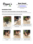
DECALS
!
DA N G E R
Rotating Parts Hazard
Keep Away
To Prevent Serious Injury
or Death from Rotating Parts:
Read and understand owner's manual before operating.
Do not operate without all shields and guards in place.
Do not use body weight to force the auger into the
ground or to locate auger point when auger is turning.
Keep away from auger, cutting head and driveline when
engine is running.
The above safety sign is located near the bottom of the hydraulic drive housing. If damaged or missing
order a new “DANGER” decal. We will gladly send a new one at no charge.
! DA N G E R
TO PREVENT SERIOUS INJURY OR DEATH
Contact dealer, make sure your machine has all
current safety guards and shields in place.
Do not operate without all guards and shields in
place
Do not operate when auger is higher than 12
inches above ground level.
Stop auger rotation before maneuvering,
relocation or transporting.
Rev 040610.005
12
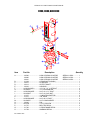
HYDRAULIC EARTH DRILLS PARTS BOOK
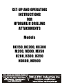
H200, H300, AND H350
Q
O
N
P
S
E
A
R
F
G
B
K
J
C
M
I
L
H
Item
Part No
D
Description
Quantity
A ................... 112500.......................... H200 HYDRAULIC MOTOR
SERIAL # 4700.............. 1
112600
H300 HYDRAULIC MOTOR
SERIAL # 4700.............. 1
112601
H350 HYDRAULIC MOTOR
SERIAL # 4550.............. 1
B ................... 111324.......................... O-RING (NOT SHOWN)......................................................... 1
C ................... 112475.......................... PLANETARY .......................................................................... 1
D ................... 113312.......................... OUTPUT SHAFT .................................................................... 1
E ................... 113222.......................... HOUSING............................................................................... 1
F ................... HCS050150Z12............ 1/2”-13X 1 ½” 12 PT BOLT .................................................... 4
G................... HLW050Z...................... 1/2” LOCKWASHER............................................................... 4
H ................... HCS05622255Z............ 9/16”-12 X 2 ¼” BOLT ............................................................ 5
I..................... HLN0562T .................... 9/16”-12 LOCK NUT............................................................... 5
J.................... 111337.......................... 10 MB 8FPX ADAPTOR......................................................... 2
K ................... 111315.......................... 108” HOSE ............................................................................. 2
L.................... HCS05622005Z ........... 9/16”-18 X 2” BOLT ................................................................ 6
M................... HLW056Z...................... 9/16” LOCKWASHER............................................................. 6
N ................... 113206.......................... PIN.......................................................................................... 1
O................... HLP044......................... 7/16” LYNCH PIN ................................................................... 2
P ................... 111757.......................... BELLTEC DECAL .................................................................. 2
Q................... 111766.......................... H-DRIVE NAME DECAL ........................................................ 1
S ................... 111758.......................... WARNING DECAL ................................................................. 2
Rev 040610.005
13