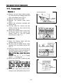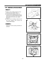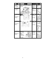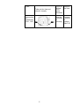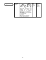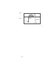
1
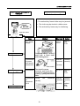
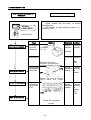
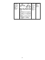
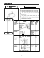
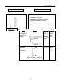
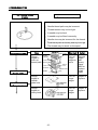
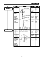
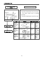
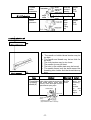
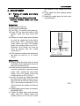
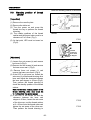
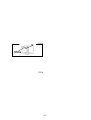
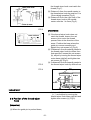
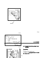
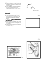
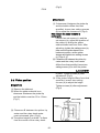
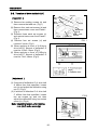
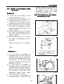
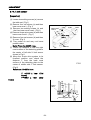
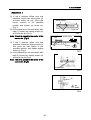
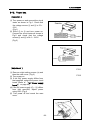
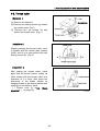
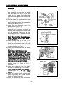
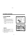
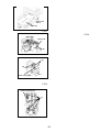
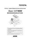
SERVICE MANUAL
Embroidery Machine
ESP9000
(15
needles)
How to Use this Service Manu
al
1.This service manual applies to the ESP9000.
Model names are indicated only for sections equipped with each model.
2.Refer to the section on TROUBLESHOOTING first.
Trouble often results from two or more causes. The TROUBLESHOOTING
section indicates the correct order and method of troubleshooting. When
need arises to repair the embroidery machine in reference to this Service
Manual, refer to TROUBLESHOOTING first. Then, refer to ADJUSTMENT or
REPLACEMENT as suggested.
3.Only the critical instructions are given.
When a component must be removed for troubleshooting, adjustment or
replacement, the Service manual explains how to remove other components
before the component in question can be removed.
However, the manual does not explain how the other components are fitted,
unless such information is necessary for technical reasons, when adjustment
or replacement is completed.
Inspection & Repairs
1.When parts need to be replaced, use only parts certified by Aishin Seiki Co.,
Ltd., to ensure machine performance.
2.To prevent any accident from occurring, be sure to turn the power OFF
before repair.
CONTENTS
1
.
SPECIFICATIONS...............................................................................................................
.....................1
2
.
TROUBLESHOOTING............................................................................................
.......................2
2-1
The
power
supply
does
not
turn
!
SEWING
on........................................................................................2
2-2
An
error
message
is
displayed
”Check
MOTOR”........................................3
2-3
An
error
message
is
displayed
“Check
!
X
MOTOR”......................................................4
2-4
An
error
message
is
displayed
Check
”
!
Y
MOTOR”.....................................................5
2-5
An
error
message
is
displayed
”NEEDLE
CASE
ERROR” ............................................6
2-6
Holder
does
not
return
to
stroke
center
after
home
position
return......................7
2-7
Thread
comes
off
needle.............................................................................................................8
2-8
Skips
stitches..................................................................................................................................
..9
2-9
Needle thread
breaks...................................................................................................................10
2-10
Bobbin
thread
breaks...................................................................................................................12
2-11
Needle
breaks..................................................................................................................................1
3
2-12
Thread
wiper
hook
does
not
operate....................................................................................14
2-13
Thread
trimming
fails....................................................................................................................15
2-14
Puckering...............................................................................................................................
............16
2-15
Improper
tension............................................................................................................................17
2-16
Jump
function
does
not
work...................................................................................................18
2-17
An
error
message
is
displayed
“THREAD
BREAK” .......................................................19
2-18
Stitch
registration
out.......................................................................................................20
slips
3.ADJUSTMENT OF MAIN COMPONEN
TS..................................21
3-1
Timing
of
the
needle
and
the
rotary
hook...........................................................................21
3-2
Position
of
the
hook
support....................................................................................................23
3-3
Standby
position
of
thread
catcher.......................................................................................24
3-4
Blade
pressure................................................................................................................................
25
3-5
Picker
position................................................................................................................................2
7
3-6
Position
of
the
thread
wiper
jump
motor
hook..........................................................................................28
3-7
Adjustment
of
the
position...............................................................................29
3-8
Tension
of
drive
belts
A
&
C....................................................................................................30
3-9
Tension
of
deceleration
belts
B,
D,
E...................................................................................31
3-10
Limit
sensor....................................................................................................................................
..32
3-11
Thread
sensor.................................................................................................................................3
4
3-12
Power
box.........................................................................................................................................
35
4.REPLACEMENT
OF
MAIN
COMPON
ENTS..........................36
4-1
Rotary
hook.......................................................................................................................................
36
4-2
Thread
cutter...................................................................................................................................3
7
4-3
Thread
catcher................................................................................................................................3
8
4-4
Needle
bar.........................................................................................................................................
.39
4-5
Needle
bar
reciprocator...............................................................................................................41
4-6
Thread
change
motor...................................................................................................................43
4-7
Power
supply
board.......................................................................................................................44
4-8
Power
circuit
board........................................................................................................................45
4-9
Jump
motor.....................................................................................................................................
..46
4-10
Main
circuit
board...........................................................................................................................47
4-11
Operation
box
assembly...............................................................................................................48
4-12
Upper
shaft
sensor.........................................................................................................................49
4-13
Sewing
machine
motor..................................................................................................................50
4-14
X
motor.....................................................................................................................................
...........51
4-15
Y
motor.....................................................................................................................................
...........52
4-16
Thread
wiper
motor........................................................................................................................53
4-17
Thread
sensor...................................................................................................................................
54
4-18
Operation
control
board................................................................................................55
circuit
4. REPLACEMTNT OF MAIN COMPONENTS
4-9. Jump motor
[Removal]
(1) Remove the needle case.
[Please refer to 『“ 4-5. Needle bar
reciprocator” 』 on page 41]
(2) Remove five set screws (a) and the arm
front cover L. (Fig.1)
(3) Remove each setting screws and the
thread stand plate, bobbin winder base
and rear cover. (Fig.2)
(4) Cut the cable tie and remove the relay
harness.
(5) Remove two setting screws (b) and the
jump motor set. (Fig.3)
(6) Loosen the setting screws (c) and
remove the jump lever holder. (Fig.4)
(7) Remove four setting screws (d) and the
jump motor. (Fig.4)
(a)
Arm front cover L
FIG.1
Thread stand plate
Rear cover
[Installation]
Bobbin winder base
FIG.2
(1) Install the jump motor with four setting
screws (d). (Fig.4)
(2) Hang the jump lever return spring on
the jump lever holder and pull down the
spring as low as possible so that the
spring will not be located on the jump
positioning collar. (Fig.4)
(3) Tighten the setting screw (c) and check
that the jump lever holder returns with
the spring and stops with the stopper.
(Fig.4)
(4) Install the jump motor set with two
setting screws (b). Adjust the clearance
between the jump lever and the needle
reciprocator at 0.5 mm by moving the
jump motor right and left.
(5) Connect the relay harness, bundle the
cord with cable tie and install the thread
stand plate, bobbin winder base and
rear cover.
(6) Install the needle case.
(b)
Jump motor set
FIG.3
Jump positioning
collar
Jump lever return spring
Stopper
(d)
(d)
(c)
-46-
Jump lever holder
FIG.4
4.REPLACEMENT OF MAIN COMPONENTS
4-10. Main circuit board
[Removal]
(1) Remove two setting screws (a) and the
table set. (Fig.1)
(2) Remove four set screws (b) and the
base cover rear R. (Fig. 1)
(3) Loosen two setting screws (c), remove
other two set screws (d), move the
case cover upper upwards, disconnect
the connector CN2 and remove the
case cover upper. (Fig.2)
(4) Disconnect all the connectors. (Fig.3)
(5) Remove two setting screws (e) and
remove the main circuit board by
holding the plastic spacer with pliers.
(b)
Base cover
rear R
(a)
Table set
FIG.1
[Installation]
(d)
Attached in the reverse procedure of
removal
(c)
Case cover
upper
Main circuit board
FIG.2
(e)
CN2
-47-
FIG.3
-48-
4.REPLACEMENT OF MAIN COMPONENTS
4-11. Operation box assembly
[Removal]
(1) Loosen retaining screw (a) and rotate
the operation box in the direction of the
arrow to set the box in the upright
position (Fig.1).
(2) Remove retaining screw (b) and two
retaining screws (c) and the operation
box cover (Fig.1).
(3) Remove four retaining screws (d).
Unplug the cord and remove the
operation box (Fig.2).
FIG.1
[Installation]
(1) Plug in the cord.
(2) Secure the operation box to the
bracket with four retaining screws (d).
One of these screws is for grounding
(Fig.2).
(3) Mount the operation box cover with
retaining screw (b) and two retaining
screws (c) (Fig.1).
(4) Rotate the operation box to set it at
the desired angle for easy operation
and secure it with retaining screw (a)
(Fig.1).
FIG.2
-49-
[Installation]
(1) Install the upper shaft sensor on the
sensor base with two setting screws (d).
(Fig.3)
(2) Insert the connector of the upper shaft
sensor in CN3 on the main circuit board.
(Fig.5)
(3) Fix the upper shaft sensor set with two
setting screws (c) in the position where
the center of the sensor comes to the
center of the rotation detecting plate.
(Figs.2, 4)
(4) Bundle the cords with cable tie.
(5) Set the DS1-1 on and turn the power
on. Rotate the hand wheel to move the
needle bar to the bottom dead center.
Check that the LCD display shows the
needle position at 180°.
Note: In case the LCD display does not
show 180 ° , loosen the set screw,
adjust the position of the detecting
plate and fix it. (Fig.1)
(6) Install the case cover upper, base
4.REPLACEMENT OF MAIN COMPONENTS
cover rear L, rear cover and bobbin
winder base set.
4-12. Upper shaft sensor
[Removal]
(a)
(1) Remove two setting screws (a) and the
bobbin winder base set. (Fig.1)
(2) Loosen four setting screws (b) and
remove the rear cover. (Fig.1)
(3) Remove two setting screws (c) and the
upper shaft sensor set. Then remove
two setting screws (d) and the upper
shaft sensor. (Figs.1, 2)
(4) Remove four setting screws and the
base cover rear L. (Fig.1)
(5) Loosen two setting screws, remove
other two setting screws, move the
case cover upper upwards, disconnect
the connector CN3 and cut the cable
tie and then remove the upper shaft
sensor. (Refer to Fig.2 on page 47)
Rear cover
(b)
(b)
Bobbin winder base set
Base cover
Rear L
FIG.1
Upper shaft sensor set
(c)
FIG.2
Upper shaft sensor
-50-
[Installation]
(1) Two set surfaces of the sewing
machine motor shaft and two setting
screws (c) of the lower shaft joint are
aligned and insert the sewing machine
motor.
(2) Fix the sewing machine motor with four
setting screws (d). (Fig.4)
(3) Insert two setting screws (c) of the
lower shaft joint gradually, locate them
vertically to the setting points and
tighten them.
(4) Insert two connectors and bundle the
cords with the cable tie.
(5) Install case cover upper with four
setting screws (a) and (b). (Fig.1)
(6) Install the base cover rear R.L. and the
rear cover.
FIG.3
Center
Upper shaft sensor
Detecting plate
FIG.4
Main circuit board
CN3
FIG.5
4.REPLACEMENT OF MAIN COMPONENTS
4-13. Sewing machine motor
[Removal]
(1) Remove the rear cover and base cover
rear R.L.
(2) Loosen two set screws (a), remove
other two set screws (b), move the
case cover upper, disconnect CN5 of
the main circuit board and CN3 of the
power circuit board and cut the cable
tie. (Figs.1, 2)
(3) Loosen two setting screws (c), which
are located on the motor side of the
lower shaft joint. (Fig.1)
(4) Remove four setting screws (d) and the
sewing machine motor. (Fig.4)
(b)
(a)
Case cover
upper
FIG.1
CN5
-51-
Main circuit board
CN3
(4) Remove four setting screws (d) and X
motor from the bracket. (Fig.2)
FIG.2
[Installation]
Power circuit board
Lower shat joint
Sewing machine
motor
(c)
Arm bed
FIG.3
Power circuit board
(1) Mount the X motor to the motor base
with four setting screws (d) (Fig.2).
(2) Set the X motor gear to the belt and
temporarily secure the motor base to
the X base B with two setting screws
(c) (Fig.2).
(3) Adjust the belt tension by setting
screw (b) and firmly tighten two
setting screws (c), then tighten the
nut. (Figs.2, 3)
Note: Check the tension, after tighting
screws (c).
(4) Insert the connector.
(d)
Sewing machine
motor
FIG.4
4.REPLACEMENT OF MAIN COMPONENTS
4-14. X motor
[Removal]
(1) Remove two setting screws (a) and
motor cover. (Fig.1).
(2) Loosen the nut and remove the
setting screw (b). (Fig.2)
(3) Disconnect the connectors. Remove
two setting screws (c) and the X
motor. (Fig.2)
(a)
Motor cover
-52-
FIG.1
(d) X base B
Nut
(b)
X motor
(c)
Motor base
4.REPLACEMENT OF MAIN COMPONENTS
4-15. Y motor
[Removal]
(1) Remove four set screws (a) and the
base cover rear R. (Fig.1)
(2) Remove two setting screws (b) and the
fan set. (Fig.2)
(3) Remove the Y pulley box adjusting
screw (c) and nut (d) and loosen
setting screw (e) and nut (f). (Fig.2)
FIG.2
-53-
(4) Disconnect the connector, remove two
set screws (g) and Y motor bracket set.
(Fig.3)
(5) Remove four setting screws (h) and the
Y motor. (Fig.4)
[Installation]
(1) Mount the Y motor to its bracket with
four setting screws (h). (Fig.4)
(2) Set the Y motor gear to the belt and
temporarily secure them with two
setting screws (g). (Fig.3)
(3) Adjust the belt tension with setting
screw (e), and then firmly tighten with
two setting screws (g) and nut (f).
(Fig.3)
Note: Check the tension, after tighting
screws (g).
(4) Insert the Y pulley box adjusting
screw (c) into the backmost position
and tighten the nut (d). (Fig.3)
(5) Mount the fan set with two setting
screws (b). (Fig. 2)
(6) Insert the connector.
FIG.1
Fan set
(b)
FIG.2
Y motor bracket set
(g)
(d)
(a)
Base cover
rear R
-54-
(c)
(e)
(f)
wiper motor. (Fig.1)
(4) Remove the setting screw (d) and (e),
and the upper thread hook lever.
(Fig.3)
(5) Remove the three setting screws (f)
and the motor base.(Fig.3)
Note: Be sure to insert the small
washer that is contained in each
setting screws of (3) and (4) sections.
FIG.3
(h)
Y motor bracket
[Installation]
(1) Attached in the reverse procedure of
removal
Note: Set the vertical position of the
upper thread hook lever slightly
upward, and make sure that the
connecting rod plate has a little play.
(2) After attaching, check the distance A
from the needle center to the thread
wiper hook tip. [Please refer to 『“ 3-6
Position of the thread wiper hook.” 』
on page 28 ]
(3) If the distance A differs from that
specified, loosen two setting screw (c)
and adjust by moving the thread wiper
motor base up/down.
Y motor
FIG.4
4.REPLACEMENT OF MAIN COMPONENTS
4-16. Thread wiper motor
[Removal]
(1) Remove the each setting screws (a)
and the change cover, the relay circuit
board cover, the thread stand plate,
the bobbin base and the rear cover.
(Fig.1)
(2) Cut a cable tie and remove the relay
connector.
(3) Remove the setting screw (b) and two
setting screws (c), and the thread
Change cover
(a)
Relay circuit
board cover
(a)
(a)
(a)
-55-
Thread stand
plate
Bobbin winder
base
Rear cover
FIG.2
Motor base
Upper thread
hook lever
(f)
(e)
(d)
FIG.1
Thread wiper
motor base
(c)
FIG.3
(b)
Connecting
rod plate
Thread wiper
hook base
-56-
4.REPLACEMENT OF MAIN COMPONENTS
4-17. Thread sensor
[Removal]
Tension base cover
(1) Remove the two each setting screws
(a), then remove the change cover and
relay circuit board cover. (Fig.1)
(2) Remove the connector CN2.
(3) Remove the tension base cover.
(Fig.1)
(4) Raised the connector upwards and
disconnect it.
(5) Cut the cable tie, remove the two
setting screws (b) then remove the
sensor arm. (Fig.4)
(6) Extract the thread sensor base from
the thread sensor rail; remove the
setting screw (c) and the thread
sensor board. (Figs.3, 4)
(a)
Change
cover
Relay circuit board cover
FIG.1
[Installation]
Sensor arm
(b)
FIG.2
(1) Attach the sensor board with the
setting screw (c). (Fig. 4)
(2) Put the code of thread sensor base
upwards into the thread sensor rail.
(Fig. 3)
(3) Putting a sensor arm into the slot of
the thread sensor base and secure it
with two setting screws (b). (Fig.2)
Note: At this time, check the sensor
position.
[Please refer to 『 “ 3-11. Thread
sensor” 』 on page 34]
(4) Secure the cord with a cable tie and
insert the connector.
Note: The blue field of a code is
turned and inserted in a spool side. At
this time, check the connector
connection by pulling a code with
hand.
(5) Mount the relay circuit board cover,
change cover and tension base cover.
Thread sensor rail
Thread sensor base
FIG.3
(c)
Sensor board
FIG.4
-57-
4.REPLACEMENT OF MAIN COMPONENTS
4-18. Operation control circuit board
[Removal]
(1) Remove four setting screws (a) and
the base cover rear R. (Fig.1)
(2) Loosen the two setting screws (b),
remove the two setting screws (c) and
disconnect connectors CN12 and CN7,
then remove the case cover upper.
(Fig.2,3)
(3) Remove the two setting screws (d) and
the resin spacers, then remove the
console board (Fig.4).
(a)
Base cover
rear R
FIG.1
(c)
[Installation]
Attached in the reverse procedure of
removal.
(b)
Case cover
upper
FIG.2
CN12
CN7
FIG.3
Console board
(d)
-58-
FIG.4
-59-
1.SPECIFICATIONS
1.SPECIFICATIONS
ESP9000
No
1
Item
Specifications
Lock stitch type sewing machine (for automatic embroidery
Type of stitch
only)
2
Rotary hook
Vertical 2 revolution type (eccentric)
3
Thread take-up lever
Cam take-up lever
4
Needle bar stroke
50 ± 0.2 mm
5
Number of needles
15 (auto changing)
6
Applicable needles
Organ DB×K5Z #11
7
Presser foot
Needle bar linked driving system (with noise
reduction mechanism)
8
Bobbin thread winding
Semi-auto winding (auto return, also stop)
9
Thread trimming method
Horizontal reciprocation (motor drive)
10
Thread wiper
Motor
drive
sliding
type
(with
thread
retaining
mechanism)
11
Picker method
Picking at start, end of sewing and cutting thread
12
Stitch speed
1,200spm maximum (800spm standard)
13
Embroidery area
360 mm long × 500 mm wide
14
Embroidery
control
and Touch switch control with LED/LED displays
indication
15
Stitch memory
280,000 stitches
16
Memory back-up
Memory saved during operation and after power off;
kept for 4 weeks
17
Weight
80 ± 1kg (without table)
18
Machine oil
High grease NX 2, molybdenum grease NO 2, SF oil
(multi-grade)
19
Drive motor
AC servo motor (machine revolution)
20
Control motor
AC servo motor (X axis, Y axis)
21
Needle thread failure detection
Rotary detection system (photo sensor)
-1-
22
Power supply and consumption
100~120/200~240VAC, 50/60Hz, 220W
23
Dimensions
835(H) x 745(W) x 740(D)
-2-
2.TROUBLESHOOTING
2.TROUBLESHOOTING
2-1 The power supply does not
turn on
Preliminary inspection
・ Power cord may be unplugged (AC power
cord).
・ Cable from the power box to the embroidery
machine may be disconnected (DC power
cord).
Power box
Main circuit board
Console 1 board
Console 2 board
-2-
Item
Method
Standard
Action
Fuse
(outside)
Take out fuse and inspect it 250V6.3
visually
A,without
fusion
Replace
fuse.
5V power
supply
5.0to5.2V Adjust or
when
replace
turned on the
power
Check the voltage across ①
box. See
and ⑦with a circuit tester.
P.44.
Connection
of
connector
CN 12
CN12
Connection
of
connector
CN 7
Connection
of
connector
CN 3
CN7
Remove
the cover
and
inspect
connectio
n
visually
-3-
Must be
connecte
d
correctly
Connect
the cable
correctly or
replace the
main circuit
board See
P.47.
Must be
connecte
d
correctly
Connect
the cable
correctly
or
replace
the main
circuit
board.
See
P.55.
Must be
connecte
d
correctly
Connect
correctly
or
replace
defective
connectors.
See P48.
2.TROUBLESHOOTING
2-2 An error message is
displayed
Preliminary inspection
・ Upper shaft torque may be too large
・ Needle may be interfering with the embroidery
“Check! SEWING
MOTOR ”
hoop.
・ Thread may be stuck.
Operation panel
Power box
Item
Method
Standard
24V power
supply
24.0 to
24.5V
Replace
See
P.44.
Must be
connecte
d
correctly
Connect
correctly
Check the voltage across⑤
and ⑪ with a circuit tester
while shorting⑧to⑨.
Sewing motor
Connector
connection
Resistance
Power circuit board
Check connector visually.
Disconnect the power
connector, and check the
resistance between ①and②,①
and③,②and③ with a circuit
tester.
Connection
CN3
of
connector
Main circuit board
Action
0.2 to 0.6 Replace.
Ω
See
P.50.
Must be
connecte
d
correctly
CN 3
Check
visually.
-4-
the
connector
Connect
correctly
or
replace
See
P.45.
Connection CN3
of
connector
Must be
connecte
d
correctly
CN 3
-5-
Connect
the cable
correctly
or replace
the main
the circuit
board.
See P.47.
2.TROUBLESHOOTING
2-3 An error message is
displayed
Preliminary inspection
・The embroidery frame holder may be jammed.
・ The cloth may be stuck at a table corner.
“Check!
X MOTOR ”
・ The embroidery frame may be interfering.
.
Operation panel
Power box
Item
Method
Standard
24V power
supply
Check the voltage across ⑤
and⑪with a circuit tester, while
shorting⑧to⑨.
X motor
Power circuit board
24.0 to
24.5V
Action
Replace
See
P.44.
Connection
of power
and sensor
connectors
Must be
connecte
d
correctly
Connect
correctly
Resistance
Disconnect
the
power 0.4 to 0.8
connector, and check the Ω
resistance between①and②,
① and ③ , ② and ③ with a
circuit tester.
Replace.
See
P.51.
Connection Check
of
visually.
connectors
CN 1, CN 4 CN1
Main circuit board
-6-
the
connector Must be
connecte
d
CN4 correctly
Connect
correctly
or
replace.
See
P.45.
Fuse
Take out the fuse and
check it visually.
Connection
of
connectors
CN 1, CN7 CN1
CN7
-7-
125V,20
A Must
be in
good
condition
.
Replace
the fuse.
Must be
connecte
d
correctly.
Connect
correctly
or
replace.
See P.47.
2.TROUBLESHOOTING
2-4 An error message is
displayed
Preliminary inspection
・The embroidery frame holder may be jammed.
“Check!
Y MOTOR ”
・ The cloth may be stuck at a table corner.
・ The embroidery frame may be interfering.
Operation panel
Power box
Item
Method
Standard
24V power
supply
24.0 to
24.5V
Action
Replace
See
P.44.
Check the voltage across⑤
and ⑪ with a circuit tester,
while shorting⑧to⑨.
Y motor
Connection
of power
and sensor
connectors
Resistance
Power circuit board
Must be
connecte
d
correctly
Connect
correctly
Disconnect the power
0.2 to 0.5 Replace.
connector, and check the
Ω
See
resistance between①and②,
P.52.
①and ③, ②and③with a circuit
tester.
Connection Check
of
visually.
connector
the
CN 2
CN2
Main circuit board
-8-
connector Must be
connecte
d
correctly
Connect
correctly
or
replace.
See
P.45.
Fuse
Take out the fuse and
check it visually.
Connection
of
connectors CN4
CN 4, CN
6.
CN6
-9-
125V,20
A Must
be in
good
condition
.
Must be
connecte
d
correctly.
Replace
the fuse.
Connect
correctly
or
replace.
See P.47.
2.TROUBLESHOOTING
2-5 An error message is
displayed
“NEEDLE
CASE ERROR ”
Preliminary inspection
・ Upper thread may be stuck, or thread
trimming error.
・ LCD display at right bottom corner is <->
instead of <8>.
Operation panel
Item
Thread change
motor (pulse motor)
Connection
of power
connector
Method
Connector
①-⑥
Resistance
Joint circuit board
Power circuit board
Connection
of connectors
CN 3, CN 4
Disconnect the power
connector and check the
resistance between ① and ⑤
Standard
Action
Must be
connecte
d
correctly.
Connect
correctly
4.8 to 6.0 Replace
Ω
.
See
P.43.
Must be
CN3 connected
correctly.
CN4
Connect
correctly
or
replace.
Remove the cover of the joint
circuit board and check
visually
Connection
of connector
CN 7.
Must be
Connect
connected correctly
correctly.
or
replace.
See
P.45.
CN7
Main circuit board
Check the connector
visually.
-10-
Connection
of connector CN10
CN 10.
-11-
Must be
Replace.
connected See
correctly.
P.47.
2.TROUBLESHOOTING
2-6 Holder does not return
to stroke center after
home position return.
Preliminary inspection
・ Initialize of LCD display may be OFF when
turn the power on.
Operation panel
Item
X Y holder
X.Y holder
position
check
Method
Standard
Photo-sensor
X holder
X=65.7
±1mm
Y=213.5
±1mm
Action
Adjust
See
P.32.
(Position
of
cap
frame
sensor is
Y=133.5
The distances X,, set the joint plate at the
±1mm)
original position (X0, Y0) and check the
distances from the surface of the detecting C=1±
plate to the center of the photo-sensor.
0.5mm
The distances Y, set the X holder to its
forefront position by pressing the emergency
stop button, and check the distances from
the surface of the detecting plate to the center
of the photo-sensor.
Slit
Joint plate
Limit sensor
Connection
of sensor
connector
Output
voltage
X Y motor
Must be Connect
connecte correctly.
d
correctly.
When
Replace.
obstructed:
Turn the power on and check 3.5~5V
voltage across ⑤(green)and ⑥ When not
(blue) with a circuit tester.
obstructed:
0~0.8V
-12-
Phase U,
phase V,
phase W,
phase A
and
phase B
output
Press the emergency stop
button. While turning the motor
by hand, check the voltage of the
sections below with a circuit
tester.
(X motor)
Across ⑫ GND (red and black)and:
① +U (yellow) ② -U (yellow and
black)
③ +V(white) ④ -V(white and black)
⑤ +W(brown)
⑥ -W(brownand
black)
⑦ +A(orange) ⑧ -A(orange and
black)
⑨ +B(pink) ⑩ -B(pink and black)
(y motor)
Across ⑦GND (red and black) and:
① U(yellow) ② V(white)
③ W(brown) ④ A(orange)
⑤ B(pink)
-13-
X motor :
in the
range of 0
to 3.5 V
Y motor :
in the
range of 0
~5V
Replace.
See
Pgs.51
and 52.
2.TROUBLESHOOTING
2-7 Thread comes off
needle.
Preliminary inspection
・ The needle thread tension may be too high.
・ The bobbin thread tension may be too high.
・ The thread may be stuck on the thread
take-up lever.
・ The margin of the needle thread may be
insufficient. (The setting value of (9) of a
Thread wiper
mechanism
function key is enlarged)
Item
Thread
wiper hook
return
Method
Push the guide pin
down as far as it
will go in the
direction of the
arrow and
check the
Guide pin
returning
movement of
the pin.
Hook tip
damage
Picker
Upper thread hook
Clearance
between
the picker
and the
bobbin
Standard
Must
return
smoothly
.
B=1mm
or less
Clearance between the picker tip
center and rotary hook center
-14-
Adjust.
See
P.28.
No
Repair.
damage is
identified
on the
hook tip.
Press the picker gently until it
stops. Check the clearance A=0.5~
between the picker tip and the 1.5mm
bobbin.
Picker
right/left
position
Action
Adjust.
See
P.27.
Adjust.
See
P.27.
Picker
height
C=7~9
mm
(when
piker
solenoid
is ON)
-15-
Adjust.
See
P.27.
2.TROUBLESHOOTING
2 8 Skips stitches
Preliminary inspection
・ A needle may be bent.
・ A needle may be fitted incorrectly.
・ Thread path may be incorrect.
・ Cloth tension may be too weak.
・ Needle size may be incorrect for the thread.
Needles and
rotary hook
Item
Method
Standard
Action
Needle and
rotary hook
timing
A=201°± Adjust.
3°
See
(Standar P.21.
d 1.8 to
3.1mm)
Needle to
hook
clearance
B=0.1to
0.3mm
Align the needle to the
hook tip, and check the
clearance B visually.
-16-
Adjust.
See
P.21.
2.TROUBLESHOOTING
2-9 Needle thread
breaks
Preliminary inspection
・ Needle thread path may be incorrect.
・ Thread tension may be too tight.
・ A needle may be bent.
・ A needle may be fitted incorrectly.
・ Needle size may be incorrect for the thread.
・ Thread density set to embroidery data may be to high.
・ The thread may be stuck on the spool.
Needle thread path
Item
Standard
Action
Free of
rough
edges or
burrs
Smooth
edges
with
emery
paper
#800 or
replace
tough
parts.
Rouge
edges in
needle
plate hole
Free of
rouge
edges
Repair or
replace.
Rouge
edges on
rotary hook
Free of
rouge
edges
Repair or
replace.
Rouge
edges or
burrs on
thread path
Method
First Tension
Rotary
Tension
Thread Take-up
Attaching Base
Lower Thread
Guide Set
Take-up
Lever
Needle Clamp
Needle
Needle plate
Rotary hook
-10-
2.TROUBLESHOOTING
Needles and
rotary hook
Item
Method
Needle lift
Hook tip placed
at needle center
Needle bar
height
Lowest needle
position
Needle
height
(reference
value)
Rotary hook
center
Needle to
hook
clearance
Needle
Rotary hook
tip
Standard
Action
A=201°± Adjust.
3°
See
(Standar P.21.
d 1.8 to
3.1mm)
B=8.0±
0.1mm
Adjust.
See
P.21.
C=1.0±
0.5mm
Adjust.
See
P.21.
D=0.1 to
0.3mm
Adjust.
See
P.21.
Align the needle to the
hook tip, and check the
clearance B visually.
Hook support
Check the protrusion on Free of
Rouge
rouge
hook support visually.
edges on
edges
hook
support
Clearance
A=0.5 to
under the
0.8mm
rotary hook
support
Relative
B=
positions of Center of
Center ±
the center
Protrusion
0.2mm
on Hook
of the
support
protrusion
on the hook
support
and the
center of
the needle
-11-
Repair or
replace.
See
P.23.
Adjust.
See
P.23.
Adjust.
See
P.23.
2.TROUBLESHOOTING
2-10 Bobbin thread
breaks
Preliminary inspection
・ The bobbin thread tension may be too tight.
・
The bobbin thread may be threaded
incorrectly.
・ The bobbin thread may be wound too loose.
Needle plate
Item
Method
Standard
Action
Free of
burrs
Rotary hook
Burred
edges on
hold in the
needle
plate
Repair or
replace
the
needle
plate.
Free of
burrs
Bobbin case
Burred
edges on
the rotary
hook
Repair or
replace
the rotary
hook.
See P.36.
Burred
edges on
the bobbin
case
Free of
burrs
Repair or
replace
the
bobbin
case.
-12-
2.TROUBLESHOOTING
2-11 Needle breaks
Preliminary inspection
・ The needle may be clamped incorrectly.
・ The needle may be bent or blunt.
・ The needle may be too thin for the cloth.
・ The starting position may be incorrect.
Needle and rotary
hook
Thread wiper
mechanism
Item
Method
Standard
Action
Needle to
rotary hook
clearance
A=0.1 to
0.3mm
Adjust.
See
P.21.
Needle bat
height
B=201°±
3°
(Standar
d 1.8 to
3.1mm)
Adjust.
See
P.21.
Needle lift:
D
C=8.0 ±
0.1mm
Adjust.
See
P.21.
Needle lift:
(Reference
value: C)
D=1.0 ±
0.5mm
-13-
Must
return
smoothly
.
Thread
wiper hook
return
Guid
Push the guide pin down as
far as it will go in the direction
of the arrow and check the
returning movement of the
pin.
-14-
Adjustme
nt is
performe
d by
loosenin
g a guide
pin
screw.
2.TROUBLESHOOTING
2-12 Thread wiper hook
does not operate
Preliminary inspection
・ Thread wiper hook may need cleaning
(lint, dust, etc.)
・ Upper thread hook lever may be deformed
Item
Thread wiper
mechanism
Method
Standard
Thread
wiper
hook return
Action
Must
return
smoothly
.
Adjust.
See
P.28.
Must be
connecte
d
correctly.
Connect
correctly.
4.8~6.0
Ω
Replace.
See
P.53.
Must be
connecte
d
correctly.
Replace.
See
P.45.
Guide pin
Thread wiper motor
(pulse motor)
Connection
of power
connector
Push the guide pin down as
far as it will go in the direction
of the arrow and check the
returning movement of the pin.
Connector
①-⑥
Resistance
Disconnect
the
power
connector
and check the
resistance between ① and
⑤, ② and ⑥, ③and ⑤, ④
and ⑥ with a circuit tester.
Power circuit board
Connection
of
connector
CN 6
CN6
Check
the
connection
condition visually.
-15-
2-13 Thread trimming
fails
Preliminary inspection
2.TROUBLESHOOTING
・ Lint may be built up between the movable
knife and fixed knife.
・ Check thread trim timing.
(push function key and check thread trim timing)
Thread trimming
drive lever
Item
Fitted
position
of the thread
trimming
drive lever
Method
A=0.5m
m
Action
Adjust.
See
P.24.
Flaw on the
thread
catcher
Free of
flaws
Repair or
replace.
Fitted
position of
the thread
catcher
A= 0 ±
0.5mm
Adjust.
See
P.24.
LED
(d)
Standard
Thread
Trimming
drive lever
Stopper
0.5mm
Thread catcher
Blade pressure
Check the clearance between
the lever and stopper. At this
point, LED must be turned on.
Check the position of the
thread cutter when the cutter
return to the waiting position
after cutting.
-16-
Smear the
Must be
thread
catcher with contact
a felt pen,
evenly.
and check if
the thread
cutter makes
Preliminary
inspection
contact
evenly.
Thread
cutter
evenness
2-14 Puckering
Blade
pressure
B=2~
3mm
(0.6~
1.5kg・
㎝)
Adjust.
See
P.25.
Adjust.
See
P.25.
2.TROUBLESHOOTING
Thread tension
・ The needle or bobbin thread tension may be
too tight.
・ The needle and thread may be too thick for
the cloth.
・ The cloth tension may be too loose.
・ The needle tip may be blunt.
・ The hole in the needle plate may be burred.
・ The needle thread may be stuck around the
threading tube holder and the thread take-up
lever.
Hook support
Item
Thread take
-up spring
stroke (A)
Method
Standard
Hold the thread before the needle
roller. Pull the thread downward and A=20±
the thread take-up spring starts 1mm
moving. Check the length of thread
pulled until the spring stops.
Needle Roller
Lower cover
Thread Take-up
Spring
Retracting Lever
(Equivalent to 8 teeth of ratchet)
-17-
Action
Move the
retracting
lever
position
up
and
down
to
adjust.
Initial thread
take-up
spring
tension
(B)
2-15 Improper tension
B=5±1g
Preliminary inspection
Hold the thread before the needle
roller and pull the thread downward.
Check the tension when the thread
take-up spring moves approximately
1mm.
Clearance Check protrusion on hook
under the
support visually.
rotary hook
support
Relative
positions of
the center
of the
protrusion
on the hook Center of
Protrusion
support
on Hook
and the
support
center of
the needle
A=0.5 to
0.8mm
The screw
of
the
retracting
lever
aligned
with
the
ratchet
mark
Adjust.
See
P.23.
B=0 ±
0.2mm
2.TROUBLESHOOTING
・ The thread tension may be too loose.
・ The bobbin thread tension may be too loose.
・ Needle size may be incorrect for the thread.
・ Upper threading may be incorrect.
・ Bobbin thread may be loose.
Thread tension
Item
Thread
Method
Hold the thread before the needle
-18-
Standard
Action
take-up
spring
stroke (A)
2-16 Jump function
does not work
roller. Pull the thread downward and A=20±1
the thread take-up spring starts
moving. Check the length of thread mm
pulled until the spring stops.
Needle Roller
Preliminary inspection
Lower cover
Initial
thread
take-up
spring
tension (B)
Clearance
under the
rotary hook
support
Relative
positions of
the center
of the
protrusion
on the hook
support
and the
center of
the needle
Thread Take-up
Spring
Retracting Lever
(Equivalent to 8 teeth of ratchet)
Hold the thread before the needle
roller and pull the thread downward.
Check the tension when the thread
take-up spring moves approximately
1mm.
Check protrusion on hook
support visually.
B=5±1g
A=0.5 to
0.8mm
Move the
retracting
lever
position
up
and
down
to
adjust.
The screw
of the
retracting
lever
aligned
with the
ratchet
mark
Adjust.
See
P.23.
B=0 ±
0.2mm
Center of
Protrusion
on Hook
support
A=201°±
3°
(Standar
d 1.8 to
3.1mm)
Needle and
rotary hook
timing
2.TROUBLESHOOTING
-19-
Adjust.
See
P.21.
Item
Jump motor
(pulse motor)
Method
Standard
Installation Remove the rear cover and A=0.5 ±
0.5mm
position of
0.1mm
jump motor check
Action
Adjust.
See
P.29.
Jump lever
Needle bar
reciprocator
Connection
of
power
connector
Connector
①-⑥
Must be
connecte
d
correctly.
Connect
correctly.
Resistance
Disconnect
the
power
connector
and check the
resistance between ① and
⑤, ② and ⑥, ③and ⑤, ④
and ⑥ with a circuit tester.
Needle bar
reciprocator
Power circuit board
Wrong
movement
or damage
of needle
bar
reciprocato
r
4.8~6.0
Ω
Replace.
See
P.47.
Free of
burrs
Replace.
See
P.41.
Must be
connecte
d
correctly.
Replace.
See
P.45.
Needle bar
reciprocator
Connection
of
connector
CN 7
CN7
Check
the
connection
condition visually.
-20-
2.TROUBLESHOOTING
2-17 An error message is
displayed
Preliminary inspection
When not displayed even if the needle thread
breaks
“THREAD BREAK”
・ The thread sensor may be OFF.
When displayed even if the needle thread is not
break.
Operation panel
・ The needle thread may not be set correctly.
・ The bobbin thread may be broken.
・ The bobbin thread may be run out.
Thread sensor
Item
Torque of
rotary
tension disk
Method
Rotary tension
disk
Check
position of
sensor
Standard
Must turn
smoothly
A= less
than
0.8mm
Action
Adjust.
See
P.34.
Slit disk
Joint circuit board
Connection
of
connector
CN 1
Power circuit board
A
Center of sensor
CN1
Remove the cover of joint
circuit board and check the
connection.
-21-
Must be
connecte
d
correctly.
Connect
correctly
or
replace.
Connection
of
connector
CN 7
Must be Replace.
connecte See
d
P.45.
correctly.
CN7
Check
visually.
-22-
the
connector
2.TROUBLESHOOTING
2-18 Stitch registration
slips out
Preliminary inspection
・ The cloth may be set incorrectly in the
embroidery frame.
・
The embroidery frame holder may be
interfering.
・ The cloth may be stuck in the table.
・ The embroidery frame may be interfering,
・ The embroidery frame screws may be loose.
Item
Method
Belt tension
Belt
Standard
Belt A
F=0.46
G=10.8±
2.16mm
Belt B
F=0.46
G=0.9±
0.18mm
Belt C
F=0.95
G=7.4±
1.48mm
Belt D
F=0.64
G=1.1±
0.22mm
Belt E
F=0.51
G=1.2±
0.24mm
-23-
Action
Adjust.
See
Pgs.30
and 31.
X Y motor
Encoder
output
+5V
when
turned
on
Press the emergency stop
button and check the
voltage of the sections
below with a circuit tester.
(X motor)
Across ⑪5V(red)and⑫ GND
(red and black)
(Y motor)
Across⑥5V(red)and⑦
GND (red and black)
-24-
Replace.
See
Pgs.51
and 52.
3.ADJUSTMENT
the position of the needle and hook
tip.
(6) Firmly tighten the three retaining screws
(a) (Fig.2).
(7) Mount the needle plate, the hook cover
and the table set.
3. ADJUSTMENT
3-1 Timing of needle and rotary
hook
1.Needle lift (rotary hook position) and
clearance between needle and rotary
hook
[Inspection]
(1) Remove the table set.
(2) Remove the needle plate.
(3) Turn DS1-1 on and turn the power on.
(4) Press SET key from test mode of LCD
display, select No.2 and press SET
key.
(5) Rotate the hand wheel anti-clockwise
to move the needle bar to the bottom
dead center (180°). Rotate the hand
wheel further, and when LCD display
shows the needle position at 201°±3°
(Standard 1.8 to 3.1mm), the hook tip
must be aligned with the needle
center (Fig.1).
(6) The clearance between the needle and
the hook tip must be 0.1 to 0.3mm
(Fig.3).
Needle bar
Needle
Hook tip
201°±3°
(Standard; 1.8 -3.1mm)
[Adjustment]
(1) Slightly loosen the rotary hook set screw
(a) closest to the hook tip and loosen the
other two set screws (Fig.2).
(2) Rotate the hand wheel anti-clockwise to
move the needle bar to the bottom dead
center (180°). Rotate the hand wheel
further until LCD display shows the
needle position at 201°±3°(Fig.1).
(3) Loosen set screw (a) further and rotate
the rotary hook in either direction A or B.
Align the hook tip with the needle center
(Fig.1) and secure a clearance of 0.1 to
0.3mm between the needle and hook tip
(Fig.3).
(4) Slightly tighten the set screw (a) closest to
the hook tip (Fig.2).
(5) Rotate the hand wheel anti-clockwise
again until LCD display shows the
needle position at 201°±3°and check
FIG.1
-21-
FIG.2
FIG.3
201°
±3°
0.1 - 0.3 mm
-22-
3.ADJUSTMENT
2.Needle bar height
[Inspection]
(1) Remove the table set.
(2) Remove the needle plate.
(3) Rotate the hand wheel anti-clockwise.
When the needle bar comes to the
bottom dead center, the distance from
the rotary hook center to the needle tip
must be 8.0 ±0.1mm (Fig.1).
[Adjustment]
(1) Remove the lower cover (Fig.2).
(2) Loosen the set screw of the needle bar
connecting stud, set the needle bar height
gauge, adjust the height and tighten the
screw. (Figs.3, 4).
Note: Change the needle to check the
needle can be easily changed.
Note: If the needle can not be easily
changed, check the distance from the
surface of needle bar connecting stud to
the bottom of the upper dead point
stopper must be 4.5±0.2mm (Fig.3).
8.0±0.1mm
FIG.1
(3) Mount the needle plate and the table
set.
Lower cover
-23-
FIG.2
FIG.4
Needle bar
Stopper
Needle bar
Connecting stud
FIG.3
針棒 bar
Needle
Needle bar
height
針棒高さ冶具
gauge
Needle plate bracket
針板ブラケット
-24-
3.ADJUSTMENT
3-2 Position of the hook support
[Inspection]
(1) Remove the table set.
(2) Remove the needle plate.
(3) There must be a clearance of 0.5 to
0.8mm between the hook support
and the rotary hook (Fig.1).
(4) Distance B (clearance between the
needle center and the center of the
protrusion on the hook support) must
not exceed 0.2mm (Fig.1).
Within
0.2mm
A 0.5 to 0.8mm
[Adjustment]
(1) Loosen the two set screws (a).
(2) Move the hook support in direction C
or D to adjust the clearance between
the hook support to the rotary hook
(Fig.2).
(3) Move the hook support fully in
direction A or B to adjust the offset
between the centers of the needle
and the protrusion on the hook
support (Fig.2).
(4) Retighten the two set screws (a)
(Fig.2).
(5) Attach the needle plate and the table
set.
FIG.1
Hook
support
FIG.2
-25-
3.ADJUSTMENT
3-3
check the standby position of the thread
Standby position of thread
catcher
[Inspection]
(1) Remove the needle plate.
(2) Remove the table set.
(3) Turn the power on and press the
thread trim key to perform the thread
trimming.
(4) The relative positions of the thread
catcher and the thread cutter must be a
clearance of 0 ± 0.5mm. (Fig.1).
(5) At that point, LED must be turned on
(Fig.2).
0 ± 0.5mm
catcher.
FIG.1
LED
(d)
Thread
Trimming
drive lever
Stopper
[Adjustment]
0.5mm
(1) Loosen four set screws (a) and remove
bed cover A (Fig.3).
(2) Remove four set screws (b) and remove
the base cover rear L. (Fig.4).
(3) Remove three set screws (c) and
remove the base cover front L (Fig.4).
(4) If the LED is not turned on, loosen the
set screw (d) of the thread trimming drive
lever and adjust the clearance between
the lever and stopper to 0.5mm (Fig.2).
Then perform the thread trimming to
check the standby position of the thread
catcher.
Note: At this time, vertical position of the
thread trimming drive lever must be
0~0.1mm from the motor spacer.
(5) If the LED is not turned on and the
clearance between the lever and
stopper is 0.5mm, loosen the set screw
of the drive arm, set the thread catcher
at 0 ± 0.5mm from the thread cutter and
tighten the set screw of the drive arm.
Then perform the thread trimming to
FIG.2
FIG.3
-26-
(e)
FIG.4
Drive arm
FIG.5
-27-
3.ADJUSTMENT
3-4 Blade pressure
[Inspection]
(1) Remove the needle plate.
(2) Remove the table set.
(3) Remove four set screws (a) and
remove the bed cover A (Fig.1).
(4) Remove knife connecting plate from
the pin of the thread trimming lever
and smear the thread catcher with a
felt pen (Fig.2).
(5) Perform trimming manually and check
that the felt pen marking on the thread
catcher is scraped evenly (even
contact).
(6) Perform trimming again, and check
that the thread catcher makes an initial
contact with the thread cutter at a
clearance of 2 to 3mm (blade
pressure: 0.6 to 1.5kg・㎝) (Fig.3).
FIG.1
FIG.2
FIG.3
-28-
cutter in position with the left-side set
screw (a) (Fig.5 and 6).
3..ADJUSTMENT
[Adjustment]
If the felt pen marking on the thread
catcher looks like A or B, adjust the angle
of the thread cutter as necessary then
adjust the blade pressure (Fig.4).
1) If the felt pen marking looks like A
(Fig.4).
(1) Turn adjusting screw (b) in
direction B and, while steadying the
thread cutter by hand, turn
adjusting screw (b) in direction C
just so the screw tip barely touches
the thread cutter (Fig.5).
(2) While steadying the thread cutter
by hand, tighten set screws (a)
alternately and evenly until the
cutter is fixed firmly (Fig.5).
2) If the felt pen marking looks like B
(Fig.4),
(1) Slightly loosen two set screws (a)
(Fig.5).
(2) While steadying the thread cutter
by hand, turn adjusting screw (b)
in direction C just so the screw tip
barely touches the thread cutter
(Fig.5).
(3) While steadying the thread cutter
by hand, tighten set screws (a)
alternately and evenly until the
cutter is fixed firmly (Fig.5).
3) If the felt pen marking looks like C,
adjust the blade pressure (Fig.4).
(1) If the clearance is less than 2mm,
slightly loosen the right-side set
screw (a), tighten the left-side set
screw (a), then tighten the thread
cutter in position with the right-side
set screw (a)(Fig.5 and 6).
(2) If the clearance is larger than
3mm, slightly loosen the left-side
set screw (a), tighten the right-side
set screw (a), then tighten the thread
FIG.4
FIG.5
-29-
(Fig.2).
FIG.6
[Adjustment]
(1) If clearance A between the picker tip
and the bobbin differs from that
specified, loosen two set screws (c)
and the set screws (a), adjust the
position of the picker by sliding the
picker solenoid base back and forth.
After adjusting, tighten the set screw
(a), then move the picker base to the
backmost position, set the picker
stopper and tighten two set screws (c)
(Fig.3).
(2) If clearance B between the picker tip
center and the rotary hook center
differs from that specified, loosen two
set screws (b) to shift the picker
bracket. Tighten screws (b) after
adjustment (Fig.4).
(3) If the picker height differs from that
3..ADJUSTMENT
specified, loosen two set screws (b)
to adjust the height. Tighten screws
(b) after adjustment (Fig.3).
3-5 Picker position
[Inspection]
(1) Remove the table set.
(2) When the picker solenoid is on,
clearance A between the picker tip
and the bobbin must be 0.5 to 1.5mm
(Fig.1).
0.5 to 1.5mm
(3) Clearance B between the picker tip
center and the rotary hook center
must not exceed 1mm (Fig.2).
(4) The picker height C must be 7 to 9mm
from the center of the rotary hook
FIG.1
-30-
the thread wiper hook must catch the
thread (Fig.1).
(2) Distance A from the needle center to
the thread wiper hook tip must be 11 to
12mm during operation (Fig.2).
(3) Distance B from the right end of the
thread wiper hook to the needle
center must be 1 to 3mm (Fig.2).
FIG.2
[Adjustment]
(1) If the thread wiper hook does not
catch the thread, loosen four set
screws (a) to move the thread
presser base in the direction of the
arrow. Position the base where the
guide pin moves smoothly and
tighten four set screws (a) (Fig.3).
(2) If distance A from the needle center to
the thread wiper hook tip differs from
that specified, loosen two set screws
(b), adjust by moving the thread wiper
motor base right/left and tighten two
set screws (b) (Fig.3).
(3) If distance B from the needle center to
the thread wiper hook tip differs from
Picker solenoid
ピッカーソレノイド
(組)
(a)
FIG.3
FIG.4
Needle plate
Bobbin
Picker
3.ADJUSTMENT
that specified, loosen two set screws
(c), and adjust by moving the
thread wiper hook base right/left and
tighten two screws (c) (Fig.3).
3-6 Position of the thread wiper
hook
[Inspection]
(1) When the guide pin is pushed down,
-31-
Guide pin
FIG.3
FIG.1
3.ADJUSTMENT
B
3-7 Adjustment of the Jump motor
position
FIG.2
[Inspection]
Thread wiper
motor base
(b)
(1) Remove the needle case.
[『Refer to “ 4-5.Replacement of needle
bar reciprocator” 』]
-32-
(2) Remove three set screws (a), two set
screws (b) and remove the arm front
cover L (Fig.1).
(3) In this state, the clearance between
the jump lever and needle bar
reciprocator must be 0.5mm (Fig.2).
(a)
(b)
Arm front cover L
[Adjustment]
(1) Loose the two set screws (c) and
adjust the jump motor position by
moving the jump motor right/left
(Fig.3).
[『refer to “ 4.Replacement of needle
bar reciprocator” 』]
(2) After adjusting, locate the jump motor
at its highest position and tighten two
set screws.
(3) Install the arm front cover L with five
set screws (Fig.1).
FIG.1
FIG.2
(c)
Jump motor
-33-
FIG.3
-34-
3.ADJUSTMENT
the position of the needle and hook
tip.
(6) Firmly tighten the three retaining screws
(a). (Fig.2)
(7) Mount the needle plate, the hook cover
and the table set.
3. ADJUSTMENT
3-1 Timing of needle and rotary
hook
1.Needle lift (rotary hook position) and
clearance between needle and rotary
hook
[Inspection]
(1) Remove the table set.
(2) Remove the needle plate.
(3) Turn DS1-1 on and turn the power on.
(4) Press SET key from test mode of LCD
display, select No.2 and press SET
key.
(5) Rotate the hand wheel anti-clockwise
to move the needle bar to the bottom
dead center (180°). Rotate the hand
wheel further, and when LCD display
shows the needle position at 201°±3°
(Standard 1.8 to 3.1mm), the hook tip
must be aligned with the needle
center (Fig.1).
(6) The clearance between the needle and
the hook tip must be 0.1 to 0.3mm.
(Fig.3)
Needle bar
Needle
Hook tip
201°±3°
(Standard; 1.8 -3.1mm)
[Adjustment]
(1) Slightly loosen the rotary hook set screw
(a) closest to the hook tip and loosen the
other two set screws. (Fig.2)
(2) Rotate the hand wheel anti-clockwise to
move the needle bar to the bottom dead
center (180°). Rotate the hand wheel
further until LCD display shows the
needle position at 201°±3°.(Fig.1)
(3) Loosen set screw (a) further and rotate
the rotary hook in either direction A or B.
Align the hook tip with the needle center
(Fig.1) and secure a clearance of 0.1 to
0.3mm between the needle and hook tip.
(Fig.3)
(4) Slightly tighten the set screw (a) closest to
the hook tip. (Fig.2)
(5) Rotate the hand wheel anti-clockwise
again until LCD display shows the
needle position at 201°±3°and check
FIG.1
-21-
FIG.2
FIG.3
201°
±3°
0.1 - 0.3 mm
-22-
3.ADJUSTMENT
2.Needle bar height
[Inspection]
(1) Remove the table set.
(2) Remove the needle plate.
(3) Rotate the hand wheel anti-clockwise.
When the needle bar comes to the
bottom dead center, the distance from
the rotary hook center to the needle tip
must be 8.0 ±0.1mm. (Fig.1)
[Adjustment]
(1) Remove the lower cover .(Fig.2)
(2) Bring the needle bar to the bottom dead
center, loosen the set screw of the
needle bar connecting stud and set the
needle bar height, then tighten the screw.
(Figs.1, 3)
Note: Change the needle to check the
needle can be easily changed.
Note: If the needle can not be easily
changed, check the distance from the
surface of needle bar connecting stud to
the bottom of the upper dead point
stopper must be 4.5±0.2mm. (Fig.3)
8.0±0.1mm
FIG.1
(3) Mount the needle plate and the table
set.
Under cover
-23-
FIG.2
Needle bar
Stopper
Needle bar
Connecting stud
FIG.3
-24-
3.ADJUSTMENT
3-2 Position of the hook support
[Inspection]
(1) Remove the table set.
(2) Remove the needle plate.
(3) There must be a clearance of 0.5 to
0.8mm between the hook support
and the rotary hook. (Fig.1)
(4) Distance B (clearance between the
needle center and the center of the
protrusion on the hook support) must
not exceed 0.2mm. (Fig.1)
Within
0.2mm
support
[Adjustment]
(1) Loosen the two setting screws. (a)
(2) Move the hook support in direction C
or D to adjust the clearance between
the hook support to the rotary hook.
(Fig.2)
(3) Move the hook support fully in
direction A or B to adjust the offset
between the centers of the needle
and the protrusion on the hook
support. (Fig.2)
(4) Retighten the two set screws (a).
(Fig.2)
(5) Attach the needle plate and the table
set.
A 0.5 to 0.8mm
FIG.1
Hook
support
FIG.2
-25-
3.ADJUSTMENT
3-3
Then perform the thread trimming to
Standby position of thread
catcher
[Inspection]
(1) Remove the needle plate.
(2) Remove the table set.
(3) Turn the power on and press the
thread trim key to perform the thread
trimming.
(4) The relative positions of the thread
catcher and the thread cutter must be a
clearance of 0 ± 0.5mm. (Fig.1)
(5) At that point, LED must be turned on.
(Fig.2)
0 ± 0.5mm
check the standby position of the thread
catcher. (Fig.5)
FIG.1
LED
(d)
Thread
Trimming
drive lever
Stopper
0.5mm
[Adjustment]
(1) Loosen four set screws (a) and remove
bed cover A. (Fig.3)
(2) Remove four set screws (b) and remove
the base cover rear L.. (Fig.4)
(3) Remove three set screws (c) and
remove the base cover front L. (Fig.4)
(4) If the LED is not turned on, loosen the
set screw (d) of the thread trimming drive
lever and adjust the clearance between
the lever and stopper to 0.5mm. (Fig.2)
Then perform the thread trimming to
check the standby position of the thread
catcher.
Note: At this time, vertical position of the
thread trimming drive lever must be 0 to
0.1mm from the motor spacer.
(5) If the LED is not turned on and the
clearance between the lever and
stopper is 0.5mm, loosen the set screw
of the drive arm, set the thread catcher
at 0 ± 0.5mm from the thread cutter and
tighten the set screw of the drive arm.
FIG.2
FIG.3
-26-
FIG.4
(e)
Drive arm
FIG.5
-27-
3.ADJUSTMENT
3-4 Blade pressure
[Inspection]
(1) Remove the needle plate.
(2) Remove the table set.
(3) Remove four set screws (a) and
remove the bed cover A. (Fig.1)
(4) Remove knife connecting plate from
the pin of the thread trimming lever
and smear the thread catcher with a
felt pen. (Fig.2)
(5) Perform trimming manually and check
that the felt pen marking on the thread
catcher is scraped evenly. (even
contact)
(6) Perform trimming again, and check
that the thread catcher makes an initial
contact with the thread cutter at a
clearance of 2 to 3mm (blade
pressure: 0.6 to 1.5kg・㎝). (Fig.3)
FIG.1
FIG.2
FIG.3
-28-
cutter in position with the left-side set
screw (a). (Fig.5, 6)
3..ADJUSTMENT
[Adjustment]
If the felt pen marking on the thread
catcher looks like A or B, adjust the angle
of the thread cutter as necessary then
adjust the blade pressure. (Fig.4)
1) If the felt pen marking looks like A.
(Fig.4)
(1) Turn adjusting screw (b) in
direction B and, while steadying the
thread cutter by hand, turn
adjusting screw (b) in direction C
just so the screw tip barely touches
the thread cutter. (Fig.5)
(2) While steadying the thread cutter
by hand, tighten setting screws
(a) alternately and evenly until the
cutter is fixed firmly. (Fig.5)
2) If the felt pen marking looks like B
(Fig.4),
(1) Slightly loosen two setting screws
(a). (Fig.5)
(2) While steadying the thread cutter
by hand, turn adjusting screw (b)
in direction C just so the screw tip
barely touches the thread cutter.
(Fig.5)
(3) While steadying the thread cutter
by hand, tighten setting screws
(a) alternately and evenly until the
cutter is fixed firmly. (Fig.5)
3) If the felt pen marking looks like C,
adjust the blade pressure. (Fig.4)
(1) If the clearance is less than 2mm,
slightly loosen the right-side set
screw (a), tighten the left-side set
screw (a), then tighten the thread
cutter in position with the right-side
set screw (a).(Fig.5, 6)
(2) If the clearance is larger than
3mm, slightly loosen the left-side
set screw (a), tighten the right-side
set screw (a), then tighten the thread
FIG.4
FIG.5
-29-
(Fig.2)
FIG.6
[Adjustment]
(1) If clearance A between the picker tip
and the bobbin differs from that
specified, loosen two setting screws
(b) to adjust the clearance A. (Fig.4)
Note: Incase the picker solenoid is
exchanged;
Loosen two set screws (c) and the
set screws (a), adjust the position of
the picker by sliding the picker
solenoid base back and forth. After
adjusting, tighten the setting screw (a),
then move the picker base to the
backmost position, set the picker
stopper and tighten two setting screws
(c). (Figs.3, 4)
(2) If clearance B between the picker tip
center and the rotary hook center
differs from that specified, loosen two
setting screws (d) to shift the picker
3..ADJUSTMENT
bracket. Tighten screws (d) after
adjustment. (Fig.3)
(3) If the picker height differs from that
specified, loosen two setting
screws (b) to adjust the height.
Tighten screws (b) after adjustment.
(Fig.4)
3-5 Picker position
[Inspection]
(1) Remove the table set.
(2) When the picker solenoid is on,
clearance A between the picker tip
and the bobbin must be 0.5 to 1.5mm.
(Fig.1)
0.5 to 1.5mm
(3) Clearance B between the picker tip
center and the rotary hook center
must not exceed 1mm. (Fig.2)
(4) The picker height C must be 7 to 9mm
from the center of the rotary hook.
-30-
the thread wiper hook tip must be 11
mm or more during operation. (Fig.2)
(3) Distance B from the right end of the
thread wiper hook to the needle
center must be 1 to 3mm. (Fig.2)
FIG.1
[Adjustment]
(1) If the thread wiper hook does not
catch the thread, loosen four setting
screws (a) to move the thread
presser base in the direction of the
arrow. Position the base where the
guide pin moves smoothly and
tighten four setting screws (a). (Fig.3)
(2) If distance A from the needle center to
the thread wiper hook tip differs from
that specified, loosen two set screws
(b), adjust by moving the thread wiper
motor base right/left and tighten two
set screws (b). (Fig.3)
(3) If distance B from the needle center to
the thread wiper hook tip differs from
that specified, loosen two set screws
(c), and adjust by moving the
thread wiper hook base right/left and
tighten two screws (c). (Fig.3)
FIG.2
Picker solenoid
ピッカーソレノイド
(組)
(a)
FIG.3
FIG.4
Needle plate
Bobbin
3.ADJUSTMENT
Picker
3-6 Position of the thread wiper
hook
[Inspection]
(1) When the guide pin is pushed down,
the thread wiper hook must catch the
thread. (Fig.1)
(2) Distance A from the needle center to
-31-
Guide pin
FIG.1
FIG.3
3.ADJUSTMENT
B
3-7 Adjustment of the Jump motor
position
FIG.2
Thread wiper
motor base
Thread wiper
hook base
(c)
[Inspection]
(1) Remove the needle case.
[『Refer to “ 4-5.Needle bar
reciprocator” 』 on page 41]
(2) Remove three setting screws (a), two
set screws (b) and remove the arm
front cover L. (Fig.1)
(3) In this state, the clearance between
the jump lever and needle bar
(b)
-32-
reciprocator must be 0.5mm. (Fig.2)
[Adjustment]
(1) Loose the two setting screws (c) and
adjust the jump motor position by
moving the jump motor right/left.
(Fig.3)
[『refer to “ 4-5.Needle bar
reciprocator” 』 on page 41]
(2) After adjusting, locate the jump motor
at its highest position and tighten two
setting screws.
(3) Install the arm front cover L with five
setting screws. (Fig.1)
Jump lever 0.5mm
FIG.1
Needle bar
reciprocator
FIG.2
(c)
Jump motor
(a)
(b)
Arm front cover L
-33-
FIG.3
-34-
3.ADJUSTMENT
3-8. Tension of drive belts A & C
[Inspection]
(b)
Base cover
rear L
(1) Remove two setting screws (a) and
then remove the table set. (Fig.1)
(2) Remove four each set screws (b) and
then remove base cover rear R and L.
(Fig.1)
(3) Remove three each set screws (c)
and remove base cover front R and L.
(Fig.1)
(4) Remove four set screws (d) and
remove X cover. (Fig.1)
(5) When applying a force of 0.48 ㎏ to
drive belt A, amount of deflection G
must be 10.8±2.16mm. (Fig.2)
(6) When applying a force of 0.95kg to
drive belt C, amount of deflection G
must be 7.4±1.48mm. (Fig.2)
Base cover
front L
X cover
(d)
(c)
Base cover
rear R
(a)
Table set
Base cover
front R
FIG.1
(f)
(e)
FIG.2
[Adjustment]
(1) If amount of deflection G of drive belt
A differs from that specified, loosen
nut (e) and adjust the deflection using
nut (f). (Fig.3)
(2) If amount of defection G of drive belt
C differs from that specified, loosen
two set screws (g) and nut, then
adjust the deflection using hex socket
screw (h). (Fig.4)
Note: Check the tension, after tighting
nuts (e),(f) and a screw (g).
FIG.3
(g)
Nut
(h)
-30-
FIG.4
-31-
3.ADJUSTMETN
specified, loosen two set screws (h)
and nut B, then turn set screw (i) in
the direction of the arrow. After
adjustment, tighten two setting
screws (h) and nut B. (Fig.4)
Note: Check the tension, after tighting
screws (d),(f) and (h).
3-9. Tension of deceleration belts
B, D, & E
[Inspection]
(1) Loosen two set screws (a) and
remove the table set. (Fig.1)
(2) Loosen two setting screws (b) and
remove the motor cover. (Fig.1)
(3) Loosen four set screws (c) and
remove the base cover rear R. (Fig.1)
(4) When applying a force of 0.46 ㎏ to
the center of deceleration belt B,
amount of deflection G must be 0.9 ±
0.18mm. (Fig.2)
(5) When applying a force of 0.64 ㎏ to
the center of deceleration belt D,
amount of deflection G must be 1.1±
0.22mm. (Fig.2)
(6) When applying a force of 0.51 ㎏ to
the center of deceleration belt E,
amount of
Motor
cover
(b)
(c)
Base cover
rear R
Table set
(a)
FIG.1
E
D
deflection G must be 1.2 ± 0.24mm.
B
(Fig.2)
[Adjustment]
(1)
If the amount of deflection of
deceleration belt B differs from that
specified, loosen the nut and two set
screws (d), and turn setting screw (e) in
the direction of the arrow. After
adjustment, tighten two set screws (d)
and the nut.. (Fig.3)
(2) If the amount of deflection of
deceleration belt D differs from that
specified, loosen three set screws (f)
and nut A, then turn setting screw (g)
in the direction of the arrow. After
adjustment, tighten three setting
screws (f) and nut A. (Fig.4)
(3) If the amount of deflection of
deceleration belt E differs from that
-32-
FIG.2
(d)
Nut
(e)
X motor
FIG.3
Belt D
(f)
Belt E
FIG.4
-33-
3.ADJUSTMENT
3-10. Limit sensor
[Inspection]
(1) Loosen two setting screws (a) remove
the table set. (Fig.1)
(2) Remove four set screws (e) and then
base cover rear L. (Fig 1)
(3) Remove two setting screws (c) and
the then base cover rearL. (Fig.1)
(4) Remove three set screws (b) and then
base cover front L. (Fig.1)
(5) Remover four set screws (d) and then
X cover. (Fig.1)
(6) Turn power on and carry out home
position return.
Note: Press the[SET]key.
(7) Check the distance X from the right
most surface of the detecting plate to
the center of left side X limit sensor
shown in Fig.2.
(8) Move the X-axis drive system to its
forefront position and check the
distance Y from the back most
surface of the detecting plate to the
center of middle side Y limit sensor.
(Fig.2)
Reference: X=65.7±1mm
frame)
X cover
Base cover
front L
(b)
(c)
(e)
Base cover
rear L
(a)
Motor
cover
(d)
Table set
FIG.1
Y =213.5 ± 1mm (Flat
frame)
Y’=133.5 ± 1mm (Cap
Limit
sensor
X-axis
drive
Y
Slit
Detecting plate (slit)
-34-
FIG.2
-35-
3.ADJUSTMENT
[Adjustment]
(1) If the X distance differs from that
specified, loosen two set screws (a)
provided under the belt. Move the
sensor bracket to the specified
position and tighten set screw (a).
(Fig.1)
(2) If the adjustment is not successful after
step (1), loosen two setting screws (b)
and move the slit. (Fig.2)
Note: The slit is placed in the center of the
sensor slot. (Fig.2)
(3) If the Y distance differs from that
specified, loosen two setting screws (c)
and move the limit sensor to the
specified position, then tighten setting
screw (c). (Fig.3)
(3) If the adjustment is not successful after
step (3), loosen two setting screws (d)
and move the slit. (Fig.4)
Note: The slit is placed in the center of the
sensor slot. (Fig.4)
Sensor bracket
(a)
FIG.1
Slit
X limit sensor
Slit
(b)
Sensor
FIG.2
(c)
Y limit sensor
FIG.3
(d)
FIG.4
-36-
3.ADJUSTMENT
3-11. Thread sensor
[Inspection]
Rotary disk
Slit plate
(1) Remove the tension base cover.
(2) When pulling the upper thread by
hand, the rotary tension disk and
rotary disk slit plate should turn
smoothly. (Fig.1)
(3) The rotary disk slit plate should be
located at the position where the
distance A between the center of the
disk and the center of the sensor is
less than 0.8mm. (Fig.2)
Rotary
tension
disk
[Adjustment]
(1) If the distance differs from that
specified, loosen two set screws (a)
and adjust the position by moving
sensor arm right and left. (Fig.3)
[Refer to『“4-17 Thread sensor”』on page
54].
FIG.1
Center of
the disk
Center of
the sensor
-37-
FIG.2
(a)
Sensor arm
FIG.3
-38-
3.ADJUSTMENT
3-12. Power box
[Inspection]
(1) Turn power on and connect the circuit
tester as shown in Fig.1. Check that
the voltage across ① and ⑦ is 5.0~
5.2V.
(Fig.1)
(2) Short ⑧ to ⑨ and turn power on.
Connect the circuit tester as shown in
Fig.2 and check that the voltage
across ⑤ and ⑪ is 24.0~24.5V.
(Fig.2)
[Adjustment]
FIG.1
(1) Remove eight setting screws (a) and
then the case cover. (Fig.3)
(2) Turn power on.
(3) If the 24V power supply differs from
that specified, replace the power circuit
board. [Refer to 『“4-7 Power supply
board” 』 on page 44].
(4) If the 5V power supply (①~⑦) differs
from that specified, adjust power
using VR6. (Fig.4)
(5) Turn power off and mount the case
cover.
FIG.2
(a)
-39-
Case cover
FIG.3
Power supply board
VR6
FIG.4
-40-
4. REPLACEMENT OF MAIN COMPONENTS
4.
REPLACEMENT
(a). (Fig.1)
OF
MAIN
4-1. Rotary hook
[Removal]
(1) Remove the table set.
(2) Bring the needle bar to the top dead
center, and remove the needle.
(3) Remove two set screws (a), and
remove the needle plate. (Fig.1)
(4) Take out the bobbin case. (Fig.1)
(5) Remove two set screws (b), and
remove the hook support. (Fig.1)
(6) Loosen three set screws (c), and
remove the rotary hook. (Fig.1)
Hook support
(9) Attach the table set.
FIG.1
[Installation]
(1) Turn DS1-1 on and turn the power on.
(2) Put the rotary hook along the lower
shaft. (Fig.1)
(3) Align the protrusion of the hook
support with the dent in the rotary
hook, and temporarily fit the hook
support with setting screw (b). (Fig.1)
(4) Rotate the hand wheel to move the
needle bar to the bottom dead center.
Rotate the hand wheel further until
LCD display shows the needle
position at 201±3°.(Fig.2)
(5) Rotate the rotary hook manually to
align the hook tip with the needle
center. Secure a clearance of 0.1 to
0.3mm between the needle and the
hook tip and temporarily tighten
setting screw (c) closest to the hook
tip. (Figs.1, 2)
(6) Rotate the hand wheel again, and
check the position of the needle and
hook when LCD display shows the
needle position at 201 ± 3 ° . Then
tighten three setting screws firmly.
(Figs.1, 2)
(7) Adjust the hook support position, and
retighten set screw (b). (Figs.1, 3)
[『Please refer to “ 3-2. Position of
the hook support” 』 on page 23]
(8) Insert the bobbin case, and attach the
needle plate with two setting screws
Needle bar
Needle
Hook tip
201±3°
FIG.2
Needle
Hook tip
0.1 to 0.3mm
-36-
FIG.3
FIG.4
Hook support
0.2mm or less
hook support
-37-
0.5 to 0.8mm
4. REPLACEMENT OF MAIN COMPONENTS
4-2. Thread cutter
[Removal]
(1) Remove the table set.
(2) Remove two setting screws (a) detach
the needle plate. (Fig.1)
(3) Remove two set screws (b) and
detach the thread cutter. (Fig.1)
Screwdriver
FIG.1
[Installation]
Slightly pressing the thread cutter, set it
in parallel with the needle plate bracket
(A=B), and fix it in that position with two
setting screws (b). (Fig.2)
FIG.2
[Inspection]
After setting the thread cutter, check
again that the thread catcher makes an
initial contact with the thread cutter at a
clearance of 2 to 3mm. Also check the
sharpness of the thread catcher by
hanging thread on the thread catcher and
pushing it to the knife by hand.
[ 『 Please refer to “ 3-4. Blade
pressure” 』 on page 25]
FIG.3
-38-
4. REPLACEMENT OF MAIN COMPONENTS
4-3. Thread catcher
[Removal]
(1) Remove the table set.
(2) Remove two setting screws (a) and
detach the needle plate. (Fig.1)
(3) Remove set screw (b) and detach the
thread catcher. (Fig.1)
[Installation]
FIG.1
(1) Put hole B of the thread catcher
through pin A of the thread catcher
drive arm.
(2) Tighten setting screw (b). (Fig.2)
[Inspection]
(1) When the thread catcher is in the
standby position, the dimension
between the shoulder and the thread
cutter must be 0 ± 0.5mm. (Fig.3)
[Please refer to 『 “ 3-3 standby
position of thread catcher” 』on page
24]
(2) Remove the bed cover A and remove
the connecting plate from the pin of
the thread trimming lever.
(3) Move the thread catcher by hand and
check the blade pressure of the
thread catcher and the thread cutter.
(Fig.4) [Please refer to 『“ 3-4 Blade
pressure” 』 on page 25]
FIG.2
0±0.5mm
FIG.3
-39-
FIG.4
-40-
4. REPLACEMENT OF MAIN COMPONENTS
4-4. Needle bar
[Remove]
Upper cover
(1) Remove two setting screws (a) and
the upper cover. (Fig.1)
(2) Remove set screw (b) and the under
cover. (Fig.1)
(3) Remove two each setting screws (c),
then remove the change cover and
the relay circuit board cover. (Fig.2)
(4) Disconnect the card from the
connector of CN2 and remove the
tension base cover.(Fig.2)
(5) Remove the tension base cover. (Fig.
2)
(6) Disconnect the cord from the
connector of CN1 and remove two
setting screws (d) and the sensor arm.
(Fig.3)
(7) Remove two setting screws (e) and
the tension base set. (Fig. 3)
(8) Loosen the set screw (f) and remove
the needle, needle clamp and cushion
ring A. (Fig. 4)
(9) Remove the setting screw (g) and
the needle bar holder spring.
(10) Loosen the setting screw (h) for the
top dead center stopper and the
setting screw (i) for the needle bar
connecting stud. Remove the needle
bar upwards and take out the washer,
cushion ring E, top dead center
stopper and needle bar holder. (Fig.4)
(a)
(b)
Under cover
FIG.1
Tension base cover
(c)
Change
cover
Relay circuit board cover
FIG.2
(e) Tension base set
(d)
-41-
Sensor arm
the needle bar height from the surface
of the needle bar bracket to the lower
end of the needle bar at 15.4±0.03
mm, then tighten the setting screw (d)
in the right direction. (Figs.1, 2)
(7) Adjust the distance from the lower
end of the top dead center stopper to
the upper end of the needle bar
connecting stud to 4.5 mm, and
tighten the setting screw (c). (Fig.3)
Rotate the hand wheel and check the
needle bar reciprocator is properly set
with the needle bar connecting stud.
Note: Check that the needle bar
returns smoothly with the spring when
pushing down the needle bar. If the
needle bar does not return smoothly,
adjust the direction of the top dead
center stopper.
(8) Check the needle and hook timing.
FIG.3
(g)
Washer
Needle bar
holder spring
Needle bar
Under cover
Cushion
ring E
(h)
Top dead
center stopper
(i)
needle bar
connecting stud
Presser spring
Presser foot bushing
Presser foot
(f)
Needle
Cushion ring A
Needle clamp
FIG.4
4. REPLACEMENT OF MAIN COMPONENTS
[Please refer to 『“ 3-1.Timing of the
needle and the rotary hook ” 』 on page
21 ]
[Installation]
(1) Insert the needle bar from the top of
the needle bar case, install the
cushion ring E, top dead center
stopper, needle bar connecting stud,
spring, presser foot and presser foot
bushing in that order. Then, insert the
needle bar all the way down to the
needle bar case. (Fig.1)
(2) Install the cushion ring A and needle
clamp to the needle bar in that order
and fix the needle with the setting
screw (a). (Fig.1)
(3) Install the washer, needle bar holder
spring to the needle bar and tighten
the setting screw (b). (Fig.1)
(4) Set the upper end of the needle bar to
the same height as the next ones and
tighten the setting screw (c)
temporarily and also the needle bar
connecting stud with the setting screw
(d). (Fig.1)
(5) Remove the needle plate.
(6) Rotate the hand wheel to bring the
needle bar to the bottom dead center.
Loosen the set screw (d) and adjust
(b)
Washer
Needle bar
Under cover
Needle bar
holder spring
Needle bar
case
Cushion
ring E
(c)
Top dead
center stopper
(d)
needle bar
connecting stud
Presser spring
Presser foot bushing
Presser foot
(a)
Needle
Cushion ring A
Needle clamp
FIG.1
Needle bar
-42-
15.4±0.03mm
FIG.2
Needle bar
(c)
Top dead
center stopper
needle bar
connecting stud
FIG.3
-43-
4. REPLACEMENT OF MAIN COPONENTS
4-5. Needle bar reciprocator
[Remove]
Upper cover
(1) Remove two setting screws (a) and the
upper cover. (Fig.1)
(2) Remove set screw (b) and the under
cover. (Fig.1)
(3) Remove two setting screws and the
face plate.
(4) Remove two each setting screws (c)
and the change cover, the relay circuit
board cover, and then disconnect the
connector CN2. (Fig. 2)
(5) Remove the tension base cover.
(Fig.2)
(6) Disconnect the cord from the connector
CN1 and remove the two setting
screws (d) and the sensor arm. (Fig. 3)
(7) Remove the setting screws (e) and the
tension base set. (Fig.3)
(8) Turn DS1-1 on and turn the power on.
(9) Press SET key in the test mode of LCD,
locate the cursor at No.2 and press
SET key.
(10) Select the No.15 of a needle
number by color change key.
(11) Turn the hand wheel until the angle
of LCD displays 107.5°.
(12) Remove two setting screws (f) and
pull out the needle case by holding it
upwards. (Fig.1)
(13) Remove five set screws (g) and the
arm front cover L. (Fig.4)
(14) Loosen the setting screw (h), bring
the connecting rod to the bottom dead
center and pull out upward the needle
bar drive shaft. (Fig.5)
(15) Move the connecting rod to the left
and pull out the needle bar reciprocator.
(Fig.5)
Needle case
(a)
(f)
(b)
Under cover
FIG.1
Tension base cover
(c)
Change
cover
Relay circuit board cover
FIG.2
(e) Tension base set
(d)
Sensor arm
FIG.3
(g)
Arm front cover L
FIG.4
Needle bar
reciprocator
Connecting
rod
(h)
Needle bar
drive shaft
-44-
FIG.5
-45-
4. REPLACEMENT OF MAIN COMPONENTS
under cover. (Fig.4)
[Installation]
(1) Insert A of needle bar reciprocator into
the connecting rod and also the needle
bar drive shaft from the top of the arm.
Install the felt, needle bar reciprocator,
felt B and bearing case collar in that order.
(Fig.1)
(2) The set hole of the needle bar drive shaft
is turned in the direction of set screw (a)
and it binds tight firmly in the place where
the set hole suited. (Fig.2)
(3) Install the arm front cover L with five
setting screws (b). (Fig.3)
(4) Bring the case linear to the left end, and
cam roller pin is put into the slot of the
change cam, imposing the needle case
on the positioning board from the top,
and putting the slot on the take-up lever
into the take-up lever guide rail.
Note: When installing the needle case,
check that the thread wiper hook is
inside the Velcro.
(5) After checking that all the slits of the
take-up lever are in the take-up lever
guide rail, set the needle case to the right
most stopper of the case linear and fix by
pushing from the top. (Fig.4)
(6) Check the needle position at the needle
No.15.
Note: No play with the needle case.
Note: If the needle position is wrong,
loosen the setting screw for the change
base and adjust the needle position by
moving the needle case right and left.
The change base must be located in the
position where the cam roller pin does
not touch also in the front and back.
(7) Install the tension base set with two
setting screws (a). (Refer to Fig.3 of
removal)
(8) Install the sensor arm with two setting
screws (b). (Refer to Fig.3 of removal)
Note: Check the position of the sensor.
[Please refer to 『 “ 3-11. Thread
sensor” 』 on page 34 ]
(9) Install the change cover and the relay
card cover with two setting screws.
(Refer to Fig.2 of removal)
(10) Install the tension base set, upper cover,
-46-
Needle bar
drive shaft
Felt
Needle bar
reciprocator
Set hole
Connecting
rod
A
Felt B
Bearing
case collar
FIG.1
Arm upper
surface
(a)
Set hole
FIG.2
(b)
Arm front cover L
FIG.3
Upper cover
Case linear
Stopper
Under cover
FIG.4
4. REPLACEMENT OF MAIN COMPONENTS
4-6. Thread change motor
[Removal]
Change cover
(1) Remove two each setting screws (a)
and remove the change cover and
relay circuit board cover. (Fig.1)
(2) Remove each set screw (b) and
remove the thread stand plate, bobbin
winder base and rear cover. (Fig.1)
(3) Remove the tension base cover and
disconnect the cord by holding the
connector CN1 upwards.
(4) Remove two setting screws (c) and the
sensor arm. Remove two setting
screws (d) and the tension base set.
(Fig.2)
(5) Cut the cable tie and disconnect the
connector.
(6) Remove two each set screws (e) and
the thread change motor base. (Fig.3)
(7) Loosen the set screw (f) and remove
the hand wheel B. (Fig.3)
(8) Remove four setting screws (g) and the
thread change motor. (Fig.4)
Relay circuit
board cover
(a)
(b)
(b)
Thread stand
plate
Bobbin winder
base
Rear cover
FIG.1
(d) Tension base set
(c)
Sensor arm
FIG.2
Change base
[Installation]
(e)
Thread change
motor base
Thread change
motor
(1) Install the thread change motor and the
hand wheel B with setting screws.
(2) Install the thread change motor base
with two each set screws (e). (Fig.3)
Note: After checking that the thread
change motor base touches the
change base, fix it with two setting
screws.
(e)
(f)
Hand wheel
B
FIG.3
Thread change motor
(3) Connects the connector and bundle
the cords with cable tie.
(4) Install the sensor arm and the tension
base set with the setting screws and
connects the cord to the connector.
Note: After connecting the cord to the
connector, check that the cord does
not come off.
(5) Install covers with setting screws.
(g)
-47-
FIG.4
4. REPLACEMENT OF MAIN COMPONENTS
4-7. Power supply board
(a)
[Removal]
Case cover
(1) Remove eight setting screws (a)
and then the case cover (Fig.1).
(2) Remove the connector CN3 and the
cords connected to the circuit board.
(Fig.2)
(3) Remove four setting screws (b) and
remove the power supply board.
(Fig.2)
(b)
[Installation]
CN3
(1) Install the power supply board with four
setting screws (b). (Fig.2)
(2) Connects the connector and connect
all the cords. (Fig.2)
(3) Mount the case cover with eight setting
screws (a). (Fig.1)
Power supply board
CN3
FIG.1
-48-
4. REPLACEMENT OF MAIN COMPONENTS
4-8. Power circuit board
FIG.2
[Removal]
(1) Remove two setting screws (a) and the
table set. (Fig.1)
(2) Loosen four setting screws (b) and the
rear cover. (Fig.2)
(3) Remove each four set screws (c) and
the base cover rear R. (Fig.1)
(4) Loosen two setting screws (d), remove
other two setting screws (e) and move
the case cover upper. (Fig. 3)
(5) Remove the connector CN9 of the
computer board and all the connectors
of the power circuit board. (Fig.4)
(6) Remove six set screws (f) and remove
the power circuit board (Fig.4)
[Installation]
Attached in the reverse procedure of
removal.
-49-
(c)
Base cover
rear R
Table set
(a)
FIG.1
FIG.4
Rear cover
(b)
(b)
FIG.2
(e)
(d)
Case cover upper
FIG.3
Power circuit board
(f)
-50-
Printed in Japan 2002.8