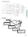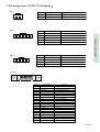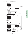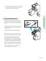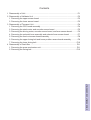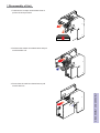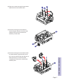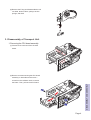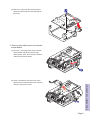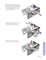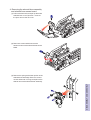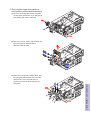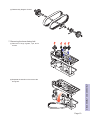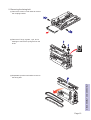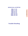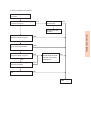
1
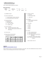
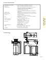
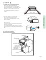
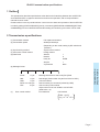
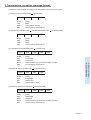
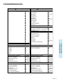
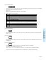
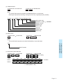
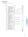
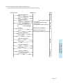
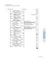
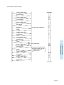
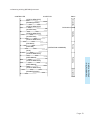
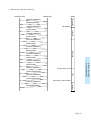
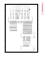
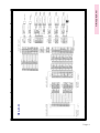
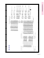
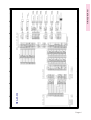
WORLD BILL ACCEPTOR
WBA-24-SS2
WBA-25-SS2
Model Numbers
Specifications
1. Model Classification
How to read the Model Classification Number
Model Numbers
WBA - * * - SS(2) - * * * (*) - * * * - * *
(1)
(2)(3)
(4)
(5)
(6)
(7)(8)(9)
(1) WBA Bill Acceptor
(7) Cash Box Capacity
4 - 400 notes
5 - 500 notes (standard)
A - 1,000 notes
(2) Type of acceptor head
1 - 1x head (magnetic sensors enhanced)
2 - 2x head (optical sensors enhanced)
(8) Faceplate
0 - without faceplate (standard)
1 - with faceplate
(3) Type of CPU board
0 - EPROM (1M)
1 - Flash ROM (1M)
2 & 4 - Flash ROM (4M)
3 & 5 - EPROM (4M)
(4) Type of Cash Box
SS - SS Down Stacker (80mm width)
SS2 - SS2 Down Stacker (82mm width for Euro
banknotes)
(6) Denominations to be accepted
(Example) Euro banknotes
Denomination
Country Code
*
*
*
*
*
*
*
*
*
*
*
*
*
*
*
*
*
*
*
(9) Guide Width
1 - 66mm
2 - 70mm
3 - 76mm
4 - 80mm
5 - 82mm
(10) Interface
01 - ID001: Parallel Interface
02 - ID002: Pulse Interface
03 - ID003: Bidirectional Serial Interface
(standard)
44 - ID044/045: Serial & Pulse Interface
0A2 - ID-0A2: Serial & Pulse Selectable
Interface
(5) Country Code
EUR1
EUR2
EUR3
EUR4
EUR5
(10)
*
*
*
*
*
Contact JCM for other I/F.
*
EXAMPLE
WBA-25-SS2-EUR5-505-03
WBA model bill acceptor for Euro banknotes accepting up to 500 Euro, with 2x head, EPROM, SS2 stacker, 500-note
cash box, 82mm width bill guides and ID-003 I/F without faceplate.
Page 1
2. General Specifications
Refer to the software specifications of each unit.
Refer to the software specifications of each unit.
90% or more (Including the 1st return and 2nd acceptance.
The following bills, however, are excluded.)
a) Dirty, worn, wet, torn, or extremely wrinkled bills.
b) Bill with a folded corner or edge.
c) Bill with a noticeable cutting size difference or printing
displacement.
Within 2 seconds (Time until the output of the vend signal.)
ID-003 bi-directional serial interface (Photocoupler isolation)
Security (lockable) box
Capacity --- Average 500 bills (Coupons)
The lock shall be installed by a user (the catch is supplied
with the unit.)
One bill or one barcode coupon
DC +12V (+-5%), capacity 2.5A or more
Standby status --- 2.8VA
Operation status --- 14VA (MAX. 24VA)
Operating temperature --- 0 oC to 45 oC
Storage temperature --- -20 oC to 60 oC
Relative humidity --- 30% to 80%
No direct sunlight
Refer to the drawing below.
Main unit(with cash box)--- Approx. 4.8 Kg
Cash box alone --- Approx 1.5 Kg
Horizontal and indoor installation
Validation Time:
Standard Interface:
Cash box:
Note:
Escrow:
Power requirements:
Power consumption:
Environment:
Outside dimensions:
Weight:
Installation:
MODEL NUMBERS
SPECIFICATIONS
Accepted Bill Denominations:
Bill insertion:
Acceptance rate:
+0.0
0
2.55
87
93
104.4
3. Dimensions
4.2
6.6
49.8
9.2
6.6
9.2
6.6 27 6.6
225
67
22.2
67
45.8
21.5
50
3.5
2
2-M7
298
155
267
30
202
303.8
6-M4
278
21
10.5
6.6
114
100
100
30
150
Page 2
WBA-12-SS
WBA-13-SS
WBA-22-SS
WBA-23-SS
WBA-24-SS2
WBA-25-SS2
Operation Manual
OPERATION MANUAL
WORLD BILL ACCEPTOR
1. Features ........................................................................................................................ P1
2. Component Names ....................................................................................................... P1
3. DIP Switch Setting ........................................................................................................ P2
4. Installation ..................................................................................................................... P2
5. Input/Output Circuits ..................................................................................................... P3
6. Cabling .......................................................................................................................... P3
7. Pin Assignment ............................................................................................................ P4
8. Operation Flowchart ...................................................................................................... P5
9. Retrieving Bills .............................................................................................................. P6
10. Clearing Bill Jam ......................................................................................................... P6
11. Preventive Maintenance .............................................................................................. P7
OPERATION MANUAL
Contents
1. Features
The WBA has the following features.
· Able to read a wide range of bill sizes
Four types of bill guides are available for the
WBA. Switching the bill guides allows the unit to
read bills ranging from 62mm to 82mm wide.
The length of bills read are from 125mm to
170mm.
62mm - 82mm
OPERATION MANUAL
· DIP switch settings to accept/reject bills
Up to 7 denominations are accepted.
Accept / reject of each denomination is Dipswitch selectable.
· Easy bill retrieval
The cash box can be detached from the main unit to
withdraw deposited bills.
The machine can be equipped with a lock for higher
security. Each SS and SS2 cash box stores up to 500
bills.
2. Component Names
Transport unit
Acceptor head
Bill insertion slot
Acceptor head
release lever
Transport unit
release lever
Cash box release lever
Cash box
Page 1
3. Dipswitch Settings
OPERATION MANUAL
Verify the software in the WBA before installing it. The DIPswitch settings are determined by the software.
See software specifications proivded separately for DIPswitch settings of your software.
OFF 1
2
3
4
5
6
7
8
4. Installation
1. Installation
There are three mounting holes on each side
(a total of six mounting holes).
2. Switching the bill guides
Unless your WBA has been used with another software before,
correct bill guides should be installed in the acceptor unit .
Each software has designated bill guide types (ex. USA = 66mm
width = Type 1 Bill Guide, EUR5 = 82mm width = Type 5 Bill Guide).
Refer to the software specification to find which bill guide should be
installed.
To remove the bill guides, first remove the acceptor head from the
main unit and then push out the bill guides from the back of the
acceptor head with a Phillips-head screwdriver. To install the bill
guides, push the guides into the acceptor head slot from the front
until you hear a click. Be sure to push the guides in the correct
direction.
Page 2
OPERATION MANUAL
5. Input/Output Circuits
6. Cabling
External harness
External connector
Socket
DR1-12-2SCFO(JAE)
Contact DR-SC24-7000(JAE)
External connector (CN1)
Housing 51030-0230(MOLEX)
Contact 50083-8 14(MOLEX)
(AWG #24~#30)
*
External connector (CN2)
Housing 51030-0530(MOLEX)
Contact 50083-8 14(MOLEX)
(AWG #24~#30)
External connector (CN3)
Housing 51030-0430(MOLEX)
Contact 50083-8 14(MOLEX)
(AWG #24~#30)
*
*
Page 3
7. Pin Assignment - ID-003 I/F (Standard)
CN 1
4
3
2
1
CN 3
4
Connector
Function
DC +12V power supply
Ground
Pin No.
1
2
3
4
5
Signal Name
M. RES
TXD
+ 12V
RXD
GND
Function
Acceptor reset signal
Data transmission
Interface Power supply (DC+12V)
Data reception
Ground
Pin No.
1
2
3
4
Signal Name
LED +
LED NC
NC
Function
LED drive (anode)
LED drive (cathode)
Reserved
Reserved
1
CN 2
5
Signal Name
+ 12V
GND
3
2
1
1
7
14
20
Pin No.
1
2
3
4
5
6
7
8
9
10
11
12
13
14
15
16
17
18
19
20
Signal Name
+ 12V
GND
M. RES
TXD
+ 12V
RXD
GND
NC
NC
NC
NC
NC
GND
LED +
NC
NC
NC
LED NC
NC
OPERATION MANUAL
2
Pin No.
1
2
Function
DC +12V power supply
Ground
Acceptor reset signal
Data transmission
Interface Power supply (DC+12V)
Data reception
Ground
Do not use this pin
Do not use this pin
Do not use this pin
Do not use this pin
Do not use this pin
Ground
LED Drive (Anode)
Do not use this pin
Do not use this pin
Do not use this pin
LED Drive (Cathode)
Do not use this pin
Do not use this pin
Page 4
8. Operation Flowchart - ID-003 I/F (Standard)
POWER ON
CPU.ROM.RAM
TEST
NO
OK
YES
TEST MODE
YES
STOP
NO
VALI.STACKER
TEST
TEST MODE
NO
OK
YES
A
UNEXPECTED
SENSOR ON
NO
ENABLE
YES
REJECT
NO
YES
NO(JAM)
OK
LED ON
NO
OPERATION MANUAL
STAND-BY
LED OFF
BILL
INSERTED
YES
A
YES
A
MOTOR FWD
DATASAMPLING
START
ILLEGAL
DATA/CONDITION
YES
NO
SAMPLING
END
YES
MOTOR STOP
VALIDATE
SAMPLING
DATA
NO
INHIBIT
CONDITION
YES
OK
B
NO
BILL REJECT
CREDIT OUTPUT
BILL FEED OUT
TO STACKER
FEED OK
OK
NO
VEND OUTPUT
YES
BILL
REMOVED
NO
YES
FULL ON
A
LED OFF
B
FULL
BILL STACK
STACK
COMPLETE
NO(JAM)
NO
A
LED OFF
STOP
Page 5
1. Push the release lever down and pull the
cash box forward.
OPERATION MANUAL
9. Retrieving Bills
2. Open the cash box cover and remove
the bills.
10. Clearing Bill Jam
1. Pull the tabs on both sides of the acceptor
forward to open the acceptor head. Remove
the jammed bill.
2. If the jammed bill cannot be removed by
opening the acceptor, pull the transport unit
open/close lever to open the transport cover
and remove the jammed bill.
Page 6
OPERATION MANUAL
3. When a bill is jammed near the inlet of the cash
box, push the release lever down to pull out the
cash box and remove the jammed bill.
11. Preventive Maintenance
It is important to keep the bill path, rollers, and
belts clean. The sensor lenses are transparent,
and made of polymer material. Handle them with
care.
To clean the lenses, use a lint-free cloth and mild
non-abrasive detergent such as liquid dish soap
mixed with water.
Do not use alcohol or thinner for cleaning.
Note: JCM does not recommend cleaning cards,
cleaning pads, or cleaning solutions of any kind.
Cash box Preventive Maintenance (P/M)
Do periodic P/M on the cash boxes to ensure
proper operation. Use compressed air to blow
out the paper fibers and other debris that builds
up over time. Check the belts and all moving
parts for wear and proper positioning. If the unit
does not operate properly, it can cause bill jams.
After completing the P/M, Auto-Calibration is
recommended (Refer to Chapter 7).
Page 7
ID-003 Communication
Specifications
COMMUNICATION
SPECIFICATIONS
WORLD BILL ACCEPTOR
WBA-12-SS
WBA-13-SS
WBA-22-SS
WBA-23-SS
WBA-24-SS2
WBA-25-SS2
Contents
1
2
3
4
5
6
Outline ............................................................................................................................. 1
Transmission specifications ............................................................................................. 1
Transmission, reception message format ......................................................................... 2
Communication flow ......................................................................................................... 3
Command/response list ................................................................................................... 5
Command/response details ............................................................................................. 6
6-1 Status request (CONTROLLER
ACCEPTOR) .................................................... 6
6-2 Status (ACCEPTOR
CONTROLLER) ................................................................. 6
6-2-1 Nomal status (ACCEPTOR
CONTROLLER) ............................................. 6
6-2-2 Power up status (ACCEPTOR
CONTROLLER) ........................................ 9
6-2-3 Error status (ACCEPTOR
CONTROLLER) ............................................. 10
6-3 Operation command (CONTROLLER
ACCEPTOR) ......................................... 10
6-4 ACK (Affirmative response) ..................................................................................... 11
6-5 Seetting command (CONTROLLER
6-6 Setting status request (CONTROLLER
ACCEPTOR) ........................................... 12
ACCEPTOR) ....................................... 13
7-2 Accepting of bills ..................................................................................................... 19
7-3 Rejection of bills by validating .................................................................................. 22
7-4 Returning of bills by [ RETURN ] command ............................................................... 23
7-5 Inhibit of accepting by acceptor ................................................................................ 24
7-6 Stacker full (STACK-1)............................................................................................. 25
7-7 Bill jamming when returning ...................................................................................... 26
COMMUNICATION
SPECIFICATIONS
6-7 Data (Setting status/setting command) .................................................................... 15
7 Timing chart ................................................................................................................... 17
7-1 Power up ................................................................................................................. 17
ID-003 Communication specifications
1 Outline
This specification describes specifications at the data level of interfacing between the ACCEPTOR
and CONTROLLER. In regard to electrical connections and operation, refer to the specification
manuals for each model.
ID-003 interface is a 2-way serial interface. Control over the status and operation of the ACCEPTOR
is made by polling [STATUS REQUEST] and by commands ([OPERATION COMMAND] [SETTING
COMMANDS]) from the CONTROLLER and also setting and confirming of functions can be made.
2 Transmission specifications
(1) Transmission method
(2) Transmission speed
Full duplex transmission
9600 bps/19200 bps
(Depending on the model, setting by DIP switches is
possible.)
Asynchronous method
Polling method
Start bit
1
Data bit
8
Parity bit
EVEN
Stop bit
1
X parameter
None
(3) Synchronizing method
(4) Connection control method
(5) Data fornat
SYNC
LNG
SYNC
1 byte
LNG
1 byte
CMD
1 byte
DATA 0 to 250 byte
CRC
2 byte
(7)
Error control method
CMD
:
:
:
:
:
DATA
COMMUNICATION
SPECIFICATIONS
(6) Message format
CRC
Message transmission start code [FCH] fixed
Data length (Total number of bytes from SYNC to CRC)
Command status
Data necessary for command (omitted by CMD)
Check code by CRC method
Object secion to be from SYNC to end of DATA
(Inttial value = 0)
Error detection
CRC method
CRC - CCITT
P(x) = X16+X12+X5+1
Page 1
3 Transmission, reception message format
Transmission and reception message format is divided into the following five types.
(1) Polling format (CONTROLLER
LNG
CMD
CRC
SYNC
:
[FCH]
LNG
:
[05H]
CMD
CRC
:
:
[11H] (Status request)
Check code by CRC method
(2) ACK format (CONTROLLER
SYNC
LNG
ACCEPTOR/ACCEPTOR
CMD
CRC
SYNC
LNG
CMD
:
:
:
[FCH]
[05H]
[50H]
CRC
:
Check code by CRC method
(3) Command format (CONTROLLER
SYNC
LNG
CONTROLLER)
ACCEPTOR)
CMD
DATA
CRC
SYNC
LNG
:
:
[FCH]
Data length
CMD
DATA
CRC
:
:
:
Command
Data necessary for command (Omitted by CMD)
Check code by CRC method
(4) Response format I (ACCEPTOR
SYNC
SYNC
LNG
SST
CRC
LNG
:
:
:
:
CONTROLLER)
SST
CRC
[FCH]
Data length
Status code
Check code by CRC
(5) Response format II (ACCEPTOR
SYNC
COMMUNICATION
SPECIFICATIONS
SYNC
ACCEPTOR)
LNG
CONTROLLER)
CMD
DATA
CRC
SYNC
:
[FCH]
LNG
CMD
:
:
Data length
Response
DATA
CRC
:
:
Data necessary for command (Omitted by CMD)
Check code by CRC method
Page 2
4 Communication flow
(1) Transmission of STATUS REQUEST
CONTROLLER
ACCEPTOR
[STATUS REQUEST]
Polling frequency
100ms to 200ms
STATUS
Respons time
within 50 ms
(2) Transmission command to ACCEPTOR
CONTROLLER
ACCEPTOR
OPERATION COMMAND
[ACK]
Respons time
within 50 ms
(3) Communication error 1
(Failure of communication system and power source OFF, failure etc. of acceptor)
CONTROLLER
ACCEPTOR
[STATUS REQUEST]
STATUS
[STATUS REQUEST]
STATUS
*)No response within 50 ms,
or transmission made again
to ACCEPTOR for 3 seconds
but no response received.
Communication error 2
(Failure etc. of communication system)
CONTROLLER
ACCEPTOR
[STATUS REQUEST]
*)ACCEPTOR unable to
receive data within 200 ms.
COMMUNICATION
SPECIFICATIONS
[STATUS REQUEST]
Communication error 3
CONTROLLER
ACCEPTOR
[STATUS REQUEST]
[COMMUNICATION ERROR]
[STATUS REQUEST]
*)CRC error, loss of data
etc. occurs.
[COMMUNICATION ERROR]
Communication error 4
CONTROLLER
ACCEPTOR
OPERATION COMMAND
[INVALID COMMAND]
OPERATION COMMAND
*)Improper command received
in processing action of
ACCEPTOR.
[INVALID COMMAND]
Page 3
5 Command/response list
RESPONSE TO [VEND VALID]
ACK
OPERATION COMMAND
RESET
STACK-1
STACK-2
RETURN
HOLD
WAIT
SETTING COMMAND
ENABLE/DISABLE (DENOMI)
SECURITY (DENOMI)
INHIBIT (ACCEPTOR)
DIRECTION
OPTIONAL FUNCTION
SETTING STATUS REQUEST
ENABLE/DISABLE (DENOMI)
SECURITY (DENOMI)
INHIBIT (ACCEPTOR)
DIRECTION
OPTIONAL FUNCTION
VERSION REQUEST
BOOT VERSION REQUEST
11H
ACCEPTOR
CONTROLLER
STATUS
ENABLE (IDLING)
ACCEPTING
ESCROW
STACKING
VEND VALID
STACKED
REJECTING
RETURNING
HOLDING
DISABLE (INHIBIT)
INTIALIZE
POWER UP STATUS
POWER UP
POWER UP WITH BILL IN ACCEPTOR
POWER UP WITH BILL IN STACKER
ERROR STATUS
STACKER FULL
STACKER OPEN
JAM IN ACCEPTOR
JAM IN STACKER
PAUSE
CHEATED
FAILURE
COMMUNICATION ERROR
11H
12H
13H+DATA
14H
15H
16H
17H+DATA
18H
19H
1AH
1BH
40H
41H
42H
43H
44H
45H
46H
47H
48H
49H+DATA
4AH
50H
40H
41H
42H
43H
44H
45H
C0H+DATA
C1H+DATA
C3H+DATA
C4H+DATA
C5H+DATA
80H
81H
83H
84H
85H
88H
89H
COMMUNICATION
SPECIFICATIONS
CONTROLLER
ACCEPTOR
STATUS
STATUS REQUEST
RESPONSE TO OPERATION COMMAND
50H
ACK
4BH
INVALID COMMAND
RESPONSE TO SETTING COMMAND
ENABLE/DISABLE (DENOMI)
SECURITY (DENOMI)
INHIBIT (ACCEPTOR)
DIRECTION
OPTIONAL FUNCTION
SETTING STATUS
ENABLE/DISABLE (DENOMI)
SECURITY (DENOMI)
INHIBIT (ACCEPTOR)
DIRECTION
OPTIONAL FUNCTION
VERSION INFORMATION
BOOT VERSION REQUEST
C0H+DATA
C1H+DATA
C3H+DATA
C4H+DATA
C5H+DATA
80H+DATA
81H+DATA
83H+DATA
84H+DATA
85H+DATA
88H+DATA
89H+DATA
Page 4
6 Command/response details
6-1 STATUS REQUEST (CONTROLLER
ACCEPTOR)
Request from CONTROLLER to ACCEPTOR on status of ACCEPTOR
By the [STATUS REQUEST], the CONTROLLER monitors operation status, resetting from error
status etc. of the ACCEPTOR.
Response : Status response
[11H] : STATUS REQEST
11H
a. Frequency of polling shall be 100 msec to 200 msec.
b. Response time of the ACCEPTOR shall be within 50 msec.
c. The CONTROLLER must resend the message in case a communication error response is
received and when a response is not received within 200 msec.
(Refer to 4-(3))
6-2 STATUS (ACCEPTOR
CONTROLLER)
Response in reply to [STATUS REQUEST] from the CONTROLLER
Expresses the present status of the ACCEPTOR which is normally divided into normal status,
power-up status and error status.
6-2-1 Normal status (ACCEPTOR
CONTROLLER)
(1) [11H] : ENABLE (IDLING)
COMMUNICATION
SPECIFICATIONS
11H
Bill accepting standby and operation able status
(2) [12H] : ACCEPTING
12H
Status in which bills are taken in and validating is being conducted
Page 5
(3) [13H] : ESCROW
13H
DATA
Status in which bill validation is completed and command from the CONTROLLER is awaited (The bill is held
inside the ACCEPTOR).
[ESCROW DATA] (accepted denomination) of 1 byte is added.
If [STATUS REQUEST] cannot be received from the ACCEPTOR within 3 seconds while in the [ESCROW]
status, and when an operation command from the CONTROLLER is not transmitted within 10 seconds after
transmission, the bill is returned.
ESCROW DATA (Accepted denomination)
DATA
Denomination
61h
01
62h
02
63h
03
64h
04
65h
05
66h
06
67h
07
68h
08
)
The
accepted
denominations are described in the [DATA setting specifications]
*
for each model.
(4) [14H] : STACKING
Status in which bills are conveyed to the stacker and stored in accordance with OPERATION COMMANDs
[STACK-1] and [STACK-2] from the CONTROLLER.
(Refer to 6-3, 7-2)
(5) [15H] : VEND VALID
15H
Confirming signal of bill acceptance
Against [VEND VALID], the ACCEPTOR holds its status until [ACK] is sent from the CONTROLLER.
The CONTROLLER conducts credit up by [VEND VALID].
(Refer to 7-2)
(6) [16H] : STACKED
16H
Status from the time bill is stored up to the time accepting of the next bill from [VEND VALID] becomes
possible ([ENABLE] status).
Page 6
COMMUNICATION
SPECIFICATIONS
14H
(7) [17H] : REJECTING
17H
DATA
A Status in which unacceptable bills as the result of bill validating by the ACCEPTOR or bills by an [INHIBIT]
command from the CONTROLLER are returned.
(Refer to 7-3)
[REJECT DATA] (description of rejection) of 1 byte is added.
REJECT DATA (Rejection description)
DATA
Description
71h
Insertion error
72h
Mag srror
73h
Rejection action by remaining of bills etc. (ACCEPTOR head section)
74h
Compensation error multiplying factor error
75h
Conveying error
76h
Denomination assessing error
77h
Photo pattern error 1
78h
Photo level error
79h
Return by inhibit/insertion direction, denomination error
In case a command against escrow is not transmitted
7Ah
7Bh
Operation error
7Ch
Rejecting action by remaining of bills and such (stacker section)
7Dh
Length error
7Eh
Photo pattern error 2
(8) [18H] : RETURNING
Against [ESCROW], a status in which a bill is returned by a [RETURN] command from the CONTROLLER.
(Refer to 7-4)
(9) [19H] : HOLDING
19H
Against [ESCROW], a status in which a bill is held inside the ACCEPTOR by a [HOLD] command from the
CONTROLLER.
(10) [1AH] : DISABLE (INHIBIT)
1AH
A Status in which acceptance of bills by the ACCEPTOR is inhibited by a [INHIBIT]
command from the CONTROLLER.(Refer to 7-5)
Also a status in which all acceptable denominations are in a disable status by [ENABLE/DISABLE]
command or where all receiving directions are in an inhibit status by a [DIRECTION] command.
Page 7
COMMUNICATION
SPECIFICATIONS
18H
(11) [1BH] : INITIALIZE
1BH
Status in which the ACCEPTOR is conducting initializing action by [RESET] from the CONTROLLER.
The setting command from the CONTROLLER is effective only in this status. (Refer to 7-1)
6-2-2 Power up status (ACCEPTOR
CONTROLLER)
By the power supply ON status, the ACCEPTOR returns the following status.
Also, this status is held until a [RESET] command is sent from the CONTROLLER. (Refer to 7-2)
(1) [40H] : POWER UP
40H
A status in which status inside the ACCEPTOR is normal with the ACCEPTOR power on
(2) [41H] : POWER UP WITH BILL IN ACCEPTOR
41H
A status in which bills remain in the ACCEPTOR head conveying section (a return possible position) with the
power supply on.
By a [RESET] command from the CONTROLLER, the ACCEPTOR returns the bill and conducts initializing.
(3) [42H] : POWER UP WITH BILL IN STACKER
A status in which bills remain in the stacker conveying section (a return possible position) with the power
supply on.
By a [RESET] command from the CONTROLLER, the ACCEPTOR stores the bill and conducts initializing.
Page 8
COMMUNICATION
SPECIFICATIONS
42H
6-2-3 Error status (ACCEPTOR
CONTROLLER)
Method for releasing error status differs by model.
For details, refer to the [Specification manual] and [DATA setting specification manual] by model.
(1) [43H] : STACKER FULL
43H
A stacker box full condition (Refer to 7-6)
(2) [44H] : STACKER OPEN (STACKER BOX REMOVE)
44H
The stacker door is open or the stacker box is not mounted.
(3) [45H] : JAM IN ACCEPTOR
45H
Jamming has occurred inside the ACCEPTOR.
(4) [46H] : JAM IN STACKER
46H
(5) [47H] : PAUSE
47H
A condition in which the ACCEPTOR cannot operate because a second bill has been inserted while the first
bill is being stored or conveyed
(When the second bill is removed, conveying is started.)
(6) [48H] : CHEATED
48H
An action thought to be mischievous against the ACCEPTOR has been committed.
Page 9
COMMUNICATION
SPECIFICATIONS
Jamming has occurred in the stacker conveying section.
An abnormal condition has developed at the time of storing.
(7) [49H] : FAILURE
49H
DATA
A status in which normal operation cannot be made because of a failure, an abnormal condition, or incorrect
setting of the ACCEPTOR.
[FAILURE DATA] of 1 byte are added.
FAILURE DATA ( abnormal contents )
DATA
Contents
A2h
Stack motor failure
A5h
Transport ( feed ) motor speed failure
A6h
Transport ( feed ) motor failure
ABh
Cash box not ready
AFh
Validator head remove
B0h
Boot ROM failure
B1h
External ROM failure
B2h
ROM failure
B3h
External ROM writing failure
(8) [4AH] : COMMUNICATION ERROR
4AH
An error has developed in the communication data. (Refer to 4-(3)- 3 )
(9) [4BH] : INVALID COMMAND
COMMUNICATION
SPECIFICATIONS
4BH
Command from the CONTROLLER is not valid. (Refer to 4-(3)- 4 )
6-3 OPERATION COMMAND (CONTROLLER
ACCEPTOR)
Operation command from the CONTROLLER to the ACCEPTOR
Response : ACK response
(1) [40H] : RESET
40H
A command for resetting the ACCEPTOR. The ACCEPTOR accepts this command regardless of its status.
After the power supply is turned on (power up status), transmission is required without fail.
(2) [41H] : STACK-1
41H
A bill in an escrow status is conveyed to the stacker section and stored.
The ACCEPTOR becomes in a [VEND VALID] status when the bill passes the stacker lever.
Valid only when in [ESCROW] status
* ) The position of STACK-1 may differ by model.
Page 10
(3) [42H] : STACK-2
42H
A bill in escrow status is conveyed to the stacker and stored.
The ACCEPTOR becomes in a [VEND VALID] status when a bill is stored. (Pushed in position)
Valid only when in [ESCROW] status.
* ) The position of STACK-2 may differ by model.
(4) [43H] : RETURN
43H
Returns a bill in an escrow status.
Valid on when in [ESCROW] status
(5) [44H] : HOLD
44H
A bill in escrow status is made to be held for 10 seconds. For continued holding, resending of a
[HOLD] command is necessary.
Valid only when in [ESCROW] status
(6) [45H] : WAIT
45H
COMMUNICATION
SPECIFICATIONS
Status of ACCEPTOR is made to be held for 3 seconds. To continued holding this status,
resending of a
[WAIT] command is necessary.
6-4 ACK (Affirmative response)
[50H] : ACK
50H
[ACCEPTOR
CONTROLLER]
Response against an [OPERATION COMMAND] from the CONTROLLER.
[CONTROLLER
ACCEPTOR]
Response against [VEND VALID] from the ACCEPTOR.
Page 11
6-5 SETTING COMMAND (CONTROLLER
ACCEPTOR)
A command to set (change) function of the ACCEPTOR by the CONTROLLER.
Setting of each denomination is made by the respective bits of data of 2 bytes to be added.
Receiving is possible only when ACCEPTOR is initialized. (However INHIBIT is excluded.)
(1) [C0H] : ENABLE/DISABLE
C0H
DATA
Accepting by each denomination is set.
[ENABLE/DISABLE DATA] of 2 bytes are added. (Refer to 6-7-(1))
Response : ECHO BACK (ACCEPTOR
C0H
CONTROLLER)
DATA
(2) [C1H] : SECURITY
C1H
DATA
Validating level by each denomination is set.
[SECURITY DATA] of 2 bytes is added. (Refer to 6-7-(2))
Response : ECHO BACK (ACCEPTOR
CONTROLLER)
C1H
DATA
(3) [C3H] : INHIBIT
C3H
DATA
C3H
COMMUNICATION
SPECIFICATIONS
Status of ACCEPTOR is temporarily made acceptance inhibit.
[INHIBIT DATA] of 1 byte are added. (Refer to 6-7-(3))
Response : ECHO BACK (ACCEPTOR
CONTROLLER)
DATA
* INHIBIT can be accepted in any status.
Set during acceptance of bill
Set during validating of bill
Set while in escrow status
Set during storing of bill
Set while in vend valid
Return bill and becomes
in INHIBIT status.
After storing bill,
becomes in INHIBIT status.
(4) [C4H] : DIRECTION
C4H
DATA
Sets accepting direction of bill.
[DIRECTION DATA] of 1 byte are added. (Refer to 6-7-(4))
Response : ECHO BACK (ACCEPTOR
C4H
CONTROLLER)
DATA
Page 12
(5) [C5H] : OPTIONAL FUNCTION
C5H
Sets option function of ACCEPTOR.
[OPTIONAL FUNCTION DATA] of 2 bytes is added. (Refer to 6-7-(7))
Response : ECHO BACK (ACCEPTOR
CONTROLLER)
C5H
DATA
6-6 SETTING STATUS REQUEST (CONTROLLER
ACCEPTOR)
By a [SETTING] command, the CONTROLLER requests transmission of the set status of the ACCEPTOR.
(1) [80H] : ENABLE/DISABLE
80H
Transmission request for set acceptance status of acceptor by each denomination.
Response : SETTING STATUS (ACCEPTOR
CONTROLLER)
[ENABLE/DISABLE] commands as well as status of accepting denominations set by DIP
switches are added as [ENABLE/DISABLE DATA] of 2 bytes. (Refer to 6-7-(1))
80H DATA
)
Settings
of
DIP switches are described in the [Specification manual] for each model.
*
(2) [81H] : SECURITY
81H
COMMUNICATION
SPECIFICATIONS
Request for transmission of set status of validating level by each denomination.
Response : SETTING STATUS (ACCEPTOR
CONTROLLER)
[SECURITY DATA] of 2 bytes are added. (Refer to 6-7-(2))
81H
DATA
(3) [83H] : INHIBIT
83H
Transmission request for set status of acceptance inhibit of the ACCEPTOR.
Response : SETTING STATUS (ACCEPTOR
CONTROLLER)
[INHIBIT DATA] of 1 byte are added. (Refer to 6-7-(3))
83H
DATA
(4) [84H] : DIRECTION
84H
Request for transmission of set status of bill acceptance direction.
Response : SETTING STATUS (ACCEPTOR
CONTROLLER)
[DIRECTION DATA] of 1 byte are added. (Refer to 6-7-(4))
84H
DATA
Page 13
(5) [88H] : VERSION REQUEST
88H
Request for transmission of ACCEPTOR MODEL ID VERSION.
Response : SETTING STATUS (ACCEPTOR
CONTROLLER)
ASCII data of 36 bytes are added. (Refer to 6-7-(5))
88H
DATA
(6) [89H] : BOOT VERSION REQUEST
89H
Request for transmission of BOOT VERSION of ACCEPTOR.
Response : SETTING STATUS (ACCEPTOR
CONTROLLER)
ASCII data of 4 bytes are added. (Refer to 6-7-(6))
89H
DATA
(7) [85H] : OPTIONAL FUNCTION
85H
Request for transmission of setting status of [OPTIONAL FUNCTION] command.
Response : SETTING STATUS (ACCEPTOR
CONTROLLER)
[OPTIONAL FUNCTION DATA] of 2 bytes are added. (Refer to 6-7-(7))
DATA
COMMUNICATION
SPECIFICATIONS
85H
Page 14
6-7 DATA (SETTING STATUS/SETTING COMMAND)
Data formats for SETTING STATUS and SETTING COMMANDS are described.
For details, refer to [DATA setting specifications] for each model.
(1) ENABLE/DISABLE DATA
CONTROLLER
ACCEPTOR
C0h + DATA1 + DATA2
80h
DATA1
DATA2
bit7
08
bit7
0
bit6
07
bit6
0
bit5
06
bit5
0
ACCEPTOR
CONTROLLER
C0h + DATA1 + DATA2 [echo back]
80h + DATA1 + DATA2
bit4
bit3
bit2
bit1
05
04
03
02
bit4
bit3
bit2
bit1
0
0
0
0
0 : enable
1 : disable (default : 00h)
bit0
01
bit0
0
Denomination
(2) SECURITY DATA
CONTROLLER
ACCEPTOR
C1h + DATA1 + DATA2
81h
DATA1
DATA2
bit7
08
bit7
0
bit6
07
bit6
0
bit5
06
bit5
0
ACCEPTOR
CONTROLLER
C1h + DATA1 + DATA2 [echo back]
81h + DATA1 + DATA2
bit4
bit3
bit2
bit1
bit0
05
04
03
02
01
bit4
bit3
bit2
bit1
bit0
0
0
0
0
0
0 : normal
1 : security level hight (default : 00h)
Denomination
CONTROLLER
ACCEPTOR
C3h + DATA (1byte)
83h
DATA
bit7
0
bit6
0
bit5
0
COMMUNICATION
SPECIFICATIONS
(3) INHIBIT DATA
ACCEPTOR
CONTROLLER
C3h + DATA (1byte) [echo back]
83h + DATA (1byte)
bit4
bit3
bit2
bit1
0
0
0
0
0 : not inhibit
1 : inhibit (default : 01h)
bit0
inh
(4) DIRECTION DATA
CONTROLLER
ACCEPTOR
C4h + DATA (1byte)
84h
DATA
bit7
0
bit6
0
bit5
0
ACCEPTOR
CONTROLLER
C4h + DATA (1byte) [echo back]
84h + DATA (1byte)
bit4
bit3
0
04
0 : not inhibit
1 : inhibit
bit2
03
bit1
02
bit0
01
Direction
Page 15
(5) VERSION DATA
CONTROLLER
88h
ACCEPTOR
ACCEPTOR
88h + DATA
CONTROLLER
DATA
The ACCEPTOR responds to MODEL/ID/VERSION/CRS etc. by ASCII data.
Data length expresses the following meanings from the top, as ([LNG]-5) bytes (variable).
"x (xxx) - xx - xx ID003 - xxvxxx-xx ddmmmyy xxxx"
CRC check code
Date Mar. 12, 2003
Software version
"12MAR03"
Interface type
Stacker type
Model No.
Country code
Model code
(6) BOOT DATA
CONTROLLER
89h
ACCEPTOR
ACCEPTOR
CONTROLLER
89h + DATA (4byte)
DATA
The ACCEPTAOR responds to the BOOT VERSION by 4 byte ASCII data.
COMMUNICATION
SPECIFICATIONS
"Bxx"
BOOT version
(7) OPTIONAL FUNCTION DATA
CONTROLLER
ACCEPTOR
C5h + DATA1 + DATA2
85h
DATA1
DATA2
bit7
08
bit7
0
bit6
07
bit6
0
bit5
06
bit5
0
ACCEPTOR
CONTROLLER
C5h + DATA1 + DATA2 [echo back]
85h + DATA1 + DATA2
bit4
bit3
bit2
bit1
05
04
03
02
bit4
bit3
bit2
bit1
0
0
0
0
0 : disable
1 : enable (default : 00h)
bit0
01
bit0
0
OPTION
Page 16
7 Timing chart
7-1 POWER UP
(1) From charging of power supply to standby status
CONTROLLER
ACCEPTOR
Status
[STATUS REQUEST]
[STATUS REQUEST]
Power supply charged
[VERSION REQUEST]
(SETTING REQUEST)
[VERSION INFORMATION]
[RESET]
(OPERATION COMMAND)
Power supply on
[POWER UP]
Power supply
cut
[STATUS REQUEST]
[ACK]
[STATUS REQUEST]
[INITIALIZE]
[ENABLE/DISABLE]
(SETTING COMMAND)
[SECURITY]
[SECURITY]
[OPTIONAL FUNCTION]
(SETTING COMMAND)
Initializing
(SETTING COMMAND)
COMMUNICATION
SPECIFICATIONS
[ENABLE/DISABLE]
[OPTIONAL FUNCTION]
[INHIBIT]
(SETTING COMMAND)
[INHIBIT]
[STATUS REQUEST]
[INITIALIZE]
[STATUS REQUEST]
On standby
[ENABLE](IDLING)
Page 17
(2) From charging of power supply to standby status
When bill remains inside the ACCEPTOR at the time of power charging
CONTROLLER
ACCEPTOR
Status
[STATUS REQUEST]
[STATUS REQUEST]
IN ACCEPTOR]
[POWER UP WITH BILL
IN STACKER]
[RESET]
[ACK]
Bill remains
in a return possible position.
(Bill remains
in a return impossible position.)
(OPERATION COMMAND)
Power supply on
[POWER UP WITH BILL
Power supply charged
Power supply
cut
[STATUS REQUEST]
Bill is returned (stored) by
initializing by [RESET] command.
[STATUS REQUEST]
[INITIALIZE]
COMMUNICATION
SPECIFICATIONS
[INITIALIZE]
Initializing
[STATUS REQUEST]
[STATUS REQUEST]
[INITIALIZE]
[ENABLE](IDLING)
On standby
[STATUS REQUEST]
Page 18
7-2 Accepting of bill
(1) Accepting of bill by [STACK-1] command
CONTROLLER
ACCEPTOR
Status
On standby
[STATUS REQUEST]
[ENABLE](IDLING)
[STATUS REQUEST]
Bill insertion
[ACCEPTING]
Validating
[STATUS REQUEST]
[ACCEPTING]
[STATUS REQUEST]
[ESCROW]
[ACK]
[STATUS REQUEST]
Bill is returned if
no [OPERATION COMMAND]
is made within 10 seconds
against [ESCROW].
Feed
[STACKING]
(OPERATION COMMAND)
Escrow
[STACK-1]
Bill is returned if
no [STATUS REQUEST] is
made within 3 seconds while
in ESCROW status.
COMMUNICATION
SPECIFICATIONS
[STATUS REQUEST]
[VEND VALID]
VEND
VALID
[ACK]
[STATUS REQUEST]
[STACKED]
Storing
[STATUS REQUEST]
[STACKED]
[STATUS REQUEST]
On standby
[ENABLE](IDLING)
Page 19
(2) Accepting of bill by [STACK-2] command
CONTROLLER
ACCEPTOR
Status
On standby
[STATUS REQUEST]
[ENABLE](IDLING)
[STATUS REQUEST]
Bill insertion
[ACCEPTING]
Validating
[STATUS REQUEST]
[ACCEPTING]
[STATUS REQUEST]
[ESCROW]
(OPERATION COMMAND)
Escrow
[STACK-2]
[ACK]
[STATUS REQUEST]
Feed
[STACKING]
[STATUS REQUEST]
[ACK]
VEND
VALID
[VEND VALID]
COMMUNICATION
SPECIFICATIONS
[STATUS REQUEST]
Storing
[STACKING]
[STATUS REQUEST]
[STATUS REQUEST]
On standby
[ENABLE](IDLING)
Storing
[STACKED]
Page 20
(3) Resending of [VEND VALID]
[STATUS REQUEST]
[ACCEPTING]
Validating
[STATUS REQUEST]
[ACCEPTING]
[STATUS REQUEST]
[ESCROW]
(OPERATION COMMAND)
Escrow
[STACK-1]
[ACK]
[STATUS REQUEST]
Feed
[STACKING]
[STATUS REQUEST]
[VEND VALID]
[ACK]
[ACK]
COMMUNICATION
SPECIFICATIONS
[VEND VALID]
NO RESPONSE
VEND
VALID
[STATUS REQUEST]
Resending of [VEND VALID]
Against [VEND VALID],
status is held unitl
[ACK] is sent.
[STATUS REQUEST]
[STATUS REQUEST]
Storing
[STACKED]
[STACKED]
Page 21
7-3 Return of bill by validating
CONTROLLER
ACCEPTOR
Status
On standby
[STATUS REQUEST]
[ENABLE](IDLING)
[STATUS REQUEST]
Bill insertion
[ACCEPTING]
[ACCEPTING]
Validating
[STATUS REQUEST]
[STATUS REQUEST]
[REJECTING]
[REJECTING]
Returning
[STATUS REQUEST]
[STATUS REQUEST]
COMMUNICATION
SPECIFICATIONS
On standby
[ENABLE](IDLING)
Page 22
7-4 Returning of bill by [RETURN] command
CONTROLLER
ACCEPTOR
Status
On standby
[STATUS REQUEST]
[ENABLE](IDLING)
[STATUS REQUEST]
Bill insertion
[ACCEPTING]
Validating
[STATUS REQUEST]
[ACCEPTING]
[STATUS REQUEST]
[ESCROW]
(OPERATION COMMAND)
Escrow
[RETURN]
[ACK]
[STATUS REQUEST]
COMMUNICATION
SPECIFICATIONS
[STATUS REQUEST]
Returning
[RETURNING]
[RETURNING]
[ENABLE](IDLING)
On standby
[STATUS REQUEST]
Page 23
7-5 Inhibit of accepting by ACCERTOR
CONTROLLER
ACCEPTOR
Status
[STATUS REQUEST]
[ENABLE](IDLING)
On standby
[STATUS REQUEST]
[ENABLE](IDLING)
[INHIBIT]
[INHIBIT]
(SETTING COMMAND)
(SETTING STATUS)
[STATUS REQUEST]
[STATUS REQUEST]
Inhibit
[DISABLE](INHIBIT)
COMMUNICATION
SPECIFICATIONS
[DISABLE](INHIBIT)
Page 24
7-6 Stacker full (STACK-1)
CONTROLLER
ACCEPTOR
Status
[ENABLE](IDLING)
[STATUS REQUEST]
Bill insertion
[ACCEPTING]
Validating
On standby
[STATUS REQUEST]
VEND
VALID
[VEND VALID]
[ACK]
[STATUS REQUEST]
[STACKED]
[STATUS REQUEST]
Storing
[STACKED]
[STATUS REQUEST]
COMMUNICATION
SPECIFICATIONS
[STACKER FULL]
[STATUS REQUEST]
[STACKER FULL]
[STATUS REQUEST]
Extracting of bill
[STATUS REQUEST]
Initializing
[INITIALIZE]
[INITIALIZE]
[STATUS REQUEST]
On standby
[DISABLE](INHIBIT)
* Releasing method of [STACKER FULL] status differsby model.
Page 25
7-7 Bill jamming at the time of returning
CONTROLLER
ACCEPTOR
Status
On standby
[STATUS REQUEST]
[ENABLE](IDLING)
[STATUS REQUEST]
Bill insertion
Validating
[ACCEPTING]
[STATUS REQUEST]
[ACCEPTING]
[STATUS REQUEST]
[REJECTING]
[STATUS REQUEST]
Returning
[REJECTING]
[STATUS REQUEST]
[REJECTING]
COMMUNICATION
SPECIFICATIONS
[STATUS REQUEST]
[REJECTING]
[STATUS REQUEST]
Bill jamming occurs
[JAM IN ACCEPTOR]
FAIL
[STATUS REQUEST]
[JAM IN ACCEPTOR]
[STATUS REQUEST]
On standby
[DISABLE](INHIBIT)
Removing of jammed bills
Page 26
WORLD BILL ACCEPTOR
Disassembly
and
Assembly
DISASSEMBLY AND ASSEMBLY
WBA-12-SS
WBA-13-SS
WBA-22-SS
WBA-23-SS
WBA-24-SS2
WBA-25-SS2
Contents
DISASSEMBLY AND ASSEMBLY
1 Disassembly of Unit ...................................................................................................... P1
2 Disassembly of Validator Unit ....................................................................................... P2
1. Removing the upper sensor board ........................................................................... P2
2. Removing the lower sensor board ............................................................................ P2
3 Disassembly of Transport Unit ...................................................................................... P4
1. Removing the CPU board assembly ......................................................................... P4
2. Removing the stack motor and encoder sensor board ............................................. P5
3. Removing the driving motor, encoder sensor board, and lever sensor board........... P6
4. Removing the solenoid lever assembly and solenoid lever sensor board ................ P7
5. Removing the feed-out sensor board assembly ....................................................... P8
6. Removing the upper timing belt and home position sensor board assembly ............ P9
7. Removing the lower timing belt ............................................................................... P10
4 Disassembly of Cash Box ........................................................................................... P11
1. Removing the press mechanism unit ...................................................................... P11
2. Removing the timing belt ........................................................................................ P12
1 Disassembly of Unit
1. Pull down the acceptor head release lever to
pull out the acceptor head.
2. Pull down the transfer unit release lever and pull
out the transfer unit.
DISASSEMBLY AND ASSEMBLY
3. Press down the cash box release lever to pull
out the cash box.
2 Disassembly of Validator Unit
1. Removing the upper sensor board
(1) While pushing down latches using a small
screwdriver, slide the metal cover off. The
latches are located inside recess on the
metal cover (2 locations).
(2) Disconnect the harness from the sensor
board and remove 3 screws to remove the
sensor board.
2. Removing the lower sensor board
DISASSEMBLY AND ASSEMBLY
(1) Remove 4 screws on each side and
disconnect the harness to remove the cover.
(2) Remove 3 screws securing the lower sensor
board and remove the sensor board.
(3) Remove the E-ring from the shaft and
remove the gear. Remove 2 screws and 2
washers which secure the belt tension
assembly on both sides.
DISASSEMBLY AND ASSEMBLY
(4) Remove the E-ring from the shaft and shift
the shaft toward the opposite side. At this
time, two pins which fix the gear will pop up.
Remove these pins. Pull out the shaft
completely and remove the 2 belt tension
assembly units.
Page 3
(5) Remove the E-ring and disassemble the unit
into belts, tension rollers, pulleys, tension
springs, and shaft.
3. Disassembly of Transport Unit
1. Removing the CPU board assembly
(1) Disconnect 9 connectors from the CPU
board.
DISASSEMBLY AND ASSEMBLY
(2) Remove 2 screws securing the CPU board
assembly on both sides and remove 1
screw from the validator catch to remove
the beam. Then, pull out the CPU board.
Page 4
(3) Remove 1 screw from the CPU board and
disconnect the harness to the underside of
the board.
2. Removing the stack motor and encoder
sensor board
(1) Remove 1 mounting screw of the encoder
sensor board and pull out the encoder
sensor board. Then, disconnect the harness
of the encoder sensor board.
DISASSEMBLY AND ASSEMBLY
(2) Insert a screwdriver into the notch of the
stack motor encoder and remove 2 mounting
screws to remove the motor.
Page 5
3. Removing the driving motor, encoder
sensor board, and lever sensor board
(1) Remove 1 mounting screw of the encoder
sensor board and pull out the encoder
sensor board. Disconnect the harness on
the encoder sensor board.
(2) Insert the screwdriver into the notch of the
driving motor encoder and remove 2
mounting screws to remove the motor.
DISASSEMBLY AND ASSEMBLY
(3) Remove 1 screw and disconnect the
harness to remove the lever sensor board.
Page 6
4. Removing the solenoid lever assembly
and solenoid lever sensor board
(1) Pull out the latch lever and pull up the entire
solenoid lever cover. Remove 1 screw at
the tip to remove the TR cover.
(2) Remove 2 screws and disconnect the
harness to remove the solenoid lever sensor
board.
DISASSEMBLY AND ASSEMBLY
(3) Remove the spring at the lower portion of the
solenoid lever assembly. Remove 2 screws
on both sides and 4 E-rings, and pull out the
shaft to remove the solenoid lever assembly.
(4) Disassembly diagram of solenoid lever
assembly.
5. Removing the feed-out sensor board
assembly
(1) Remove 2 screws, one each side, and
disconnect the harness to remove the feedout sensor board.
DISASSEMBLY AND ASSEMBLY
(2) Disassembly diagram of feed-out sensor
board assembly.
Page 8
6. Removing the upper timing belt and
home position sensor board assembly
(1) Remove the E-ring and remove the gears
on both sides. At this time, a pin will pop-up
from the left gear. Remove this pin.
(3) Remove 3 E-rings and a washer. Next, shift
the timing belt wheel toward the inner side
and pull out 2 pins. The shaft can be
removed from the left side. Remove the
timing belt.
DISASSEMBLY AND ASSEMBLY
(2) Remove 4 screws, 2 each side, and pull out
the home position sensor board to
disconnect the harness.
(4) Disassembly diagram of shaft
7. Removing the lower timing belt
(1) Remove 7 E-rings. 3 gears, 1 pin, and 4
screws.
DISASSEMBLY AND ASSEMBLY
(2) Separate the transfer unit to remove the
timing belt.
Page 10
4 Disassembly of Cash Box
1. Removing the pusher mechanism unit
(1) Remove 2 screws and pull out the pusher
mechanism unit.
DISASSEMBLY AND ASSEMBLY
(2) Remove 6 screws on both sides to remove
the pusher mechanism.
2. Removing the timing belt
(1) Remove 2 screws on both sides to remove
the coupling bracket.
(2) Remove 4 E-rings, 2 gears, 1 pin, and 2
bearings to remove the spring fixed on the
shaft.
DISASSEMBLY AND ASSEMBLY
(3) Separate the pusher mechanism to remove
the timing belt.
Page 12
WBA-12-SS
WBA-13-SS
WBA-22-SS
WBA-23-SS
WBA-24-SS2
WBA-25-SS2
Wiring Diagram
WIRING DIAGRAM
WORLD BILL ACCEPTOR
1. General Wiring Diagram
WBA-12-SS .................................................................................................................. P1
WBA-13-SS .................................................................................................................. P2
WBA-22-SS .................................................................................................................. P3
WBA-23-SS .................................................................................................................. P4
WBA-24-SS2 ................................................................................................................ P5
WBA-25-SS2 ................................................................................................................ P6
WIRING DIAGRAM
Contents
7
8
A
WIRING DIAGRAM
E
6
8
E
5
7
D
4
6
D
3
5
C
2
4
C
1
3
B
WBA-12-SS
2
B
A
1
2
3
4
5
6
7
WIRING DIAGRAM
8
E
E
1
D
8
D
7
C
6
C
5
B
4
B
3
A
2
A
1
Page 3
7
8
A
WIRING DIAGRAM
E
6
8
E
5
7
D
4
6
D
3
5
C
2
4
C
1
3
B
WBA-22-SS
2
B
A
1
Page 4
7
8
A
WIRING DIAGRAM
E
6
8
E
5
7
D
4
6
D
3
5
C
2
4
C
1
3
B
WBA-23-SS
2
B
A
1
Page 5
7
8
A
WIRING DIAGRAM
E
6
8
E
5
7
D
4
6
D
3
5
C
2
4
C
1
3
B
WBA-24-SS2
2
B
A
1
Page 6
7
8
A
WIRING DIAGRAM
E
6
8
E
5
7
D
4
6
D
3
5
C
2
4
C
1
3
B
WBA-25-SS2
2
B
A
1
WBA-12-SS
WBA-13-SS
WBA-22-SS
WBA-23-SS
WBA-24-SS2
WBA-25-SS2
Trouble Shooting
TROUBLE SHOOTING
WORLD BILL ACCEPTOR
Most failures in the acceptor occur due to a minor cause. It is important to check that the connector is
properly connected and that the harness is not disconnected, before replacing parts.
Poorly accepting of bills by the acceptor is often due to a fact that iron content adheres to the magnetic head
or the magnetic head roller. Therefore the acceptor should be cleaned.
To determine the cause of the failure and fine defective parts, it is important to observe in detail the operating
state of the acceptor when the power is turned on.
The use of the test mode of WBA also allows the cause of the failure to be checked.
When the acceptor head has been disassembled to repair or when the sensor board has been replaced, the
sensor should be adjusted.
The repair should be performed referring to the adjustment manual, the wiring diagram and the
disassembling procedures.
[CLASSIFICATION OF FAILURE]
The cause of failure can be broadly classified into the following four failures. Check the operating state.
(1) Test mode fails to be entered.
(2) Initial operation is error.
(3) Bills are rejected or poorly accepted.
(4) Bills are transferred not smoothly.
TROUBLE SHOOTING
[INTRODUCTION]
(1) Test mode fails to be entered
Check that dip switch setting
is correct
YES
YES
Both LED1 and LED2 on CPU
board do not go on
NO
Power is supplied to YES
CPU board?
NO
On CPU board, LED1 frickers
and LED2 does not go on
TROUBLE SHOOTING
Check power line
harness
YES
NO
On CPU board, LED1 does not
go on and LED2 frickers
YES
NO
On CPU board, LED1 goes on
and LED2 does not go on
YES
NO
On CPU board, LED1 goes on
and LED2 frickers
ROM error
Normal ROM has been
mounted and properly
downloaded?
YES
YES
NO
Result of CPU board check is
OK
NG
Replace CPU
board
Check LED for
number of frickers
Number of frickers is
one
Full cash box
Number of frickers is
two
Pressure unit error
Stacker jam
Stacker home sensor error
Number of frickers is
three
Stacker lever error
Stacker lever sensor error
Opened transfer unit cover
Number of frickers is
four
Jam within acceptor head
Sensor error within acceptor head
Number of frickers is
five
Disengaged acceptor head
Different kind of acceptor head
Number of frickers is
six
Transfer error
Transfer motor error
Encoder sensor error
Number of frickers is
eight
Stacker lever error
Stacker lever sensor error
Number of frickers is
ten
Cash box not inserted
Cash box sensor error
TROUBLE SHOOTING
(2) Initial operation is error
(3) Bills are rejected or poorly accepted
Check that ROM is
matched with bill
compatible country
NG
Replace ROM
OK
Adjust sensor and check
again acceptation
NG
Check harness for
disconnection
NG
Replace harness
Check sensor board
NG
Replace sensor
board
Check CPU board
NG
Replace CPU board
(4) Bills are transferred not smoothly
Check bills for transfer
state
Check transfer path
NG
Check transfer roller
NG
Check transfer belt
NG
Check lever
NG
Check transmission
gear
NG
Repair/replace
TROUBLE SHOOTING
Clean inside of acceptor
head and check again
acceptation
NG