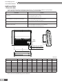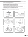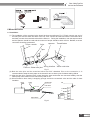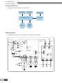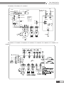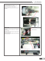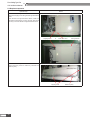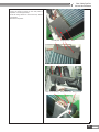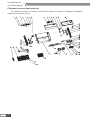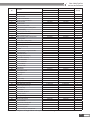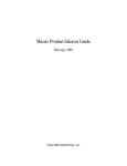
1
Floor Ceiling Type Fan Coil Unit Service Manual
( GC201409-I )
CONTENTS
PRODUCT������������������������������������������������������������������������������������������������������� 2
1 Models list ����������������������������������������������������������������������������������������������������������������� 2
2 Nomenclature of the unit������������������������������������������������������������������������������������������� 3
3 Function���������������������������������������������������������������������������������������������������������������������� 3
4 Specification��������������������������������������������������������������������������������������������������������������� 4
5 Working principle����������������������������������������������������������������������������������������������������� 10
CONTROL����������������������������������������������������������������������������������������������������� 12
1 Unit control��������������������������������������������������������������������������������������������������������������� 12
2 Wireless remote controller -Y512��������������������������������������������������������������������������� 13
3 Wireless remote controller -YB1FA������������������������������������������������������������������������ 16
INSTALLATION��������������������������������������������������������������������������������������������� 20
1 Dimension data ������������������������������������������������������������������������������������������������������� 20
2 Selection of installation location���������������������������������������������������������������������������� 22
3 There are 2 styles of installation���������������������������������������������������������������������������� 22
5 Drain piping work����������������������������������������������������������������������������������������������������� 24
6 Motorized valve�������������������������������������������������������������������������������������������������������� 25
7 Evakyation of the perfirmance�������������������������������������������������������������������������������� 26
8 Check after installation������������������������������������������������������������������������������������������� 27
MAINTENANCE�������������������������������������������������������������������������������������������� 29
1 Error code����������������������������������������������������������������������������������������������������������������� 29
2 Troubleshooting������������������������������������������������������������������������������������������������������� 29
3 Power distribution��������������������������������������������������������������������������������������������������� 30
4 Wiring diagram��������������������������������������������������������������������������������������������������������� 30
5 Disassembly of key spare part������������������������������������������������������������������������������� 32
6 Exploded view and spare parts list������������������������������������������������������������������������ 36
Floor Ceiling Type Fan
Coil Unit Service Manual
PRODUCT
1
PRODUCT
Floor Ceiling Type Fan
Coil Unit Service Manual
PRODUCT
1 Models list
Model Name
Product Code
Cooling/Heating
Capacity
(W)
FP-34WM-K
EM51700070
1800/2800
FP-51WM-K
EM51700080
2800/4150
FP-68WM-K
EM51700020
3600/5400
FP-85WM-K
EM51700050
4500/6800
FP-102 WM-K
EM51700060
5400/8100
FP-136WM-K
EM51700010
7200/10800
FP-170WM-K
EM51700040
8600/13500
FP-204WM-K
EM51700030
9700/16200
Model Name
Product Code
Cooling/Heating
Capacity
(W)
FP-34WM-D
EM51700090
2000/3510
FP-51WM-D
EM51700100
2800/4850
FP-68WM-D
EM51700110
4000/6500
FP-85WM-D
EM51700120
5170/8100
Power Supply
(V, Ph, Hz)
220-240V~ 50Hz
Power Supply
(V, Ph, Hz)
208-230V~ 60Hz
PRODUCT
2
FP-102WM-D
EM51700130
5680/9200
FP-136WM-D
EM51700140
7050/10600
FP-170WM-D
EM51700150
9000/14500
FP-204WM-D
EM51700160
9700/15900
Remarks
Remarks
Floor Ceiling Type Fan
Coil Unit Service Manual
Model Name
Product Code
Cooling/Heating
Capacity
(W)
FP-34ZD-K
EM56000100
2000/6700
FP-51ZD-K
EM56000110
2800/7600
FP-68ZD-K
EM56000130
3600/8500
FP-85ZD-K
EM56000120
4200/9500
Power Supply
(V, Ph, Hz)
Remarks
220-240V~ 50Hz
FP-102ZD-K
EM56000140
5400/12600
FP-136ZD-K
EM56000150
6350/13700
FP-170ZD-K
EM56000160
8900/19000
FP-204ZD-K
EM56000170
9900/21000
2 Nomenclature of the unit
FP
-
1
□
□
2
3
-
NO.
Description
1
Fan coil
2
Air flow volume
Number×10 m3/h
3
Installation Type
WM-Floor and ceiling type
ZD-Floor and ceiling type
4
Power supply
D
4
Options
Fan coil unit
K-220-240V~ 50Hz;D-208-230V~ 60Hz
FP-68WM-k:Floor ceiling fan coil unit with a nominal airflow volume of 680m3/h.
Note: face the air inlet of the unit, it is left type (“Z” for short) when the water in/outlet pipe is on the left
side of the unit, otherwise is right side, “Y” for short.
3 Function
Novel pattern: the exposed skin plates of unit look so elegant and luxurious that they can be taken as the
indoor decorations.
●● Low noise: Dynamic principles have been adopted for the design of the fan blades so as to make sure
the air volume is enough and running noise is considerably low.
●● Durable filter screen: The durable filter screen shares a cleaning cycle 20 times longer than that of the
conventional filter screen, needless to clean it frequently.
●● Microcomputer control: The unit is able to automatically adjust the fan speed in accordance with the
indoor ambient temperature to meet a wide range of users’ requirements.
●● Small height of the unit, saving much installation space.
●● Large cooling (heating) capacity, low noise, three-speed motor which can adjust the air volume and
meet a wide range of users’ requirements.
●● Excellent material, stringent process control, which guarantee the hi-quality and long life of the unit.
3
PRODUCT
Floor Ceiling Type Fan
Coil Unit Service Manual
4 Specification
Model
FP-34WM-K
FP-51WM-K
FP-68WM-K
FP-85WM-K
Code
EM51700070
EM51700080
EM51700020
EM51700050
CFM
High
Medium
Air flow volume
Low
300
400
500
m /h
340
510
680
850
CFM
146
232
291
375
3
m /h
248
395
495
638
CFM
125
155
194
250
3
m /h
213
264
330
425
W
1800
2800
3600
4500
Heating
W
2800
4150
5400
6800
Type
V-PhHz
220-240V~ 50Hz
220-240V~ 50Hz
220-240V~ 50Hz
220-240V~ 50Hz
Cooling
Capacity
200
3
Power system
Input
Exterior static pressure
Water flow
volume
Water system
Pressure drop
W
40
60
62
77
Pa
0
0
0
0
3
m /h
0.37
0.5
0.64
0.81
kPa
9.8
9.8
36.5
36.5
Aluminum fincopper tube
Aluminum fincopper tube
Aluminum fincopper tube
Aluminum fincopper tube
≤1.6MPa
≤1.6MPa
≤1.6MPa
≤1.6MPa
Type
Coil
Operating
pressure
MPa
Isolation B Capacitor Isolation B Capacitor Isolation B Capacitor Isolation B Capacitor
startup threestartup threestartup threestartup threespeed Motor
speed Motor
speed Motor
speed Motor
Type
Motor
Capacitor
μF
1.5
1.5
3
3
Sound
pressure level
dB(A)
48
48
49
49
inch
3/4(inner groove)
3/4(inner groove)
3/4(inner groove)
3/4(inner groove)
inch
3/4(outer groove)
3/4(outer groove)
3/4(outer groove)
3/4(outer groove)
mm
834×238×694
834×238×694
1300×188×600
1300×188×600
Package dimension (W × D × H)
mm
960×330×830
960×330×830
1414×248×724
1414×248×724
Net weight
kg
26
26
34
34
Sound pressure
level
Water inlet
&outlet
Condensing
water drain
Outline dimension (W × D × H)
Connection
pipe size
Gross weight
Loading quantity
kg
35
35
38
38
20'GP
112
112
108
108
40'GP
224
224
220
220
40'HQ
Wireless remote controller
PRODUCT
4
267
267
244
244
Y512
Y512
Y512
Y512
Floor Ceiling Type Fan
Coil Unit Service Manual
Model
Code
High
Air flow volume
Low
Capacity
FP-170WM-K
FP-204WM-K
EM51700060
EM51700010
EM51700040
EM51700030
600
800
1000
1200
3
1020
1360
1700
2040
CFM
464
644
750
926
m3/h
789
1095
1276
1575
CFM
309
429
500
618
3
m /h
525
730
850
1051
Cooling
W
5680
7050
8600
9700
Heating
W
9200
10600
13500
16200
Type
V-PhHz
220-240V~ 50Hz
220-240V~ 50Hz
220-240V~ 50Hz
220-240V~ 50Hz
Input
W
99
162
162
198
Pa
0
0
0
0
3
0.94
1.32
1.52
1.97
Power system
Exterior static pressure
Water flow
volume
Water system
Pressure drop
m /h
kPa
Type
Coil
FP-136WM-K
CFM
m /h
Medium
FP-102WM-K
Operating
pressure
MPa
34.8
38.4
42.8
Aluminum fincopper tube
Aluminum fincopper tube
Aluminum fincopper tube
≤1.6MPa
≤1.6MPa
≤1.6MPa
≤1.6MPa
Isolation B Capacitor Isolation B Capacitor Isolation B Capacitor Isolation B Capacitor
startup threestartup threestartup threestartup threespeed Motor
speed Motor
speed Motor
speed Motor
Type
Motor
30.8
Aluminum fincopper tube
Capacitor
μF
3
5
5
10
Sound pressure
level
dB(A)
49
51
52
55
inch
3/4(inner groove)
3/4(inner groove)
3/4(inner groove)
3/4(inner groove)
inch
3/4(outer groove)
3/4(outer groove)
3/4(outer groove)
3/4(outer groove)
mm
1300×188×600
1590×238×695
1590×238×695
1590×238×695
Package dimension (W × D × H)
mm
1414×248×724
1714×330×830
1714×330×830
1714×330×830
Net weight
kg
34
48.5
48.5
48.5
Gross weight
kg
38
57
57
57
20'GP
108
58
58
58
40'GP
220
111
111
111
40'HQ
244
117
117
117
Y512
Y512
Y512
Y512
Sound
pressure level
Water inlet
&outlet
Condensing
water drain
Outline dimension (W × D × H)
Connection
pipe size
Loading quantity
Wireless remote controller
5
PRODUCT
Floor Ceiling Type Fan
Coil Unit Service Manual
Model
Code
High
Air flow volume
Medium
Low
FP-68WM-D
FP-85WM-D
EM51700120
EM51700090
EM51700100
EM51700110
CFM
235
300
400
483
m3/h
400
510
680
820
CFM
172
232
291
362
m3/h
292
395
495
615
CFM
147
155
194
241
250
264
330
410
Cooling
W
2000
2800
4000
5170
Heating
W
3510
4850
6500
8100
Type
V-Ph-Hz
208-230V~ 60Hz
208-230V~ 60Hz
208-230V~ 60Hz
208-230V~ 60Hz
Input
W
47
49
69
81
Exterior static pressure
Pa
0
0
0
0
Water flow volume
m3/h
0.5
0.57
0.74
0.89
Pressure drop
kPa
Type
-
Operating pressure
MPa
10
Aluminum fincopper tube
≤1.6MPa
12
Aluminum fincopper tube
≤1.6MPa
18
Aluminum fincopper tube
≤1.6MPa
30
Aluminum fincopper tube
≤1.6MPa
Type
-
Isolation B
Capacitor startup
three-speed Motor
Capacitor
μF
1
1
1.5
2.5
Sound pressure
level
dB(A)
41
41
46
49
Water inlet &outlet
inch
3/4(inner groove)
3/4(inner groove)
3/4(inner groove)
3/4(inner groove)
Condensing
water drain
inch
3/4(outer groove)
3/4(outer groove)
3/4(outer groove)
3/4(outer groove)
Outline dimension (W × D × H)
mm
834×238×694
834×238×694
834×238×694
834×238×694
Package dimension (W × D × H)
mm
960×330×830
960×330×830
960×330×830
960×330×830
Net weight
kg
26
26
27
27
Gross weight
kg
33
33
34
34
20'GP
112
112
112
112
Power system
Water system
Coil
Motor
Sound
pressure level
Connection
pipe size
Loading quantity
Wireless remote controller
6
FP-51WM-D
m3/h
Capacity
PRODUCT
FP-34WM-D
Isolation B Capacitor Isolation B Capacitor Isolation B Capacitor
startup threestartup threestartup threespeed Motor
speed Motor
speed Motor
40'GP
224
224
224
224
40'HQ
267
267
267
267
YB1FA(XFAN)
YB1FA(XFAN)
YB1FA(XFAN)
YB1FA(XFAN)
Floor Ceiling Type Fan
Coil Unit Service Manual
Model
FP-102WM-D
FP-136WM-D
FP-170WM-D
FP-204WM-D
Code
EM51700130
EM51700140
EM51700150
EM51700160
CFM
600
700
1000
1200
3
m /h
1020
1190
1700
2040
CFM
450
525
750
926
3
m /h
765
892
1276
1575
CFM
300
350
500
618
3
m /h
510
595
850
1051
Cooling
W
5680
7050
9000
9700
Heating
W
9200
10600
14500
15900
Type
V-Ph-Hz
208-230V~ 60Hz
208-230V~ 60Hz
208-230V~ 60Hz
208-230V~ 60Hz
Input
W
99
103
165
215
Pa
0
0
0
0
Water flow volume
3
m /h
0.93
1.15
1.55
1.66
Pressure drop
kPa
50
55
55
55
Type
-
Aluminum fincopper tube
Aluminum fincopper tube
Aluminum fin-
Aluminum fin-
copper tube
copper tube
Operating pressure
MPa
≤1.6MPa
≤1.6MPa
≤1.6MPa
≤1.6MPa
Isolation B
Isolation B
High
Air flow volume
Medium
Low
Capacity
Power system
Exterior static pressure
Water system
Coil
Type
Motor
Sound pressure level
Connection pipe size
-
Isolation B
Isolation B
Capacitor startup Capacitor startup Capacitor startup
three-speed Motor three-speed Motor three-speed Motor
Capacitor startup
three-speed Motor
Capacitor
μF
3
3
5
6
Sound pressure level
dB(A)
51
51
48
50
Water inlet &outlet
inch
3/4(inner groove) 3/4(inner groove)
3/4(inner groove)
3/4(inner groove)
Condensing water drain
inch
3/4(outer groove) 3/4(outer groove)
3/4(outer groove)
3/4(outer groove)
Outline dimension (W × D × H)
mm
1300×188×600
1300×188×600
1590×238×695
1590×238×695
Package dimension (W × D × H)
mm
1414×248×724
1414×248×724
1714×330×830
1714×330×830
Net weight
kg
31.5
32.5
48.5
48.5
Gross weight
kg
36.5
37.5
57
57
20'GP
108
108
58
58
40'GP
220
220
111
111
40'HQ
244
244
117
117
YB1FA(XFAN)
YB1FA(XFAN)
YB1FA(XFAN)
YB1FA(XFAN)
Loading quantity
Wireless remote controller
Note:
The water working temperature is from 7ºC (44.6ºF) to 60ºC (140ºF).
The temperature exchange efficiency and enthalpy exchange efficiency are tested under these
testing conditions as below:
(1) Cooling efficiency: air 27ºC(80.6ºF) DB, 19.5ºC(67.1ºF) WB, water temperature in 7ºC(44.6ºF) water
out 12ºC(53.6ºF).
(2) Heating efficiency: air 21ºC (69.8ºF) DB, Water temperature: 60ºC (140ºF).
The operating water pressure of the models above is no more than 0.25MPa.
The airflow volume is tested when the ESP is 0 Pa.
7
PRODUCT
Floor Ceiling Type Fan
Coil Unit Service Manual
Model
FP-34ZD-K
FP-51ZD-K
FP-68ZD-K
FP-85ZD-K
Code
EM56000100
EM56000110
EM56000130
EM51700120
CFM
235
300
400
424
3
m /h
400
510
680
720
CFM
172
232
265
362
3
m /h
292
395
450
615
CFM
147
155
253
241
m3/h
250
264
430
410
Cooling
W
2000
2800
3600
4200
Heating
W
5000
7200
8500
9500
Type
V-PhHz
220-240V~ 50Hz
220-240V~ 50Hz
220-240V~ 50Hz
220-240V~ 50Hz
Input
W
36
58
72
80
High
Medium
Air flow volume
Low
Capacity
Power system
Exterior static pressure
Water system
Pa
0
0
0
0
Water flow
volume
L/s
0.125
0.14
0.16
0.20
Pressure drop
kPa
16.5
5
10
20
Aluminum fincopper tube
Aluminum fincopper tube
Aluminum fincopper tube
Aluminum fincopper tube
≤1.6MPa
≤1.6MPa
≤1.6MPa
≤1.6MPa
Type
Coil
Operating
pressure
Isolation B Capacitor Isolation B Capacitor Isolation B Capacitor Isolation B Capacitor
startup threestartup threestartup threestartup threespeed Motor
speed Motor
speed Motor
speed Motor
Type
Motor
Capacitor
μF
1
1
1.5
3.0
Sound pressure
level
Sound
pressure level
dB(A)
37
38
45
47
Connection
pipe size
Water inlet
&outlet
Condensing
water drain
inch
3/4(inner groove)
3/4(inner groove)
3/4(inner groove)
3/4(inner groove)
inch
3/4(inner groove)
3/4(inner groove)
3/4(inner groove)
3/4(inner groove)
Outline dimension (W × D × H)
mm
834×238×694
834×238×694
834×238×694
834×238×694
Package dimension (W × D × H)
mm
963×333×845
963×333×845
963×333×845
963×333×845
Net weight
kg
26
26
27
27
Gross weight
kg
33
33
34
34
20'GP
112
112
112
112
Loading quantity
Wireless remote controller
PRODUCT
MPa
8
40'GP
224
224
224
224
40'HQ
267
267
267
267
YB1FA(XFAN)
YB1FA(XFAN)
YB1FA(XFAN)
YB1FA(XFAN)
Floor Ceiling Type Fan
Coil Unit Service Manual
Model
FP-102ZD-K
FP-136ZD-K
FP-170ZD-K
FP-204ZD-K
Code
EM56000140
EM56000150
EM56000160
EM56000170
High
Air flow volume
Medium
Low
Capacity
CFM
600
647
1059
1201
m3/h
1020
1100
1800
2040
CFM
450
518
751
927
3
m /h
765
880
1276
1575
CFM
300
324
500
619
3
510
550
850
1051
m /h
Cooling
W
5400
6350
8900
9900
Heating
W
11500
13700
19000
21000
Type
V-PhHz
220-240V~ 50Hz
220-240V~ 50Hz
220-240V~ 50Hz
220-240V~ 50Hz
Input
W
86
78
150
200
Pa
0
0
0
0
L/s
0.27
0.32
0.40
0.44
kPa
36
38
52
55
Aluminum fincopper tube
Aluminum fincopper tube
Aluminum fincopper tube
Aluminum fincopper tube
≤1.6MPa
≤1.6MPa
≤1.6MPa
≤1.6MPa
Power system
Exterior static pressure
Water flow
volume
Water system
Pressure drop
Type
Coil
Operating
pressure
MPa
Isolation B Capacitor Isolation B Capacitor Isolation B Capacitor Isolation B Capacitor
startup threestartup threestartup threestartup threespeed Motor
speed Motor
speed Motor
speed Motor
Type
Motor
Capacitor
μF
3.0
3.0
5.0
10.0
Sound pressure
level
dB(A)
49
48
50
55
inch
3/4(inner groove)
3/4(inner groove)
3/4(inner groove)
3/4(inner groove)
inch
3/4(outer groove)
3/4(outer groove)
3/4(outer groove)
3/4(outer groove)
mm
1300×188×600
1300×188×600
1590×238×695
1590×238×695
Package dimension (W × D × H)
mm
1417×251×739
1417×251×739
1717×333×845
1717×333×845
Net weight
kg
31.5
32.5
48.5
48.5
Gross weight
kg
36.5
37.5
57
57
20'GP
108
108
58
58
40'GP
220
220
111
111
40'HQ
244
244
117
117
YB1FA(XFAN)
YB1FA(XFAN)
YB1FA(XFAN)
YB1FA(XFAN)
Sound
pressure level
Water inlet
&outlet
Condensing
water drain
Outline dimension (W × D × H)
Connection
pipe size
Loading quantity
Wireless remote controller
Note:
The water working temperature is from 7ºC (44.6ºF) to 60ºC (140ºF).
The temperature exchange efficiency and enthalpy exchange efficiency are tested under these testing
conditions as below:
(1) Cooling efficiency: air 27ºC(80.6ºF) DB, 19ºC(66.2ºF) WB, water temperature in 7ºC(44.6ºF) water out
12ºC(53.6ºF).
(2) Heating efficiency: air 20ºC (68ºF) DB, ater temperature in60ºC(140ºF) water out 70ºC(158ºF)
The operating water pressure of the models above is no more than 0.25MPa.
The airflow volume is tested when the ESP is 0 Pa.
9
PRODUCT
Floor Ceiling Type Fan
Coil Unit Service Manual
5 Working principle
The cool (hot) water go in the fan coil and make heat exchange with the indoor circulated air (outdoor air),
to realize cooling(heating), dehumidifying, filtrating or purifying. The processed air will be supplied to indoor
directly or by air duct.
Water Outlet Pipe
Water Inlet Pipe
Fan
Air Return
Filter Screen
PRODUCT
10
Air Supply
Floor Ceiling Type Fan
Coil Unit Service Manual
CONTROL
11
CONTROL
Floor Ceiling Type Fan
Coil Unit Service Manual
CONTROL
1 Unit control
1.1 Control logic
1) Independent control system, the logic is showed as below:
Mainboard
Display
Wireless remote
controller
1.2 AC control principle sketch
Following components could be controlled by the FCU: water pump (cassette type), water valve, fan, swing
fan (cassette, horizontal exposed, vertical exposed), auxiliary electric heater and water overflow protection
signal. The communication data between mainboard and display board is 485, the display board could be
controlled by wireless remote controller.
Note: concealed ceiling FCU is excluded in above information.
1.3 Unit operation control
CONTROL
12
Floor Ceiling Type Fan
Coil Unit Service Manual
2 Wireless remote controller -Y512
Notices:
♦♦ It is a universal wireless remote controller that is widely applicable for various kinds of AC.
♦♦ Make sure there’s no block between wireless remote controller and signal receiver.
♦♦ The signal receiving distance of wireless remote controller is 8m.
♦♦ Take care not to drop the wireless remote controller.
♦♦ Do not let any liquid flow into the wireless remote controller and avoid direct sunlight.
SWING button
FAN button
Press this button to
change the fan speed of:
When it is pressed,the louvers
start to totate automatically and
stop when repressed.
AUTO FAN
TEMP� button
SET TEMP. increases 1 °C by
pressing
button once,and
decreases 1°C by pressing
button once.
AT COOL mode operation,SET
TEMP.can be selected from16 °C
to 30 °C.
AT DRY mode operation, SET
TEMP. can be selected from 16°C
Under Auto mode operation,
standard SET TEMP.is 25°C for
COOL and 20°C for HEAT mode.
to 30 °C.
AT HEAT mode operation, SET
TEMP. can be selected from 16°C
to 30 °C.
Under Auto mode operation,
standard SET TEMP.is 25°C for
COOL and 20°C for HEAT mode.
“cool”mode
“DRY”mode
“FAN”mode
“HEAT”mode
ON/OFF button
Press this button to turn
on or turn off the unit.
MODE buttom
Press this button to change
the opearation mode in
order of:
AUTO
ON/OFF
Under Auto mode operation,
standard SET TEMP.is 25°C for
COOL and 20°C for HEAT mode.
13
CONTROL
Floor Ceiling Type Fan
Coil Unit Service Manual
2.1 Name and Function-Remote controller. (Remove the cover)
Note: This type of remote controller is a kind of new current controller. Some buttons of the controller
which are not available to this Air conditioner will not be described below. Operate are on unmentioned buttons
would not impact on the normal use.
Liquid crystal displayer. It
shows all set contents.
SLEEP button
Press this button to set SLEEP
operation, and stop when
repressed.
As the unit is cooling or dry,
if SLEEP operarion is set,
SET TEMP. would increase
1°C in 1 hour and 2 °C in 2
hours.
As the unit is heating, if
SLEEP operation is set,
SET TEMP. would decrease
in °C 1 hour and 2°C in 2
hours.
TIMER OFF button
At operating, TIMER
OFF button, set OFF
TIME in range of 0.5
to 24 hour to stop the
unit automatically.
0.5
ON/OFF
24h
Timer
cancellation
TIMER ON button
At stopping, oressTIMER ON button,
set ON TIME in range of 0.5to 24 hour
to stop the unit automatically.
0.5
24h
Timer
cancellation
CONTROL
14
Floor Ceiling Type Fan
Coil Unit Service Manual
2.2 How to insert batteries
●● Remove the cover from the back of the remote controller.
●● Insert two batteries ( TWO AAA dry-cell batteries ) and press button “ACL”.
●● Re-attach the cover.
NOTE:
♦♦ Don’t confuse the new and worn or different types of batteries.
♦♦ Remove batteries when the remote controller is not in use for a longtime.
♦♦ The lifetime of the batteries is about one year.
♦♦ The remote controller should be placed about 1 m or more away from the TV. Or any other electric
appliances.
♦♦ Bad batteries are forbidden.
15
CONTROL
Floor Ceiling Type Fan
Coil Unit Service Manual
3 Wireless remote controller -YB1FA
●● ON/OFF
Press ON/OFF button to turn on/off the unit. When the unit is turned off, the Timer, Sleep function will not
be retained in memory, but the time will be retained and is still displaying.
●● MODE
MODE button
Press this button, Auto, Cool, Dry, Fan Heat mode can be selected circularly.
Auto mode is not available in this mode.
●● SLEEP
SLEEP button
Press this button to select Sleep On/Sleep Off. If power is on, Sleep Off is default. If the unit is turned off,
the Sleep function setting will be not retained in memory. If Sleep function is on, the mark of Sleep will display.
In this mode, the time of timer can be adjusted. Under Fan and Auto modes, this function is not available.
●● FAN
FAN button
Press this button, Auto, Low, Medium, High-speed can be circularly selected. After powered on, Auto fan
speed is default. Under Dehumidify mode, Low fan speed is default.
AUTO
Low
Medium
High
Note: Under the Dry mode, the fan speed isn’t adjustable, low fan speed is default.
●● CLOCK
CLOCK button
Press Clock button to set the time of clock. When
blinks and displays, you can set the time by pressing
+ or - button. If no button is pressed within 10 seconds the remote will revert back to the normal display. Press
again to accept the setting. If it is set the first time, 12:00 is the initial value. Note: If mark
displays on the
LCD, it means it is the time of clock, if not, it is the time of timer.
●● LIGHT
LIGHT button
Press this button to select LIGHT On/Off in the displayer. When the LIGHT On is set,the mark will be
displayed and the indicator light in the displayer will be on. When the LIGHT Off is set, the mark will disappear
and the indicator light will be off.The function is not available for this mode.
CONTROL
16
Floor Ceiling Type Fan
Coil Unit Service Manual
●● X-FAN
X-FAN button
Press this button to turn on/off the X-FAN function.
The function is not available for this mode.
●● - button
Presetting temperature can be decrease the temperature by 1 degree Celsius once. press and hold for
more than two seconds so that we can change the temperature continuously. The minimum and maximum
setting range of the temperature is 16 to 30 degree Celsius.
●● + button
Press this button increase the temperature by 1 degree Celsius once. Press and hold for more than two
seconds so that we can change the temperature continuously. The minimum and maximum setting range of the
temperature is 16 to 30 degree.
●● TEMP
TEMP button
Press this button to select the display of either indoor setting temperature or indoor ambient temperature.
When the indoor unit powered on firstly, setting temperature display is default. Change status to
to display
the ambient temperature. If received control signal in 5 seconds, the display temp.will revert back to setting
temperature. When unit is off, indoor setting temperature display is default. Note: This function is only available
for certain models.
●● TURBO
TURBO button
In Cool or Heat mode, press this button to turn on/off the Turbo function.
●● SWING UP AND DOWN BUTTON
Press this button to adjust swing angle, which circularly changes as below:
OFF
This is a universal wireless remote controller; however, the unit covered in this manual is only of the
simplified SWING function. As a result, when the wireless remote controller is energized initially with the unit
under the OFF status, this simplified function should be set by pressing the + button and the SWING button
simultaneously, with the symbol blinking twice. Then, after the unit is turned on, this function can be activated
or deactivated simply by pressing the SWING button, with the displayed symbol indicating this function is on
and without this displayed symbol indicating this function is off.
●● TIMER ON BUTTON
Press the TIMER ON button to set the timed On. Press +/- once to increase or decrease the minute by 1
minute. If pressed and held for 2 seconds, the minute will increase or decrease constantly by 1 minute. If held
constantly for more than 5 seconds, the minute will begin to change in every 10 minutes. Press TIMER ON
again to accept the setting and ON will show besides the time of clock meaning the setting succeeds. Press the
TIMER ON again to cancel the setting.
●● TIMER OFF BUTTON
Press the TIMER OFF button to set the timed Off. The procedures are similar as above.
Note: This is a general remote control, it could be used for multiple types (functions) of air conditioners.
For some models without the functions specified here, we preserve the right to not to inform exclusively.
17
CONTROL
Floor Ceiling Type Fan
Coil Unit Service Manual
3.1 Operation of wireless remote control
3.1.1 Guide for operation – General operation
a.Press SLEEP button to set the sleep state.
b.Press TIME ON and TIME OFF button to scheduled the unit ON/OFF
c.Press LIGHT button to control on and off the indicator board.(This function
maybe not available for some units).
3.1.2 Guide for operation-Optional operation
a.After powered on, press ON/OFF button, the unit will start to run. (Note: When
it is powered off , the guide louver of main unit will close automatically.)
b.Press MODE button, select desired running mode ,or press COOL or HEAT
mode to enter the corresponding operation directly.
c.Press + or-button to set the desired temperature.
d.Press FAN button to set fan speed from AUTOFAN , LOW , MID and HIGH.
e.Press button to select SWING mode.
Press +and - buttons simultaneously to lock or unlock the wireless remote control.
If it is locked, the mark will display; when pressing any button, the mark
will blink
for three times but the air conditioner has no respondence. If unlocked, the mark will
disappear.
Switch between Fahrenheit and Centigrade.
When unit is under Off state, press MODE and – button simultaneously to switch
between ºF and ºC.
3.2 Changing batteries and notices.
a.Slightly to press the place with
, along the arrowhead direction to push
the back cover of wireless remote control. (As show in figure)
b.Take out the old batteries. (As show in figure)
c.Insert two new AAA1.5V dry batteries, and pay attention to the polarity. (As
show in figure).
d.Attach the back cover of wireless remote control. (As show in figure)
Fig.24
NOTE:
The design of this unit conforms to the requirements of ISO5151 standard.
The air volume is measured at the 0Pa external static pressure.
Fig.25
Cooling (heating) capacity stated above is measured under nominal working
Sketch map for
conditions corresponding to 0Pa external static pressure. The parameters are subject to
changing batteries
change with the improvement of products, in which case the values on the nameplate will prevail.
This product must not be disposed together with the domestic waste but disposed at the authorized place
for the recycling of electric and electronic appliances.
CONTROL
18
Floor Ceiling Type Fan
Coil Unit Service Manual
INSTALLATION
19
Floor Ceiling Type Fan
Coil Unit Service Manual
INSTALLATION
1 Dimension data
Check the following before contacting the service man. You may find the solution to your problem.
After checking, if it still doer not operate, please contact your local dealer.
PROBLEM
CAUSES
Check if electrical wire is damaged & check if breaker switch is still on.
Check if the power supply is in order.
Check if the timer switch is on or not.
The air conditioner runs but does not cool enough.
Check if the preset temperature is too high.
Check if the sunlight shines directly into the room.
Check if the door and window are opened.
Vapor or mist fume coming out of the unit while running.
Hot air in the room mixes with cool air. This causes smoke fume.
Inoperative remote control.
Loosened or disconnected wire between the unit and the display.
Check if the batteries are inserted in correct direction.
Check if the batteries are exhausted or not.
E
D
No operation.
F
(160)
4-16
Mounting Hole
B
G(water inlet pipe G3/4")
H(water outlet pipeG3/4")
A
C
Unit:mm
Model
FP-34WM-D
FP-34ZD-K
A
B
C
D
E
F
G
H
840
238
740
695
260
203
(130)
(215)
FP-51WM-D
FP-51ZD-K
840
238
740
695
260
203
(130)
(215)
FP-68WM-D
FP-68ZD-K
840
238
740
695
260
203
(130)
(215)
FP-85WM-D
FP-85ZD-K
840
238
740
695
260
203
(130)
(215)
FP-102WM-D
FP-102ZD-K
1300
188
1202
600
260
160
(106)
(172)
FP-136WM-D
FP-136ZD-K
1300
188
1202
600
260
160
(106)
(172)
FP-170WM-D
FP-170ZD-K
1590
238
1491
695
260
203
(97.5)
(178.5)
FP-204WM-D
FP-204ZD-K
1590
238
1491
695
260
203
(97.5)
(178.5)
Note: sizes in the brackets are just for reference.
20
E
D
Floor Ceiling Type Fan
Coil Unit Service Manual
Mounting Hole
B
A
C
Unit:mm
Model
A
B
C
D
E
FP-34WM-K
836
238
740
695
260
FP-51WM-K
836
238
740
695
260
FP-68WM-K
1300
188
1202
600
260
FP-85WM-K
1300
188
1202
600
260
FP-102WM-K
1300
188
1202
600
260
FP-136WM-K
1590
238
1491
695
260
FP-170WM-K
1590
238
1491
695
260
FP-204WM-K
1590
238
1490
695
260
21
Floor Ceiling Type Fan
Coil Unit Service Manual
2 Selection of installation location
etc.
(1) Such a place where cool air can be distributed throughout room.
(2) Such a place where condensation water is easily drained out
(3) Such a place that can handle the weight of the unit.
(4) Such a place which has easy access for maintenance.
(5) Such a place where is permitting easy connection with the chilling water pipe.
(6) Such a place where is 1m or more away from other electric appliances such as television, audio device,
(7) Avoid a location where there is heat source, high humidity or inflammable gas.
(8) Be sure that the installation conforms to the installation dimension diagram.
(9) The space around the unit is adequate for ventilation(Refer to Fig.2)
(10) The height of the installed location should be 2.3m or more from the floor.
150cm or more
INSTALLATION
PAPER PLANK
60cm or more
60cm or more
100cm or more
30cm or more
Fig.1
Fig.2
3 There are 2 styles of installation
(1) Ceiling Type
(2) Floor Type
Each type is similar to the other as follows;
1) Determine the mounting position on ceiling or wall.
2) Remove the return grill, the side panel, and suspender from the unit as per procedure below.
Press the fixing knob of the return grilles, the grilles will be opened wider and then pull it out from the unit.
(3) Remove the side panel fixing screw and pull to the front direction(arrow direction) to remove.(Refer to
Fig.3)
(4) Loosen two hanger bracket setting bolts(M8) on each side for less than 10mm. Remove two hanger
bracket fixing bolts(M6) on the rear side. Detach the hanger bracker by pulling backward (Refer to Fig.5)
Fig.3
(5) set the suspension bolt.(Use W3/8 or M10 size suspension bolts)
Adjust the distance from the unit to the ceiling slab beforehand (Refer to Fig.4)
22
Floor Ceiling Type Fan
Coil Unit Service Manual
(6) Fix the hanger bracket to the suspension bolt
Make sure that extended suspension bolt from the ceiling stays inside the arrowed position. Readjust the
hanger bracket when it is outside the arrowed position. (Refer to Fig.6)
Suspension bolt stays inside the cap of the init. Never remove the cap.
(7) Lift the unit and slide forward unit the dent.(Refer it Fig.7)
(8) Screw tightly both hanger bracket setting bolts(M8).(Refer to Fig.5)
(9) Screw tightly both hanger bracket fixing bolts (M6) to prevent the movement of the unit(Refer to Fig.5)
1) Adjust the unit height so that rear side of the drain pipe slightly inclines to improve drainage .
2) Adjust the height by turning the nut with a spanner.
3) Insert the spanner from the hanger bracket opening.(Refer to Fig.8)
♦♦ In case of hanging
It is possible to install using inward facing hanger brackets by not removing the brackets from the indoor
init.(Refer to.9)
Be sure to use only the specified accessories and parts for installation work.
Ceiling
Hanger bracket
Hanger b racket
setting bolt (M8)
Hanger bracket
Suspension bolt
Hanger bracket
Fig.4
Fig.5
Ceiling slab
Bolt position
inward
Hanger bracket
Fig.6
Fig.7
Fig.8
Fig.9
23
Floor Ceiling Type Fan
Coil Unit Service Manual
4 Electrical wiring
(1) Open the surface panel.
(2) Remove the electrical box cover.
(3) Route the power connection cord from the back of the indoor unit and pull it toward the front thought
the wiring hole for connection.
(4) Connect the wires of the power connection cord and valve connection cord as circuit diagram.
(5) Reassemble the electrical box cover.
(6) Recover the surface panel.
Power connection
cord and valve
connection cord
Wiring clamp
Rubber bush
Fig.11
Electrical box cover
Fig.12
5 Drain piping work
CAUTION:Make sure the drain flows out .
(1) Drain piping
1) The drain pipe outlet direction can be chosen from either the right rear or right.
2) The diameter of the drain pipe should be equal to or greater than the diameter of the connecting pipe.
(Vinyl tube; pipe size:20 mm; outer dimension:26 mm)
3) Keep the drain pipe short and incline downwards at a gradient of at least 111 00 to prevent air pockets.
(Refer to Fig.12)
4) Use the attached drain hose. ④ and clamp ⑤ .Insert the drain hose completely into the drain socket.
Tighten the clamp within the range of gray tape until the screw head is less than 4 mm from the hose.(Refer to
Fig.13,14)
5) Wrap the attached sealing pad OD over the clamp and drain hose to insulate. (Refer to Fig.14)
6) No folding of drain hose inside the unit. (Refer to Fig.15)
(2) Confirm that smooth drainage is achieved after the piping work.
Pour 600 cc of water into the drain pan from the air outlet for confirming drainage.(Refer to Fig.16)
24
Floor Ceiling Type Fan
Coil Unit Service Manual
6 Motorized valve
6.1 Installation
(1) The installation of the motorized valve should be done according as Fig.17.Firstly connect one end of
the tube joint with the water inlet tube of the unit, then connect the other end with the motorized valve,
and lastly connect the motorized valve with the flare nut . During the installation, both the torque wrench
and the spanner should be used and the moment of torque should be within 90 N.m. Besides, a secure
connection should be guaranteed.
Torque wrench
Spanner
Valve
Thread fasten
Tape
Wiring interface Water outlet tube
Flare nut Water tube joint
Fig.17
(2) Both the tube joint and the motorized valve are G3/4" threaded. Prior to the connection, it is
recommended to wrap the tacky tape on the thread for two or three cycles for better sealing effects
(3) After the tube joint, motorized valve, water inlet tube, water outlet tube are connected reliably, start the
water pump of the outdoor unit to check if they leak or not.
(4) What should be done lastly is wrapping sponge around the motorized valve and the tube for heat
insulation.
Body
Outlet tube
Valve
Power cord
PE
Inlet tube
PE
N
N
L
2
Water
Valve
Pipe sleeve
Fig.18
4
5
Terminal Board
25
Floor Ceiling Type Fan
Coil Unit Service Manual
6.2 Electric wiring
It is prohibited to bind directly the water valve wire and sponge
The right way is letting the water valve wire go through the pipe
up with the copper tube, as there would be probably a short circuit sleeve and then binding the sponge and pipe sleeve up(as Fig.20).
or even electric leakage(as Fig.19).
Water valve wire
Water valve wire
Water tube
Sponge
Water tube
PVC pipe sleeve
Sponge
Fig.19
Fig.20
It is prohibited to put the valve core upside down, as thiswould
allow the condensate water to enter or damage the valve core
and even form a short circuit which wouldresult in a fire hazard(as
Fig.21).
The right way is placing the valve core in the proper position
and letting the leading wire pointing at the unit(as Fig.22).
Fig.22
Fig.21
Sponge
It is prohibited to wrap the whole valve
with sponge, as this would affect the heat
diffusion of the valve core and probably pose
a fire hazard(as Fig.23).
Fig.23
7 Evakyation of the perfirmance
(1) Check electric main wire’s voltage.
(2) Use a thermometer to measure cool air both in and out.
(3) The difference between in-air and out-air temperature should not be less than 8℃
Thermometer
(4) The unit has Auto-restart function, it can remember the running model before power-broken.
(5) 26
Floor Ceiling Type Fan
Coil Unit Service Manual
8 Check after installation
Items to be checked
Possible malfunction
Has it been fixed firmly?
The unit may drop, shake or emit noise.
Is heat insulation sufficient?
It may cause condensation and dripping.
Does the insulation sufficient?
It may cause condensation and draping.
Situation
Is the voltage in accordance with the rated voltage
It may cause electric malfunction or damage the part.
marked on the nameplate?
Is the electrical wiring and piping connection installed
It may cause electric malfunction or damage the part.
correctly and securely?
Has the unit been connected to a secure earth
It may cause electrical leakage.
connection?
Is the power cord specified
It may cause eclectic malfunction or damage the part,
Has the inlet and outlet been covered?
It may cause insufficient cooling or heating capacity
27
Floor Ceiling Type Fan
Coil Unit Service Manual
MAINTENANCE
28
Floor Ceiling Type Fan
Coil Unit Service Manual
MAINTENANCE
1 Error code
Ambient temp. sensor malfunction
F0
Alarm error code display: F0
Surface-Cooer temp.
sensor malfunction
F1
Alarm error code display: F1
2 Troubleshooting
Unit can not work
If it is energized
NO
Energize the unit
YES
Replace actuator
NO
If the actuator
is energized
NO
YES
NO
Correctly connect
the wire
If the chiller is
turned on
NO If the wire connection
is correct
NO
NO
Turn on the chiller
YES
YES
Replace relay
or mainboard
If the water valve
is open
If the controller is
working normally
If the relay output
is normal
NO
If the wire
connection of mainboard
and transformer is correct
NO
Correctly connect
the wire
YES
YES
Correctly connect
the wire
NO
If the motor wire
connection is
correct
NO
If the fan is operate
normally
·
If the transformer
output is normal
YES
Replace motor
NO
If the motor
winding resistance
if normal
YES
Replace capacitor
NO
If the capacitor
is well
YES
Replace relay or
mainboard
NO
if the relay output
is normal
NO
Replace transformer
YES
Replace mainboard
YES
If the temperature
setting is
reasonable
NO
Reset the temperature
YES
If the mode set
is correct
NO
Adjust the operation mode
29
Floor Ceiling Type Fan
Coil Unit Service Manual
3 Power distribution
The logic in electric control box is as following:
Power supply
Transformer
Temp. sensor
Mainboard Control
Reveiver
Swing
Motor
Motor
4 Wiring diagram
FP-34WM-K; FP-51WM-K; FP-136WM-K; FP-170WM-K; FP-204WM-K.
Power
XT
L
N
4RD
WH
RD
9BU
PE
WATER
VALVE
10BU
X22
ROOM TEMP.
SENSOR
COMP
L
BN
R:20K
RT1
KM
X 19(LPP)
X 20(OVC)
X12
FUT:3.15A
250V~50T
X2
X3
X10
TUBE
X11
ROOM
CN1
X9
CN3
X8
X4
X2
X4
OROOM
EXHUST
X3
OTUBE
WH BK YE BU
RD
R:15K
BN
(RIGHT)
YEGN
PE
30
(LEFT)
R:10K
6BU
R:20K
7RD5
YE
Floor Ceiling Type Fan
Coil Unit Service Manual
FP-68WM-K; FP-85WM-K; FP-102WM-K.
Power
L
N
PE
4RD
N1 1BN
N 2WH
L2 3RD
9BU
WATER
VALVE
10BU
L
ROOM TEMP.
SENSOR
COMP
RT1
R:20K
X 19(LPP)
X 20(OVC)
FUT:3.15A
250V~50T
X12
X11
ROOM
X10
TUBE
CN1
CN3
X2
X3
X4
X3
OTUBE
WH BK YE BU
RD
R:20K
BN
(RIGHT)(
YEGN
LEFT)
5YE
E
FP-34WM-D; FP-51WM-D; FP-68WM-D; FP-85WM-D; FP-102WM-D; FP-136WM-D; FP-170WM-D; FP204WM-D.
31
Floor Ceiling Type Fan
Coil Unit Service Manual
FP-34ZD-K; FP-51ZD-K; FP-68ZD-K; FP-85ZD-K; FP-102ZD-K; FP-136ZD-K; FP-170ZD-K; FP-204ZD-K.
5 Disassembly of key spare part
5.1 replace motor
Operation step
Sketch
① .Open panel grille
Press the panel grille clamps.
Open the panel grille, squeeze the clamps to quit the
grille from clamp.
Clamp
32
Panel grille
Clamp
Floor Ceiling Type Fan
Coil Unit Service Manual
② .Remove propeller
Remove the propeller as 5.1 ① and 5.1
Remove rotate shaft sub-assy and shaft coupling
Loosen the fixing screws on shaft coupling.
Separate the shaft coupling and rotate shaft from the
motor shaft.
Fixing screw Shaft coupling
Rotate shaft sub-assy
Motor fixing screw
③ .Remove motor
Loosen the fixing screw on motor, to remove the motor
clamp assy.
Loosen the fixing screw on electric box, to remove the
electric box cover.
Remove the motor contact tag from wiring board and
capacitor of electric box.
Cut off the wiring harness, take out the motor wirings
and remove the motor.
Motor clamp assy
Tapping screw Electric box cover
Wiring harness
33
Floor Ceiling Type Fan
Coil Unit Service Manual
5.2 Replace evaporator
Operation step
Sketch
① .Remove left and right decorative board
Remove the tapping screw fixing left and right decorative
board.
Push the left and right decorative board, make the
decorative board clamps quit from the rear side board
sub-assy, to remove the left and right decorative board.
Tapping screw
E
lectric box cover
Wiring harness
② .Remove water tray
Loosen the fixing screw on water tray Remove the
water tray assy
Motor clamp assy
Tapping screw
34
Water tray assy
Floor Ceiling Type Fan
Coil Unit Service Manual
③ .Remove evaporator
Loosen the tapping screws on left side plate of
evaporator, cover and pipe clamp.
Cut off the wiring harness to remove the temp. sensor
on evaporator.
Remove the evaporator.
Left side plate T apping screw
Cover
tapping screw water pipe clamp
Temp. sensor bushing
Temp. sensor wire
Wiring harness
35
Floor Ceiling Type Fan
Coil Unit Service Manual
6 Exploded view and spare parts list
FP-34WM-K; FP-51WM-K; FP-34ZD-K; FP-51ZD-K;FP-34WM-D; FP-51WM-D; FP-68WM-D; FP-85WM-D
exploded view and spare part list.
36
Floor Ceiling Type Fan
Coil Unit Service Manual
No.
Discription
Name of Part
FP-34WM-K
FP-51WM-K
EM51700070
EM51700080
Product Code
Product Code
Quantity
1
Left Decoration Plate
261124152
261124152
2
Shaft of Louver
10512025
10512025
1
3
3
Guide Louver Bracket
24212019
24212019
2
4
Guide Louver Fixed Mount
24212018
24212018
1
5
Shaft of Louver
10512026
10512026
2
6
Guide Louver
1051953202
1051953202
1
7
Right Decoration Plate
261124162
261124162
1
8
Left Mounting Plate of Swing Motor
26152005
26152005
1
9
Panel Sub-assy
01532001
01532001
1
10
Mounting Box Sub-Assy
20102041
20102041
1
11
Display Board
30546104
30546104
1
12
Button Panel Sub-Assy
201620042
201620042
1
13
Right Mounting Plate of Swing Motor
26152006
26152006
1
14
Stepping Motor
15212402
15212402
2
15
Press Plate of Swing Motor
26112026
26112026
2
16
Water Tray Component
01279531
01279531
1
17
Pipe Hoop
70812001
70812001
1
18
Drain Pipe Sub-Assy
05235433
05235433
1
19
Handle
26232001
26232001
4
20
Foam Sub-assy of Right Side Plate
12312404
12312404
1
21
Mounting Plate
01332404
01332404
1
22
Decorative Board
26112027
26112027
1
23
Mounting Plate Sub-assy
01847502
01847502
1
24
Electric Box Sub-Assy
01403242
01403242
1
25
Press Wire Holder
24253001
24253001
1
26
Press Wire Board
24253002
24253002
1
27
Terminal Board
42010178
42010178
1
28
Protective Tube
46010013
46010013
1
29
Main Board
30036052
30036052
1
30
Transformer
43110237
43110237
1
31
Electric Box Cover
01413008
01413008
1
32
Centifugal Fan
10312401
10312401
2
33
Capacitor
33010020
33010020
1
34
Motor
15707302
15707302
1
35
Motor Clamp
70819522
70819522
4
36
Front propeller housing
22202031
22202031
2
37
Rear propeller housing
22202032
22202032
2
38
Rear Side Plate Sub-assy
0130201501
0130201501
1
39
Motor Support Sub-assy
01709532
01709532
1
40
Filter Sub-assy
11122013
11122013
1
41
Panel Grille
22412010
22412010
2
42
Panel Grille Buckle 2
26252003
26252003
4
43
Remote Control
305125033
305125033
1
44
Cooling coil assy
01109532
01109532
1
45
Panel Grille Buckle 1
26252002
26252002
4
46
Environment Sensor
39000186
39000186
1
47
Sensor Insert B
42020063
42020063
1
48
Cover Plate of Evaporator
01072409
01072409
1
49
Left Decorative Board
26112028
26112028
1
50
Left Mounting Plate
01332405
01332405
1
51
Foam Sub-assy of Left Side Plate
12312403
12312403
1
Above data is subject to change without notice,please refer the SP in global service website.
37
Floor Ceiling Type Fan
Coil Unit Service Manual
NO.
Discription
Name of Part
FP-34WM-D
FP-51WM-D
FP-68WM-D
FP-85WM-D
EM51700090
EM517000100
EM982300110
EM1447600120
Product Code
Product Code
Product Code
Product Code
Quantity
1
Left Decoration Plate
261124152
261124152
261124152
261124152
1
2
Shaft of Louver
10512025
10512025
10512025
10512025
3
3
Guide Louver Bracket
24212019
24212019
24212019
24212019
2
4
Guide Louver Fixed Mount
24212018
24212018
24212018
24212018
1
5
Shaft of Louver
10512026
10512026
10512026
10512026
2
6
Guide Louver
1051953202
1051953202
1051953202
1051953202
1
7
Right Decoration Plate
261124162
261124162
261124162
261124162
1
1
8
Left Mounting Plate of Swing Motor
26152005
26152005
26152005
26152005
9
Panel Sub-assy
01532001
01532001
01532001
01532001
1
10
Mounting Box Sub-Assy
201020413
201020413
201020413
201020413
1
11
Display Board
30295502
30295502
30295502
30295502
1
12
Button Panel Sub-Assy
201620041
201620041
201620041
201620041
1
13
Right Mounting Plate of Swing Motor
01326000052
01326000052
01326000052
01326000052
1
14
Stepping Motor
1521240211
1521240211
1521240211
1521240211
2
15
Press Plate of Swing Motor
26112026
26112026
26112026
26112026
2
16
Water Tray Component
01279531
01279531
01279531
01279531
1
17
Pipe Hoop
70812001
70812001
70812001
70812001
1
18
Drain Pipe Sub-Assy
05235433
05235433
05235433
05235433
1
19
Handle
26232001
26232001
26232001
26232001
4
20
Foam Sub-assy of Right Side Plate
12312404
12312404
12312404
12312404
1
21
Mounting Plate
01332404
01332404
01332404
01332404
1
22
Decorative Board
26112027
26112027
26112027
26112027
1
23
Mounting Plate Sub-assy
24
Electric Box Sub-Assy
01847502
01847502
01847502
01847502
1
01396000128
01396000128
01396000130
01396000131
1
25
Press Wire Holder
24253001
24253001
24253001
24253001
1
26
Press Wire Board
24253002
24253002
24253002
24253002
1
27
Terminal Board
42010268
42010268
42010268
42010268
1
28
Protective Tube
46010013
46010013
46010013
46010013
1
29
Main Board
30225056
30225056
30225056
30225056
1
30
Transformer
43110237
43110237
43110237
43110237
1
31
Electric Box Cover
01426000030
01426000030
01426000030
01426000030
1
32
Centifugal Fan
10312401
10312401
10312401
10312401
2
33
Capacitor
33010089
33010089
33010020
33010026
1
34
Motor
157073029
157073029
1570730210
1570730211
1
35
Motor Clamp
70819522
70819522
70819522
70819522
4
36
Front propeller housing
22202031
22202031
22202031
22202031
2
37
Rear propeller housing
22202032
22202032
22202032
22202032
2
38
Rear Side Plate Sub-assy
0130201501
0130201501
0130201501
0130201501
1
39
Motor Support Sub-assy
01709532
01709532
01709532
01709532
1
40
Filter Sub-assy
11122013
11122013
11122013
11122013
1
41
Panel Grille
22412010
22412010
22412010
22412010
2
42
Panel Grille Buckle 2
26252003
26252003
26252003
26252003
4
43
Remote Control
30510516
30510516
30510516
305125063
1
44
Cooling coil assy
01156000082
01126000067
01126000068
01126000069
1
45
Panel Grille Buckle 1
26252002
26252002
26252002
26252002
4
46
Environment Sensor
39000191
39000191
39000191
39000191
1
1
47
Sensor Insert B
42020063
42020063
42020063
42020063
48
Cover Plate Of Evaporator
01072409
01072409
01072409
01072409
1
49
Left Decorative Board
26112028
26112028
26112028
26112028
1
50
Left Mounting Plate
01332405
01332405
01332405
01332405
1
51
Foam Sub-assy of Left Side Plate
12312403
12312403
12312403
12312403
1
Above data is subject to change without notice,please refer the SP in global service website.
38
Floor Ceiling Type Fan
Coil Unit Service Manual
No.
Discription
Name of Part
FP-34ZD-K
FP-51ZD-K
EM56000100
EM56000110
Product Code
Product Code
Quantity
1
Left Decoration Board
26112028
26112028
1
2
Shaft of Louver
10512025
10512025
3
3
Guide Louver Bracket
24212096
24212096
2
4
Guide Louver Fixed Mount
24212018
24212018
1
5
Shaft of Louver
6
Guide Louver
10512026
10512026
2
1051953201
1051953201
7
1
Right Decoration Board
26112027
26112027
1
8
Left Mounting Plate of Swing Motor
26152005
26152005
1
9
Panel Sub-assy
01532001
01532001
1
10
Mounting Box Sub-Assy
201020415
201020415
1
11
Display Board
30295502
30295502
1
12
Button Panel Sub-Assy
201620041
201620041
1
13
Right Mounting Plate of Swing Motor
26152006
26152006
1
14
Stepping Motor
15212402
15212402
2
15
Press Plate of Swing Motor
26112026
26112026
2
16
Water Tray Component
01279531
01279531
1
17
Pipe Hoop
70812001
70812001
1
18
Drain Pipe Sub-Assy
2690320401
05235433
1
19
Handle
26232001
26232001
4
20
Foam Sub-assy of Right Side Plate
12312404
12312404
1
21
Mounting Plate
01332404
01332404
1
22
Decorative Board
26112027
26112027
1
23
Mounting Plate Sub-assy
01847502
01847502
1
24
Electric Box Sub-Assy
01396000128
01396000128
1
25
Press Wire Holder
24253001
24253001
1
26
Press Wire Board
24253002
24253002
1
27
Terminal Board
42010268
42010268
1
28
Protective Tube
/
/
1
29
Main Board
30225056
30225056
1
30
Transformer
43110237
43110237
1
31
Electric Box Cover
01426000030
01426000030
1
32
Centifugal Fan
10312401
10312401
2
33
Capacitor
33010089
33010089
1
34
Motor
157073029
157073029
1
35
Motor Clamp
70819522
70819522
4
36
Front propeller housing
22202031
22202031
2
37
Rear propeller housing
22202032
22202032
2
38
Rear Side Plate Sub-assy
01316000107
01316000107
1
39
Motor Support Sub-assy
01709532
01709532
1
40
Filter Sub-assy
11122013
11122013
1
41
Panel Grille
22412010
22412010
2
42
Panel Grille Buckle 2
26252003
26252003
4
43
Remote Control
30510516
30510516
1
44
Cooling coil assy
01126000066
01126000066
1
45
Panel Grille Buckle 1
26252002
26252002
4
46
Environment Sensor
39000286
39000286
1
47
Sensor Insert B
42020063
42020063
1
48
Cover Plate of Evaporator
01072409
01072409
1
49
Left Decorative Board
26112028
26112028
1
50
Left Mounting Plate
01332405
01332405
1
51
Foam Sub-assy of Left Side Plate
12312403
12312403
1
Above data is subject to change without notice,please refer the SP in global service website.
39
Floor Ceiling Type Fan
Coil Unit Service Manual
FP-68WM-K; FP-85WM-K; FP-102WM-K; FP-68ZD-K; FP-85ZD-K; FP-102ZD-K; FP-102WM-D; FP170WM-D; FP-136WM-D exploded view and spare parts list.
40
Floor Ceiling Type Fan
Coil Unit Service Manual
No.
1
FP-68WM-K
FP-85WM-K
FP-102WM-K
EM51700020
EM51700050
EM51700060
Name of Part
Part Code
Part Code
Part Code
Left Decoration Plate
261124172
261124172
261124172
Discription
2
Shaft of Louver
3
Guide Louver Bracket
Quantity
1
10512025
10512025
10512025
2
2690601702
2690601702
2690601702
3
4
Guide Louver Fixed Mount
24222016
24222016
24222016
2
5
Shaft of Louver
10512026
10512026
10512026
2
6
Guide Louver
105124042
105124042
105124042
1
7
Right Decoration Plate
261124212
261124212
261124212
1
8
Left Mounting Plate of Swing Motor
26152007
26152007
26152007
1
9
Panel Sub-assy
01532414
01532414
01532414
1
10
Mounting Box Sub-Assy
201020411
201020411
201020411
1
11
Display Board
30546106
30546106
30546106
1
12
Button Panel Sub-Assy
201620041
201620041
201620041
1
13
Right Mounting Plate of Swing Motor
26152008
26152008
26152008
1
14
Stepping Motor
15212402
15212402
15212402
2
15
Press Plate of Swing Motor
16
Water Tray Component
17
Pipe Hoop
26112026
26112026
26112026
2
0127241402
0127241402
0127241402
1
70812001
70812001
70812001
1
18
Drain Pipe Sub-Assy
05235433
05235433
05235433
1
19
Handle
26232001
26232001
26232001
4
20
Foam Sub-assy of Right Side Plate
12312407
12312407
12312407
1
21
Mounting Plate
01332404
01332404
01332404
1
22
Decorative Board
26112033
26112033
26112033
1
23
Mounting Plate Sub-assy
01847503
01847503
01847503
1
24
Electric Box Sub-Assy
01403242
01403242
01403242
1
25
Press Wire Holder
24253001
24253001
24253001
1
26
Press Wire Board
24253002
24253002
24253002
1
27
Terminal Board
42010178
42010178
42010178
1
28
Protective Tube
46010013
46010013
46010013
1
29
Main Board
30036052
30036052
30036052
1
30
Transformer
43110237
43110237
43110237
1
31
Electric Box Cover
01413008
01413008
01413008
1
32
Centifugal Fan
10312401
10312401
10312401
4
33
Capacitor
33010027
33010027
33010027
1
34
Motor
15012406
15012406
15012406
1
35
Axletree
73012403
73012403
73012403
2
36
Front propeller housing
22202031
22202031
22202031
4
37
Rear propeller housing
22202032
22202032
22202032
4
38
Rear Side Plate Sub-assy
01302418
01302418
01302418
1
39
Motor Support Sub-assy
01702401
01702401
01702401
1
40
Filter Sub-assy
11122012
11122012
11122012
1
41
Panel Grille
22412011
22412011
22412011
1
42
Panel Grille Buckle 2
26252003
26252003
26252003
2
43
Remote Control
305125063
305125063
305125063
1
44
Cooling coil assy
0112612001
0112612001
0112612001
1
45
Panel Grille Buckle 1
26252002
26252002
26252002
2
46
Environment Sensor
39000186
39000186
39000186
1
47
Water-leading board assy
1362401
1362401
1362401
1
48
Cover Plate Of Evaporator
01072417
01072417
01072417
1
49
Left Decorative Board
26112032
26112032
26112032
1
50
Left Mounting Plate
01332405
01332405
01332405
1
51
Foam Sub-assy of Left Side Plate
12312406
12312406
12312406
1
Above data is subject to change without notice,please refer the SP in global service website.
41
Floor Ceiling Type Fan
Coil Unit Service Manual
FP-102WM-D
FP-136WM-D
EM51700130
EM51700140
Name of Part
Part Code
Part Code
1
Left Decoration Plate
261124172
261124172
1
2
Shaft of Louver
10512025
10512025
2
3
Guide Louver Bracket
2690601702
2690601702
3
4
Guide Louver Fixed Mount
24222016
24222016
2
5
Shaft of Louver
10512026
10512026
2
6
Guide Louver
105124042
105124042
1
7
Right Decoration Plate
261124212
261124212
1
8
Left Mounting Plate of Swing Motor
26152007
26152007
1
9
Panel Sub-assy
01532414
01532414
1
10
Mounting Box Sub-Assy
01326000053
01326000053
1
No.
Discription
11
Display Board
30295502
30295502
1
12
Button Panel Sub-Assy
201620041
201620041
1
13
Right Mounting Plate of Swing Motor
26152008
26152008
1
14
Stepping Motor
1521240211
1521240211
2
15
Press Plate of Swing Motor
26112026
26112026
2
16
Water Tray Component
0127241402
0127241402
1
17
Pipe Hoop
70812001
70812001
1
18
Drain Pipe Sub-Assy
05235433
05235433
1
19
Handle
26232001
26232001
4
20
Foam Sub-assy of Right Side Plate
12312407
12312407
1
21
Mounting Plate
01332404
01332404
1
22
Decorative Board
26112033
26112033
1
23
Mounting Plate Sub-assy
01847503
01847503
1
24
Electric Box Sub-Assy
01396000132
01396000139
1
25
Press Wire Holder
24253001
24253001
1
26
Press Wire Board
24253002
24253002
1
27
Terminal Board
42010268
42010268
1
28
Protective Tube
46010013
46010013
1
29
Main Board
30225056
30225056
1
30
Transformer
43110237
43110237
1
31
Electric Box Cover
1426000030
1426000030
1
32
Centifugal Fan
10312401
10312401
4
33
Capacitor
33010027
33010027
1
34
Motor
15012406
15012406
1
35
Axletree
73012403
73012403
2
36
Front propeller housing
22202031
22202031
4
37
Rear propeller housing
22202032
22202032
4
38
Rear Side Plate Sub-assy
01302418
01302418
1
39
Motor Support Sub-assy
01702401
01702401
1
40
Filter Sub-assy
11122012
11122012
1
41
Panel Grille
22412011
22412011
1
42
Panel Grille Buckle 2
26252003
26252003
2
43
Remote Control
30510516
30510516
1
44
Cooling coil assy
01126000070
01126000072
1
45
Panel Grille Buckle 1
26252002
26252002
2
46
Environment Sensor
3900012123
3900012123
1
47
Water-leading board assy
1362401
1362401
1
48
Cover Plate Of Evaporator
01072417
01072417
1
49
Left Decorative Board
26112032
26112032
1
50
Left Mounting Plate
01332405
01332405
1
51
Foam Sub-assy of Left Side Plate
12312406
12312406
1
Above data is subject to change without notice,please refer the SP in global service website.
42
Quantity
Floor Ceiling Type Fan
Coil Unit Service Manual
No.
Discription
Name of Part
FP-68ZD-K
FP-85ZD-K
FP-102ZD-K
EM56000130
EM56000120
EM56000140
Part Code
Part Code
Part Code
Quantity
1
Left Decoration Plate
26112028
26112028
26112032
1
2
Shaft of Louver
10512025
10512025
10512025
2
3
Guide Louver Bracket
24212096
24212096
2690601701
3
4
Guide Louver Fixed Mount
24222016
24222016
24222016
2
5
Shaft of Louver
10512026
10512026
10512026
2
1051953201
1051953201
105124041
1
26112027
26112027
26112033
1
1
6
Guide Louver
7
Right Decoration Plate
8
Left Mounting Plate of Swing Motor
26152005
26152005
26152407
9
Panel Sub-assy
01532001P
01532001P
01532414
1
10
Mounting Box Sub-Assy
201020415
201020415
01326000053
1
11
Display Board
30295502
30295502
30295502
1
12
Button Panel Sub-Assy
201620041
201620041
201620041
1
13
Right Mounting Plate of Swing Motor
26152008
26152008
26152008
1
14
Stepping Motor
15212402
15212402
15212402
2
15
Press Plate of Swing Motor
26112026
26112026
26112026
2
16
Water Tray Component
01279531
01279531
0127241401
1
17
Pipe Hoop
18
Drain Pipe Sub-Assy
70812001
70812001
70812001
1
2690320401
2690320401
2690320401
1
19
Handle
26232001
26232001
26232001
4
20
Foam Sub-assy of Right Side Plate
12312404
12312404
12312407
1
21
Mounting Plate
01332404
01332404
01332404
1
22
Decorative Board
01332404
01332404
01332404
1
23
Mounting Plate Sub-assy
26112033
26112033
26112033
1
24
Electric Box Sub-Assy
01396000130
01396000500
01396000132
1
25
Press Wire Holder
24253001
24253001
24253001
1
26
Press Wire Board
24253002
24253002
24253002
1
27
Terminal Board
42010268
42010268
42010268
1
28
Protective Tube
46010013
46010013
46010013
1
29
Main Board
30225056
30225056
30225056
1
30
Transformer
43110237
43110237
43110237
1
31
Electric Box Cover
01426000030
01426000030
01426000030
1
32
Centifugal Fan
10312401
10312401
10312401
4
33
Capacitor
33010020
33010027
33010027
1
1570730210
1570730211
1501240602
1
73012403
73012403
73012403
2
34
Motor
35
Axletree
36
Front propeller housing
22202031
22202031
22202031
4
37
Rear propeller housing
22202032
22202032
22202032
4
38
Rear Side Plate Sub-assy
01319534
01319534
01302419
1
39
Motor Support Sub-assy
01709532
01709532
01702410
1
40
Filter Sub-assy
11122013
11122013
11122012
1
41
Panel Grille
22412010
22412010
22412011
1
42
Panel Grille Buckle 2
26252003
26252003
26252003
2
43
Remote Control
30510516
30510516
30510516
1
44
Cooling coil assy
01126000068
01126000069
01126000070
1
45
Panel Grille Buckle 1
26252002
26252002
26252002
2
46
Environment Sensor
39000286
39000286
39000286
1
47
Water-leading board assy
02227348P
02227348P
01362401
1
48
Cover Plate Of Evaporator
01072409
01072409
01072417
1
49
Left Decorative Board
26112028
26112028
26112032
1
50
Left Mounting Plate
01332405
01332405
01332405
1
51
Foam Sub-assy of Left Side Plate
12312403
12312403
12312406
1
Above data is subject to change without notice,please refer the SP in global service website.
43
Floor Ceiling Type Fan
Coil Unit Service Manual
FP-136WM-K; FP-170WM-K; FP-204WM-K; FP-136ZD-K; FP-170ZD-K; FP-204ZD-K;FP-170WM-D; FP204WM-D exploded view and spare parts list.
44
Floor Ceiling Type Fan
Coil Unit Service Manual
No.
FP-136WM-K
FP-170WM-K
FP-204WM-K
EM51700010
EM51700040
EM51700030
Name of Part
Part Code
Part Code
Part Code
Discription
Quantity
1
Left Decoration Plate
261124152
261124152
261124152
1
2
Shaft of Louver
10512025
10512025
10512025
3
3
Guide Louver Bracket
2421209601
2421209601
2421209601
4
4
Guide Louver Fixed Mount
24212018
24212018
24212018
3
5
Shaft of Louver
10512026
10512026
10512026
2
6
Guide Louver
105124082
105124082
105124082
1
7
Right Decoration Plate
261124162
261124162
261124162
1
8
Left Mounting Plate of Swing Motor
26152005
26152005
26152005
1
9
Panel Sub-assy
01532413
01532413
01532413
1
10
Mounting Box Sub-Assy
201020413
201020413
201020413
1
1
11
Display Board
30546104
30546104
30546104
12
Button Panel Sub-Assy
201620041
201620041
201620041
1
13
Right Mounting Plate of Swing Motor
26152006
26152006
26152006
1
14
Stepping Motor
15212402
15212402
15212402
2
15
Press Plate of Swing Motor
26112026
26112026
26112026
2
0127240802
0127240802
0127240802
1
70812001
70812001
70812001
1
16
Water Tray Component
17
Pipe Hoop
18
Drain Pipe Sub-Assy
05235433
05235433
05235433
1
19
Handle
26232001
26232001
26232001
4
20
Foam Sub-assy of Right Side Plate
12312404
12312404
12312404
1
21
Mounting Plate
01332404
01332404
01332404
1
22
Decorative Board
26112027
26112027
26112027
1
23
Mounting Plate Sub-assy
01847502
01847502
01847502
1
24
Electric Box Sub-Assy
01403242
01403242
01403242
1
25
Press Wire Holder
24253001
24253001
24253001
1
26
Press Wire Board
24253002
24253002
24253002
1
27
Terminal Board
42010178
42010178
42010178
1
28
Protective Tube
46010013
46010013
46010013
1
29
Main Board
30036052
30036052
30036052
1
30
Transformer
43110237
43110237
43110237
1
31
Electric Box Cover
01413008
01413008
01413008
1
32
Centifugal Fan
10319051
10319051
10319051
4
33
Capacitor
33010064
33010064
33010056
1
34
Motor
15012405
15012405
15012404
1
35
Axletree
73012403
73012403
73012403
2
36
Front propeller housing
22202030
22202030
22202030
4
37
Rear propeller housing
22202029
22202029
22202029
4
38
Rear Side Plate Sub-assy
1302412
1302412
1302412
1
39
Motor Support Sub-assy
01702406
01702406
01702406
1
40
Filter Sub-assy
11122013
11122013
11122013
1
41
Panel Grille
22412010
22412010
22412010
1
42
Panel Grille Buckle 2
26252003
26252003
26252003
2
43
Remote Control
305125063
305125063
305125063
1
44
Cooling coil assy
01126121
0112612101
0112612101
1
45
Panel Grille Buckle 1
26252002
26252002
26252002
2
46
Environment Sensor
39000186
39000186
39000186
1
47
Sensor Insert B
42020063
42020063
42020063
1
48
Cover Plate Of Evaporator
01072409
01072409
01072409
1
49
Left Decorative Board
26112028
26112028
26112028
1
50
Left Mounting Plate
01332405
01332405
01332405
1
51
Foam Sub-assy of Left Side Plate
12312403
12312403
12312403
1
Above data is subject to change without notice,please refer the SP in global service website.
45
Floor Ceiling Type Fan
Coil Unit Service Manual
No.
Discription
FP-170WM-D
FP-204WM-D
EM51700150
EM51700160
Name of Part
Part Code
Part Code
1
Left Decoration Plate
261124152
261124152
1
2
Shaft of Louver
10512025
10512025
3
3
Guide Louver Bracket
2421209601
2421209601
4
4
Guide Louver Fixed Mount
24212018
24212018
3
5
Shaft of Louver
10512026
10512026
2
6
Guide Louver
105124082
105124082
1
7
Right Decoration Plate
261124162
261124162
1
8
Left Mounting Plate of Swing Motor
26152005
26152005
1
9
Panel Sub-assy
01532413
01532413
1
10
Mounting Box Sub-Assy
201020413
201020413
1
11
Display Board
30295502
30295502
1
12
Button Panel Sub-Assy
201620041
201620041
1
13
Right Mounting Plate of Swing Motor
26152006
26152006
1
14
Stepping Motor
1521240211
1521240211
2
15
Press Plate of Swing Motor
26112026
26112026
2
16
Water Tray Component
0127240802
0127240802
1
17
Pipe Hoop
70812001
70812001
1
18
Drain Pipe Sub-Assy
05235433
05235433
1
19
Handle
26232001
26232001
4
20
Foam Sub-assy of Right Side Plate
12312404
12312404
1
21
Mounting Plate
01332404
01332404
1
22
Decorative Board
26112027
26112027
1
23
Mounting Plate Sub-assy
01847502
01847502
1
24
Electric Box Sub-Assy
01396000138
01396000137
1
25
Press Wire Holder
24253001
24253001
1
26
Press Wire Board
24253002
24253002
1
27
Terminal Board
42010268
42010268
1
28
Protective Tube
46010013
46010013
1
29
Main Board
30225056
30225056
1
30
Transformer
43110237
43110237
1
31
Electric Box Cover
01426000030
01426000030
1
32
Centifugal Fan
10319051
10319051
4
33
Capacitor
33010064
33010056
1
34
Motor
1501240501
1501240402
1
35
Axletree
73012403
73012403
2
36
Front propeller housing
22202030
22202030
4
37
Rear propeller housing
22202029
22202029
4
38
Rear Side Plate Sub-assy
1302412
1302412
1
39
Motor Support Sub-assy
01702406
01702406
1
40
Filter Sub-assy
11122013
11122013
1
41
Panel Grille
22412010
22412010
1
42
Panel Grille Buckle 2
26252003
26252003
2
43
Remote Control
30510516
30510516
1
44
Cooling coil assy
01126000071
01126000071
1
45
Panel Grille Buckle 1
26252002
26252002
2
46
Environment Sensor
3900012123
3900012123
1
47
Sensor Insert B
42020063
42020063
1
48
Cover Plate Of Evaporator
01072409
01072409
1
49
Left Decorative Board
26112028
26112028
1
50
Left Mounting Plate
01332405
01332405
1
51
Foam Sub-assy of Left Side Plate
12312403
12312403
1
Above data is subject to change without notice,please refer the SP in global service website.
46
Quantity
Floor Ceiling Type Fan
Coil Unit Service Manual
No.
Discription
Name of Part
FP-136ZD-K
FP-170ZD-K
FP-204ZD-K
EM56000150
EM56000160
EM56000170
Part Code
Part Code
Part Code
Quantity
1
Left Decoration Plate
26112032
26112028
26112028
1
2
Shaft of Louver
10512025
10512025
10512025
3
3
Guide Louver Bracket
2690601701
24212096
24212096
4
4
Guide Louver Fixed Mount
24222016
24212018
24212018
3
5
Shaft of Louver
10512026
10512026
10512026
2
6
Guide Louver
105124041
105124081
105124081
1
7
Right Decoration Plate
26112033
26112027
26112027
1
8
Left Mounting Plate of Swing Motor
26152007
26152005
26152005
1
9
Panel Sub-assy
01532414
01532413
01532413
1
10
Mounting Box Sub-Assy
01326000053
01326000053
01326000053
1
11
Display Board
30295502
30295502
30295502
1
12
Button Panel Sub-Assy
201620041
201620041
201620041
1
13
Right Mounting Plate of Swing Motor
26152008
26152006
26152006
1
14
Stepping Motor
15212402
15212402
15212402
2
15
Press Plate of Swing Motor
16
Water Tray Component
17
Pipe Hoop
18
Drain Pipe Sub-Assy
26112026
26112026
26112026
2
0127241401
0128940602
0128940602
1
70812001
70812001
70812001
1
2690320401
2690320401
2690320401
1
19
Handle
26232001
26232001
26232001
4
20
Foam Sub-assy of Right Side Plate
12312404
12312404
12312404
1
21
Mounting Plate
01332404
01332404
01332404
1
22
Decorative Board
26112027
26112027
26112027
1
23
Mounting Plate Sub-assy
01847503
01847502
01847502
1
24
Electric Box Sub-Assy
01396000132
01396000138
01396000452
1
25
Press Wire Holder
24253001
24253001
24253001
1
26
Press Wire Board
24253002
24253002
24253002
1
27
Terminal Board
42010268
42010268
42010268
1
28
Protective Tube
46010013
46010013
46010013
1
29
Main Board
30225056
30225056
30225056
1
30
Transformer
43110237
43110237
43110237
1
31
Electric Box Cover
01426000030
01426000030
01426000030
1
32
Centifugal Fan
10312401
10319051
10319051
4
33
Capacitor
33010027
33010027
33010056
1
1501240602
1501240501
1501240402
1
73012403
73012403
73012403
2
34
Motor
35
Axletree
36
Front propeller housing
22202031
22202030
22202030
4
37
Rear propeller housing
22202032
22202029
22202029
4
38
Rear Side Plate Sub-assy
01302419
01302411
01302411
1
39
Motor Support Sub-assy
01702410
01702411
01702406
1
40
Filter Sub-assy
11122012
11122012
11122013
1
41
Panel Grille
22412011
22412010
22412010
1
42
Panel Grille Buckle 2
26252003
26252003
26252003
2
43
Remote Control
30510516
30510516
30510516
1
44
Cooling coil assy
01126000072
01126000227
01126000227
1
45
Panel Grille Buckle 1
26252002
26252002
26252002
2
46
Environment Sensor
39000286
39000286
39000286
1
47
Sensor Insert B
42020063
42020063
42020063
1
48
Cover Plate Of Evaporator
01072417
01072409
01072409
1
49
Left Decorative Board
26112032
26112028
26112028
1
50
Left Mounting Plate
01332405
01332405
01332405
1
51
Foam Sub-assy of Left Side Plate
12312406
12312403
12312403
1
Above data is subject to change without notice,please refer the SP in global service website.
47
JF00301348