1
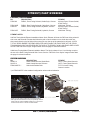
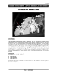
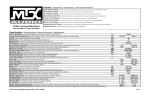
INSTALLATION INSTRUCTIONS Overview In our plight for Drivetrain perfection, we have come out with another innovation to make the riding experience on your American motorcycle, the pleasure it should be. We are proud to announce the re lease of the BAKER Reverse Kit, F6R for short.The BAKER Reverse system is unlike any other on the market in that it works off the stock foot shifter lever. With the simple hit of the Reverse Safety Toggle Switch, and a flick of your foot, you are in Reverse. It is that simple. No reaching near hot pipes to put a bike in Reverse anymore. The BAKER Reverse system is designed so that it is impossible to get a bike locked in 1st and Reverse, like on some other models out there. Additionally the Reverse Gears are all fully heat treated, diamond ground, gear grade 8620 steel. The BAKER Reverse shift drum also improves greatly over the ability to find neutral than stock. With an overall 4.98:1 gear ratio in Reverse, 45% shorter than the stock 3.34:1 first gear, it is essentially a creeper gear. V12-050713 f i tm e nt / pa rt numb ers FITMENT/ PART NUMBERS PN DESCRIPTIONFITMENT F6RV-MC F6R Kit, Front Facing Solenoid, Cable Style, Chrome 06-Later Dyna, 07-Later Softail, 07-08 Touring F6RV-MCR F6R Kit, Rear Facing Solenoid, Cable Style, Chrome 2009-Later Touring* F6RV-HC F6R Kit, Front Facing Solenoid, Hydraulic, Chrome 06-Later Dyna, 07-Later Softail, 07-08 Touring F6RV-HCR F6R Kit, Rear Facing Solenoid, Hydraulic, Chrome 2009-Later Touring* Fitment Notes: 2007-08 Touring Model Exhaust Installation Notes: Stock Exhaust will clear the F6R front facing solenoid side cover and solenoid. Exhaust that follows the path of stock exhaust or true duals where the rear pipe travels directly to the left side of the motorcycle over the top of the transmission will work. 2 INTO 1 STYLE PIPES WHERE THE REAR HEAD PIPE GOES DOWN THE FRONT SIDE OF THE STOCK TRANSMISSION SIDE COVER REQUIRE THE USE OF THE REAR FACING SOLENOID SIDE COVER. See the ‘F6R Side Cover Styles’ images further down the page for solenoid locations. 2009-Later Touring Model Exhaust Installation Notes: The Stock exhaust 2 into 1 into 2 design requires the use of the Rear Facing Solenoid Side Covers. See the ‘F6R Side Cover Styles’ images further down the page for solenoid locations SWITCH HOUSINGS PN DESCRIPTIONFITMENT SHB07-A Hand Control Mounted, Satin Black H-D™ Factory Hand Controls SHC07-A Hand Control Mounted, Chrome H-D™ Factory Hand Controls FRNG-MNT07** Switch with Rubber Boot FLT/ FLH Inner Fairing, Custom Location **pn FRNG-MNT07 is the standard configuration unless ordered otherwise. Shown is a 2011 Electra Glide with new exhaust made by D&D (http://www.danddexhaust.com/) to specifically clear the Safety Solenoid. See the BAKER website for a current list of exhaust that are known to fit with the F6R installed. PAGE 1 | FITMENT/PART NUMBERS V12-050713 g e tt i ng sta rted/T OOL S Getting Started The BAKER F6R System is designed in such a manner that any competent mechanic or dealership that is familiar with the new H-D Cruise Drive Transmissions can handle the job. While regularly referring to the Factory Service Manual for your bike, (A must for this kit) as well our multiple diagrams and in depth instructions, there should not be any issues with the conversion process. While the BAKER F6R was designed to be as easy an install as possible, this is probably not the job for a weekend warrior as there is no substitute for experience. Tools & Parts Hydrualic Side Cover Version Common hand tools, sockets, allen wrenches and snap ring pliers will suffice for a majority of the job, while a few specialty tools that are required are listed out below. BAKER does sell some of our own drivetrain related tools as well, the P/N’s are listed out below. -1 3/16” 6 pt Socket (Clutch Sprocket Nut) -1 1/16” 6 pt Socket (Tranny Shaft Nylock Nuts) -1 3/8” 6 pt Socket (Countershaft Base Nut) -Primary Inner Race Service Kit (BAKER TOOLB56) -Split Bearing Puller (BAKER P/N: 483-6T) -45 oz of Primary Fluid (Spectro Heavy Duty Primary Chain Case Oil (Spectro P/N: R.GAPCL) -‘Blue’ Thread Lock -‘Red’ Thread Lock -Access To A 20 Ton Hydraulic Press -‘Silver’ Anti Seize -Black Zip Ties -32 Oz Of Transmission Fluid: BAKER recommends Spectro Oils. -DOT 5 Silicone Brake Fluid (Spectro P/N I.GABF)* -11/16” Bore Hydraulic Clutch Lever -3AN Brake line -3/8-24 Banjo Bolt -10mm Brake Line Fittings * Note: On 2008 and later models factory equipped with DOT4 brake fluid, please use DOT4 brake fluid Customers installing a BAKER F6R on Screaming Eagle bikes with Factory installed Hydraulic side covers will need to purchase the following parts from their local Harley-Davidson dealer: P/N: 37090-98A P/N: 37092-06 P/N: 37903-90 P/N: 37909-90 P/N: 7848W Center Push Rod Screw Adjuster Release Plate Retaining Ring, Internal Jam Nut Qty: 1 Qty: 1 Qty: 1 Qty: 1 Qty: 1 These parts retro-fit the clutch rod and adjustment to a mechanical, ball and ramp, side cover set up to work with the BAKER 1.5” piston and push rod in the F6R Sidecover. PAGE 2 | getting started/tools V12-050713 Baker F6R Table of Contents table of contents: Cover/ Overview 1. Fitment/ Part Numbers 2. Getting Started/ Tools 3. Table of Contents 4. Reverse Bearing Door Components 5. Exploded View Of Reverse Gears 6. Reverse Side Cover Contents, Cable Style, Front Facing Solenoid 7. Reverse Side Cover Contents, Cable Style, Rear Facing Solenoid 8. Reverse Side Cover Contents, Hydraulic, Front Facing Solenoid 9. Reverse Side Cover Contents, Hydraulic, Front Facing Solenoid 10. Disassembly Of Bike, Pull Stock Gearset Cassette 11. Disassembly Stock Gearset Cassette 12. Reverse Countershaft Assembly 13. Pressing Mainshaft Into Reverse Bearing Door 14. Pressing Countershaft into Reverse Bearing Door 15-16. Shift System & F6R Gearset Cassette 17. Installation Of Reverse Gears 18. Reverse Side Cover Install, Cable Style, Front & Rear Facing Solenoid 19. Reverse Side Cover Install, Hydraulic, Front & Rear Facing Solenoid 20. Reverse Solenoid Install 21. Reverse Safety Switch & Harness FLH/FLT-Fairing Models 22-23. Reverse Safety Switch & Harness, Hand Control Mounted Switch Housing Installation 24. Final Bike Assembly, Reverse Operation & Maiden Voyage 25. Terms 26. Disclaimer PAGE 3 | table of contents V12-050713 b A KER f6r -INCLU DED PART S 2 1 5,6,7 20 19 18 17 8,9,10,11 12 21 13 14 15 16 22 3,4 3,4 STOCK EXHAUST BRACKET 23 Figure 1 Reverse Bearing Door Components Tag P/N Description QTY 1 400-RV07 Reverse Bearing Door 1 31C125KCSS/P 5/16-18 x 1.25 SHCS, SS, Polished 6 2 3 31C175KCSS/P 5/16-18 x 1.75 SHCS, SS, Polished 2 4 6100 5/16 AN Washer 2 5 402-RV07 Reverse Shift Drum 1 6 61807Shift Drum Bearing1 7 403-RV07 Shift Drum Nut 1 RV-7040 Reverse Countershaft 1 8 9 168-6N4 7/8-14 Thread, Countershaft Base Nut 1 10 6205 Countershaft Bearing 1 11 406-RV07 Retainer Plate, Countershaft 1 12 24050 1/4-20 x 5/8 BHCS, Black 6 13 RV-7050 Mainshaft Retainer Nut 1 14 RV-7000 Mainshaft Pinion Gear 1 15 6007Mainshaft Bearing1 16 407-RV07 Retainer Plate, Mainshaft 1 17 26749 1/4 x 1/2 Solid Dowel 2 HK1412 Split Idler Gear Bearing 2 18 19 408-RV07 Retainer Plate, Shift Drum 1 20 10C50KCS 10-24 x 1/2 SHCS, Black 3 21 137RRREPinion Gear Snap Ring1 22 LS2542 Countershaft Spacer (.984” x 1.654” x .118”) 1 23 16583-00 10mm Hollow Dowel 2 PAGE 4 | INCLUDED PARTS DETAIL V12-050713 b A KER f6r -INCLU DED PART S 1 2 7 8 7 Mainshaft RETAINER ACTUATOR ROD 3 COUNTERSHAFT BASE NUT, SNOUT TOWARDS BEARING Figure 2 6 5 4 Reverse Gear Components Tag P/N DescriptionQTY 1 413-RV07 Reverse Side Cover Gasket 1 2 412-RV07 Reverse Fork Rod 1 3 404-RV07 Reverse Shift Fork 1 RV-7020 Reverse Slide Gear 1 4 5 RV-7030 Reverse Dog Clutch 1 6 62FNTE0Z 5/8-18 Nylock Jam Nut 1 7 TRA-916 Thrust Washer, Spilt Idler Gear 2 8 RV7010Split Idler Gear1 PAGE 5 | INCLUDED PARTS DETAIL V12-050713 b A KER f6r -INCLU DED PART S 1 9 3 2 5 8 7 6 4 11 10 12-17 Figure 3 F6R Front Facing Solenoid, Cable Style Side Cover Components Tag P/N DescriptionQTY 1 S-10218 Reverse Safety Solenoid, R16 x16 1 1 411-F5R Solenoid Cover, Polished Safety 1 66827 Solenoid O-Ring (11/16 x 7/8 x 3/32) 1 2 LP 026K 01 S316 Safety Return Spring, (3/4” Long) 1 3 4 182-1027-001 Solenoid Plunger 1 716NWSFS Spring Seat Washer 1 5 6 91665A350 Spiral Snap Ring (7/16” Shaft) 1 7 12R50PRP0P 1/8 “ x 1/2” Split Roll Pin 1 8 409-RV07 Reverse Safety Lever 1 9 25R100PDP 1/4” x 1 Pull Dowel 1 10 401-RV07 F6R Side Cover, Front Solenoid, Cable Style 1 11 HK1412 Split Ilder Gear Bearing 2 12 37089-84 Clutch Rod Assy, Mech (2.625” Overall) 1 WT3196 Outer Ball Ramp 1 13 14 987687 3/8” OD Ball Bearings 3 15 WT3096 Inner Ball Ramp 1 16 3094-DSSC Clutch Cable Ferrule 1 17 68067 Snap Ring, Ball & Ramp Retainer 1 PAGE 6 | INCLUDED PARTS DETAIL V12-050713 b A KER f6r -INCLU DED PART S Figure 4 F6R REAR FACING SOLENOID, CABLE STYLE SIDE COVER COMPONENTS TAG P/N DESCRIPTION 1 S-06231 Reverse Safety Solenoid, R16x16 2 411-F5R Safety Solenoid Cover, Polished 3 66827 Solenoid O-Ring (11/16x7/8x3/32) 4 LP 026K 01 S316 Safety Return Spring, (3/4” Long) 5 25R100PDP 1/4 x 1 Pull Dowel 6 409-RV07A Reverse Safety Lever, Flat Style 7 10C37KCS 10-24 x .375, SHCS, Safety Lever Deadstop 8 182-1027-001 Solenoid Plunger 9 12R50PRP0P 1/8 x 1/2 Split Roll Pin 10 91665A350 Spiral Snap Ring (7/16” Shaft) 11 716NWSFS Spring Seat Washer 12 HK1412 Split Ilder Gear Bearing 13 405-RV07A F6R Side Cover, Rear Solenoid, Cable Style 14 37089-84 Clutch Rod Assy, Mech (2.625” Overall) 15 WT3196 Outer Ball Ramp 16 987687 3/8” Diameter Ball Bearings 17 WT3096 Inner Ball Ramp 18 3094-DSSC Clutch Cable Ferrule 19 68067 Snap Ring, Ball & Ramp Retainer PAGE 7 | INCLUDED PARTS DETAIL QTY 1 1 1 1 1 1 1 1 1 1 1 2 1 1 1 3 1 1 1 V12-050713 b A KER f6r -INCLU DED PART S 1 9 3 2 5 8 7 6 4 11 12 10 13-15 Figure 5 F6R Front Facing Solenoid, Hydraulic Side Cover Components Tag P/N DescriptionQTY 1 S-10218 Reverse Safety Solenoid, R16x16 1 1 411-F5R Solenoid Cover, Polished Safety 1 2 66827 Solenoid O-Ring (11/16x7/8x3/32) 1 3 LP 026K 01 S316 Safety Return Spring, (3/4” Long) 1 4 182-1027-001 Solenoid Plunger 1 5 716NWSFS Spring Seat Washer 1 91665A350 Spiral Snap Ring (7/16” Shaft) 1 6 7 12R50PRP0P 1/8 x 1/2 Split Roll Pin 1 409-RV07 Reverse Safety Lever 1 8 9 25R100PDP 1/4 x 1 Pull Dowel 1 10 410-RV07 F6R Side Cover, Front Solenoid, Hydraulic 1 HK1412 Split Idler Gear Bearing 2 11 12 45-9404 Bleeder Valve 1 13 37084-84L Clutch Rod Assy, Hydraulic (2.815” Overall) 1 14 124-56L Hydraulic Piston, 1.500”Dia, LSD 1 15 66855 Hydraulic Piston O-Ring (1 1/4” x 1 1/2” x 1/8) 2 PAGE 8| INCLUDED PARTS DETAIL V12-050713 b A KER f6r -INCLU DED PART S Figure 6 F6R REAR FACING SOLENOID, HYDRUALIC SIDE COVER COMPONENTS TAG P/N DESCRIPTION QTY 1 S-06231 Reverse Safety Solenoid, R16x16 1 2 411-F5R Safety Solenoid Cover, Polished 1 3 66827 Solenoid O-Ring (11/16x7/8x3/32) 1 4 LP 026K 01 S316 Safety Return Spring, (3/4” Long) 1 5 25R100PDP 1/4 x 1 Pull Dowel 1 6 409-RV07A Reverse Safety Lever, Flat Style 1 7 10C37KCS 10-24 x .375, SHCS, Safety Lever Deadstop 1 8 182-1027-001 Solenoid Plunger 1 9 12R50PRP0P 1/8 x 1/2 Split Roll Pin 1 10 91665A350 Spiral Snap Ring (7/16” Shaft) 1 11 716NWSFS Spring Seat Washer 1 12 HK1412 Split Idler Gear Bearing 2 13 428-RV07 F6R Side Cover, Rear Solenoid, Hydraulic 1 14 45-9404 Bleeder Valve 1 15 37084-84L Clutch Rod Assy, Hydraulic (2.815” Overall) 1 16 124-56L Hydraulic Piston, 1.500”Dia, LSD 1 17 66855 Hydraulic Piston O-Ring (1 1/4” x 1 1/2” x 1/8) 2 PAGE 9| INCLUDED PARTS DETAIL V12-050713 ba k er F 6 R - Disassembly Disassembly Whereas it may seem as we are skimming over many of the steps, your Factory Service Manual will lay out in detail the proper methods for removal and reassembly of the components listed out in the steps within these instructions. Softails, Dyna’s and FLT/FLH’s are all different configurations and require a different order and method to accomplish the various steps.If you are in the process of installing a Lehman Trike Conversion, wait until after you complete the BAKER F6R installation to remove the rear wheel, swingarm, and rear brake. Similar to any other Drivetrain related project, the first steps that you want to take are to remove the seat and disconnect the battery for your own safety. Now is a good time to get out a couple of drain pans and drain the primary fluid as well as the transmission fluid. For location of the applicable drain plugs, check your Factory Service Manual. Next remove the saddlebags, (if applicable), then the floorboards/pegs and the pipes. Remember to disconnect the O2 sensor plugs from the pipes so as to not damage them when pulling the pipes off. Unbolt the starter, pull it out and set aside on your workbench. Pull off the outer primary, the primary chain, clutch assembly and the inner primary. Having a drip pan underneath the bike when you are taking off the outer primary is a great idea as residual oil will get all over your lift or garage floor depending on your work environment. Pull the bearing race found on the mainshaft next with your Inner Race Service tool. You can not pull the gearset out of the case without first removing this bearing race. Loosen the bolts on the transmission side cover, pull it off detach from the clutch cable and set it aside. The side cover along with the factory ball and ramp will not re-used with the BAKER F6R kit. REMOVE THE TRANSMISSION DIPSTICK AT THIS TIME AS WELL; YOU CAN NOT PULL THE GEARSET WITH THE DIPSTICK IN THE TRANSMISSION. IT WILL BREAK OFF IF YOU LEAVE IT IN THE TRANSMISSION WHEN ATTEMPTING TO PULL THE GEARSET. Remove the top cover and set aside, this is necessary so that you can pull the shifter pawl off of the drum when you remove the entire gearset and trap door assembly. According to the Factory Service Manual, you want to place the shifter pawl on the top cover mounting surface with the gasket acting as a ‘pad’ while pulling the gearset. Using a 1-1/16” 6 pt socket, you need to loosen the nylock jam nuts on both the countershaft and mainshaft before you remove the gearset from the case. A good trick is to stand with your right foot on the rear brake pedal while trying to loosen the jam nuts with a breaker bar. DO NOT USE AN IMPACT GUN TO REMOVE THE SHAFT JAM NUTS AS IT HAS A GREAT TENDENCY TO DAMAGE THE THREADS OF THE Mainshaft THAT YOU NEED TO REUSE. (Disassembly Continued on next page) PAGE 10 | disassembly V12-050713 ba k er f 6 r - DI S A S S E MB LY (Disassembly Continued) Now you can unbolt the trap door from the case and pull the gearset. Lightly tap on the end of the main shaft on the primary side with a rubber mallet to loosen the entire gearset and trap door from the case. You do not need to loosen the drive sprocket or remove the 6th main bottle gear to install this kit. DO NOT HIT THE END OF THE MAINSHAFT WITH A BALL PEEN HAMMER, OR ANY OTHER METAL HEADED HAMMER. HITTING THE MAINSHAFT WITH A GREAT AMOUNT FORCE IN ANY MANNER, WITH ANY HAMMER, WILL DAMAGE THE THREADS. YOU MUST REUSE YOUR STOCK MAINSHAFT AND WANT TO TAKE GREAT CARE NOT TO DAMAGE IT IN ANY WAY. IF YOU FEEL THAT YOU DO NEED TO USE A GREAT DEAL OF FORCE TO REMOVE THE GEARSET, STOP AND LOOK OVER ALL OF YOUR PREVIOUS STEPS AS YOU MAY HAVE FORGOTTEN TO REMOVE A BOLT, THE MAINSHAFT BEARING RACE, MOVED THE SHIFTER PAWL OR SOME OTHER SOLID OBJECT IS IMPEDING THE PATH OF THE GEARSET BEFORE YOU PROCEED. Once you have successfully removed the gearset from the case and have it sitting with the trap door on a workbench with the shafts pointing in the air, refer to your Factory Service Manual for the safe and efficient way to strip the assembly down to the trap door. You will be reusing the mainshaft and all of its gears. Following the service manual, disassemble the countershaft down to 5th gear. You will then need to use a Split Bearing Press Tool to ‘press’ the stock 5th gear off of the countershaft. You then, similar to the picture, need to press the gear off of the shaft. You must ensure that you have everything lined up completely vertical and parallel to the ram on the press. Getting the gear cocked or crooked on the shaft can and will result in both gear and countershaft damage. Figure 7 Figure 8 ANY TIME THAT YOU ARE USING A HYDRAULIC PRESS OF ANY SIZE, CARE NEEDS TO BE TAKEN TO MAKE SURE THAT YOU ARE OPERATING THE PRESS IN A SAFE MANNER AND THAT THE MACHINE IS IN GOOD WORKING ORDER. USING ADEQUATE AND SOLID PIECES OF MATERIAL TO PUSH ON THE COUNTERSHAFT WILL PREVENT IT FROM SLIPPING OUT OF THE STACK WHILE UNDER LOAD. IT IS COMPLETELY IN YOUR BEST INTEREST AND PERSONAL SAFETY TO BE CAREFUL IN YOUR HYDRAULIC PRESS OPERATION. PAGE 11| DISassembly V12-050713 ba k er f 6 r - A S S E M B LY Assembly 1. Once you have removed the stock 5th gear from the Countershaft, you are ready to press that gear onto the BAKER Reverse Countershaft. Flip the shaft and tool over and press the gear onto the shaft in the manner demonstrated in the figures 9 and 10. Make sure to press the 5th gear snout firmly to the right against 6th gear. It is critical for the overall spacing of the gears down the countershaft. 2. Once you have successfully pressed the 5th Counter gear onto the shaft you are ready to reas semble the countershaft. Carefully following the service manual, reassemble the stock gears back onto the countershaft, making sure that the gears are free of dirt and debris and that the needle bearings are well lubricated with transmission fluid before you put them onto the BAKER Reverse Countershaft. The one variant in the assembly of the Countershaft gear stack is that we do not re-use the spacer (H-D P/N: 5387A) between 1st gear and the bearing in the door. We instead use P/N LS2542 as laid out in the BAKER Reverse Bearing Door assembly view in figure 1. Figure 9 Figure 10 GREAT CARE AND ATTENTION TO DETAIL NEEDS TO BE TAKEN WHEN ASSEMBLING THE SPLIT SECURING SEGMENTS AND THE VARIOUS SPLINED THRUST WASHERS ONTO THE COUNTERSHAFT. WHILE THEY ARE EASIER TO USE THAN CONVENTIONAL SNAP RINGS, THEY CAN BECOME EASILY DISLODGED FROM THEIR DESIGNED POSITION AND DAMAGED WHILE PRESSING THE COUNTERSHAFT INTO THE REVERSE BEARING DOOR. USE A SMALL PICK OR SCREWDRIVER TO PUSH THE SPLIT RINGS INTO POSITION AROUND THE COUNTERSHAFT TO MAKE SURE THAT THEY ARE SECURLY IN POSITION AGAINST THE SHAFT. USING A SMALL AMOUNT OF AXLE GREASE ON THE SPLIT SECURING SEGMENTS WHEN INSTALLING THEM WILL HELP THEM ‘STICK’ INTO PLACE WHILE YOU ARE BUILDING THE Countershaft GEAR STACK. PAGE 12| assembly V12-050713 ba k er f 6 r - A S S E M B LY assembly 1. In an attempt as to not dislodge any of the thrust washers or split securing segments, do not tip over or lay the countershaft on its side until you have pressed it into the provided BAKER Reverse Bearing Door. Feed the free end of the Countershaft through the bearing door and position it in a press as seen in Figures 11 and 12. We found the using the steel tube from the Inner Race Installation tool works great as a press tool for pressing the Countershaft assembly into the bearing door. If you do not have one or do not have room in your press, you need to use a sufficiently strong steel tube that ‘lands’ on the Countershaft bearing inner race within the bearing door. You must only press on the inner race of the bearing, Figure 11 DO NOT PUSH ON ANY PART OF THE DOOR WITH THE PRESS TO INSTALL THE Countershaft INTO THE BEARING DOOR. 2. Once the Countershaft Bearing is pressed tightly against the provided BAKER Countershaft spacer, PN LS2542, you are ready to install the Mainshaft. (assembly Continued on next page) Figure 12 PAGE 13 | assembly V12-050713 ba k er f 6 r - A S S E M B LY (assembly Continued) Figure 13 Figure 14 3. Align the Mainshaft in the bearing door in the same manner as found in figures 13 and 14. The Mainshaft Pinion Gear is what is pressed onto the Mainshaft and it needs to pushed on with the Press similar to figures 13 and 14. DO NOT PUSH ON ANY PART OF THE DOOR WITH THE PRESS TO INSTALL THE Mainshaft INTO THE BEARING DOOR. Take your time while pressing the mainshaft into place to make sure the gears are meshing together. Using a free hand to ‘jostle’ the Countershaft while pressing the Mainshaft into the door is a good way to make sure that the gears are meshing and not bound up. IF YOU FEEL ANY TYPE OF BINDING OR THE Countershaft WILL NOT FREELY SPIN, STOP PRESSING AND CHECK THAT EVERYTHING IS PROPERLY LINED UP AND THE Mainshaft IS PERPENDICULAR TO THE BEARING DOOR AND VERTICAL TO THE RAM THE PLUNGER. 4. With the pinion gear fully bottomed out on the end of the Mainshaft, you are ready to move forward with the next step. With the 2 shafts completely assembled and pressed into the bearing door, bolt the bearing door into the case (with the door gasket in place) with the provided 5/16 -18 Socket Head Cap Screws. Make sure that the Countershaft Bearing Retainer Plate is not on the bearing door at this time to ensure full socket contact on the Countershaft Base Nut. With the snout of the Countershaft Base Nut facing the bearing, torque both both the Mainshaft Retainer Nut and the Countershaft Base Nut to 45-55 ft/lbs with ‘Red’ Thread Lock. Using the rear brake/ right foot technique is necessary to achieve the full torque values. When you have tightened the two shafts nuts, install the Countershaft retainer plate with the provided 1/4”-20 x 5/8” button head cap screws. Using ‘Red’ Thread Lock, Torque the Retainer Plate Screws to 130 in-lbs. Pull the gearset back out of the transmission case in preparation for assembly of the shift system. PAGE 14| assembly V12-050713 ba k er f 6 r - A S S E M B LY assembly 1. With the door & shaft assembly on the bench, install the stock detent lever assembly into the BAKER Reverse Bearing Door. Torque the Stock Detent Lever Bolt to 150 in-lbs using ‘Blue’ Thread Lock. Stock Detent Lever Spring Pocket Stock Detent Lever Pivot Hole Figure 15 2. Pull the Detent Lever out of the way of the drum (see Service Manual) and slide the drum through from the inside of the bearing door through the bearing that is already pressed into the door. It is a tight slip fit so it may take a little wiggling to get the drum to seat against the drum bearing inner race. When the Shift Drum is all the way in, you can let go of the detent lever. Following Figure 16, and using the provided BAKER Shift Drum socket, grab on the other end of the drum with an adjustable wrench and tighten the drum nut onto the Shift Drum. The shift drum nut is directional, install with the round snout pointing inward to land on the inner race of the shift drum bearing. Tighten the drum nut to 25 ft/lbs using ‘Red’ Thread Lock. (assembly Continued on next page) Figure 16 PAGE 15| assembly V12-050713 ba k er f 6 r - A S S E M B LY (assembly Continued) 3. The stock shift forks and fork rods will be re-used. While referencing the Factory Service Manual, slide the shift forks into their corresponding fork grooves on the stock dog clutches. With the forks in their correct positions, and the pins residing within the correct shift track on the drum, slide the fork rods into place through the shift forks and into the fork rod bores within the back of the BAKER Reverse Door. Lubing the fork rods with transmission fluid before installation is a good measure of proactive wear resistance. Once the fork rods are in their correct positions, tap on the ends of them with a ball peen hammer until they ‘Dead Head’ into the bottom of the fork rod bores. You have now successfully assembled the Reverse Gearset Cassette to the point that you can bolt it in the case for good. When seating the fork rods into the door with a hammer, great care needs to be taken not hit any of the gears, forks, drum or any other parts of the gearset. Failure to do so could and will result in part damage that may inhibit proper function of the transmission at a further date. 4. After you checked that inside of the case is clean of debris, and have wiped the bearing gasket surface clean, insert the BAKER Reverse Gearset Cassette into the case while re-using the Factory Bearing Door gasket. After sliding the gearset into place, refer back to the BAKER Reverse Bearing Door Assembly view on pg 4 for location of bolts and tighten the bolts in the order as found on the diagram below. Make sure to re-install the exhaust bracket at this time as well. Tighten bolts to 220 in-lbs using ‘Blue’ Thread 7 Lock. 5 2 3 4 1 8 6 FIGURE 17 FIGURE 15 5. With the bearing door securely in place and torqued, put the shifter pawl down onto the shift pins on the end of the drum through the top cover opening. 6. This is a great time to check your work in assembling the F6R Gearset Cassette. With the bike safely supported and the back tire off of the ground, spin the back tire by hand and shift the bike forward and in reverse through all 6 gears. You will have to spin the tire at a pretty decent clip to get the transmission to shift smoothly. What you are mostly checking is that it easily finds each gear and that you can find neutral without any issues. 7. Once you are satisfied with the function and you know that the transmission will shift, you can bolt on the top cover at this time and torque it down to 110 in-lbs, using ‘Blue’ Thread Lock. Do not bolt in the right rear bolt on the top cover at this time; you need to thread it in later when you install the Reverse Solenoid Wiring Harness. PAGE 16| assembly V12-050713 ba k er f 6 r - A S S E M B LY Assembly 1. Grab the Split Idler Gear and douse it in transmission fluid at this time, then slide into the needle bearing on the bearing door, MAKE SURE TO PUT THE THRUST WASHER (P/N: TRA-916)ON THE GEAR BEFORE YOU SLIDE IT INTO PLACE. Lube up the Countershaft and bushing of the Reverse Slider gear with Transmission fluid, then slide the Reverse Slider Gear onto the Countershaft with the Dog Tooth pockets facing you, and the fork groove to the inside. Take the BAKER Reverse Shift Fork and slide it down into position on the Slider Gear fork groove while at the same time aligning the Fork Pin in the Groove Track of the Shift Drum. Lube up the supplied BAKER Fork rod and slide it through the Shift Fork into the Fork Rod hole of the bearing door. Refer back to Figure 2 on Page 5. 2. Slide the Reverse Dog Clutch onto the hexed end of the Countershaft. Tighten the supplied 5/18”-18 Nylock Jam Nut onto the end of the Countershaft to 45-55 ft/lbs. Assembly order is laid out below for reference. FIGURE 19 FIGURE 18 FIGURE 20 FIGURE 21 ** Pictures taken are from the BAKER R&D Bagger, which has custom exhaust and therefore has no exhaust bracket on the face of the bearing door. PAGE 17| assembly V12-050713 ba k er f 6 r - A S S E M B LY assembly Front & Rear Facing Solenoid Side Cover Install-Cable Style 1. The BAKER F6R Cable Style Reverse Side Cover will arrive at your door step with the ball and ramp assembly already installed with a snap ring. The Solenoid Safety lever assembly will also be installed with the 1/4” diameter pull dowel. You need take your stock clutch cable and screw it into the clutch port on the bottom of the side cover. Use a small dab of silver anti-seize to prevent the steel threads of the clutch cable from ‘sticking’ to the aluminum threads of the side cover. Make sure your clutch cable o-ring is also in good condition at this time to reduce oil leaks in the future. With all of the slack out of the clutch cable, feed it through the hole in the ball ramp. Using the supplied ferrule, slip it over the barrel end of the cable, then pull the cable back so that the cable ferrule seats in the ball ramp. 2. With the supplied BAKER Reverse Side Cover gasket in place, the Mechanical Clutch Actuator Rod tucked into the Mainshaft and the very important Thrust Washer on the end of the Split Idler Gear, you are ready to slide the side cover onto the bearing door. WHEN SLIDING THE F6R SIDE COVER ONTO THE DOOR, YOU NEED TO MAKE SURE THAT THE SOLENOID PLUNGER IS PULLED OUT OF THE WAY SO THAT YOU ARE NOT TRYING TO FORCE THE SAFETY LEVER AGAINST THE END OF THE SHIFT DRUM, WHICH MAY BEND IT AND/OR CAUSE THE LEVER TO BIND IN THE FUTURE. 3. With the Cable Style side cover able to rest flat against the entire gasket surface, you are ready to grab the 9 supplied ¼” -20 SHCS and bolt the cover down using the following torque sequence and ‘Blue Thread Lock’ Torque to 130in-lbs. If you are unable to get the side cover to fully seat against the side cover gasket, double check that you have fully seated the Reverse Fork Rod into the door. 7 3 2 5 9 1 4 8 PAGE 18| assembly 6 FIGURE 22 V12-050713 ba k er f 6 r - A S S E M B LY assembly Front & Rear Facing Solenoid Side Cover Install-Hydraulic 1. The BAKER Hydraulic Reverse Side Cover will arrive at your door step with the 1.500” diameter piston, o-rings and bleeder screw already installed. The Solenoid Safety Lever assembly will also be installed with the 1/4” diameter pull dowel. At this time you need to remove the Stock Clutch Lever and Stock Clutch Cable. Install the Hydraulic Clutch Lever (11/16” Bore) of your choice and run the line down to the Reverse Side Cover in a manner that keeps it away from hot engine components and prevents it from being kinked or bent with full movement of the front end. The BAKER Reverse Side Cover is designed to accept straight, 35˚ or 90˚ banjo fittings. It is up to you what style will work best on your bike. Bleeding of the Hydraulic Clutch is the same as a Hydraulic Brake system, Clutch adjustment on the other side of the bike is the same as the stock stock cable style transmission side cover. 2. With the supplied BAKER Reverse Side Cover gasket in place, the Hydraulic Clutch Actuator Rod tucked into the Mainshaft and the very important Thrust Washer on the end of the Split Idler Gear, you are ready to slide the side cover onto the bearing door. WHEN SLIDING THE F6R SIDE COVER ONTO THE DOOR, YOU NEED TO MAKE SURE THAT THE SOLENOID PLUNGER IS PULLED OUT SO THAT YOU ARE NOT TRYING TO FORCE THE SAFETY LEVER AGAINST THE END OF THE SHIFT DRUM, WHICH MAY BEND IT AND/OR CAUSE THE LEVER TO BIND DOWN THE ROAD. 3. With the Hydraulic Side Cover able to rest flat against the entire gasket surface, you are ready to grab the 9 supplied ¼-20 SHCS and bolt the cover down using the following torque sequence and ‘Blue Thread Lock’ Torque to 130in-lbs. If you are unable to get the side cover to fully seat against the side cover gasket, double check that you have fully seated the Reverse Fork Rod into the door. 7 3 2 5 9 1 4 6 8 PAGE 19| assembly FIGURE 23 V12-050713 ba k er f 6 r - A S S E M B LY assembly Solenoid Install 1. Contained in the hardware for this kit is the Reverse Safety Spring. This part is integral in keeping the Safety Lever in place on the Shift Drum during times of forward movement on the bike. Slide the Reverse Spring Seat Washer (P/N: 716NWSFS) over the Reverse Plunger, then the Spring (P/N: LP 026K 01 S316). Apply a small amount of Silver Anti Seize to the threads of the provided Reverse Solenoid and thread it into the side cover. (3/4”-24 Threads). Sufficiently tighten the solenoid by hand ensuring the O-ring is fully seated into the side cover. See See pg, 6,7,8 or 9 depending on which version side cover you are installing, for the Exploded View Diagram of the Solenoid Assembly. DO NOT TIGHTEN THE REVERSE SOLENOID WITH PLIERS, AS YOU WILL NOT BE ABLE TO REMOVE IT IN THE FUTURE WITH OUT DAMAGING THE SOLENOID. 2. Using the Supplied Wire Clamp, which is crimped around the Solenoid wires, bolt it to the top cover in the right rear corner using the Stock Top Cover bolt that you left out earlier, use ‘Blue’ Thread Lock and tighten to 110 in-lbs. FIGURE 24 PAGE 20| assembly V12-050713 ba k er f 6 r - A S S E M B LY assembly FLH/ FLT MODELS WITH FAIRING, BAKER PN FRNG-MNT07 1. While following the Factory Service Manual, pull off the Outer Fairing in preparation for drilling a hole for the Reverse Toggle Switch. Use the locating dimensions in figures 25-28 to drill a 15/32” Hole. After the hole has been drilled and the edges cleaned up with a small file or de-burr tool slide the Toggle Switch Body through it with the serrated nut in place behind the fairing. You may have to adjust this nut in or out the threads to space the Toggle Switch so that the provided rubber switch boot can tighten the switch to the fairing. The Key Way cut into the threads of the Toggle Switch need to be facing down. When satisfied with the fit, use a small amount of ‘Blue’ Thread Lock, tighten until snug. DO NOT OVER TIGHTEN, YOU WILL STRIP THE THREADS. FLH MODELS W/ FAIRING Locating Corner Locating Corner .350 .350 .675 .675 FIGURE 25 FIGURE 26 #10 Screw, toggle switch to ground point ROAD GLIDE MODELS W/ FAIRING 1 3/8” FIGURE 27 PAGE 21| assembly FIGURE 28 V12-050713 ba k er f 6 r - A S S E M B LY (ASSEMBLY CONTINUED) 2. With the Toggle Switch taken care of, you now need to find the 2 wires provide in the kit. Snip the #6 screw ring terminal off and install the provided Female Blade Terminals (PN A-850). With the blade termi nals installed, route the main wire (72” Long, PN 414-RV07A) to the fairing from the Reverse Side Cover. There are 3 ways to accomplish this, from easy to difficult. Route the wire behind the starter, through the Battery Box, and then under the Gas Tank Dash, coming out under the Fairing on the Right side of the neck. Loosen the Gas Tank and tip it up in the back and route the wire under the Gas Tank up to the Fair ing in the same position, or as we did on our BAKER R&D Bagger, under the gas tank in the Factory plas tic wire housing up to the Fairing. No matter which method you choose, care needs to be taken to ensure that the wires are not getting crimped, chaffed, rubbed or melted by running them in a safe manner. With the wire successfully run to the front of the bike, you can plug the Female Blade Terminal into the back of the Toggle Switch. Grab the ground wire for the Toggle Switch (36” long, PN 415-RV07A) and plug the blade Terminal into the back of the Toggle Switch; use the eyelet end to go under the #10 screw holding the large wire clamp on the right side of the neck to act as the frame ground point. Use a couple of zip ties 1 3/8” by the neck. to secure the wires within the inside of the Fairing as well as the main wire when it passes Re-Install the Outer Fairing following the Factory Service Manual H-D BRAKE LEVER PERCH MOUNTED SWITCH HOUSING 1. If you choose either switch housing assembly, Satin Black (PN SH07B-A) or Chrome (PN SH07CA) installation is the same. Both units have the Toggle Switch (PN 7200018, Momentary, Screw Terminals) installed in them and the rubber boots are snug. Remove the factory handle bar inner clamp, reusing the factory torx head bolts, & washers, with ‘blue’ thread lock, torque to 120 in-lbs. Set the factory clamp aside. F6R, H-D BRAKE LEVER PERCH MOUNED SWITCH HOUSING COMPONENTS TAG P/N DESCRIPTION QTY 1 422-F5RB* Switch Housing Rear, New Style 1 2 N/A Factory Torx Head Clamp Bolts 2 3 421A-RV07* Switch Housing, Front, New Style 1 4 10C50KCSS 10-24 x .500” SHCS, Stainless 2 5 7200018 Momentary Toggle, Screw Terminals 1 6 73100EPDM Rubber Toggle Switch Boot1 * Finish Dependent; Add ‘-C’ from Chrome or ‘-B’ for Satin Black (ASSEMBLY CONTINUED ON NEXT PAGE) PAGE 22 | assembly V12-050713 ba k er f 6 r - A S S E M B LY 2. With the Toggle Switch taken care of, you now need to find the 2 wires provide in the kit. Route the main wire (72” Long, PN 414-RV07A) to the fairing from the F6R Side Cover. There are 3 ways to accomplish this, from easy to difficult. Route the wire behind the starter, through the Battery Box, and then under the Gas Tank Dash, coming out under the Fairing on the Right side of the neck. Loosen the Gas Tank and tip it up in the back and route the wire under the Gas Tank up to the Fairing in the same position, or as we did on our BAKER R&D Bagger, under the gas tank in the Factory plastic wire housing up to the Fairing. No matter which method you choose, care needs to be taken to ensure that the wires are not getting crimped, chaffed, rubbed or melted by running them in a safe manner. 3. With the main wire successfully run to the front of the bike and run up the handlebar to the previously installed Switch Housing clamp, install both #6 ring terminal into the back of the Toggle Switch. Grab the ground wire for the Toggle Switch (36” long, PN 415-RV07A) , install both #6 ring terminal into the back of the Toggle Switch; use the larger eyelet on the other end to go under the #10 screw holding the large wire clamp on the right side of the neck to act as the frame ground point. After installing the wires on the toggle switch, wrap the terminals and wires with electrical tape. 4. Gently slide the 2 wires back through the housing and install the two provided 10-24x ½” (PN10C50KCSS) Stainless Bolts to secure the Switch Housing Front (PN 421A-RV07). Torque to 85 in-lbs with ‘blue’ thread lock. Use a couple zip ties to secure the wires to the factory switch wires that already run down the handlebars once the Switch Housing Front is mounted. PN SH07B-A Switch Housing Assembly Installed On A 2011 Road Glide Classic PAGE 23| assembly V12-050713 ba k er f 6 r - A S S E M B LY Final Bike Assembly With the Transmission buttoned up, the clutch cable addressed and the Reverse Toggle Switch in place, you can begin to assemble the rest of the stock components back onto the bike. Like the starter, clutch, inner & outer primary, pipes, floorboards/pegs, saddlebags, battery etc while following the Factory Service Manual. The Main Wire that runs up to the Toggle Switch gets plugged into the Weatherpaktm connector coming off of the Reverse Solenoid, while the power lead off of the Solenoid is bolted into place on the post of the starter, with the power & ignition wires. Make sure that the 2 wires coming off of the Solenoid are neatly tucked away from the exhaust and are zip tied to the neutral and sensor wires that run in the same area. When you have successfully reassembled your motorcycle, take the time to double check that you have replaced all of the parts and that none are left on the lift /garage floor, work bench etc. Double check to make sure that you put Primary and Transmission Fluid in the bike. Take the time to double check the drain plugs are tight and to wipe down the bearing door, side cover and primary to make sure there are no leaks after the maiden voyage. Reverse System Operation BAKER Reverse Shift Pattern R -1-N-2-3-4-5-6 In order to shift the motorcycle into Reverse, you need to be at a complete stop in First Gear. You pull the clutch in, hold the Reverse Safety Toggle Switch and then using the Foot Shifter, push it DOWN into Reverse. Once it has shifted into Reverse, you can and need to let go of the Reverse Safety Toggle Switch. (Holding the switch on for extended periods of time will burn out the solenoid) Then you let out the clutch and apply the throttle similar to slowly maneuvering your bike a tight parking lot. When done backing the bike up, with the bike stopped, grab the clutch and using the foot shifter, shift UP into 1st gear. You do not need to hit the Reverse Safety Switch to shift the bike back into 1st gear. Once back into 1st gear, make sure by pushing down on the Shift Lever that you can not go back into Reverse, that let’s you as the rider know that the Safety Lever is doing it’s job by blocking you from shifting into Reverse without hitting the Reverse Safety Toggle Switch. Once securely back into 1st gear, you are free to ride around with the stock 1-6 shift pattern. WHEREAS IT MAY BE TEMPTING TO TRY AND RIDE FAST IN REVERSE, IT IS NOT AS EASY AS YOU THINK. THE FRONT END RAKE OF YOUR BIKE MAKES IT VERY EASY TO TIP OVER SHOULD YOU START HORSING AROUND WITH YOUR BUDDIES. When you take off for your test ride, ease into it and slowly accelerate through the gears to ensure that you reassembled the vehicle in a functional and safe manner, additionally you can make sure all of the components are functioning in their designed manners. PAGE 24| assembly V12-050713 t er ms SPECIAL ORDERS A minimum $500 deposit is required with all special orders. Special orders include unique case finishes, unique side door requests (i.e.; wrinkle black door or no logo). ALL OTHER ORDERS Orders can be pre-paid using VISA, Mastercard or American Express. Prices shown are F.O.B. Haslett, MI. BAKERTM provides free UPS ground shipping on all retail orders for complete transmissions or transmission kit. UPS air shipment is available upon request. Customer is responsible for air shipment premiums. LIMITED WARRANTY BAKERTM Inc. F6R assemblies are guaranteed to the original purchaser to be free of manufacturing defects in materials and workmanship for a period of 2 years/ unlimited miles from the date of purchase. If the product is found by BAKERTM to be defective, such products will, at the option of BAKERTM, be replaced or repaired at cost to BAKERTM. In the event warranty service is required, the original purchaser must call or write BAKERTM immediately with the problem. If it is deemed necessary for BAKERTM to make an evaluation to determine whether the transmission assembly or transmission kit is defective, the entire transmission assembly, whether originally purchased as an assembly or kit, must be properly packaged and returned prepaid to BAKERTM with a copy of the original invoice of purchase. If after an evaluation has been made by BAKERTM and a defect in materials and/or workmanship is found, BAKERTM will, at BAKER’s option, repair or replace the defective part of the assembly. Warranty card must be returned within 45 days of purchase to be valid. ADDITIONAL WARRANTY PROVISIONS This limited warranty does not cover labor or other costs or expenses incidental to the repair and or replacement of BAKERTM products. This warranty does not apply if one or more of the following situations is judged by BAKERTM to be relevant: improper installation, accident, modification (including but not limited to use of unauthorized parts), racing, high performance application, mishandling, misapplication, neglect (including but not limited to improper maintenance), or improper repair. BAKERTM shall not be liable for any consequential or incidental damages arising out of or in connection with a BAKERTM transmission assembly, transmission kit, swingarm, fender, component or part. Consequential damages shall include without limitation, loss of use, income or profit, or losses sustained as the result of injury (including death) to any person or loss of or damage to property. BAKERTM transmissions, transmission kits, primaries, belt drives, and Wide Tire Kits are designed exclusively for use in Harley-Davidson® motorcycles. BAKERTM shall have no warranty or liability obligation if a BAKERTM part is used in any other application. If it is determined that a BAKERTM transmission assembly has been disassembled during the warranty period for any reason, this limited warranty will no longer apply. PAGE 25 | TERMS V12-050713 di scla i m er The words Harley, and H-D are registered trademarks and are for reference only. Use of H-D model designations and part numbers are for reference only. BAKER Drivetrain has no association with, and makes no claim against, these words, trademarks, or companies. It is the sole responsibility of the user to determine the suitability of this product for his or her use, and the user shall assume all legal, personal injury risk and liability and all other as well as all other obligations, duties and risks associated therewith. customer support For any installation or service questions, please contact our BAKER technical department toll free: 1-877-640-2004. PAGE 26 | DISCLAIMER V12-050713