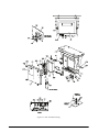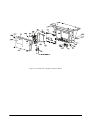
1
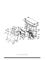
CLS-Series
Cargo Lift Scale
Service Manual
96314
Contents
About This Manual ................................................................................................................................... 1
1.0
Introduction.................................................................................................................................. 1
2.0
Load Cell Replacement................................................................................................................ 2
2.1 Required Tools for Replacing a Load Cell . . . . . . . . . . . . . . . . . . . . . . . . . . . . . . . . . . . . . . . . . . . . . . 2
2.2 Load Cell Relacement . . . . . . . . . . . . . . . . . . . . . . . . . . . . . . . . . . . . . . . . . . . . . . . . . . . . . . . . . . . . 2
3.0
4.0
Junction Box Replacement ....................................................................................................... 12
Lithium-Ion Battery Charge and Replacment ............................................................................ 17
4.0.1
4.1
4.2
4.3
4.4
5.0
Lithium-Ion Battery Specifications . . . . . . . . . . . . . . . . . . . . . . . . . . . . . . . . . . . . . . . . . . . . . . . . . . . . 17
Charging the Lithium-Ion Battery . . . . . . . . . . . . . . . . . . . . . . . . . . . . . . . . . . . . . . . . . . . . . . . . . . .
Calibrating the Lithium-Ion Battery . . . . . . . . . . . . . . . . . . . . . . . . . . . . . . . . . . . . . . . . . . . . . . . . . .
Battery Removal . . . . . . . . . . . . . . . . . . . . . . . . . . . . . . . . . . . . . . . . . . . . . . . . . . . . . . . . . . . . . . . .
Battery Disposal . . . . . . . . . . . . . . . . . . . . . . . . . . . . . . . . . . . . . . . . . . . . . . . . . . . . . . . . . . . . . . . .
18
18
19
20
Board Replacement ................................................................................................................... 21
5.1 CLS-420 CPU Board Replacement . . . . . . . . . . . . . . . . . . . . . . . . . . . . . . . . . . . . . . . . . . . . . . . . . 21
5.1.1
5.1.2
5.1.3
5.1.4
5.1.5
Cable Grounding . . . . . . . . . . . . . . . . . . . . . . . . . . . . . . . . . . . . . . . . . . . . . . . . . . . . . . . . . . . . . . . . .
DC Power Wiring Guidelines . . . . . . . . . . . . . . . . . . . . . . . . . . . . . . . . . . . . . . . . . . . . . . . . . . . . . . . .
Serial Communications . . . . . . . . . . . . . . . . . . . . . . . . . . . . . . . . . . . . . . . . . . . . . . . . . . . . . . . . . . . .
Board Removal . . . . . . . . . . . . . . . . . . . . . . . . . . . . . . . . . . . . . . . . . . . . . . . . . . . . . . . . . . . . . . . . . .
Replacement Parts . . . . . . . . . . . . . . . . . . . . . . . . . . . . . . . . . . . . . . . . . . . . . . . . . . . . . . . . . . . . . . .
21
22
23
24
25
5.2 CLS-920i CPU Board Replacement . . . . . . . . . . . . . . . . . . . . . . . . . . . . . . . . . . . . . . . . . . . . . . . . . 28
5.2.1
5.2.2
5.2.3
5.2.4
5.2.5
5.2.6
5.2.7
5.2.8
5.2.9
5.2.10
5.2.11
5.2.12
5.2.13
6.0
Enclosure Disassembly . . . . . . . . . . . . . . . . . . . . . . . . . . . . . . . . . . . . . . . . . . . . . . . . . . . . . . . . . . . .
Cable Connections . . . . . . . . . . . . . . . . . . . . . . . . . . . . . . . . . . . . . . . . . . . . . . . . . . . . . . . . . . . . . . .
Cable Grounding . . . . . . . . . . . . . . . . . . . . . . . . . . . . . . . . . . . . . . . . . . . . . . . . . . . . . . . . . . . . . . . . .
Serial Communications . . . . . . . . . . . . . . . . . . . . . . . . . . . . . . . . . . . . . . . . . . . . . . . . . . . . . . . . . . . .
Digital I/O . . . . . . . . . . . . . . . . . . . . . . . . . . . . . . . . . . . . . . . . . . . . . . . . . . . . . . . . . . . . . . . . . . . . . .
Installing Option Cards . . . . . . . . . . . . . . . . . . . . . . . . . . . . . . . . . . . . . . . . . . . . . . . . . . . . . . . . . . . .
Enclosure Reassembly . . . . . . . . . . . . . . . . . . . . . . . . . . . . . . . . . . . . . . . . . . . . . . . . . . . . . . . . . . . .
CPU Board Removal . . . . . . . . . . . . . . . . . . . . . . . . . . . . . . . . . . . . . . . . . . . . . . . . . . . . . . . . . . . . . .
Fuse Replacement . . . . . . . . . . . . . . . . . . . . . . . . . . . . . . . . . . . . . . . . . . . . . . . . . . . . . . . . . . . . . . .
Battery Replacement. . . . . . . . . . . . . . . . . . . . . . . . . . . . . . . . . . . . . . . . . . . . . . . . . . . . . . . . . . . . . .
Parts Kit Contents . . . . . . . . . . . . . . . . . . . . . . . . . . . . . . . . . . . . . . . . . . . . . . . . . . . . . . . . . . . . . . . .
Downloading CLS Configuration and User Program Software . . . . . . . . . . . . . . . . . . . . . . . . . . . . . . .
Replacement Parts and Assembly Drawings . . . . . . . . . . . . . . . . . . . . . . . . . . . . . . . . . . . . . . . . . . . .
28
28
28
29
31
31
32
32
32
33
33
33
34
Appendix .................................................................................................................................... 38
5FDIOJDBMUSBJOJOHTFNJOBSTBSFBWBJMBCMFUISPVHI3JDF-BLF8FJHIJOH4ZTUFNT
$PVSTFEFTDSJQUJPOTBOEEBUFTDBOCFWJFXFEBUXXXSMXTDPNPSPCUBJOFE
CZDBMMJOHBOEBTLJOHGPSUIFUSBJOJOHEFQBSUNFOU
© 2007 Rice Lake Weighing Systems. All rights reserved. Printed in the United States of America.
Specifications subject to change without notice.
Version 1.0, August 2007
2
CLS-Series Service Manual
About This Manual
This manual is intended for use by individuals responsible for servicing the CLS-920i and the CLS-420 Cargo
Lift scale.
This manual contains technical instructions and procedures for servicing the CLS Series scales and covers
information on load cell replacement, junction box replacement, replacement parts and troubleshooting
procedures. Any repairs to the indicator include instructions on CPU board and fuse replacement.
This manual does not attempt to cover actual upacking, installation and operating procedures as they are covered
in the CLS-920i Installation Manual, PN 96312, and CLS-420 Installation Manual, PN 96483.
7ARNING
1.0
Some procedures described in this
manual require work inside the indicator
enclosure. These procedures are to be
performed by qualified service personnel
only.
7ARNING
Take all necessary safety precautions
when installing or replacing the scale
parts including wearing safety shoes,
protective eyewear, and using the proper
tools.
Introduction
The CLS Series Cargo Lift scale is a rugged, dependable cargo lift scale that can withstand many years of
repeated use. When mounted on a forklift, the CLS Series can weigh, transfer and collect data in one efficient
operation. It saves operator time, equipment costs and eliminates the middle step.
The CLS Series is used with either Rice Lake’s 920i® HMI digital weight indicator or the 420 digital weight
indicator.
Figure 1-1. CLS Series Cargo Lift Scale
The following sections of this manual deal with any servicing issues that might arise with this product.
Areas described in this manual include:
• Load cell replacement
• Junction box replacement
• CPU board replacement
• Troubleshooting
Introduction
1
2.0
Load Cell Replacement
This section describes procedures for replacing the load cell should it need to be changed. The CLS Series Cargo
Lift Scale uses Rice Lake’s load cell, PN 96198.
The following instructions must be followed exactly to allow for seamless and easy load cell replacement.
7ARNING
2.1
Take all necessary safety precautions when installing or replacing the scale parts including wearing safety
shoes, protective eyewear, and using the proper tools.
Required Tools for Replacing a Load Cell
The following list of tools is necessary for replacing a load cell on the CLS Series Scale. Ensure that you have
these necessary tools handy.
Rice Lake Part #
96196
Item Description
Modified box wrench
Crescent wrench
3/4” Socket wrench, with extensions
Hammer
1-1/8” wrench for overload stop
Chisel
Allen wrench for overload stops
Digital voltmeter (capable of reading millivolts)
Torque wrench
Pry bar
Table 2-1. Required Tools for Replacing a Load Cell
NOTE: Adequate light is necessary to change the load cell. Try to position the forklift close to a good source of natural
light or if not possible, have a good source of lighting available.
2.2
Load Cell Relacement
Figures 2-1 and 2-2 illustrate the parts associated with load cell replacement.
Number
RLWS Part Number
Description
97883
Complete Replacement Parts Kit which includes all of the components listed below.
1
14671
Hex Nut
2
14671
Hex Nut
3
96249
Spherical Washer Set
4
2
Upper Block
5
96249
Spherical Washer Set
6
14671
Hex Nut
7
14665
Jam Nut
8
96199
Flexure Rod
9
14665
Jam Nut
10
96198
Load Cell
11
14665
Jam Nut
12
96199
Flexure Rod
CLS Series Service Manual
Number
RLWS Part Number
13
14665
Jam Nut
14
14671
Hex Nut
15
96249
Spherical Washer Set
16
Description
Lower Block
17
96249
Spherical Washer Set
18
14671
Hex Nut
19
14671
Hex Nut
The following drawing illustrates a side view of the major component parts of the CLS Series Cargo Lift Scale.
#BDL1MBUF
'SPOU1MBUF
6QQFS#MPDL
-PXFS#MPDL Figure 2-1. CLS Series Parts Breakout
Load Cell Replacement
3
Figure 2-2 also illustrates the parts associated with load cell replacement and a replacement parts kit is available
(PN 97883) which contains all of the component parts shown below, in Figure 2-2.
1. Hex Nut
2. Hex Nut
3. Spherical Washer Set
4. Upper Block
5. Spherical Washer Set
6. Hex Nut
7. Jam Nut
8. Flexure Rod
9. Jam Nut
10. Load Cell
11. Jam Nut
12. Flexure Rod
13. Jam Nut
14. Hex Nut
15. Spherical Washer Set
16. Lower Block
17. Spherical Washer Set
18. Hex Nut
19. Hex Nut
Figure 2-2. Pictoral CLS Series Parts Breakout
4
CLS Series Service Manual
Use the following steps to replace a load cell.
1. Raise the forklift carriage just slightly for forklift tine removal.
2. Slide the fork lift tines to the middle of the carriage to allow for removal of tines and set tines aside.
Slide tines to the middle of
scale carriage
Figure 2-3. Forklift Tine Removal
3. Raise the fork lift carriage to a comfortable working height for the load cell replacement.
4. Remove the top hex nut (#1) with a 3/4" torque wrench.
NOTE: It’s okay if the load cell slightly rotates up against the side of the front or back plate of the scale.
Figure 2-4. Removal of Hex Nut (#1 of Parts Breakdown)
5. Loosen jam nut (#7) from the upper block using the special modified box wrench (PN 96196 - supplied
with scale) shown in Figure 2-5 on the following page.
Load Cell Replacement
5
.
Figure 2-5. Modified Box Wrench
6. Loosen jam nut (#13) from the lower block.
7. Remove the top hex nut (#2) and the top spherical washer set (#3).
8. Loosen the two bottom hex nuts (#18 and #19) with a torque wrench.
Figure 2-6. Loosen and Remove Bottom Hex Nut (#18 and #19 on Parts Breakdown)
NOTE: It’s okay if the load cell slightly rotates up against the side of the front or back plate of the scale.
9.
10.
11.
12.
13.
14.
6
Remove the bottom hex nuts (#18 and #19) and the bottom spherical washer set (#17).
Loosen the hex nut located under the upper block (#6).
Loosen the jam nut located on top of the load cell (#9).
Loosen the hex nut (#14) located on top of the lower block.
Loosen the hex nut (#11) on the lower side of the load cell.
Remove the bottom flexure rod (#12) and the top flexure rod (#8) sliding the remaining washer sets (#5
and #15) with it.
CLS Series Service Manual
.
Ensure flexure rod
threads are free of
d e b ri s a n d p a i n t b y
running a nut the full
distance of the rod.
Figure 2-7. Remove Flexure Rod with Nuts and Washers
15. Check the flexure rod threads for smooth operation by running a nut the full distance of the rod making
sure it does not get stuck anywhere along the way. If so, clean off any paint using a wire brush and oil.
16. Oil the spherical washers using a standard machine shop oil.
17. Loosen cable clips and remove the load cell.
Detach load cell
clip away from
back plate of
scale.
Figure 2-8. Load Cell Cable Clips
Load Cell Replacement
7
18. Back off upper and lower overload stops using a 1-1/8" wrench.
Overload
stops looking
at top view.
Figure 2-9. Overload Stops
19. Position a new load cell with its cable facing towards the center and opening of the S-beam facing the
flexures.
Load cell cable should
face towards the
center of the scale.
20. Install the top and bottom flexure rod with hardware ensuring that the flexure rod be oriented with the
short thread of rod facing nearest the load cell.
Short threads
facing nearest the
load cell
Figure 2-10. Installing Flexure into Scale
8
CLS Series Service Manual
21. Insert the load cell and thread flexure rods into top and bottom of the load cell making sure the
appropriate hex nuts, jam nuts, and spherical washers are in the correct order per Figure 2-2 on page 4.
22. Screw in the rod and tighten jam nut but leave approximately two threads exposed outside of the jam nut.
Do both the top and bottom of the load cell.
23. Use hex nuts to position the load cell in the center of the mounting blocks with an equal amount of
flexure rod on top and bottom of the load cell.
24. Tighten the jam nuts on top and bottom of the load cell. Make sure they are tight and completely vertical
to the scale. To accomplish this, you can use a pry bar or chisel to hold the cell straight as illustrated in
Figure 2-11.
Use chisel to hold load
cell straight.
Figure 2-11. Use Chisel to Hold the Load Cell in Straight
25. Install the spherical washer set and hex nut on the bottom flexure rod ensuring that the fat washer is
mounted towards the mounting block.
Figure 2-12. Install Spherical Washer Set
26. Install a flat bladed screwdriver in upper mounting block between the hole and the flexure rod, forcing
Load Cell Replacement
9
the flexure rod in the direction of the flexures.
Insert flat blade
screwdriver here to help
center the flexure rod
Figure 2-13. Centering the Flexure Rod
27. Use a pry bar or chisel to hold the load cell (bottom half of the cell), straight while using a torque wrench
to tighten the bottom hex nut on the lower mounting block to 110 ft/lb. Install the other hex nut on the
bottom of the flexure rod and torque it to 110 ft/lb.
Figure 2-14. Centering the Load Cell Using a Chisel
10
CLS Series Service Manual
Figure 2-15. Tightening the Lower Hex Nut
28. Use the special modified box wrench to tighten the jam nut (#13) on the lower block.
29. Remove the flat bladed screwdriver as used in Step 25 and inspect the flexure rod. The flexure rod needs
to be in the center of the hole. If it is not, use a hammer and an angled diamond chisel to hit the bottom
mounting plate spherical washer set to adjust it to center.
30. Install the spherical washer set (#3) and hex nut (#2) on the top of the upper block.
31. Wire up the load cell cable to the junction box at this time.
32. Make sure that ZTRKBN is set to Off on the indicator.
33. Torque the hex nut (#2) on the upper mounting block until you see 100 lb on the indicator display.
Tighten the lower hex nut (#6) below the upper mounting block using the modified box wrench and try
to get the display as close to zero as possible.
34. Torque the top hex nut (#1) with a torque wrench to 110 ft/lbs. Use a pry bar or chisel to ensure the load
cell stays centered while tightening and doesn’t touch the sides of front or back plate
35. Install the final hex nut on the top mounting plate and torque to 110 ft/lbs. Use a pry bar or chisel to keep
the load cell centered.
36. Tighten the jam nut on the lower mounting block assembly.
37. Zero out the indicator display.
38. Exercise the scale heel to toe by placing a weight (1000 lbs) on the heel then the toe to check if the
assembly was installed correctly. Do this for both sides. If the weight is off, check assemblies.
39. Place a weight in the center of the fork and check side to side values. If they are equal, you are done.
40. Tighten the overload stops when complete.
41. Make sure to turn ZTRKBN to On on the indicator.
Load Cell Replacement
11
3.0
Junction Box Replacement
The CLS Series scale uses a NEMA 4X polycarbonate junction box. The junction box is located between the
front and back panel of the scale and is covered by a metal cover plate on the top of the scale. Use the following
procedures for replacing a junction box on the CLS Series Cargo Lift Scale.
1. Remove the bolt that holds the top metal cover plate in place which conceals the junction box.
Remove bolt that
holds the top cover
plate on the scale to
access the smart
junction box.
Sm a rt J u nc t io n
Box Location
Figure 3-1. Top Cover Plate (scale shown not mounted on the forklift)
2. Remove the top cover plate and set aside.
3. Lift the fork lift to a comfortable working height.
4. Remove the two screws securing the junction box to the scale. See Figure 3-2 for screw location.
Screw locations
Figure 3-2. Screw Locations
12
CLS Series Service Manual
5. Remove the indicator cable from the junction box (not applicable for wireless models).
Remove indicator cable
from junction box (if
using the wired model)
Remove load cell cable
from junction box
Figure 3-3. Junction Box Location Inside the Scale (wireless version shown above)
6. Loosen the load cell clips that hold the load cell cable to the scale back frame and their general location
noted in Figure 2-8 on page 7.
7. Slip the junction box downward out of its current location between the front and back plates of the CLS.
8. Using a phillips head screwdriver, open the junction box cover to expose the inside and set the cover
aside.
Junction Box Replacement
13
Bottom Board Information
J4 Loadcell
connector
J5 Loadcell connector
Figure 3-4. Inside of Junction Box - Bottom Board
The junction box has two boards within the box. To access the bottom board, remove the screws that hold the top
board in place and flip the top board up and back out of the way as the wires that connect the top and bottom
boards are long enough to acommodate this. The bottom board which is shown in Figure 3-4 connects the wiring
for both load cells one and two. Table 3-1 lists the wiring assignments for the bottom board.
9. Reconnect the wires to the bottom board per Figure 3-4, Figure 3-5, and Table 3-1 listed below.
J4 Wiring Connector
(Cell #1 - the left cell as viewed from the
forklift drivers seat)
J4 Function
1
+ SIGNAL
2
- SIGNAL
3
+ EXCITATION
4
- EXCITATION
5
SHIELD
J5 Wiring Connector
(Cell #2 - the right cell as viewed from the
forklift drivers seat)
J5 Function
1
+ SIGNAL
2
- SIGNAL
3
+ EXCITATION
4
- EXCITATION
5
SHIELD
J8 Wiring Connector
(From the MS Connector)
J8 Function
1
+ V (Red)
2
- V (Black)
Table 3-1. Load Cell Wiring
14
CLS Series Service Manual
J4 - W iring
for the right
load cell #2
as viewed
from
the
driver’s seat
Exits out
to right
cell #2
Exits out to
left cell #1
J5 - Wiring for
the left load cell
#1 as viewed
from the driver’s
seat
Figure 3-5. Bottom Board Wiring
Once wiring is complete, place the upper board back and secure screws holding the upper board.
Upper/Top Board Information
The second board, or the upper board is pictured in Figure 3-6.
Figure 3-6. Inside of Junction Box - Top Board
The wiring from the bottom board is then brought up to be wired into the top board as shown in Figure 3-6,
connecting into J3 and J6 connectors.
Junction Box Replacement
15
.Table 3-2 shows the wiring to the top board connections.
J3 Wiring Connector
(From the MS connector)
Function and (Wire Color)
1
TX1 (blue)
2
RX1 (white)
3
GND (green)
4
TX2 (N/C)
5
RX2 (N/C)
6
GND (N/C)
J6 Wiring Connector
(From the battery - wirless version only)
Function and (Wire Color)
1
KEY (N/C)
2
POS (red)
3
CLOCK (blue)
4
DATA (brown)
5
TEMP (green)
6
NEG (black)
Table 3-2. Top Board Wiring Connections
NOTE: J6 wiring is only used in the wireless version of the CLS series and goes directly to the battery box.
16
CLS Series Service Manual
4.0
Lithium-Ion Battery Charge and Replacment
If using a wireless version of the CLS Series Cargo Lift Scale, the CLS scale uses a supplied lithium-ion battery
to supply power to the indicator. The lithium-ion battery is located on the top of the cover plate in a painted
enclosure.
Replacement part numbers are as follows:
RLWS Part Number
Description
96343
Lithium-Ion Battery
96344
2-Bay Battery Charger
96345
10-Bay Battery Charger
Table 4-1. Battery Replacement Parts
Figure 4-1. Lithium-Ion Battery Location
4.0.1
Lithium-Ion Battery Specifications
Nominal Capacity
6600 mAh
Nominal Voltage
11.1 V
Charging Method
Constant Current
Constant Voltage
Charging Voltage
12.6 V
Charging Current
4.0 A
Charging Time
100% @ 8 hours
Ambient Temperature
Charge
0º - +40ºC (32º -104ºF)
Discharge
-20º - +60ºC (-4º -140ºF)
Storage
-20º - +50ºC (-4º -122ºF)
Weight (Maximum)
Dimensions (Maximum)
430 g
Depth
22.80 mm
Length
214.0 mm
Volumetric Energy Density
466 Wh/I
Gravimetric Energy Density
167 Wh/kg
Maximum Hours of Charge
24 hours
Nominal Capacity
6600 mAh
Table 4-2. Battery Specifications
Lithium-Ion Battery Charge and Replacment
17
4.1
Charging the Lithium-Ion Battery
The lithium-ion battery comes with a two-bay, level-3 stand alone smart battery charger, a DC power jack, and a
AC power cord as shown in Figure 4-2.
To calibrate the
battery pack,
press
the
button on front
label.
Figure 4-2. Two-Bay Battery Charger and Parts for the Lithium-Ion Battery
The average charge time for the battery is eight hours each.
Use the following steps to charge the battery prior to use:
1. Insert the plug end of the power cable into the DC power jack on the battery charger and the AC plug
into an outlet.
2. Insert battery into the bay.
3. There is one LED indicator in front of each bay which will illuminate to indicate the status of the battery
as follows:
Signal
Description
Off
No Battery
Green Flashing
Fast Charging
Green Solid
Fully Charged
Yellow Flashing
Recalibrating
Yellow/Green Alternating
Recalibrating
Yellow Solid
Standby
Red Flashing
Error
Table 4-3. Battery Charging LED Signals
4.2
Calibrating the Lithium-Ion Battery
In order to keep the battery fuel gauge as accurate as possible, it is necessary to run the pack through a
recalibration cycle on a quarterly basis. To do this, place the battery in the left bay of the charger and press the
button on the front label (see Figure 4-2). This will initiate the recalibration sequence in the left bay only. The
process can take up to nine hours to complete and a recommended recalibration should be done once a month to
keep the battery accurate.
18
CLS Series Service Manual
4.3
Battery Removal
The lithium-ion battery itself is housed inside of the battery box which is located on the top plate of the scale and
is encased in a foam core protecting it from vibration.
Figure 4-3. Lithium-ion Battery Box Opened
Figure 4-4 shows how to pull the lithium-ion battery out of the battery box.
Figure 4-4. Pulling the Lithium-Ion Battery Out
Lithium-Ion Battery Charge and Replacment
19
4.4
Battery Disposal
When using Lithium-ion batteries, be sure to observe the following precautions for disposal as stated in the
material safety data sheet regarding lithium-ion batteries.
20
CLS Series Service Manual
5.0
Board Replacement
Use the following procedures in the event that the CPU board on either the 420 or the 920i need to be replaced.
Board replacement for the 420 indicator is covered in Section 5.1 and board replacement for the 920i indicator is
covered in Section 5.2.
5.1
CLS-420 CPU Board Replacement
The indicator enclosure must be opened to connect cables for load cells, communications, digital inputs, and
analog output.
Warning
5.1.1
The 420 has an on/off switch for the load cells and processor functions. Before opening the unit, ensure the
power cord is disconnected from the forklift battery power source.
Cable Grounding
Except for the power cord, all cables routed through
the cord grips should be grounded against the
indicator enclosure. Do the following to ground
shielded cables:
• Use the lockwashers, clamps, and kep nuts
provided in the parts kit to install grounding
clamps on the enclosure studs adjacent to cord
grips. Install grounding clamps only for cord
grips that will be used; do not tighten nuts.
• Route cables through cord grips and
grounding clamps to determine cable lengths
required to reach cable connectors. Mark
cables to remove insulation and shield as
described below:
• For cables with foil shielding, strip insulation
and foil from the cable half an inch (15 mm)
past the grounding clamp (see Figure 5-1).
Fold the foil shield back on the cable where
the cable passes through the clamp. Ensure
silver (conductive) side of foil is turned
outward for contact with the grounding
clamp.
• For cables with braided shielding, strip cable
insulation and braided shield from a point just
past the grounding clamp. Strip another half
inch (15 mm) of insulation only to expose the
braid where the cable passes through the
clamp (see Figure 5-1).
• For load cell cables, cut the shield wire just
past the grounding clamp. Shield wire
function is provided by contact between the
cable shield and the grounding clamp.
• Route stripped cables through cord grips and
clamps. Ensure shields contact grounding
clamps as shown in Figure 5-1. Tighten
grounding clamp nuts.
• Finish installation using cable mounts and ties
to secure cables inside of indicator enclosure.
/05&*OTUBMMMPDLXBTIFST
mSTUBHBJOTUFODMPTVSF
VOEFSHSPVOEJOHDMBNQ
$PSEHSJQ
*OTVMBUFEDBCMF
'PJMTJMWFSTJEFPVU
4IJFMEXJSFDVU
#SBJE
$VUJOTVMBUJPOIFSF
GPSCSBJEFEDBCMFT
(SPVOEJOHDMBNQ
$VUJOTVMBUJPOIFSF
GPSGPJMTIJFMEFEDBCMFT
-FOHUIPGGPJMCFGPSFGPMEJOH
CBDLPODBCMFJOTVMBUJPO
Figure 5-1. Grounding Clamp Attachment for
Foil-Shielded and Braided Cabling
Board Replacement
21
*41
%$*/165
/PSNBM
3
$
3
$
'
+
+
7
$
$
+
104
3
"%
3
3
$
6
$
$
+
"/"-0(
065165
015*0/$"3%
6
6
3
6
3&4&5
$
.JDSP
QSPDFTTPS
3
+.1
6
0/
$
3
3
(/%
$
$
6
(%
104
)#
"/"
.&.
95
104
+1
6
3
3
$
$
+1
%*41-":
%3*7&34
3
$
6
6
104
,&:1"%
$0//&$503
6
0''
$
73
6
"%$0/7&35&3
3 "7
$
+1
*
+1
53
%*
0''
4*(
4*(
4&/
4&/
&9$
&9$
%*
%*
(OE
3Y%
574 574 574 574 574 574
5Y%
(OE
3Y%
5Y%
N"
(OE
(OE
(OE
%0
%0
7
N"
%*
%'#
3
$
(&
53
-&%
5&45
.&$$"
$
3
-&%
%'#
%0
%0
6
%
+
48
4&561
+
%*(065
+
4&3*"-
+
&%1
34
+
%*(*/
+
-0"%$&--
Figure 5-2. 420 CPU and Power Supply Board with Analog Output Option Card
8JSF"TTFNCMZ
1/
UP+PO
$16#PBSE1/
*/
(/%
$)"
Figure 5-3. 420 DC Power Supply
5.1.2
DC Power Wiring Guidelines
Based on:
• 8 x 350Ω
• Analog output installed
• Digital outputs sourcing 20mA each
• Drawing maximum current at 7.5 VDC from the DC/DC power supply
22
,&:1"%
$0//&$503
+
$
$
CLS Series Service Manual
(OE
(OE %$065
3&.05&
4&561
48*5$)
NOTES:
DC power wiring to the indicator should be 18 AWG to 14
AWG for DC+, DC-, and earth ground conductors.
The indicator will be connected directly to the battery of
the forklift. Ensure the type and style of forklift and the
type of power it provides will be compatible with the
indicator. Most propane, gas, and diesel fueled forklifts
provide 12 volts of power. Some diesel models also
provide 24 volts and electric forklifts provide 36 to 48
volts of power. The CLS-Series scales work best with
12-36 VDC power source.
In longer power cable runs, voltage drop over the power
conductor needs to be considered. See table and formula
below to compute voltage drop.
VDROP = (2.85A)(xΩ / 1000ft)(length of run in ft.)
2.85A = maximum current draw from DC/DC power
supply
xΩ = Ohms from Table 5-1
Wire Gauge
(AWG)
Cable
Impedance
(OHMS/1000ft)
14
2.252Ω
15
3.184Ω
16
4.016Ω
17
5.064Ω
18
6.385Ω
Table 5-1. Cable Impedance
NOTE: DC voltage supplied to DC/DC power supply
should not be less than 9VDC. Using larger gauge
wire will result in less voltage drop.
Example:
100ft run with 18 AWG wire
VDROP = (2.85A)(6.385Ω / 1000ft)(100 ft)
VDROP = 1.82V
12VDC will drop to 10.18V after 100ft run.
5.1.3
The EDP port supports full duplex RS-232
communications only; the serial port provides either
active 20 mA output or duplex RS-232 transmission.
Both ports are configured using the SERIAL menu.
See Section 3.0 on page 13 for configuration
information.
Port
Connector
Pin
EDP/RS-232
(J-Box
connector)
J3
1
TxD
2
RxD
3
Gnd
Serial Port
J4
1
TxD
2
RxD
3
Gnd
4
20mA+
5
20mA–
6
Gnd
Table 5-2. J3 and J4 Pin Assignments
Digital inputs can be set to provide several indicator
functions, including all keypad functions. The inputs
are active (on) with low voltage (0 VDC) and can be
driven by TTL or 5V logic without additional
hardware. Use the DIG IN menu to configure the
digital inputs. LED’s on the CPU board light when
digital inputs are active.
Digital outputs are typically used to control relays that
drive other equipment. Outputs are designed to sink
not source, switching current. Each output is a
normally open connector circuit, capable of sinking
250 mA when active. Digital outputs are wired to
switch relays when the digital output is active (low, 0
VDC) with reference to 5 VDC supply. LEDs on the
CPU board light when the digital outputs are active.
Port
Connector
Pin
Label
Digital Input
J2
1
DI 1
2
DI 2
3
Gnd
1
Gnd
2
DO 1
3
DO 2
4
+5V
Serial Communications
Using on of the six-position connectors, provided in
the parts kit, wire the serial communications cables to
J4. Connector J3 provides connections for the
EDP/RS-232 port. Connect communications cables to
connectors J3 and J4 as shown in Table 2-3.
Once cables are attached, reconnect J3 and J4 to the
headers on the board (see Figure 5-2). Use cable ties
to secure serial cables to the inside of the enclosure.
Label
Digital
Output
J6
Table 5-3. J2 and J6 Pin Assignments
Board Replacement
23
5.1.4
Board Removal
If you must remove the 420 CPU board, use the
following procedure:
1. Disconnect power to the indicator. Remove
the screws that hold the backplate to the
enclosure body, then lift the backplate away
from the enclosure and set aside.
2. Disconnect power supply cable from
connector J7 on the 420 CPU board.
3. Unplug connectors J1 (load cell cable), J2
(digital inputs), J3 (EDP/RS-232), J4 (serial
communications), J6 (digital outputs), and
J10 & J11 (keypad ribbon cables). If an
analog output board is installed, disconnect
the analog output cable. See Figure 5-2 on
page 22 for connector locations.
4. Remove the five screws from the CPU board,
then lift the board out of the enclosure.
To replace the CPU board, reverse the above
procedure. Be sure to reinstall cable ties to secure all
cables inside the indicator enclosure.
24
CLS Series Service Manual
5.1.5
Replacement Parts
Table 5-4 lists replacement parts for the 420, including all parts referenced in Figures 5-4 and 5-5.
Ref
Number
PN
1
14862
Screws 8-32NC x 3/8 (4)
2
45042
Sealing washers (4)
3
84387
Backplate (1)
4
84388
backplate gasket (1)
5
14839
Screws 6-32NC x 1/4 (9)
6
85123
CPU and display board assembly (1)
7
84386
Enclosure (1)
8
15148
1/4-20 lockwashers, spacers
9
68403
Four-cornered wing knobs for tilt stand (2)
10
Description (Quantity)
Figure
Figure 5-5 on page 27
Mounting stand (1)
11
44676
Sealing washer (1)
12
42640
Screws 1/4-28NF X 1/4 (2)
13
19538
Cable grip plugs (2)
14
15626
Cable grips (2)
15
30375
Nylon seal rings for cable grips (2)
17
84389
Power supply bracket (1)
18
76556
Power supply switch (1)
85554
Power supply, DC/DC converter
20
84397
Overlay panel (1)
21
68216
Rice Lake nameplate (1)
22
85151
Power supply ribbon cable (1)
23
16892
Earth ground label (1)
24
15134
Lock washer, No 8, Type A (3)
25
45043
Ground wire 4 in, No. 8 (1)
27
14626
Kep nuts, 8-32NC Hex (5)
28
15627
Locknuts (3)
30
85494
Protective cover (1)
32
15376
Standoffs, male - female (2)
85791
Fuse, 2.5 Amp 5x20mm
96915
Power cable assembly
35287
Fuse, Slo-blo, 5 Amp 3AG for power cable assy.
Figure 5-4 on page 26
Figure 5-5 on page 27
Table 5-4. CLS-420 Indicator Replacement Parts
Board Replacement
25
Figure 5-4. 420 Assembly Drawing
26
CLS Series Service Manual
Figure 5-5. 420 Enclosure, Backplate and CPU Board
Board Replacement
27
5.2
CLS-920i CPU Board Replacement
5.2.1
Enclosure Disassembly
The 920i indicator enclosure must be opened to install
option cards and to connect cables for installed option
cards.
7ARNING
The 920i has no on/off switch. Before
opening the unit, ensure the power cord is
disconnected from the forklift power
source.
Ensure power to the indicator is disconnected, then
place the indicator face-down on an antistatic work
mat. Remove the screws that hold the backplate to the
enclosure body, then lift the backplate away from the
enclosure and set it aside.
5.2.2
*OTVMBUFEDBCMF
'PJMTJMWFSTJEFPVU
4IJFMEXJSFDVU
#SBJE
$VUJOTVMBUJPOIFSF
GPSCSBJEFEDBCMFT
(SPVOEJOHDMBNQ
$VUJOTVMBUJPOIFSF
GPSGPJMTIJFMEFEDBCMFT
-FOHUIPGGPJMCFGPSFGPMEJOH
CBDLPODBCMFJOTVMBUJPO
Figure 5-6. Grounding Clamp Attachment for
Foil-Shielded and Braided Cabling
•
•
Cable Grounding
Except for the power cord, all cables routed through
the cord grips should be grounded against the
indicator enclosure. Do the following to ground
shielded cables:
• Use the lockwashers, clamps, and kep nuts
provided in the parts kit to install grounding
clamps on the enclosure studs adjacent to cord
grips. Install grounding clamps only for cord
grips that will be used; do not tighten nuts.
• Route cables through cord grips and
grounding clamps to determine cable lengths
required to reach cable connectors. Mark
cables to remove insulation and shield as
described below:
• For cables with foil shielding, strip insulation
and foil from the cable half an inch (15 mm)
past the grounding clamp (see Figure 5-6).
Fold the foil shield back on the cable where
the cable passes through the clamp. Ensure
silver (conductive) side of foil is turned
outward for contact with the grounding
clamp.
• For cables with braided shielding, strip cable
insulation and braided shield from a point just
past the grounding clamp. Strip another half
inch (15 mm) of insulation only to expose the
braid where the cable passes through the
clamp (see Figure 5-6).
28
$PSEHSJQ
Cable Connections
The universal model of the 920i provides six cord
grips for cabling into the indicator: one for the power
cord, five to accommodate cabling for option cards.
Install plugs in all unused cord grips to prevent
moisture from entering the enclosure.
5.2.3
/05&*OTUBMMMPDLXBTIFST
mSTUBHBJOTUFODMPTVSF
VOEFSHSPVOEJOHDMBNQ
CLS Series Service Manual
•
For load cell cables, cut the shield wire just
past the grounding clamp. Shield wire
function is provided by contact between the
cable shield and the grounding clamp.
Route stripped cables through cord grips and
clamps. Ensure shields contact grounding
clamps as shown in Figure 5-6. Tighten
grounding clamp nuts.
Finish installation using cable ties to secure
cables inside of indicator enclosure.
Serial Communications
Signal
Port
J11
1
GND
2
RS-232 RxD
3
RS-232 TxD
1
for
Scanner
1
GND / –20mA OUT
2
RS-232 RxD
3
RS-232 TxD
4
+20mA OUT
1
GND / –20mA OUT
2
RS-232 RxD
3
RS-232 TxD
4
+20mA OUT
5
RS-485 A
6
RS-485 B
J10
%#$POOFDUPS
GPS1PSU+
Figure 5-7. Interface Board Connections
DB-9 Pin
Signal
2
TxD
3
RxD
5
GND
7
CTS
8
RTS
Table 5-6. DB-9 Connector Pin Assignments
3
+
0QUJPOBM
,FZCPBSE$POOFDUPS
-$%
$POUSBTU
73
$-,
J9
-$%$POUSBTU
+
4
for
Junction
Box
+
%*/
$POOFDUPS
%#$POOFDUPS
3JCCPO$BCMF$POOFDUPS
UP$16#PBSE+
Pin
%"5
Connector
%*/$POOFDUPSGPS
143FNPUF,FZCPBSE
3&5
The four communications ports on the 920i CPU
board support full duplex RS-232, 20 mA output, or
RS-485 communications at up to 115200 bps.
To attach serial communications cables, route the
cable through the cord grip and ground the shield wire
as described in Section 5.2.3 on page 28. Remove the
serial connector from the CPU board and wire to the
connector. Once cables are attached, plug the
connector into the header on the board. Use cable ties
to secure serial cables to the inside of the enclosure.
Table 5-5 shows the pin assignments for Ports 1, 3,
and 4. Port 2 provides DIN-8 and DB-9 connectors for
remote keyboard attachment of PS/2-type personal
computer keyboards (see Figure 5-7). The DB-9
connector pin assignments for Port 2 are shown in
Table 5-6; see Sec tion 10.3 on p age 1 09 fo r
information about the PS/2 keyboard interface.
183
5.2.4
+
4FUVQ
4XJUDI
1#
Figure 5-8. Interface Board, Top View
Table 5-5. Serial Port Pin Assignments
Serial ports are configured using the SERIAL menu.
See Section 3.2.2 on page 33 for configuration
information.
An optional dual-channel serial communications
expansion card, PN 67604, is also available. Each
serial expansion card provides two additional serial
ports, including one port that supports RS-485
communications. Both ports on the expansion card
can support RS-232 or 20mA connections.
Board Replacement
29
+
#"55&3:
+
015*0/$"3%
$0//&$503
4-05
.FNPSZ$BSE
4-05
4FSJBM&YQBOTJPO
48
108&3
4611-:
015*0/$"3%
$0//&$503
+
&91"/4*0/#64
7%$
(/%
(/%
o7%$
+
1*&;0
#6;;&3
015*0/
+
015*0/$"3%-0$"5*0/4
+1
1035
3&.05&
4&561
48*5$)
+
(/%
343Y%
345Y%
+
1035
(/%oN"065
343Y%
345Y%
N"065
345Y%
345Y%¦
+ 1035 +
1035
48
#005
.0%&
+ %*(*5"-*0
7%$
(/%
%*0
%*0
%*0
%*0
+
(/%oN"065
343Y%
345Y%
N"065
*/5&3'"$&
#0"3%
$0//&$5*0/
Figure 5-9. 920i CPU Board, Showing Option Card Locations
30
CLS Series Service Manual
5.2.5
Digital I/O
Digital inputs can be set to provide many indicator
functions, including all keypad functions. Digital
inputs are active low (0 VDC), inactive high (5 VDC).
Digital outputs are typically used to control relays that
drive other equipment. Outputs are designed to sink,
rather than source, switching current. Each output is a
normally open collector circuit, capable of sinking 24
mA when active. Digital outputs are wired to switch
relays when the digital output is active (low, 0 VDC)
with reference to a 5 VDC supply.
Table 5-7 shows the pin assignments for connector J2.
J2 Pin
J2 Signal
1
+5 VDC
2
GND
3
DIO 1
4
DIO 2
5
DIO 3
6
DIO 4
+
+
Figure 5-10. Installing Option Card Onto CPU Board
8JSFMFTT"OUFOBF
Table 5-7. J2 Pin Assignments (Digital I/O)
Digital inputs and outputs are configured using the
DIG I/O menu. See Section 3.2.6 on page 46 for
configuration information.
An optional 24-channel digital I/O expansion card,
PN 67601, is available for applications requiring more
digital I/O channels.
5.2.6
Installing Option Cards
Each option card is shipped with installation
instructions specific to that card. The general
procedure for all option cards is as follows:
#AUTION
$5 */%*$"5&4
015*0/$"3%
$"#-&5*&4
$5
$5
16-4&*/165
$"3%
%6"-"%
$"3%
Option cards are not hot-pluggable.
Disconnect power to the 920i before
installing option cards.
1. Disconnect power to the indicator. Remove
backplate as described in Section 2.2 on page 6.
2. Carefully align the large option card connector
with connector J5 or J6 on the CPU board (see
Figure 5-10). Press down to seat the option card
in the CPU board connector.
3. Use the screws provided in the option kit to
secure the other end of the option card to the
threaded standoffs on the CPU board (see
Figure 5-10).
4. Make connections to the option card as required.
Use cable ties to secure loose cables inside the
enclosure as shown in Figure 5-11. When
installation is complete, reassemble the
enclosure as described in Section 5.2.7 on
page 32.
$5
$5
.FNPSZ$BSE
8J1PSU
4FSJBM$BSE
Figure 5-11. Installed Option Cards, Showing Secured
Cables
The 920i automatically recognizes all installed option
cards when the unit is powered on. No
hardware-specific configuration is required to identify
the newly-installed card to the system.
Board Replacement
31
Expansion Board Serial Port Assignments
5.2.8
Serial port numbers are reserved for each option card
slot, regardless of the type of cards actually installed.
Two port numbers are reserved for each slot that could
contain a dual-channel serial expansion card.
Table 5-8 shows the port numbers assigned to each
slot.
2
7–8
3
9–10
4
11–12
5
13–14
6
15–16
7
17–18
8
19–20
9
21–22
10
23–24
11
25–26
12
27–28
5.2.9
13
29–30
14
31–32
Fuses for the universal and deep enclosure models of
the 920i are located under a cover plate on the outside
of the enclosure. Remove the cover plate, replace the
fuses, and reinstall the cover plate (see Figure 5-13).
Slot Number
Serial Port Assignments
CPU board
1–4
1
5–6
Table 5-8. Expansion Board Serial Port Assignments
5.2.7
Fuse Replacement
Enclosure Reassembly
#AUTION
Once cabling is complete, position the backplate over
the enclosure and reinstall the backplate screws. Use
the torque pattern shown in Figure 2-12 to prevent
distorting the backplate gasket. Torque screws to 15
in-lb (1.7 N-m).
CPU Board Removal
If you must remove the 920i CPU board, use the
following procedure:
1. Disconnect power to the indicator. Remove
backplate as described in Section 2.2 on
page 6.
2. Unplug connectors J9, J10, and J11 (serial
communications), J2 (digital I/O), P1 (power
supply), and connectors to any installed
option cards.
3. Remove any installed option cards.
4. Remove the five phillips head screws and two
kep nuts from the CPU board.
5. Gently lift up the CPU board, then disconnect
connectors J12 (power to display), J4 (ribbon
cable, J3 (keypad connector), then the cable
J8 (Port 2 serial port).
6. Remove CPU board from the enclosure. If
necessary, cut cable ties to shift cables out of
the way.
To replace the CPU board, reverse the above
procedure. Be sure to reinstall cable ties to secure all
cables inside the indicator enclosure.
To protect against the risk of fire, replace
fuses only with same type and rating fuse.
See Section 10.14 on page 126 for
complete fuse specifications.
#AUTION
Interface board and fuse access cover
plates must be in place for use in NEMA
4X/IP66 applications.
l
5PSRVFGVTFBOEJOUFSGBDFCPBSEBDDFTTDPWFSTUP
JOMC/N
5 P S R VF C B D LQ MB UF T D S F XT
UP JO MC / N Figure 5-12.
32
CLS Series Service Manual
1PXFS4XJUDI
*OUFSGBDF#PBSE
Figure 5-13. Interface Board and Fuse Locations,
Universal Model
5.2.10
Battery Replacement
The lithium battery on the CPU board maintains the
real-time clock and protects data stored in the system
RAM when the indicator is not connected to AC
power.
Data protected by the CPU board battery includes
time and date, truck and tare memory, onboard
database information, and setpoint configuration.
Use iRev to store a copy of the indicator configuration
on a PC before attempting battery replacement. If any
data is lost, the indicator configuration can be restored
from the PC.
PN
Description
15144
Nylon washers for tilt stand, 1/4 x 1 x 1/16 (2,
universal model only)
68403
Wing knobs for tilt stand (2)
Table 5-9. Parts Kit Contents (Continued)
5.2.12
Downloading CLS
Program Software
Configuration
and
User
NOTE: Memory option card data is also protected by a
lithium battery. All database information stored on a memory
card is lost if the memory card battery fails.
Watch for the low battery warning on the LCD display
and periodically check the battery voltage on both the
CPU board and on any installed memory option cards.
Batteries should be replaced when the indicator low
battery warning comes on, or when battery voltage
falls to 2.2 VDC. Life expectancy of the battery is ten
years.
See Figure 5-9 on page 30 for CPU board battery
location and orientation (positive side up).
#AUTION
5.2.11
Risk of explosion if battery is replaced
with incorrect type. Dispose of batteries
per manufacturer instruction.
Parts Kit Contents
Table 5-9 lists the parts kit contents for the universal
model of the 920i.
PN
Description
14626
Kep nuts, 8-32NC (4)
14862
Machine screws, 8-32NC x 3/8 (12)
75068
Sealing washers (14)
15133
Lock washers, No. 8, Type A (4)
30623
Machine screws, 8-32NC x 7/16 (2)
15631
Cable ties (4–single A/D, 6–dual A/D)
15665
Reducing glands for 1/2 NPT cord grips (2)
15887
6-position screw terminal for load cell connection
(1–single A/D, 2–dual A/D)
19538
Cord grip plugs (4–single A/D, 3–dual A/D)
42350
Capacity label (1–single A/D, 2–dual A/D)
53075
Cable shield ground clamps (4)
70599
6-position screw terminals for J2 and J10 (2)
71126
4-position screw terminal for J9 and optional
keyboard connection (2)
71125
3-position screw terminal for J11 (1)
42149
Rubber feet for tilt stand (4)
Table 5-9. Parts Kit Contents
Board Replacement
33
5.2.13
Replacement Parts and Assembly Drawings
Table 5-10 lists replacement parts for the 920i universal enclosure model, including all parts referenced in
Figures 2-14 through 2-16.
Ref Number
PN
Description (Quantity)
1
66502
Overlay (1)
2
14956
Cap screw, 1/4-NCx1/2 (2)
3
15148
Lock washer, 1/4 regular (2)
4
68598
Protective lense (1)
5
67614
LCD display (1)
6
67886
Standoffs, short (4)
7
68661
Standoffs, long (2)
8
67612
CPU board (1)
9
14618
Kep nuts, 4-40NC (10)
10
94392
Power supply, bracket (1)
11
97468
Mounting plate assembly (1)
12
94392
Backplate (1)
13
14624
Lock nuts, 6-32NC, nylon (2)
14
14822
Machine screws, 4-40NC x 1/4 (13)
15
67530
Interface board connector plate (1)
16
67535
Interface board gasket (1)
17
14862
Machine screws, 8-32NC x 3/8 (4)*
18
75062
Sealing washers (12)*
19
32365
Setup switch access screw, 1/4 x 20NC x 1/4 (1)
20
42640
Machine screw 1/4-28NF x 1/4 (1)
21
15626
Cable grips, PG9 (3)
22
15627
Lock nuts, PCN9 (3)
23
30375
Nylon seal rings for PG9 cord grips (3)
24
97081
920i Enclosure (1)
25
15134
Lock washers, No. 8, Type A (3)
26
14626
Kep nuts, 8-32NC (3)*
27
45043
Ground wire, 4 in w/ No. 8 eye connector (1)
28
97464
Cover plate (1)
2-14
29
97476
Cable assembly DC power input DC/DC +/-6V supply(1)
2-14
30
15631
Cable tie, 3-in nylon (1)*
2-16
31
97474
Power cord assembly, 115 VAC and 230 VAC North American units (1)
2-14
2-14
2-15
69998
Power cord assembly, 230 VAC European units (1)
32
67796
Power supply cable assembly, to CPU board (1)
2-15
33
68662
Ribbon cable to interface board, universal (1)
2-15
Table 5-10. Replacement Parts
34
See Figure
CLS Series Service Manual
—
Ref Number
PN
Description (Quantity)
34
16892
Ground/Earth label (1)
35
15650
Cable tie mounts, 3/4 in. (1)
36
68216
Rice Lake nameplate (1)
37
67755
Brass spacer (1)
38
57241
Gasket, size 14 (1)
39
67532
Backplate gasket (1)
40
53308
Model/serial number label (1)
41
68532
Single-channel A/D card (1, can be single- or dual-channel A/D)
See Figure
2-15
—
68533
Dual-channel A/D card (1, can be single- or dual-channel A/D)
42
67609
Memory card
2-15
43
71027
Fuses (115 VAC models), 2 A Time-Lag TR5 (2)
71026
Fuses (230 VAC models), 2 A Time-Lag TR5 (2)
45
67869
Interface board (1)
46
14832
Machine screws, 4-40NC x 3/8 (2)
47
14845
Machine screws, 6-32NC x 1/4 (8)
50
15628
Cord grips, 1/2 NPT (1)
52
30376
Nylon seal rings for 1/2 NPT cord grips (1)
53
15630
Lock nuts for 1/2 NPT cord grips (1)
54
70069
3V Lithium coin battery
2-16
55
69898
Nylon spacers (4)
2-14
—
66502
Switch panel membrane (1)
57
70599
6-position screw terminal connector (2)
96915
Power cable assembly, fused power
35287
Fuse, Slo-blo, 5 Amp, 3AG
2-14
44
2-15
2-14
48
Table 5-10. Replacement Parts (Continued)
Board Replacement
35
Figure 5-14. 920i Assembly Drawing
36
CLS Series Service Manual
Figure 5-15. 920i Front and Bottom Enclosure
Figure 5-16. Zigbee Module Option
Board Replacement
37
6.0
Appendix
The following table lists the parts available for the CLS-Series scale.
Drawing Number
Rice Lake Part Number
Item Description
1
Serial Number Label
1
2
RLWS logo?
1
3
Flat #6 Washer
2
4
Jam Nut 3/4 - 16UNF
4
5
SHCS set 3/4-16 x 2, 1/2” long
4
Spherical Washer Set
8
Cable clamp
8
HHCS, 5/8-11UNC-28 x 1” long, cover plate bolt
1
9
SHCS, #6-32UNC-2A x 1,1/8 long ss
2
10
SHCS, 3/8-16UNC-2A x 1/2 long
2
11
SHCS, 1/2-13UNC-2A x 1,1/2 flexures
16
6
96249
7
8
92813
13
92810
SHCS, 5/8-11UNC-2A x 2.5” long
8
14
14671
Hex Nut, 1/2 - 20UNF-2B
12
15
Jam nut 1-8UNC-2B
2
16
Lock washer #6
2
17
Side flexure
4
23
96199
Flexure rod
4
26
96647
Bottom cleat
2
Junction box spacer plate
1
Reinforced cover plate
1
29
Shim bolt
2
30
Weld assembly
1
31
Junction box
1
Load cell
2
Screw, drive #4 x 5/16” SS
2
Jam Nut, 1/2 - 20
8
SHCS, #6-32UNC x 1-1/8 long SS Low Head
2
96251
Top Cleat
1
96252
Expansion Cable from j-box to indicator
1
27
28
32
97118
96198
33
35
14665
36
Table 6-1. CLS Replacement Parts
The following page shows the parts breakout of the CLS-Series Cargo Lift Scale.
38
Quantity
CLS Series Service Manual
Appendix
39
6.1
CLS-Series Specifications
Cargo Lift Scale
Scale Capacity:
Safe Overload:
Ultimate Overload:
Scale Power:
Material/Finish:
Scale Warranty:
Scale Approval:
5,000 lb
200%
5:1 capacity
Wired Version:
supplied by coiled interface cable from indicator
Wireless Version:
supplied by one lithium-ion Smart battery (SMBus revision 1.1 fully compliant)
Painted mild steel
Two-year limited warranty
NTEP-certified at 1,000 divisions, Class III, COC#06-074
420 Indicator
Display:
Power - DC:
0.8” (20 mm), 6-digit red Light Emitting Diode (LED) display, 7-segment digits
Line voltages: 10-60 VDC DC input
Power consumption: 0.75 amp Max
Fused at 5.0 amps
Rating/Material:
304 stainless steel
Status annunicators:
Operating temp:
Designators for: center of zero, stand still, gross, net, lb, kg, count, tare
Legal: 14 F to 104 F (-10 C to 40 C)
Industrial: 14 F to 122 F (-10 C to 50 C)
Contains FCC ID: OUR-XBEE/OUR-XBEEPRO
Contains Model XBee-PRO Radio, IC: 4214A-XBEEPRO
Operating frequency: ISM 2.4 GHz
Two-year limited warranty
NTEP-certified at 10,000 divisions, Class III/IIIL, CC#04-074
Zigbee Connection:
Warranty:
Approvals:
920i Indicator
Display:
Power - DC:
Material:
Operating temp:
WLAN Option:
Zigbee connection:
Warranty:
Approvals:
4.6” W x 3.4” H (116 mm W x 86 mm H), 320 x 240 pixel VGA Liquid Crystal Display (LCD) module with
adjustable contrast
Line voltages: 10-60 VDC DC input
Power Consumption: 1.5 amp Max
Fused at 5.0 amps
304 stainless steel
Legal: 14 F to 104 F (-10 C to 40 C)
Industrial: 14 F to 122 F (-10 C to 50 C)
Contains FCC ID: R68WIPORATG
Range: Up to 328 feet indoors
Operating Frequency: ISM 2.4 GHz
Contains FCC ID: OUR-XBEE/OUR-BXEEPRO
Contains model XBee PRO radio, IC: 4214A XBEEPRO
Operating frequency: ISM 2.4 GHz
Two-year limited warranty
NTEP-certified at 10,000 divisions, Class III/IIIL, CC# 01-088
Approvals
- $0 / ' &
3
$&
t /"
5*
/"
&/
0
t
40
)5
4
&*
63
&4
0/ 8
(
4 "/% .&
"
CLS Series Service Manual