1
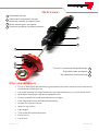
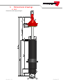
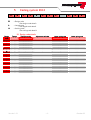
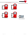
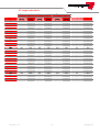
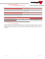
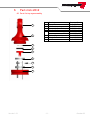
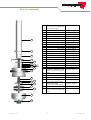
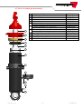
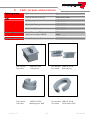
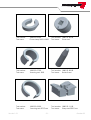
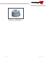
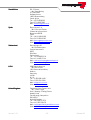
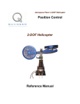
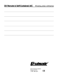
2612 Features
1 Detachable top eye
2 Adjustment integrated in top eye
Bump and rebound: 8 positions each
3 Quick release upper springseat
4 Induction hardened, chromed pistonrod
7
6
5
4
3
2
1
Formula 1 proven seal and guide design 5
Adjustable lower springseat 6
Hard anodized aluminium body 7
Other unique features
Forces in both bump and rebound are generated by the piston area and are not effected by
displacement of the piston rod
Low speed damping in 2 stages (bleed holes and valve loaded ports), no use of needle valves
Wide adjustment range in equal and repeatable clicks
Factory assembled and calibrated adjustment cartridges
Fully independent bump and rebound adjustability
No need for external reservoir
Works in any position
Light weight
Tailor made and individually tested
Easily service
Low friction
Version 1.2
October 08
Contents
1
GENERAL INFORMATION ................................................................
................................................................................................
.........................................................................................
......................................................... 2
1.1
1.2
1.3
1.4
2
DAMPER TYPE .....................................................................................................................................................2
LOW SPEED DAMPING..........................................................................................................................................2
HIGH SPEED DAMPING .........................................................................................................................................2
UNIQUE FEATURES ..............................................................................................................................................2
WORKING PRINCIPALS OF
OF 2612 ................................................................
................................................................................................
.............................................................................
............................................. 3
2.1
2.2
LOW SPEED DAMPING..........................................................................................................................................3
HIGH SPEED DAMPING .........................................................................................................................................3
3
ADJUSTMENT MECHANISM................................
MECHANISM................................................................
................................................................................................
......................................................................................
...................................................... 4
4
DIMENSIONAL DRAWINGS ................................................................
................................................................................................
......................................................................................
...................................................... 5
4.1
5
2612 ...................................................................................................................................................................5
CODING SYSTEM 2612 ................................................................
................................................................................................
..............................................................................................
.............................................................. 6
5.1
5.2
5.3
6
DESIGN CODE DETAILS ........................................................................................................................................6
LENGTH CODE DETAILS........................................................................................................................................9
VALVING CODE DETAILS....................................................................................................................................10
PARTS LISTS 2612 ................................................................
................................................................................................
................................................................................................
..................................................................
.................................. 11
6.1
6.2
6.3
6.4
7
PARTS LIST TOP EYE ASSEMBLY........................................................................................................................11
PARTS LIST ROD ASSEMBLY ..............................................................................................................................12
PARTS LIST BODY & GUIDE ASSEMBLY ..............................................................................................................13
PARTS LIST ACCESSORIES ................................................................................................................................14
SERVICE MANUAL................................
MANUAL................................................................
................................................................................................
................................................................................................
...................................................................
................................... 15
7.1
7.2
7.3
7.4
7.5
INTRODUCTION .................................................................................................................................................15
REBUILD DATA ..................................................................................................................................................15
DISMANTLING ...................................................................................................................................................16
ASSEMBLY.........................................................................................................................................................17
GAS FILLING .....................................................................................................................................................18
8
TESTING ................................................................
................................................................................................
................................................................................................
..................................................................................
.................................................. 19
9
TOOLS, TORQUES AND PRESSURES
PRESSURES................................
RESSURES................................................................
................................................................................................
.......................................................................
....................................... 20
10
DISTRIBUTION RACE DAMPERS
DAMPERS ................................................................
................................................................................................
........................................................................
........................................ 23
Revision history
Version 1.2: October 2008©
Version 1.2
-1-
October 08
1
General information
The 2612 series is based on the proven technology of our 2812 MKII and 2822 MKII series racing
dampers. The 2612 series has been developed to meet the highest quality standards. Be sure that you
treat this product for what it is: a complex hydraulic device, containing precision parts and built with the
most care. Be sure that the damper is not opened by unauthorized mechanics and note that the damper
is under high gas pressure.
1.1 Damper type
The 2612 series is a mono-tube high pressure gas shock absorber. Specifically designed for competition
purposes, it is fully adjustable while fitted on the car. It contains one adjuster in bump (compression)
and one in rebound (extension). Its precision adjustment mechanism allows the maximum control
possible over the generated damping forces.
1.2 Low speed damping
On modern racing cars precise control over the damping forces at low speeds is very important. This in
turn means that very small flows of oil have to be controlled. In many racing damper designs, a needle
valve is used to try to achieve this. Such a simple mechanism has many drawbacks. For Koni,
repeatability, consistency and ease of use are a must for every racing damper. To achieve this, the 2612
series uses superior and advanced adjustment cartridges that control the opening and closing of valve
loaded ports. These two cartridges are contained in the main piston, one for bump and one for rebound.
They operate totally independent of each other. For both bump and rebound 8 adjustment positions are
available, generating a total of 64 predefined damping curves. Distinct stops (clicks) assure that each
port can only be either open or close.
Thus total repeatability of performance is engineered into the damper and the need for calibration on a
damper dyno is eliminated.
A unique feature is that the low speed damping is created through 2 stages, the first by predefined bleed
holes and the other one by ports.
1.3 High speed damping
With high piston velocities, such as those correlated with rough sections of pavement, the high speed
damping becomes important. The suspension needs to be able to move instead of becoming solid due to
too much damping. A main valve enclosed in the piston, controls the high speed damping. It allows the
damper to have a blow-off force.
1.4 Unique features
Also unique to both low as well as high speed damping is that the bump and rebound forces are
generated by the piston area and not by rod displacement at all. This creates a very precise control over
the damping forces and very little phase lag (hysteresis) due to the lower hydraulic pressures. Besides,
it makes a separate reservoir to accommodate the bump adjuster superfluous, and installation simple,
lightweight and clean.
Version 1.2.1
-2-
October 08
2
Working principals of 2612
When the piston rod is pushed into the body of the damper, it displaces its own volume in oil. To make
this possible the lower part of the damper is filled with nitrogen. This nitrogen can be compressed and is
separated from the oil by a floating piston. When the piston rod is pushed into the body of the damper its
volume will push down the floating piston a little bit and is thereby creating more space in the cylinder to
accept the intruding piston rod. While moving the piston through the damper, oil will flow through the
separate bump and rebound cartridges. In these cartridges the oil will flow through valve loaded ports.
When the oil flows through it creates a pressure drop over the piston, which gives a damping force on
the piston rod. The use of separate cartridges is a unique and patented Koni feature. The damper forces
are generated by the amount of oil flowing through the piston and not the much smaller amount of oil
displaced by the piston rod only. When the oil can not flow away quickly enough through the low speed
cartridges the pressure difference over the piston increases that much the mainvalve would be opened.
The damping characteristic can be divided in two velocity ranges. The low speed range from 0 up to 0,2
m/s and the high speed range from 0,2 m/s and higher, depending on valving and click setting of the
damper.
2.1 Low speed damping
The valves in the bump and rebound cartridge control the low speed damping. So when the damper
would be compressed, pressure will build up over the piston and the valves in the bump cartridge will
open. The same counts when the damper is being extended for the rebound cartridge. The valves are
thin steel plates, which will bend due to the oil pressure. The bump and rebound cartridges can be
exchanged easily if a different range of bump and / or rebound damping forces is needed.
bump stroke
rebound stroke
mainvalve
piston
rebound cartridge
bump cartridge
2.2 High speed damping
The main valve controls the pressure when the flow over the piston becomes to high to be handled by
the low speed cartridges only. The oil will flow through both the cartridges and the mainvalve to create
either a digressive, linear or progressive characteristic. Because the pressure difference between the
area under and above the piston, the oil will flow through the mainvalve until the difference is small
enough to be handled by the low speed cartridges only. The main valve can be exchanged if a different
range of bump and / or rebound high speed damping forces is needed.
Version 1.2.1
-3-
October 08
3
Adjustment mechanism
Rotating the adjustment discs, located in the window of the top eye, adjusts the damping. You only need
a steel pin adjustment tool of 1.5 mm (0.06”) diameter. The adjusters are marked with letters that are
visible on the alloy top eye, with a ‘B’ for bump and an ‘R’ for rebound next to the corresponding disc. The
bump and rebound discs are also recognizable at their color. The bump-disc is colored black and the
rebound-disc is colored red. Rotate the discs according to the markings on the top eye.
The adjusters have 8 distinct stops (clicks), each of which marks an adjustment position. There are a
total of 8 adjustment positions from minimum to maximum adjustment. The minimum position is
referred to as position 1 and the maximum adjustment position as position 8. The adjusters have a
positive stop at the minimum and maximum position.
Never use excessive force wh
while adjusting cause damage may result.
adjustment window
Version 1.2.1
-4-
October 08
4
Dimensional drawings
4.1 2612
dimensions with topeye design 4
Version 1.2.1
-5-
October 08
5
2
Coding system 2612
6
1
D
= Design code
L
= Length code
2
D
L
L
L
V
V
V
See design code details
See length code details
V
= Valving code
See valving code details
5.1 Design code details
Design
code
A
B
C
G
H
I
N
O
P
R
S
T
U
V
W
Y
Z
Topeye
Topeye bearing
Adjustment window
Upper spring seat
Lower spring seat
Design 1
Design 2
Design 3
Design 1
Design 2
Design 3
Design 5
Design 4
Design 4
Design 5
Design 6
Design 6
ID 7/16"
ID 7/16"
ID 7/16"
ID 7/16"
ID 7/16"
ID 7/16"
ID 1/2"
ID 7/16"
ID 7/16"
ID 1/2"
ID 1/2"
ID 1/2"
0˚
0˚
0˚
0˚
0˚
0˚
0˚
90˚
90˚
0˚
90˚
90˚
2"
2"
2"
1.88"
1.88"
1.88"
1.88"
2"
1.88"
1.88"
2"
2"
2"
1.88"
2"
2"
2"
1.88"
1.88"
1.88"
1.88"
2"
2"
1.88"
1.88"
1.88"
2"
2"
2"
1.88"
Version 1.2.1
-6-
October 08
5.1.1
Top eye designs
Topeye design 1
Topeye design 2
Topeye design 3
Topeye design 4
Steel top for welding purposes
part no. 71-51-01-085-0
(must be ordered separately)
Version 1.2.1
-7-
October 08
Bump
rubber
Spring seat
Bearing
Top eye
5.1.2
Design code part numbers
design 1
71 52 07 081 0
design 2
71 52 07 082 0
design 3
71 52 07 087 0
design 4
71 52 07 084 0
design 5
71 52 07 046 0
design 6
71 52 07 047 0
1/2” (use with top eye design 5 and 6)
1425 50 00 29
7/16” (use with top eye design 1, 2, 3, 4 and bottom)
1425 50 00 14
Upper 1.88”
71 29 01 080 0
Upper 2”
71 29 01 060 0
Lower 1.88”
71 29 11 124 0
Lower 2”
71 29 11 123 0
OD 46.5 mm (use with 2” upper spring seat)
71 34 80 000 0
OD 43.5 mm (use with 1.88” upper spring seat)
71 34 95 000 0
5.1.3
2612 001 950
2612 004 VVV
2612 005 VVV
Version 1.2.1
Special designs
Dallara F305, F306 and F307 front / rear
Lola F3/06 front
Lola F3/06 rear
-8-
without topeye
including topeye
including topeye
October 08
5.2 Length code details
Length code
224
229
234
239
244
249
254
259
264
269
274
279
284
289
294
299
304
309
314
319
324
329
334
339
344
349
354
359
364
369
374
Topeye design 1
Lmax
Lmin
[mm]
[mm]
224
195
229
200
234
200
239
205
244
205
249
210
254
210
259
215
264
215
269
220
274
220
279
225
284
225
289
230
294
230
299
235
304
235
309
240
314
240
319
245
324
245
329
250
334
250
339
255
344
255
349
260
354
260
359
265
364
265
369
270
374
270
Version 1.2.1
Topeye design 2
Lmax
Lmin
[mm]
[mm]
229
200
234
200
239
205
244
205
249
210
254
210
259
215
264
215
269
220
274
220
279
225
284
225
289
230
294
230
299
235
304
235
309
240
314
240
319
245
324
245
329
250
334
250
339
255
344
255
349
260
354
260
359
265
364
265
369
270
374
270
379
275
-9-
Topeye design 3
Lmax
Lmin
[mm]
[mm]
234
200
239
205
244
205
249
210
254
210
259
215
264
215
269
220
274
220
279
225
284
225
289
230
294
230
299
235
304
235
309
240
314
240
319
245
324
245
329
250
334
250
339
255
344
255
349
260
354
260
359
265
364
265
369
270
374
270
379
275
384
275
Stroke [mm]
Lbody [mm]
29
29
34
34
39
39
44
44
49
49
54
54
59
59
64
64
69
69
74
74
79
79
84
84
89
89
94
94
99
99
104
149
154
154
159
159
164
164
169
169
174
174
179
179
184
184
189
189
194
194
199
199
204
204
209
209
214
214
219
219
224
224
October 08
5.3 Valving code details
5.3.1
Standard cartridge combinations
Bump valve code
3
5
7
Bump cartridge
71 60 21 030 9
71 60 21 050 9
71 60 21 070 9
Rebound valve code
3
5
7
Rebound cartridge
71 60 22 003 9
71 60 22 005 9
71 60 22 007 9
633
653
Possible standard
standard valvings
635
655
675
657
677
For more detailed information and forces, please request the valving list.
5.3.2 Special valvings
KONI has developed a lot of specific characteristics for its customers over the past years, if you need
anything different from above mentioned standard cartridge combinations, please request our
valvinglist or contact KONI to discuss your requests. We would be pleased to help you with your specific
application.
Version 1.2.1
- 10 -
October 08
6
Parts lists 2612
6.1 Parts list top eye assembly
1
2
1
2
3
4
5
6
7
8
9
Bearing
Topeye
Anti-rattle spring
Bump adjustment disc
Rebound adjustment disc
Thrust washer
3.0 mm
3.5 mm
Collets (2 per unit)
Wedge collar
Lock nut
See page 7
See page 7
71 05 51 018 0
71 09 00 148 0
71 09 00 149 0
71 10 07 270 0
71 10 07 343 0
71 10 07 271 0
71 10 07 272 0
71 51 05 029 0
6.2
3
4
5
6
7
8
9
Version 1.2.1
- 11 -
October 08
Parts list rod assembly
1
Piston rod
2826 01 *** 16
(*** = refer to rebuild data
for required length)
2
3
4
5
1
6
2
7
3
8
4
5
6
7
9
10
11
71 36 01 144 0
71 05 01 219 0
71 10 07 422 0
71 05 04 039 0
71 05 01 267 0
71 05 01 264 0
71 05 01 265 0
71 05 01 266 0
71 05 04 047 0
71 05 04 041 0
71 05 11 004 0
71 05 11 002 0
71 05 11 003 0
71 05 04 068 0
71 12 00 134 0
71 12 02 059 0
71 41 22 *** 0
(*** = piston rod length –1
mm)
13
14
15
16
Tube quad-ring
Thrust washer
Rod quad-ring
Rebound cartridge
15
17
Bump cartridge
17
18
19
12
14
8
9
10
11
12
Rebound-spacer
Washer
Abutment disc
Rebound valve seat
17 x 12.1 x 2
Main valve
33.4 x 0.2
33.4 x 0.3
33.4 x 0.4
33.4 x 0.5
Inner preload washer
0.5
0.7
Preload disc
26.5 x 0.3
26.5 x 0.4
26.5 x 0.5
Outer preload washer
Piston
Piston seal
Rebound adjuster tube
13
16
1604 73 00 08
71 05 05 019 0
1604 73 00 06
71 60 22 *** 0
(*** = refer to valvinglist)
71 60 21 *** 0
(*** = refer to valvinglist)
Piston locking nut
Bump adjuster rod
71 25 00 163 0
71 41 16 *** 0
(*** = piston rod length +44
mm)
18
19
Version 1.2.1
- 12 -
October 08
6.3 Parts list body & guide assembly
1
2
3
4
5
6
1
2
3
Spring seat circlip
Upper spring seat
Bump rubber
Bump cap
Guide circlip
Guide assembly
Guide O-ring (30 x 2.5)
7 Cylinder full thread (incl. 7/16” bearing)
Cylinder without threading (incl. 5/16” bearing)
8 Lower spring seat
Lower spring seat locking bolt (M5)
9 Floating piston
10 Floating piston O-ring
11 Gas filling bolt (hexagonal socket screw)
12 Dowty seal
1038 22 00 40
See page 7
See page 7
71 25 02 058 0
15 33 09 025 0
71 22 20 384 9
1601 73 13 85
2612 52 07 02
2612 52 07 01
See page 7
71 07 06 012 0
71 12 11 059 0
1601 73 12 29
1035 62 06 20
1611 04 50 70
4
5
6
7
8
9
10
11
12
Version 1.2.1
- 13 -
October 08
6.4 Parts list accessories
1
2
3
4
Topeye + 28.5 mm (incl. 7/16” bearing)
Topeye + 35.0 mm (incl. 7/16” bearing)
Topeye + 48.5 mm (incl. 7/16” bearing)
Topeye F3 Style (incl. 5/16” bearing)
Lock nut
Upper spring seat (for 36 mm ID springs)
Upper spring seat locking bolt (M4)
Lower spring seat (for 36 mm ID springs)
2812 52 07 26
2812 52 07 28
2812 52 07 27
2812 52 07 68
71 52 07 069 0
71 29 01 074 0
71 07 06 013 0
71 25 02 055 0
Always use top eyes
eyes as short as possible
5
71 52 11 026 0
Adapter bush (ø 8 mm)
4
5
1
Version 1.2.1
2
3
- 14 -
October 08
7
Service manual
7.1 Introduction
Revalving a 2612 type damper is a relatively straightforward process, but should never be taken lightly.
It is a very delicate hydraulic-mechanical piece of equipment with a vital control function and should
always be treated as such. Keep the following points in mind before you start dismantling the damper.
This damper is charged with high-pressure nitrogen gas. Please take appropriate precautions
when handling or opening.
Shock absorbers and dirt do not get along at all. Dirt in this case is anything that is not meant to
be inside the housing; sand, metal bits, fluff from cleaning rags, remains of O-rings etc. So make
sure the work environment, tools and all damper components are as clean as possible.
Both dimensions and form of all parts are machined to tight tolerances, and should therefore be
handled with care. Scratches or deformation of critical parts could cause loss of damping
performance.
Always use aluminium clamping plates when putting the damper or its components in a vice.
When the damper is taken apart, make sure the O-rings are replaced and lubricated before
putting the damper back together.
7.2 Rebuild data
Length
code
224
229
234
239
244
249
254
259
264
269
274
279
284
289
294
299
304
309
314
319
324
329
334
339
344
349
354
359
364
369
374
Version 1.2.1
Pistonrod
length [mm]
[mm]
76
76
81
81
86
86
91
91
96
96
101
101
106
106
111
111
116
116
121
121
126
126
131
131
136
136
141
141
146
146
151
Rebound adjuster tube
length [mm]
75
75
80
80
85
85
90
90
95
95
100
100
105
105
110
110
115
115
120
120
125
125
130
130
135
135
140
140
145
145
150
- 15 -
Bump adjuster rod
length [mm]
120
120
125
125
130
130
135
135
140
140
145
145
150
150
155
155
160
160
165
165
170
170
175
175
180
180
185
185
190
190
195
Floating piston
height [mm]
71
71
75
75
79
79
84
84
88
88
92
92
97
97
101
101
105
105
109
109
114
114
118
118
122
122
126
126
131
131
135
October 08
7.3 Dismantling
Clean the exterior thoroughly. Set both adjustments to minimum position.
7.3.1 Top eye
Make sure all the tension is off the main spring by lowering the spring seat on the body.
The circlip on the top attachment can now be removed. Take off the upper spring seat and the spring
itself.
Carefully put the top mount in a vice. Use a Pin-spanner (size 40/42, order n° 1880-22-16-00) to slacken
the circular lock nut.
Do not remove the top mount yet.
Take the damper out off the vice. Hold the lock nut in one hand, the top mount pointing upwards. With
the other hand remove the top mount. Keep all parts, especially the adjuster parts in order. Notice the
thickness of the thrust washer (n° 4, page 11), it’s 3.0 or 3.5 mm. It is used to keep the overall length
within a ± 0.5-mm tolerance. Remove the wedge collar and collets (if needed tap on the wedge collar
with a soft-faced hammer)
7.3.2 Shock absorber unit
Slowly release the gas pressure by turning the hexagon socket bolt beside the bottom eye; use a 2.5-mm
Allen key.
Remove the bump cap with a dull screwdriver and a hammer. Put the damper with the bottom eye
upright in a vice. Push the guide down a little. If this proves hard to do, check all nitrogen has been
removed. Gently tap down the guide with a large drift and a soft faced hammer till you are able to pry
out the guide circlip. Gently tap the complete piston assembly out of the body till the guides O-ring
becomes visible, after this you could push the guide and piston assembly out of the cylinder.
7.3.3 Piston assembly
Pull the bump adjuster rod out of the rod assembly and inspect to see if it is free from burrs.
Use tool n° 1880-22-05-00 to clamp the piston. Loosen the piston lock nut with a hexagon nut 32 mm.
Remove piston nut, bump and rebound low speed cartridges and rebound adjuster tube. Notice the small
quad-ring in the bottom of the tube.
If the main valve needs changing, the piston can now be removed. Use tool n° 1880-22-06-00 to loosen
the piston. Use tool n° 1880-22-02-00 to clamp the rod in a vice. Make sure to tighten it correctly so the
rod won’t damage.
Before removing the guide check the piston side of the piston rod for irregularity. This could cause
damage for the guide bush and other internal parts of the guide.
Version 1.2.1
- 16 -
October 08
7.4 Assembly
Inspect all parts, seals and O-rings for damage. Replace as needed.
7.4.1 Piston assembly
If the guide has been removed, grease the seal before assembling. Use tool n° 1880-22-08-00 to make
sure the guide seal would not be damaged. Before installing the piston, the following parts must be
installed over the piston (refer to parts list rod assembly)
Outer preload washer
Preload disc
Inner preload washer
Main valve(s)
Rebound valve seat
Abutment disc
Rebound disc
Tighten the piston with a torque of 30 lbs.-ft or 40 Nm with the piston tool n° 1880-22-06-00. Lubricate
the rebound adjuster tube and quad-ring before sliding it into the piston rod.
Install respectively rebound and bump low speed cartridge. Ensure a proper engagement of the rebound
cartridge with the adjuster tube.
Lubricate the end of the bump adjuster rod and slide it through the cartridges until it fits onto the bump
cartridge.
Use tool n° 1880-22-05-00 to clamp the piston.
Fit the piston lock nut and tighten it with a torque of 22 lbs.-ft or 30 Nm. Use a hexagon nut 32 mm.
7.4.2 Shock absorber unit
Check the floating piston height according to build sheet. The height “H” is measured from the top of the
cylinder to the bottom of the floating piston. Make sure this is done correctly. For exact placement of the
floating piston use our tool 1884-00-06-00.
Fill the body with oil up to the circlip groove. Make sure the gas filling bolt is not tightened. Gently push
the rod assembly into the housing till the guide is under the circlip grooves position. Be sure not moving
the piston rod when the guide is fitted, cause this would change your floating piston height. Fit the circlip
and check that it fits snugly into its groove. Tighten the gas filling bolt.
7.4.3 Top eye
Install the bump cap, bump stop and / or travel limiter. Install the top eye components in reverse order
of disassembly and torque the top eye locknut with 55 lbs -ft or 75 Nm. Use Pin-spanner (size 40/42,
order n° 1880-22-16-00) to tighten. For tightening the locknut you could use our topeye mould (n°
1880-22-01-00) to save the topeye.
Version 1.2.1
- 17 -
October 08
7.5 Gas filling
General notice: Replace dowty-seal of the gas filling bolt every time and pressurise the damper with
nitrogen only!
Place the damper into gas filling tool n° 1880-00-10-50. Make sure the hexagon key engages with the
gas filling bolt and tighten it.
Adjust the filling pressure according to the data on this page. Pressurise the tool and slowly undo the gas
filling bolt for a full turn. The piston rod should be pressed fully outwards.
Leave the pressure on for 10 or more seconds and close the filling bolt.
Release the pressure from the gas filling tool and remove the damper. Make sure that the bolt is
tightened; check this with a 2.5 mm Allen key, if you aren’t sure about it.
To check if the floating piston isn’t too high, push the bump adjuster at the top of the damper inside.
Little resistance must be appreciable.
Finally check carefully for leaks, especially at the dowty-seal of the gas filling bolt, as leakages here tend
to be very small and hard to spot.
Important: The gas pressure is important for a proper function of the damper. Some race engineers try
to lower the gas pressure without always realising the risk involved. If the gas pressure is too low, air
will be drawn into the damper. This will have a negative effect on its performance. To calculate the
minimum required gas pressure, the highest bump damper force ever occurring is taken.
Apply pressure on for at least 10
seconds to make sure the
nitrogen chamber is filled
7.5.1 Minimum Gas Pressure Calculation.
The minimum filling of the gas in the damper is simply calculated by dividing the maximum bump force
by the piston area / rod area.
General notice: Make sure that the outcome of the calculation is multiplied with a factor of 1.1. This is for
safety because the gas pressure differs when the temperature changes.
p min =
Fmax in
* (safety factor of) 10% (1.1)
Apiston − Arod
With:
Apiston
Arod
Pmin
Fmax in
:
:
:
:
Piston area [m2]
Rod area [m2]
Minimal pressure below floating piston [N/m2]
Maximal damper force Inward [N]
The piston area minus the rod area of the 2612 damper is 0.869 *10-3 m2. The maximal bump force could
be known from gathered data. Multiply the outcome with a factor of 1.1 and the minimum pressure is
there.
Version 1.2.1
- 18 -
October 08
8
Testing
Make sure everything is tightened at the specific torque and both adjusters are in beginning position. Do
this by turning them counter clockwise.
Never use excessive force while the adjustments are done as damage may result.
Before testing take the necessary precautions involving safety for your self and the surrounding people.
Put on safety glasses, right clothing and safety shoes.
After all precautions are made testing can be started.
Test the dampers in both minimum and maximum position.
The forces the different valvings should produce can be found in the valving list.
Version 1.2.1
- 19 -
October 08
9
Tools, torques and pressures
Tightening torques
Tools
Gas filling pressure
Gas filling tool
Oil type
Piston to piston rod
Piston nut to piston
Top eye lock nut to top eye
Torque wrench with fitting for tools
Circlip top eye lock nut tool
Guide fitting tool
Piston rod clamping tool
Piston fitting tool
Piston clamp (36 mm)
Floating piston height setting tool
Bump forces up to 2000 N
Bump forces as from 2000 N
For standard or F3 type bottom
Fuchs 5045 (1L)
30 lbs.-ft or 40 Nm
22 lbs.-ft or 30 Nm
55 lbs.-ft or 75 Nm
1851 16 55 71
1880 22 16 00
1880 22 08 00
1880 22 02 00 (order 2 pc.)
1880 22 06 00
1880 22 05 00
1884 00 06 00
15 bar
20 bar
1880 00 10 50
1006 01 01 18
Tool number:
Tool name:
1880-22-01-00
Top eye tool
Tool number: 1880-22-02-00
Tool name:
Rod clamp(s)
Tool number:
Tool name:
1880-22-03-00
Mounting tool 2822
Tool number: 1880-22-04-00
Tool name:
Piston clamp 2812
Version 1.2.1
- 20 -
October 08
Tool number:
Tool name:
1880-22-05-00
Piston clamp 2612 & 2822
Tool number: 1880-22-06-00
Tool name:
Piston tool
Tool number:
Tool name:
1880-22-07-00
Inserting tool 2822
Tool number: 1880-22-08-00
Tool name:
Guide fit tool
Tool number:
Tool name:
1880-22-09-00
Inserting tool GP2 Front
Tool number: 1880-22-11-00
Tool name:
Clamp tool GP2 Front
Version 1.2.1
- 21 -
October 08
Tool number:
1880-22-13-00
Tool name: Mounting tool GP2 Front
Version 1.2.1
- 22 -
October 08
10
Distribution Race Dampers
The KONI Race dampers, with their specific technology, are represented and put to market by specially
KONI trained and officially appointed distributors in the following countries world-wide.
Australia
Toperformance Products Co.
Mr. Barry Brookes
8, Trade Place
Vermont
Victoria 3133
Australia
Tel.: +61 (0)3 987 31722
Fax: +61 (0)3 987 42200
Mail :[email protected]
Web : www.toperformance.com.au
Belgium
R.TEC
Mr. Fabio Lazzerini
Zoning d’Heppignies II
6220
Heppignies
Belgium
Tel.: +32 (0)71 377 707
Fax: +32 (0)71 377 708
Mail: [email protected]
France
KONI France S.A.R.L.
Mr. Didier Maria
B.P. No. 9
Route Nationale 7
06271
Villeneuve-Loubet
France
Tel.: +33 49 3206816
Fax: +33 49 3225050
Mail: [email protected]
Web : www.koni.fr
Germany
KONI BV Vertriebsbüro Deutschland
Mr. Ralf Hommrich
Rheinstraße 96
56235
Ransbach-Baumbach
Germany
Tel. +49 (0)262360226
Fax : +49 (0)262360233
Mail : [email protected]
Web : www.koni.de
Version 1.2.1
- 23 -
October 08
Italy
Weiss S.p.A.
Mr. Alberto Weiss
Via dei Crollalanza 4
20143
Milano
Italy
Tel.: +39 02 8358141
Fax: +39 02 8375576
Mail: [email protected]
Web : www.weiss.it
Japan
Far East Trading Co. Ltd.
Mr. Gunji Satoshi
4-30-11, Chitosedai
Tokyo 157-0071
Japan
Tel.: +81 3 54902551
Fax: +81 3 54909483
Mail: [email protected]
Web : www.fet-japan.co.jp/
The Netherlands
KONI BV
Mr. Frits Altorf
Postbus 1014
3260 AA Oud Beijerland
The Netherlands
Tel.: +31 (0)186 635500
Fax: +31 (0)186 635612
Mail: [email protected]
Web : www.koni.com
The Netherlands
Verbaas Preparations
Mr. Frans Verbaas
Koninginneweg 87
3261 CB Oud Beijerland
The Netherlands
Tel.: +31 (0)186 612397
Fax: +31 (0)186 619760
Mail: [email protected]
Web : www.verbaaspreparations.nl
New Zealand
George Stock & Company Ltd.
Mr. Russell Leach
P.O. Box 62-102
8 TE Apunga Place
Mount Wellington
Auckland
New Zealand
Tel.: +64 9 270 7220
Fax: +64 9 270 7221
Mail: [email protected]
Web : www.georgestock.co.nz
Version 1.2.1
- 24 -
October 08
South Africa
D & S Shocks
Mr. Steve Hurley
P.O. Box 2863
Halfway house
1685 Johannesburg
South Africa
Tel.: +2712 6538393
Fax: +2711 8057999
Mail: [email protected]
Spain
Beyco Union S.A.
Mr. Félix Jose Pastor
Ciudad de la Asuncion 4
Barcelona 08030
Spain
Tel.: +34 93 360 06 00
Fax: +34 93 360 06 02
Mail: [email protected]
Web: www.beycounion.com
Switzerland
Derendinger AG
Mr. Rüdi Mosimann
Industriestrasse 8
8305
Dietlikon
Switzerland
Tel.: +41 44 805 23 16
Fax: +41 44 805 21 44
Mail: [email protected]
Web: www.derendinger.ch
U.S.A.
KONI North America
Mr. Lee Grimes
1961 International Way
Hebron
Kentucky
41048
U.S.A.
Tel.: +1 859 586 4100
Fax: +1 859 334 3340
Mail: [email protected]
Web : www.koni-na.com
United Kingdom
Camberley Auto Factors Ltd.
Mr. Trevor Leigh
Unit 2, Hawley Trading Estate
Hawley Lane
Farnborough, Hampshire
GU14 8EH
United Kingdom
Tel.: +44 1252 517272
Fax: +44 1252 522470
Mail: [email protected]
Web: www.camberleyautofactors.com
Version 1.2.1
- 25 -
October 08
Special conditions apply to registered OEM racing car manufacturers.
Contact KONI-Holland for more information.
KONI B.V, P.O. BOX 1014, 3260 AA OUD-BEYERLAND, HOLLAND
TEL +31 (0) 186 635500
FAX +31 (0) 186 635612
Email: [email protected]
www.koni.com