1
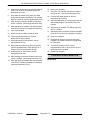
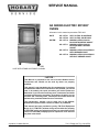
SERVICE MANUAL
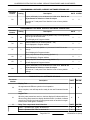
KA SERIES ELECTRIC ROTARY
OVENS
Information in this manual superceedes TSB 1406.
KA7E
KA7EM
ML-137701
ML-137709
ML-137710
ML-137711
ML-137713
ML-137714
SELF-CLEAN, GLASS BACK
SELF-CLEAN, SOLID BACK
MANUAL-CLEAN, GLASS
BACK WITH GREASE ASSIST
MANUAL-CLEAN, GLASS
BACK WITHOUT GREASE
ASSIST
MANUAL-CLEAN, SOLID BACK
WITH GREASE ASSIST
MANUAL-CLEAN, SOLID BACK
WITHOUT GREASE ASSIST
KA7E WITH STAND ACCESSORY SHOWN
- NOTICE This Manual is prepared for the use of trained Hobart Service
Technicians and should not be used by those not properly
qualified.
This manual is not intended to be all encompassing. If you have
not attended a Hobart Service School for this product, you should
read, in its entirety, the repair procedure you wish to perform to
determine if you have the necessary tools, instruments and skills
required to perform the procedure. Procedures for which you do
not have the necessary tools, instruments and skills should be
performed by a trained Hobart Service Technician.
The reproduction, transfer, sale or other use of this Manual,
without the express written consent of Hobart, is prohibited.
This manual has been provided to you by ITW Food Equipment
Group LLC ("ITW FEG") without charge and remains the property
of ITW FEG, and by accepting this manual you agree that you will
return it to ITW FEG promptly upon its request for such return at
any time in the future.
A product of Hobart Service
701 S. Ridge Ave Troy, OH 45374
F25294 Rev. A (0412)
KA SERIES ELECTRIC ROTARY OVENS
TABLE OF CONTENTS
GENERAL . . . . . . . . . . . . . . . . . . . . . . . . . . . . . . . . . . . . . . . . . . . . . . . . . . . . . . . . . . . . . . . . . . . . . . . . . . . . . . . . . . . . . . . . . . . . . . . . . .
REFERENCE INFORMATION . . . . . . . . . . . . . . . . . . . . . . . . . . . . . . . . . . . . . . . . . . . . . . . . . . . . . . . . . . . . . . . . . . . . . . . . . .
TSB'S & TSI'S . . . . . . . . . . . . . . . . . . . . . . . . . . . . . . . . . . . . . . . . . . . . . . . . . . . . . . . . . . . . . . . . . . . . . . . . . . . . . . . . . . . . . .
INSTRUCTIONS & SPECIFICATIONS . . . . . . . . . . . . . . . . . . . . . . . . . . . . . . . . . . . . . . . . . . . . . . . . . . . . . . . . . . . . . .
INTRODUCTION . . . . . . . . . . . . . . . . . . . . . . . . . . . . . . . . . . . . . . . . . . . . . . . . . . . . . . . . . . . . . . . . . . . . . . . . . . . . . . . . . . . . . . .
ELECTRICAL SPECIFICATIONS . . . . . . . . . . . . . . . . . . . . . . . . . . . . . . . . . . . . . . . . . . . . . . . . . . . . . . . . . . . . . . . . . . . . . . .
WATER SUPPLY REQUIREMENTS (KA7E ONLY) . . . . . . . . . . . . . . . . . . . . . . . . . . . . . . . . . . . . . . . . . . . . . . . . . . . . . .
TOOLS . . . . . . . . . . . . . . . . . . . . . . . . . . . . . . . . . . . . . . . . . . . . . . . . . . . . . . . . . . . . . . . . . . . . . . . . . . . . . . . . . . . . . . . . . . . . . . . . .
ACCESSORY STAND INSTRUCTIONS . . . . . . . . . . . . . . . . . . . . . . . . . . . . . . . . . . . . . . . . . . . . . . . . . . . . . . . . . . . . . . . . .
KA7E SELF-CLEAN (ML-137701, ML-137709) . . . . . . . . . . . . . . . . . . . . . . . . . . . . . . . . . . . . . . . . . . . . . . . . . . . . . .
KA7EM WITH GREASE ASSIST (ML-137710, ML-137713) . . . . . . . . . . . . . . . . . . . . . . . . . . . . . . . . . . . . . . . . . .
KA7EM WITHOUT GREASE ASSIST (ML-137711, ML-137714) . . . . . . . . . . . . . . . . . . . . . . . . . . . . . . . . . . . . .
TETHER BRACKET AND OVEN MOUNTING TO STAND (KA7E, KA7EM) . . . . . . . . . . . . . . . . . . . . . . . . . . .
REMOVAL AND REPLACEMENT OF PARTS . . . . . . . . . . . . . . . . . . . . . . . . . . . . . . . . . . . . . . . . . . . . . . . . . . . . . . . . . . . . . .
COVERS . . . . . . . . . . . . . . . . . . . . . . . . . . . . . . . . . . . . . . . . . . . . . . . . . . . . . . . . . . . . . . . . . . . . . . . . . . . . . . . . . . . . . . . . . . . . . .
PUMP COVER . . . . . . . . . . . . . . . . . . . . . . . . . . . . . . . . . . . . . . . . . . . . . . . . . . . . . . . . . . . . . . . . . . . . . . . . . . . . . . . . . . . .
RIGHT SIDE COVER . . . . . . . . . . . . . . . . . . . . . . . . . . . . . . . . . . . . . . . . . . . . . . . . . . . . . . . . . . . . . . . . . . . . . . . . . . . . . .
LEFT SIDE COVER . . . . . . . . . . . . . . . . . . . . . . . . . . . . . . . . . . . . . . . . . . . . . . . . . . . . . . . . . . . . . . . . . . . . . . . . . . . . . . .
TOP COVER (CONTROL PANEL) . . . . . . . . . . . . . . . . . . . . . . . . . . . . . . . . . . . . . . . . . . . . . . . . . . . . . . . . . . . . . . . . .
TOP COVER . . . . . . . . . . . . . . . . . . . . . . . . . . . . . . . . . . . . . . . . . . . . . . . . . . . . . . . . . . . . . . . . . . . . . . . . . . . . . . . . . . . . . .
FAN COVER . . . . . . . . . . . . . . . . . . . . . . . . . . . . . . . . . . . . . . . . . . . . . . . . . . . . . . . . . . . . . . . . . . . . . . . . . . . . . . . . . . . . . .
DOOR . . . . . . . . . . . . . . . . . . . . . . . . . . . . . . . . . . . . . . . . . . . . . . . . . . . . . . . . . . . . . . . . . . . . . . . . . . . . . . . . . . . . . . . . . . . . . . . .
DOOR ADJUSTMENT . . . . . . . . . . . . . . . . . . . . . . . . . . . . . . . . . . . . . . . . . . . . . . . . . . . . . . . . . . . . . . . . . . . . . . . . . . . . .
DOOR SWITCH ADJUSTMENT (KA7E ONLY; IF REQUIRED) . . . . . . . . . . . . . . . . . . . . . . . . . . . . . . . . . . . . .
DOOR SWITCH MAGNET (KA7E ONLY) . . . . . . . . . . . . . . . . . . . . . . . . . . . . . . . . . . . . . . . . . . . . . . . . . . . . . . . . . . . . . .
OUTER DOOR GLASS . . . . . . . . . . . . . . . . . . . . . . . . . . . . . . . . . . . . . . . . . . . . . . . . . . . . . . . . . . . . . . . . . . . . . . . . . . . . . . . .
WASH ARM, STRAINER PANS, STRAIN PAN SUPPORT, DRAIN SHROUD (KA7E ONLY) . . . . . . . . . . . . .
LAMP . . . . . . . . . . . . . . . . . . . . . . . . . . . . . . . . . . . . . . . . . . . . . . . . . . . . . . . . . . . . . . . . . . . . . . . . . . . . . . . . . . . . . . . . . . . . . . . . .
FAN MOTORS ASSEMBLY . . . . . . . . . . . . . . . . . . . . . . . . . . . . . . . . . . . . . . . . . . . . . . . . . . . . . . . . . . . . . . . . . . . . . . . . . . . .
HEATING ELEMENTS . . . . . . . . . . . . . . . . . . . . . . . . . . . . . . . . . . . . . . . . . . . . . . . . . . . . . . . . . . . . . . . . . . . . . . . . . . . . . . . .
HIGH LIMIT THERMOSTAT . . . . . . . . . . . . . . . . . . . . . . . . . . . . . . . . . . . . . . . . . . . . . . . . . . . . . . . . . . . . . . . . . . . . . . . . . . .
TEMPERATURE SENSOR . . . . . . . . . . . . . . . . . . . . . . . . . . . . . . . . . . . . . . . . . . . . . . . . . . . . . . . . . . . . . . . . . . . . . . . . . . . .
CONTACTORS . . . . . . . . . . . . . . . . . . . . . . . . . . . . . . . . . . . . . . . . . . . . . . . . . . . . . . . . . . . . . . . . . . . . . . . . . . . . . . . . . . . . . . .
POWER SWITCH AND MOMENTARY SWITCHES . . . . . . . . . . . . . . . . . . . . . . . . . . . . . . . . . . . . . . . . . . . . . . . . . . . .
DISPLAY BOARD AND KEYPAD . . . . . . . . . . . . . . . . . . . . . . . . . . . . . . . . . . . . . . . . . . . . . . . . . . . . . . . . . . . . . . . . . . . . . .
ROTOR STOP/START SWITCH . . . . . . . . . . . . . . . . . . . . . . . . . . . . . . . . . . . . . . . . . . . . . . . . . . . . . . . . . . . . . . . . . . . . . . .
MEAT PROBE MINI JACK . . . . . . . . . . . . . . . . . . . . . . . . . . . . . . . . . . . . . . . . . . . . . . . . . . . . . . . . . . . . . . . . . . . . . . . . . . . . .
CAPACITORS . . . . . . . . . . . . . . . . . . . . . . . . . . . . . . . . . . . . . . . . . . . . . . . . . . . . . . . . . . . . . . . . . . . . . . . . . . . . . . . . . . . . . . . .
WATER LEVEL CONTROL BOARD (KA7E ONLY) . . . . . . . . . . . . . . . . . . . . . . . . . . . . . . . . . . . . . . . . . . . . . . . . . . . . .
WATER LEVEL SENSOR (KA7E ONLY) . . . . . . . . . . . . . . . . . . . . . . . . . . . . . . . . . . . . . . . . . . . . . . . . . . . . . . . . . . . . . . .
CHEMICAL SENSOR (KA7E ONLY) . . . . . . . . . . . . . . . . . . . . . . . . . . . . . . . . . . . . . . . . . . . . . . . . . . . . . . . . . . . . . . . . . . .
WASH PUMP RELAY (KA7E ONLY) . . . . . . . . . . . . . . . . . . . . . . . . . . . . . . . . . . . . . . . . . . . . . . . . . . . . . . . . . . . . . . . . . . .
TRANSFORMER . . . . . . . . . . . . . . . . . . . . . . . . . . . . . . . . . . . . . . . . . . . . . . . . . . . . . . . . . . . . . . . . . . . . . . . . . . . . . . . . . . . . . .
CPU BOARD . . . . . . . . . . . . . . . . . . . . . . . . . . . . . . . . . . . . . . . . . . . . . . . . . . . . . . . . . . . . . . . . . . . . . . . . . . . . . . . . . . . . . . . . . .
PERISTALTIC PUMPS . . . . . . . . . . . . . . . . . . . . . . . . . . . . . . . . . . . . . . . . . . . . . . . . . . . . . . . . . . . . . . . . . . . . . . . . . . . . . . . .
PUMP REMOVAL . . . . . . . . . . . . . . . . . . . . . . . . . . . . . . . . . . . . . . . . . . . . . . . . . . . . . . . . . . . . . . . . . . . . . . . . . . . . . . . . .
PROCEDURE TO REPLACE PUMP HOSE . . . . . . . . . . . . . . . . . . . . . . . . . . . . . . . . . . . . . . . . . . . . . . . . . . . . . . . .
WATER FILL VALVE (KA7E ONLY) . . . . . . . . . . . . . . . . . . . . . . . . . . . . . . . . . . . . . . . . . . . . . . . . . . . . . . . . . . . . . . . . . . . .
WASH PUMP (KA7E ONLY) . . . . . . . . . . . . . . . . . . . . . . . . . . . . . . . . . . . . . . . . . . . . . . . . . . . . . . . . . . . . . . . . . . . . . . . . . . .
DRAIN PUMP (KA7E ONLY) . . . . . . . . . . . . . . . . . . . . . . . . . . . . . . . . . . . . . . . . . . . . . . . . . . . . . . . . . . . . . . . . . . . . . . . . . . .
DRIVE MOTOR ASSEMBLY . . . . . . . . . . . . . . . . . . . . . . . . . . . . . . . . . . . . . . . . . . . . . . . . . . . . . . . . . . . . . . . . . . . . . . . . . . .
DRIVE MOTOR ADJUSTMENT . . . . . . . . . . . . . . . . . . . . . . . . . . . . . . . . . . . . . . . . . . . . . . . . . . . . . . . . . . . . . . . . . . . .
DRIVE MOTOR, SPEED REDUCER AND GEARBOX . . . . . . . . . . . . . . . . . . . . . . . . . . . . . . . . . . . . . . . . . . . . . . . . . .
4
4
4
4
4
5
5
5
5
5
7
8
9
10
10
10
10
10
10
10
11
11
12
12
13
13
13
14
15
17
18
18
19
19
20
21
22
22
23
24
24
24
25
25
26
26
26
28
28
29
29
31
33
SERVICE PROCEDURES AND ADJUSTMENTS . . . . . . . . . . . . . . . . . . . . . . . . . . . . . . . . . . . . . . . . . . . . . . . . . . . . . . . . . . . 36
SERVICE MODE - PROGRAMMING AND DIAGNOSTICS . . . . . . . . . . . . . . . . . . . . . . . . . . . . . . . . . . . . . . . . . . . . . 36
F25294 Rev. A (0412)
Page 2 of 72
KA SERIES ELECTRIC ROTARY OVENS
PROCEDURE TO ENTER SERVICE MODE . . . . . . . . . . . . . . . . . . . . . . . . . . . . . . . . . . . . . . . . . . . . . . . . . . . . . . .
PROCEDURE TO TOGGLE BETWEEN NO ID AND OPERATOR ID MODE . . . . . . . . . . . . . . . . . . . . . . . .
PROCEDURE TO TOGGLE BETWEEN 9 AND 99 PROGRAMS . . . . . . . . . . . . . . . . . . . . . . . . . . . . . . . . . . . .
SERVICE MODE PARAMETERS . . . . . . . . . . . . . . . . . . . . . . . . . . . . . . . . . . . . . . . . . . . . . . . . . . . . . . . . . . . . . . . . . .
DEMO MODE (KA7E ONLY) . . . . . . . . . . . . . . . . . . . . . . . . . . . . . . . . . . . . . . . . . . . . . . . . . . . . . . . . . . . . . . . . . . . . . . . . . . .
RETURN TO NORMAL MODE . . . . . . . . . . . . . . . . . . . . . . . . . . . . . . . . . . . . . . . . . . . . . . . . . . . . . . . . . . . . . . . . . . . . .
TEMPERATURE SENSOR TEST . . . . . . . . . . . . . . . . . . . . . . . . . . . . . . . . . . . . . . . . . . . . . . . . . . . . . . . . . . . . . . . . . . . . . .
HEATING ELEMENT TEST . . . . . . . . . . . . . . . . . . . . . . . . . . . . . . . . . . . . . . . . . . . . . . . . . . . . . . . . . . . . . . . . . . . . . . . . . . . .
PUMP, K3 RELAY COIL TESTS . . . . . . . . . . . . . . . . . . . . . . . . . . . . . . . . . . . . . . . . . . . . . . . . . . . . . . . . . . . . . . . . . . . . . . .
CONTROLS CALIBRATION . . . . . . . . . . . . . . . . . . . . . . . . . . . . . . . . . . . . . . . . . . . . . . . . . . . . . . . . . . . . . . . . . . . . . . . . . . .
CALIBRATION PROCEDURE . . . . . . . . . . . . . . . . . . . . . . . . . . . . . . . . . . . . . . . . . . . . . . . . . . . . . . . . . . . . . . . . . . . . .
36
36
36
36
41
43
43
44
44
44
44
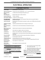
ELECTRICAL OPERATION . . . . . . . . . . . . . . . . . . . . . . . . . . . . . . . . . . . . . . . . . . . . . . . . . . . . . . . . . . . . . . . . . . . . . . . . . . . . . . . .
COMPONENT FUNCTION . . . . . . . . . . . . . . . . . . . . . . . . . . . . . . . . . . . . . . . . . . . . . . . . . . . . . . . . . . . . . . . . . . . . . . . . . . . .
SEQUENCE OF OPERATION . . . . . . . . . . . . . . . . . . . . . . . . . . . . . . . . . . . . . . . . . . . . . . . . . . . . . . . . . . . . . . . . . . . . . . . . .
PROGRAMMED COOKING . . . . . . . . . . . . . . . . . . . . . . . . . . . . . . . . . . . . . . . . . . . . . . . . . . . . . . . . . . . . . . . . . . . . . . .
WASHING CYCLE SEQUENCE OF OPERATIONS . . . . . . . . . . . . . . . . . . . . . . . . . . . . . . . . . . . . . . . . . . . . . . . .
USER PRESSES CLEAN BUTTON . . . . . . . . . . . . . . . . . . . . . . . . . . . . . . . . . . . . . . . . . . . . . . . . . . . . . . . . . . . . . . . .
CONTROLS EXPLANATION . . . . . . . . . . . . . . . . . . . . . . . . . . . . . . . . . . . . . . . . . . . . . . . . . . . . . . . . . . . . . . . . . . . . . . . . . .
MODEL KA7E . . . . . . . . . . . . . . . . . . . . . . . . . . . . . . . . . . . . . . . . . . . . . . . . . . . . . . . . . . . . . . . . . . . . . . . . . . . . . . . . . . . . .
MODEL KA7EM . . . . . . . . . . . . . . . . . . . . . . . . . . . . . . . . . . . . . . . . . . . . . . . . . . . . . . . . . . . . . . . . . . . . . . . . . . . . . . . . . . .
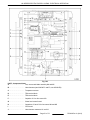
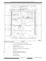
COMPONENT LOCATIONS . . . . . . . . . . . . . . . . . . . . . . . . . . . . . . . . . . . . . . . . . . . . . . . . . . . . . . . . . . . . . . . . . . . . . . . . . . .
MODEL KA7E . . . . . . . . . . . . . . . . . . . . . . . . . . . . . . . . . . . . . . . . . . . . . . . . . . . . . . . . . . . . . . . . . . . . . . . . . . . . . . . . . . . . .
MODEL KA7EM . . . . . . . . . . . . . . . . . . . . . . . . . . . . . . . . . . . . . . . . . . . . . . . . . . . . . . . . . . . . . . . . . . . . . . . . . . . . . . . . . . .
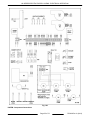
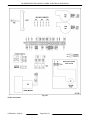
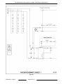
WIRING DIAGRAMS . . . . . . . . . . . . . . . . . . . . . . . . . . . . . . . . . . . . . . . . . . . . . . . . . . . . . . . . . . . . . . . . . . . . . . . . . . . . . . . . . .
KA7E - COMPONENT CONNECTIONS . . . . . . . . . . . . . . . . . . . . . . . . . . . . . . . . . . . . . . . . . . . . . . . . . . . . . . . . . . . .
KA7EM - COMPONENT CONNECTIONS . . . . . . . . . . . . . . . . . . . . . . . . . . . . . . . . . . . . . . . . . . . . . . . . . . . . . . . . . .
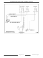
POWER CONNECTION . . . . . . . . . . . . . . . . . . . . . . . . . . . . . . . . . . . . . . . . . . . . . . . . . . . . . . . . . . . . . . . . . . . . . . . . . . .
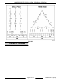
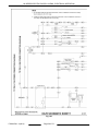
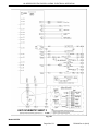
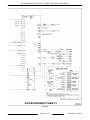
SCHEMATIC DIAGRAMS . . . . . . . . . . . . . . . . . . . . . . . . . . . . . . . . . . . . . . . . . . . . . . . . . . . . . . . . . . . . . . . . . . . . . . . . . . . . .
MODEL KA7E . . . . . . . . . . . . . . . . . . . . . . . . . . . . . . . . . . . . . . . . . . . . . . . . . . . . . . . . . . . . . . . . . . . . . . . . . . . . . . . . . . . . .
MODEL KA7EM . . . . . . . . . . . . . . . . . . . . . . . . . . . . . . . . . . . . . . . . . . . . . . . . . . . . . . . . . . . . . . . . . . . . . . . . . . . . . . . . . . .
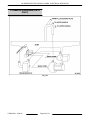
PLUMBING DIAGRAMS (KA7E ONLY) . . . . . . . . . . . . . . . . . . . . . . . . . . . . . . . . . . . . . . . . . . . . . . . . . . . . . . . . . . . . . . . .
46
46
46
46
47
47
48
48
49
50
50
52
54
54
55
56
57
57
59
62
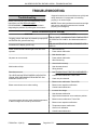
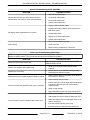
TROUBLESHOOTING . . . . . . . . . . . . . . . . . . . . . . . . . . . . . . . . . . . . . . . . . . . . . . . . . . . . . . . . . . . . . . . . . . . . . . . . . . . . . . . . . . . . . 64
TROUBLESHOOTING . . . . . . . . . . . . . . . . . . . . . . . . . . . . . . . . . . . . . . . . . . . . . . . . . . . . . . . . . . . . . . . . . . . . . . . . . . . . . . . . . 64
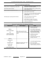
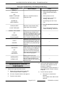
TROUBLESHOOT ROTOR COMPONENTS . . . . . . . . . . . . . . . . . . . . . . . . . . . . . . . . . . . . . . . . . . . . . . . . . . . . . . . . . . . 67
APPENDIX . . . . . . . . . . . . . . . . . . . . . . . . . . . . . . . . . . . . . . . . . . . . . . . . . . . . . . . . . . . . . . . . . . . . . . . . . . . . . . . . . . . . . . . . . . . . . . . . 69
REVERSING CONTROLS . . . . . . . . . . . . . . . . . . . . . . . . . . . . . . . . . . . . . . . . . . . . . . . . . . . . . . . . . . . . . . . . . . . . . . . . . . . . . 69
© HOBART SERVICE 2012
Page 3 of 72
F25294 Rev. A (0412)
KA SERIES ELECTRIC ROTARY OVENS - GENERAL
GENERAL
Oven cleaners are corrosive and can cause chemical burns. Rubber gloves, goggles and protective
clothing are required. Read and follow the instructions for the oven cleaner.
Safety standards require that, when the rotary oven’s electric supply line is properly connected to the
electrical power supply, an adequate means must be provided to limit movement of the oven without applying stress
to the electrical conduit. This means that, as part of the installation, the oven must be secured to either the wall or
the floor to limit movement of the oven and, thus, preventing damage to the flexible electrical conduit during cleaning,
maintenance and service operations.
REFERENCE INFORMATION
TSB'S & TSI'S
NOTE: Links or references to the TSB's are provided
here and in the appropriate sections of service
manual.
TSB 1381 KA7E ROTARY OVEN SCRAMBLED VFD DISPLAY.
TSB 1383
ROTISSERIE OVENS HR5E, HR7E AND KA7E NEW DRIVE MOTOR
ASSEMBLIES.
See Multimedia
section in TIS.
TSB 1400 KA7E - LEAKS AT DRIVE ARM GASKET DURING WASH CYCLE.
TSB 1417 KA7E - CLOGGING AT INPUT AND OUTPUT OF PERISTALTIC PUMPS.
See Multimedia
section in TIS.
HR7E AND KA7E ROTISSERIE OVEN ROTOR CRANK ARM DISENGAGING See Multimedia
FROM ROTOR.
section in TIS.
TSI
Instructions & Specifications
Model
Specifications
Instructions Manual
KA7E
F-40182
F-35521
KA7EM
F-40287
F-45111
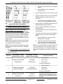
INTRODUCTION
•
Electronic control with message center, time,
temperature and program display features.
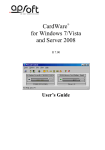
All pictures and illustrations shown are of a KA7E
unless otherwise specified. When specific model
number designations are needed for clarity, they are
added to the procedure or picture.
•
Pass through controls on the unload side to
snooze cook cycle, silence beeper and stop cook
cycle.
•
Equipped with grease assist and chemical
cleaner peristaltic pumps.
•
Pump for automatic draining.
General
•
Capacity of the KA series seven spit oven is 21
to 35 chickens.
•
Stacking kit available to stack ovens.
•
Refer to the Specifications sheet for oven
Installation details and Instructions manual for
operating and cleaning instructions.
KA7E - Model Description
•
Rotisserie oven with automatic clean cycle.
F25294 Rev. A (0412)
KA7EM - Model Description
•
Rotisserie oven without automatic clean cycle
features (manual cleaning).
•
Electronic control with time, temperature and
program display features.
•
Manual drain valve.
Page 4 of 72
KA SERIES ELECTRIC ROTARY OVENS - GENERAL
•
Equipped with grease assist and chemical
cleaner peristaltic pumps.
•
Available with a grease assist peristaltic pump to
remove grease during a cook cycle (optional).
•
VOM with AC current tester (Any VOM with a
sensitivity of at least 20,000 ohms per volt can be
used.)
•
Temperature Tester
•
Field Service Grounding Kit
•
Torque wrench capable of measuring up to 45 inlbs.
AMPERAGE
•
Jewelers screwdriver
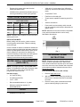
•
Power switch and momentary switch removal
tool (two required) made locally to dimensions in
graphic below
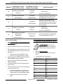
ELECTRICAL SPECIFICATIONS
KA7E AND KA7EM
VOLTS
PHASE
WATTAGE
208
1
9,300
42.8
208
3
9,300
24.7
240
1
9,300
37.7
240
3
9,300
21.8
NOTE: Separate power supplies must be used when
stacking two ovens.
NOTE: Material for tool can be aluminum, hard plastic
or any other hard material which can be easily
fabricated to dimensions.
INSTALLATION NOTE:
Before putting oven into service, check to ensure
incoming power terminal block TB6 wire retaining
screws are tight.
Ovens mounted on casters or installed on stands with
casters must be provided with an adequate restraining
means to guard against transmission of strain to the
electric supply line. Instructions for tethering are
included in stacking kit instructions and with optional
oven stand. Disconnect the flexible electrical
conduit(s) before disconnecting the restraint.
WATER SUPPLY REQUIREMENTS
(KA7E ONLY)
NOTE: For proper operation, use only HOT water
supply. For installations at the end of a long hot water
line, a second pre-rinse may be required to be
programmed to prime the line.
Hot water supply:
•
3/4" hose bib fitting.
•
0.5 GPM @ 25-50 PSI.
•
120°F - 140°F.
•
Recommended hardness, 4 - 6 grains.
•
Minimum conductivity required, 30
MICROMHOS/CM.
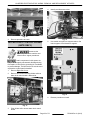
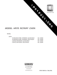
Fig. 1
ACCESSORY STAND
INSTRUCTIONS
NOTE: Separate units can be lifted by means of a
forklift. To do this, open both doors. Remove fan
cover. Slide forks all of the way thru top of oven. Make
sure forks rest on the frame member and are spread
as far apart as possible. Stacked units must not be
lifted in this manner.
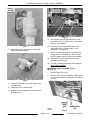
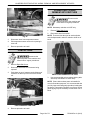
KA7E Self-Clean (ML-137701, ML-137709)
1.
Remove Right Side Cover.
2.
With oven lifted, remove drain plug and save it.
Drain hose is connected here and routed down
thru base.
3.
Remove electric power cord blank and install
proper restraining fitting for power cord.
TOOLS
•
Standard set of hand tools
Page 5 of 72
F25294 Rev. A (0412)
KA SERIES ELECTRIC ROTARY OVENS - GENERAL
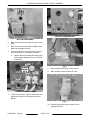
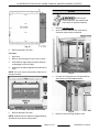
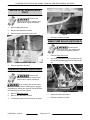
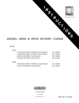
PREVIOUS CONSTRUCTION
BOTTOM VIEW SHOWN
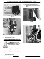
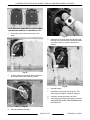
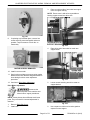
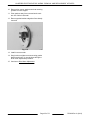
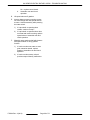
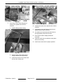
4.
Remove screws securing water fill valve to utility
plate.
5.
Remove screws securing drain manifold to utility
plate and utility plate to frame.
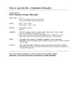
6.
Current construction - Remove strain relief nuts
securing chemical-in and grease-out hoses.
A.
Remove hoses from strain relief fittings (pull
hoses through fittings but leave connected
to machine).
Fig. 5
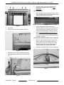
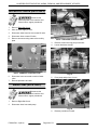
8.
Discard original utility plate, saving screws.
9.
Slide mounting bracket off water fill valve.
CURRENT CONSTRUCTION
7.
Previous construction - Remove chemical-in and
grease-out hoses from 45 degree strain relief
fittings.
Fig. 6
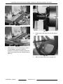
10. Reinstall mounting bracket to water fill valve
(rotated as shown).
F25294 Rev. A (0412)
Page 6 of 72
KA SERIES ELECTRIC ROTARY OVENS - GENERAL
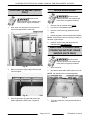
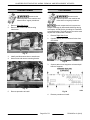
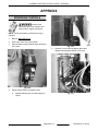
Fig. 9
15. Route water supply through the bottom of the
stand and connect. (Fittings mate to ¾ inch male
hose bib, not supplied.)
16. Route water drain through the bottom of the
stand and connect. (Fittings mate to 1 inch
female NPT, not supplied.)
Fig. 7
11. Install water valve onto bracket on new utility
plate (supplied with stand).
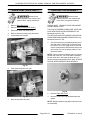
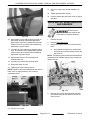
17. Route chemical-in and grease-out hoses down
through bottom of machine into stand. Connect
hoses to grease vessel and chemical container.
18. Route power cord thru base into oven and
connect to terminal block.
19. Proceed to Tether Bracket and Oven Mounting to
Stand (KA7E, KA7EM).
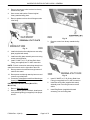
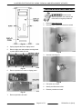
KA7EM with Grease Assist (ML-137710,
ML-137713)
1.
Remove Right Side Cover.
2.
Remove electric power cord blank. Install power
cord restraining fitting (not supplied) in the proper
hole E1.
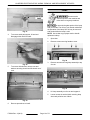
Fig. 8
12. Install new utility plate onto oven using screws
removed earlier.
13. Install drain plug removed earlier.
14. Install new hoses supplied with oven and route
down into base.
Fig. 10
Page 7 of 72
F25294 Rev. A (0412)
KA SERIES ELECTRIC ROTARY OVENS - GENERAL
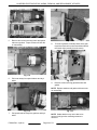
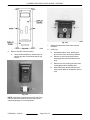
3.
Remove screws and valve bracket from factory
standard utility plate.
4.
Save screws and bracket. Discard original
factory standard utility plate.
5.
Remove grease-out hose from 45 degree strain
relief fitting.
Fig. 12
3.
Remove screws from factory standard utility
plate.
Fig. 11
6.
Install valve bracket from old plate onto new utility
plate (supplied with stand).
7.
Install new utility plate assembly onto oven using
screws removed earlier.
8.
Install ¾" MNPT to ¾" ID, 90 deg, Barb Hose
Fitting (not supplied) into P1 drain connection.
NOTE: P1 drain connection cannot drop through into
stand and must exit out the right side of the oven.
9.
Route grease-out hose down through bottom of
machine into stand.
10. Route power cord through stand up into oven and
connect to terminal block.
Fig. 13
11. Proceed to Tether Bracket and Oven Mounting to
Stand (KA7E, KA7EM).
4.
Install ¾" MNPT to ¾" ID, 90 deg, Barb Hose
Fitting (not supplied) into P1 drain connection.
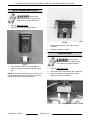
KA7EM without Grease Assist (ML-137711,
ML-137714)
5.
Install new utility plate (supplied with stand)
assembly onto oven using screws removed
earlier.
6.
Install Plug Button (supplied with stand
accessory) into new utility plate.
1.
Remove Right Side Cover.
2.
Remove electric power cord blank. Install power
cord restraining fitting (not supplied) in the proper
hole E1.
F25294 Rev. A (0412)
Page 8 of 72
KA SERIES ELECTRIC ROTARY OVENS - GENERAL
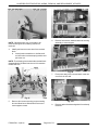
2.
Using holes in oven's caster mounting plate,
secure oven to stand using 4 screws and 4
washers provided with stand accessory. Install
washers such that bolt does not slip through.
Fig. 14
7.
Route power cord through stand up into oven and
connect to terminal block.
8.
Proceed to Tether Bracket and Oven Mounting to
Stand (KA7E, KA7EM).
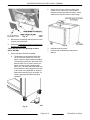
Tether Bracket and Oven Mounting to Stand
(KA7E, KA7EM)
1.
Fig. 16
3.
Install all removed covers.
4.
Continue with installation per Instructions
Manual.
Ensure that tether bracket is installed.
A.
The bracket must be installed along with
one of the swivel casters to a corner as
shown using the caster hardware provided.
The remaining open hole in the center of the
tether bracket is to be used to secure one
end of the tether (locally supplied chain,
cable, etc.). The other end of the tether is to
be secured to an anchoring point in the wall
or floor when oven installation is complete.
Make sure that during oven movement, no
stress is applied to the flexible electrical
conduit(s).
Fig. 15
Page 9 of 72
F25294 Rev. A (0412)
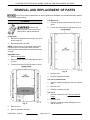
KA SERIES ELECTRIC ROTARY OVENS - REMOVAL AND REPLACEMENT OF PARTS
REMOVAL AND REPLACEMENT OF PARTS
Due to use of chemical detergents, all interior replacement hardware must be stainless steel hardware
as listed in the parts catalog.
Left Side Cover
COVERS
Disconnect the
electrical power to the machine and
follow lockout / tagout procedures.
1.
Remove ten screws securing left side cover to
frame.
2.
Loosen one screw securing top center of cover.
Pump Cover
1.
Remove two thumbscrews securing pump cover
and lift cover off.
2.
Reverse procedure to install.
NOTE: Anytime service is performed requiring the
right side cover to be removed, check to ensure
incoming power terminal block wire retaining screws
are tight.
Right Side Cover
1.
Remove Pump Cover.
2.
Remove twelve screws securing right side cover
to frame.
3.
Loosen one screw securing top center of cover.
Fig. 18
3.
Remove cover.
4.
Reverse procedure to install.
Top Cover (Control Panel)
1.
Remove screws securing top cover over controls
area.
2.
Remove cover.
3.
Reverse procedure to install.
Top Cover
Fig. 17
4.
Remove cover.
5.
Reverse procedure to install.
F25294 Rev. A (0412)
1.
Remove screws securing Top Cover (Control
Panel).
2.
Remove cover.
3.
Remove remaining screws securing top cover
and lift cover off.
Page 10 of 72
KA SERIES ELECTRIC ROTARY OVENS - REMOVAL AND REPLACEMENT OF PARTS
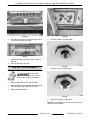
DOOR
Disconnect the
electrical power to the machine and
follow lockout / tagout procedures.
1.
Remove Left Side Cover.
2.
Open oven door and pull inner oven door to
overcome magnet hold to main door.
Fig. 19
4.
Reverse procedure to install.
Fan Cover
1.
Open door.
2.
Remove nut securing fan cover to top of cavity.
3.
Grab deflector edge and pivot edge toward you
to disengage cover from studs.
4.
Slide cover off studs at opposite side and remove
cover.
NOTE: Fan cover can be removed thru either door in
the same manner.
Fig. 21
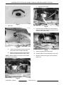
3.
VIEW - AS LOOKING THROUGH DOOR GLASS
5.
Reverse procedure to install.
NOTE: Make sure all six studs are engaged properly
and that the cover does not hang down.
Lift inner door hinge pins out of hinge bushings
and lay door on a flat padded surface.
Fig. 22
4.
Page 11 of 72
Remove screws securing facade to oven.
F25294 Rev. A (0412)
KA SERIES ELECTRIC ROTARY OVENS - REMOVAL AND REPLACEMENT OF PARTS
8.
Reverse procedure to install but leave nuts
securing hinge plate loose. Perform Door
Adjustment.
Door Adjustment
1.
Fig. 26
Fig. 23
5.
Close door.
6.
Remove nuts securing top hinge to cabinet.
With top hinge plate mounting nuts loose, use an
object to shim handle end of door to make bottom
of door parallel to the sump facade.
2.
Tighten hinge plate nuts and check door
operation. Make sure there is no interference or
rubbing when door is operated. Door must not
contact sump facade when opening or closing.
3.
Check Door Switch Adjustment (KA7E only; if
required). LED at CPU board input X22 should
be on when both doors are closed and both door
switches are closed.
Door Switch Adjustment (KA7E only; if required)
1.
With oven top facade removed to access door
switch, loosen switch mounting screws and
adjust switch as required. LED at CPU board
input X22 should be on when both doors are
closed and both door switches are closed.
2.
Install all covers and check for proper operation.
Fig. 24
7.
Carefully remove hinge plate while supporting
hinge backing plate and lift door off lower hinge
pin.
Fig. 27
Fig. 25
F25294 Rev. A (0412)
Page 12 of 72
KA SERIES ELECTRIC ROTARY OVENS - REMOVAL AND REPLACEMENT OF PARTS
DOOR SWITCH MAGNET (KA7E
ONLY)
OUTER DOOR GLASS
Disconnect the
electrical power to the machine and
follow lockout / tagout procedures.
Disconnect the
electrical power to the machine and
follow lockout / tagout procedures.
1.
Open oven door and pull inner oven door to
overcome magnet hold to main door.
1.
Remove door as outlined under DOOR.
2.
Lay door on a flat padded surface.
3.
Remove screws securing glass and remove
glass.
4.
Install new glass in same orientation as old glass.
NOTE: Avoid contact such as bumping or hitting, or
abrasion of glass edges.
5.
Install in reverse order and adjust door as
outlined under Door Adjustment.
WASH ARM, STRAINER PANS,
STRAIN PAN SUPPORT, DRAIN
SHROUD (KA7E ONLY)
Disconnect the
electrical power to the machine and
follow lockout / tagout procedures.
Fig. 28
2.
Remove screws securing magnet housing and
remove magnet.
1.
Open oven door.
2.
Use strainer pan handle and lift pan out of oven.
NOTE: Pan positions are not interchangeable.
Fig. 29
3.
Reverse procedure to install and check Door
Switch Adjustment (KA7E only; if required).
Fig. 30
3.
Page 13 of 72
To remove wash arm, unscrew knurled part of
wash arm.
F25294 Rev. A (0412)
KA SERIES ELECTRIC ROTARY OVENS - REMOVAL AND REPLACEMENT OF PARTS
LAMP
Disconnect the
electrical power to the machine and
follow lockout / tagout procedures.
Do not touch the glass portion of the lamp
with your hands. The oil from your hands could affect
the operation of the lamp. Skin oil may be removed
with alcohol while the lamp is cold.
Fig. 31
4.
NOTE: Use a clean rag or paper towel to handle
replacement lamp.
To remove strain pan support, lift end and
disengage other end from stud.
1.
Open door.
2.
Remove screws securing facade to oven.
Fig. 34
3.
Fig. 32
5.
Remove two nuts securing lamp assembly to top
of oven.
To remove drain shroud, remove nuts and
washers securing shroud and lift shroud out of
oven.
Fig. 35
4.
Lift lamp assembly out of oven and support it.
5.
Loosen screws in terminal block securing lamp
wires and pull wires out of block.
Fig. 33
6.
Reverse procedures to install.
F25294 Rev. A (0412)
Page 14 of 72
KA SERIES ELECTRIC ROTARY OVENS - REMOVAL AND REPLACEMENT OF PARTS
Fig. 38
Fig. 36
6.
Work lamp with wires out of lamp brackets. Wires
can not be removed from lamp.
4.
Remove washer from both shafts.
Fig. 37
7.
Install and tighten insulators evenly to prevent
damage.
8.
Reverse procedure to install.
Fig. 39
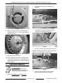
FAN MOTORS ASSEMBLY
5.
Remove C clip from both shafts.
Disconnect the
electrical power to the machine and
follow lockout / tagout procedures.
1.
Remove Right Side Cover and Fan Cover.
2.
Remove wing nut securing each fan blade. Nut is
left hand thread, turn clockwise to remove.
3.
Remove both fan blades.
Fig. 40
6.
Unscrew both fan mounting nuts.
NOTE: Check condition of o-ring on fan mounting nut
and replace if necessary.
Page 15 of 72
F25294 Rev. A (0412)
KA SERIES ELECTRIC ROTARY OVENS - REMOVAL AND REPLACEMENT OF PARTS
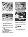
C.
Work pipe out of oven.
Fig. 41
7.
KA7E only:
Fig. 44
8.
Insert two large screwdrivers or similar objects
that can lift fan motor assembly enough for motor
shafts to clear inside ceiling.
Fig. 42
A.
Loosen hose clamp and remove hose from
control side nozzle and pipe assembly.
B.
Remove screws and nuts securing control
side nozzle pipe assembly to top of oven.
NOTE: Check condition of o-rings on screw heads
and replace if necessary.
Fig. 45
9.
10. Carefully slide fan motor assembly out of cavity.
11. Remove screws securing fan motor assembly
and lift out.
Fig. 43
F25294 Rev. A (0412)
Identify and disconnect motor wires.
Page 16 of 72
KA SERIES ELECTRIC ROTARY OVENS - REMOVAL AND REPLACEMENT OF PARTS
2.
Disconnect lead wires from element being
replaced.
Fig. 48
Fig. 46
12. Remove o-ring from old fan motor shaft and
install on new fan motor. If not in good condition,
install new o-ring.
3.
Use a wrench on element inside oven while
removing and installing mounting nut.
Fig. 49
4.
Remove nuts securing element being replaced.
NOTE: If mounting nuts will not slide over wire lead
backup nuts, loosen them or remove them.
Fig. 47
13. Reverse procedure to install.
14. After installing the fan blade, verify that it does
not rub the top of the cavity. If required, remove
fan blade and tighten fan mounting nut (shown in
Step 6 above).
HEATING ELEMENTS
Disconnect the
electrical power to the machine and
follow lockout / tagout procedures.
1.
Fig. 50
5.
Remove screws securing element support
bracket to ceiling and remove bracket.
Remove Right Side Cover and Fan Cover.
Page 17 of 72
F25294 Rev. A (0412)
KA SERIES ELECTRIC ROTARY OVENS - REMOVAL AND REPLACEMENT OF PARTS
Fig. 53
Fig. 51
6.
Slide element out of wall.
7.
Clean off old gasket that may stick to wall or
washer and replace with new gasket (not
included with element).
3.
Disconnect wires from high limit thermostat.
4.
Remove screws securing high limit to frame.
Fig. 54
Fig. 52
5.
8.
Reverse procedure to install.
9.
Torque element mounting nuts to 45in-lbs. Use
backup wrench on element inside oven to
prevent twisting and damage to element.
NOTE: Set the high limit thermostat to its maximum
clockwise position.
TEMPERATURE SENSOR
10. Torque nuts securing wires onto element to 1420in-lbs. Use a backup wrench on back nut to
prevent twisting and damage to element.
Disconnect the
electrical power to the machine and
follow lockout / tagout procedures.
HIGH LIMIT THERMOSTAT
Disconnect the
electrical power to the machine and
follow lockout / tagout procedures.
1.
Remove Right Side Cover.
2.
Pull high limit probe out of hole located in top right
hand corner.
F25294 Rev. A (0412)
Reverse procedure to install.
1.
Remove Right Side Cover.
2.
Remove screw and nut securing temperature
sensor to mounting bracket.
Page 18 of 72
KA SERIES ELECTRIC ROTARY OVENS - REMOVAL AND REPLACEMENT OF PARTS
POWER SWITCH AND
MOMENTARY SWITCHES
Disconnect the
electrical power to the machine and
follow lockout / tagout procedures.
NOTE: Momentary switches on KA7E only.
1.
Remove Right Side Cover.
2.
Disconnect wires from switch.
NOTE: There are four tabs (two at each end) that
must be depressed in order for switch to slide out of
bezel.
Fig. 55
3.
Disconnect wires from temperature sensor.
4.
Pull temperature sensor out thru the opening in
oven wall.
5.
Reverse procedure to install.
CONTACTORS
Disconnect the
electrical power to the machine and
follow lockout / tagout procedures.
1.
Remove Right Side Cover.
2.
Disconnect lead wires from contactor being
replaced.
3.
Push down on top of contactor and pull bottom of
contactor out then up to remove it from the din
rail.
SWITCH DISASSEMBLED FOR VIEW
3.
Use recommended tools to release locking tabs
at both top and bottom of switch body.
NOTE: Picture below shows parts not installed in
oven for illustration purposes. It is recommended that
you fully insert tools and gently spread tool ends apart
as shown. Then gently pull switch out of bezel. Some
gentle prying may be necessary to start switch out of
bezel.
PARTS REMOVED FOR VIEW
4.
Reverse procedure to install.
Page 19 of 72
F25294 Rev. A (0412)
KA SERIES ELECTRIC ROTARY OVENS - REMOVAL AND REPLACEMENT OF PARTS
2.
Unplug ribbon cable from display board.
A.
Spread retaining clips to extract plug from
socket.
Fig. 58
Fig. 60
3.
Remove six nuts securing display panel with
display board attached and lift out of oven.
Fig. 59
4.
Push switch out of bezel.
5.
Reverse procedure to install.
DISPLAY BOARD AND KEYPAD
Disconnect the
electrical power to the machine and
follow lockout / tagout procedures.
Fig. 61
Certain components in this system are
subject to damage by electrostatic discharge during
field repairs. A field service grounding kit is available
to prevent damage. The field service grounding kit
must be used anytime the control board is handled.
TSB 1381 KA7E ROTARY OVEN SCRAMBLED VFD
DISPLAY.
1.
Remove Right Side Cover.
F25294 Rev. A (0412)
Page 20 of 72
KA SERIES ELECTRIC ROTARY OVENS - REMOVAL AND REPLACEMENT OF PARTS
ROTOR STOP/START SWITCH
Disconnect the
electrical power to the machine and
follow lockout / tagout procedures.
1.
Remove Right Side Cover.
2.
Unscrew black knob and remove from switch.
Fig. 62
4.
Unplug keypad cable from display board.
5.
Remove eight nuts and washers securing board
to panel and lift board off studs.
Fig. 65
3.
Unscrew mounting nut.
Fig. 63
6.
Remove spacers from studs on display panel.
Fig. 66
4.
Pull switch out of hole.
5.
Identify and disconnect wires.
6.
Reverse procedure to install.
Fig. 64
7.
Reverse procedure to install.
Page 21 of 72
F25294 Rev. A (0412)
KA SERIES ELECTRIC ROTARY OVENS - REMOVAL AND REPLACEMENT OF PARTS
MEAT PROBE MINI JACK
Disconnect the
electrical power to the machine and
follow lockout / tagout procedures.
1.
Remove Right Side Cover.
2.
Mini jack is located under power switch.
Fig. 68
4.
Identify and disconnect wires from mini jack
terminals.
5.
Reverse procedure to install.
CAPACITORS
Disconnect the
electrical power to the machine and
follow lockout / tagout procedures.
Fig. 67
3.
Use a small screwdriver or similar object to
carefully pry tabs out and work retainer clip off
jack.
NOTE: Jack shown removed from oven for view. Also
notice that wires are polarity sensitive and must be
connected properly for correct operation.
1.
Remove Right Side Cover.
2.
Disconnect wires from capacitor being replaced.
3.
Remove hardware securing capacitor being
replaced and remove capacitor.
Fig. 69
F25294 Rev. A (0412)
Page 22 of 72
KA SERIES ELECTRIC ROTARY OVENS - REMOVAL AND REPLACEMENT OF PARTS
4.
Identify and disconnect wires.
Fig. 70
4.
Reverse procedure to install.
Fig. 72
WATER LEVEL CONTROL BOARD
(KA7E ONLY)
5.
Use needle nose pliers to squeeze tabs on five
board supports. Work board off supports.
Disconnect the
electrical power to the machine and
follow lockout / tagout procedures.
Certain components in this system are
subject to damage by electrostatic discharge during
field repairs. A field service grounding kit is available
to prevent damage. The field service kit must be used
anytime the control board is handled.
1.
Remove Right Side Cover.
2.
Remove four screws securing divider wall that
water level control board is fastened to.
Fig. 73
6.
Reverse procedure to install.
Fig. 71
3.
Pivot divider wall to access water level control
board.
Page 23 of 72
F25294 Rev. A (0412)
KA SERIES ELECTRIC ROTARY OVENS - REMOVAL AND REPLACEMENT OF PARTS
WATER LEVEL SENSOR (KA7E
ONLY)
Disconnect the
electrical power to the machine and
follow lockout / tagout procedures.
1.
Remove Right Side Cover.
2.
Remove wire attached to sensor.
3.
Unscrew sensor and remove from oven.
Fig. 75
4.
Reverse procedure to install.
WASH PUMP RELAY (KA7E ONLY)
Disconnect the
electrical power to the machine and
follow lockout / tagout procedures.
1.
Remove Right Side Cover.
2.
Use small screwdriver to pry out release tab, lift
front of relay and disengage rear of relay from din
rail.
PARTS REMOVED FOR VIEW
4.
Reverse procedure to install.
CHEMICAL SENSOR (KA7E ONLY)
Disconnect the
electrical power to the machine and
follow lockout / tagout procedures.
Oven cleaners are corrosive and
can cause chemical burns. Rubber gloves, goggles
and protective clothing are required. Read and follow
the instructions for the oven cleaner.
1.
Remove Right Side Cover.
2.
Remove wire attached to sensor.
3.
Loosen hose clamps and work hoses off sensor.
F25294 Rev. A (0412)
Fig. 76
3.
Identify and disconnect wires.
4.
Reverse procedure to install.
Page 24 of 72
KA SERIES ELECTRIC ROTARY OVENS - REMOVAL AND REPLACEMENT OF PARTS
TRANSFORMER
CPU BOARD
Disconnect the
electrical power to the machine and
follow lockout / tagout procedures.
1.
Remove Right Side Cover.
2.
Remove two screws and nuts securing
transformer.
Disconnect the
electrical power to the machine and
follow lockout / tagout procedures.
Certain components in this system are
subject to damage by electrostatic discharge during
field repairs. A field service grounding kit is available
to prevent damage. The field service kit must be used
anytime the control board is handled.
1.
Remove Right Side Cover.
2.
Carefully identify and disconnect all wires from
CPU board.
Fig. 77
3.
Identify and disconnect wires to transformer.
4.
Unscrew nut and remove mounting bracket.
Fig. 79
3.
Squeeze tabs on one support at a time and pull
board off supports.
Fig. 78
5.
Fig. 80
Reverse procedure to install.
4.
Page 25 of 72
Reverse procedure to install.
F25294 Rev. A (0412)
KA SERIES ELECTRIC ROTARY OVENS - REMOVAL AND REPLACEMENT OF PARTS
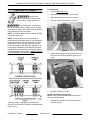
Pump Removal
PERISTALTIC PUMPS
Disconnect the
electrical power to the machine and
follow lockout / tagout procedures.
1.
Remove Right Side Cover.
2.
Disconnect wires for pump to be removed.
3.
Disconnect hoses for pump to be removed.
4.
Remove screws securing pump to frame.
Oven cleaners are corrosive and
can cause chemical burns. Rubber gloves, goggles
and protective clothing are required. Read and follow
the instructions for the oven cleaner.
NOTE: Procedure applies to KA7E; and the KA7EM
with grease assist only.
NOTE: KA7E rotisserie ovens previously were
produced with 3 peristaltic pumps - a gray water/sump
pump, grease pump, and chemical pump. The gray
water/sump pump is no longer required in current
production beginning with Serial No. 46300096. The
pump system parameters have changed so that the
main drain pump (not pictured) removes any lingering
gray water from the sump. Refer to SERVICE MODE
- PROGRAMMING AND DIAGNOSTICS for
Programming parameters
Fig. 82
5.
Rotate pump slightly counterclockwise to line up
with cutout in frame and withdraw pump out of
frame.
Fig. 83
6.
Reverse procedure to install.
Procedure to Replace Pump Hose
NOTE: Only use recommended replacement hose
found in the parts catalog.
Fig. 81
1.
TSB 1417 KA7E - CLOGGING AT INPUT AND
OUTPUT OF PERISTALTIC PUMPS. See Multimedia
section in TIS.
F25294 Rev. A (0412)
Page 26 of 72
Remove three screws securing face plate and
pull face plate off.
KA SERIES ELECTRIC ROTARY OVENS - REMOVAL AND REPLACEMENT OF PARTS
KA7E PREVIOUS CONSTRUCTION WITH GREY
WATER/SUMP PERISTALTIC SHOWN ON LEFT
2.
Disconnect hose ends and work hose out of
pump.
Fig. 87
5.
Install new hose. Work hose around cavity and
manually turn rollers as hose is positioned. Make
sure hose clamp is in cutout to hold hose in
position.
Fig. 85
3.
If rollers need to be removed, use a screwdriver
and release both sides of retaining clamp.
Fig. 88
6.
Install face plate.
7.
Install hose clamps and connect hoses. Trim
discharge hose length if needed for proper fit.
8.
Complete reversing procedure to install.
9.
Verify that pump is working properly as outlined
under SERVICE MODE - PROGRAMMING AND
DIAGNOSTICS.
Fig. 86
4.
Pull roller assembly off shaft.
Page 27 of 72
F25294 Rev. A (0412)
KA SERIES ELECTRIC ROTARY OVENS - REMOVAL AND REPLACEMENT OF PARTS
WATER FILL VALVE (KA7E ONLY)
Disconnect the
electrical power to the machine and
follow lockout / tagout procedures.
1.
Remove Right Side Cover.
2.
Shut off water supply to oven.
3.
Disconnect water hose into oven water fill valve.
4.
Disconnect wires to water fill valve.
5.
Remove screws securing water valve to utility
plate.
KA7E - PREVIOUS CONSTRUCTION
3.
Remove screws securing pump to bracket.
4.
Loosen both hose clamps.
KA7E - CURRENT CONSTRUCTION
Fig. 91
6.
Disconnect hose connected to outlet of water
valve.
7.
Reverse procedure to install.
5.
Pivot pump and pull out of oven.
WASH PUMP (KA7E ONLY)
Disconnect the
electrical power to the machine and
follow lockout / tagout procedures.
1.
Remove Right Side Cover.
2.
Disconnect wires from wash pump.
Fig. 92
6.
F25294 Rev. A (0412)
Page 28 of 72
Reverse procedure to install.
KA SERIES ELECTRIC ROTARY OVENS - REMOVAL AND REPLACEMENT OF PARTS
DRAIN PUMP (KA7E ONLY)
DRIVE MOTOR ASSEMBLY
Disconnect the
electrical power to the machine and
follow lockout / tagout procedures.
Disconnect the
electrical power to the machine and
follow lockout / tagout procedures.
1.
Remove Right Side Cover.
2.
Remove WASH PUMP (KA7E ONLY).
3.
Disconnect wires from drain pump.
4.
Remove screws securing pump to bracket.
5.
Loosen both hose clamps.
TSB1400 KA7E - LEAKS AT DRIVE ARM GASKET
DURING WASH CYCLE.
TSB 1383 ROTISSERIE OVENS HR5E, HR7E AND
KA7E NEW DRIVE MOTOR ASSEMBLIES. See
Multimedia section in TIS.
TSI HR7E AND KA7E ROTISSERIE OVEN ROTOR
CRANK ARM DISENGAGING FROM ROTOR. See
Multimedia section in TIS.
1.
Check that crank arm is stopped pointing to the
side that has the interior light (or pointing away
from motor). If it is not, apply power to unit and
use the rotate switch to start and stop drive motor
when crank arm is in the proper position. Then
disconnect power.
NOTE: If there is a motor malfunction and you cannot
position the crank arm, you will be able to manually
put the crank arm in the proper position after you
remove the motor and speed reducer. Refer to DRIVE
MOTOR, SPEED REDUCER AND GEARBOX.
Fig. 93
6.
Pivot pump and pull out of oven.
Fig. 95
Fig. 94
7.
Reverse procedure to install.
2.
Remove Right Side Cover.
3.
Remove screws securing gasket bracket and
gasket.
NOTE: Replace washers and gasket with new ones
on reassembly.
Page 29 of 72
F25294 Rev. A (0412)
KA SERIES ELECTRIC ROTARY OVENS - REMOVAL AND REPLACEMENT OF PARTS
KA7E - PREVIOUS CONSTRUCTION SHOWN
Fig. 96
6.
NOTE: Gasket bracket may not be able to be
removed until gear box mounting screws are
removed.
4.
Remove four screws, washers and nuts securing
assembly to motor support.
Identify and remove motor wires from terminal
block.
A.
Insert jeweler screwdriver or similar small
tool into holes to release spring tension and
pull wires out.
NOTE: The following picture shows the terminal block
disassembled to illustrate how the tool is inserted to
release the wire.
Fig. 99
7.
Pivot motor away from oven and work crank arm
out of hole in side wall.
Fig. 97
5.
Remove four screws securing pump mounting
box and allow box to slide down for access to
motor support screws.
F25294 Rev. A (0412)
Fig. 100
8.
Page 30 of 72
Remove gasket bracket and gasket if not already
removed.
KA SERIES ELECTRIC ROTARY OVENS - REMOVAL AND REPLACEMENT OF PARTS
3.
Place non-driven side of rotor shaft onto upper
notch of support bearing.
NOTE: Ensure rotor is slid as far as possible on
bearing support toward non-drive side.
Fig. 101
9.
If replacing any individual piece, remove four
screws securing motor and speed reducer to
gearbox. Torque screws to 22 inch lbs. on
reassembly.
Fig. 103
4.
Place drive end of rotor shaft on crank arm
support notch.
MOTOR ALREADY REMOVED
10. Install in reverse order.
11. Snug but do not tighten screws securing gasket
bracket at this time. Bracket and gasket must be
loose during the drive motor adjustment
procedure.
12. Continue to Drive Motor Adjustment.
Fig. 104
5.
Drive Motor Adjustment
Loosen screws securing rotor drive motor to
support bracket.
Disconnect the
electrical power to the machine and
follow lockout / tagout procedures.
NOTE: Some pictures show different model oven
parts. They are used for view and adjustment is
identical.
1.
Remove Right Side Cover.
2.
Install rotor.
Fig. 105
6.
Page 31 of 72
Use a square or similar tool to make gearbox
square to motor support.
F25294 Rev. A (0412)
KA SERIES ELECTRIC ROTARY OVENS - REMOVAL AND REPLACEMENT OF PARTS
Fig. 106
Fig. 108
8.
Rotate rotor to align crank arm pins with slots on
rotor.
Fig. 107
7.
Slide gearbox in or out, while keeping it square
to motor support, until there is sufficient
clearance for rotor shaft to be lifted off and on the
support notch without the end of shaft contacting
crank arm.
Fig. 109
9.
F25294 Rev. A (0412)
Page 32 of 72
Slide rotor toward crank arm to engage pins.
KA SERIES ELECTRIC ROTARY OVENS - REMOVAL AND REPLACEMENT OF PARTS
17. Check for proper removal and installation of
rotor.
18. Tighten gasket bracket screws.
19. Continue reassembly and check oven for proper
operation.
DRIVE MOTOR, SPEED REDUCER
AND GEARBOX
Disconnect the
electrical power to the machine and
follow lockout / tagout procedures.
Fig. 110
10. Apply power to oven and carefully jog motor to
place crank pointing toward side with interior
light. Ensure crank arm is parallel with oven wall.
Position motor as necessary while maintaining
adjustment in previous step.
11. Jog motor to point crank arm to opposite side of
oven. Ensure crank arm is parallel with oven wall.
Position motor as necessary while maintaining
adjustment in previous steps.
12. Repeat steps 6 thru 11 as necessary until
conditions are met.
1.
Remove the rotor.
2.
Remove Right Side Cover.
3.
Identify and remove motor wires from terminal
block.
A.
Insert jeweler screwdriver or similar small
tool into holes to release spring tension and
pull wires out.
NOTE: The following picture shows the terminal block
disassembled to illustrate how the tool is inserted to
release the wire.
13. Jog motor to put crank arm pointing down.
14. Disconnect power to oven.
15. Tighten gear case mounting screws.
NOTE: Non-drive end rotor shaft should seat itself in
lower notch of support bearing. This is normal
operating position.
Fig. 112
4.
Remove four screws securing pump mounting
box and allow box to slide down for access to
motor screws.
Fig. 111
16. Lift rotor out of oven.
Page 33 of 72
F25294 Rev. A (0412)
KA SERIES ELECTRIC ROTARY OVENS - REMOVAL AND REPLACEMENT OF PARTS
KA7E - PREVIOUS CONSTRUCTION SHOWN
5.
Remove four screws securing motor and speed
reducer to gearbox. Torque screws to 22 inch lbs.
on reassembly.
Fig. 116
8.
To remove gearbox, manually rotate worm gear
to position crank arm to point toward the side with
the interior light (or away from the motor).
Fig. 114
6.
Pull motor away from speed reducer and lay it
aside.
Fig. 117
9.
Remove screws securing gasket bracket and
gasket.
NOTE: Replace washers and gasket with new ones
on reassembly.
Fig. 115
7.
Fig. 118
Pull speed reducer away from gearbox and lay it
aside.
F25294 Rev. A (0412)
NOTE: Gasket bracket may not be able to be
removed until gear box mounting screws are
removed.
Page 34 of 72
KA SERIES ELECTRIC ROTARY OVENS - REMOVAL AND REPLACEMENT OF PARTS
10. Remove four screws, washers and nuts securing
gearbox to motor support.
11. Pivot gearbox away from oven and work crank
arm out of hole in side wall.
12. Remove gasket bracket and gasket if not already
removed.
Fig. 119
13. Install in reverse order.
14. Snug but do not tighten screws securing gasket
bracket at this time. It must be loose during the
drive motor adjustment procedure.
15. Continue to Drive Motor Adjustment.
Page 35 of 72
F25294 Rev. A (0412)
KA SERIES ELECTRIC ROTARY OVENS - SERVICE PROCEDURES AND ADJUSTMENTS
SERVICE PROCEDURES AND ADJUSTMENTS
SERVICE MODE - PROGRAMMING
AND DIAGNOSTICS
NOTE: Service Mode allows access to the
programming parameters and diagnostic tests to
check the oven settings and the electrical component
functionality. Additionally, on KA7E machines a
DEMO MODE can be utilized as a continuation of the
diagnostic tests that allow the technician to manually
step through and verify clean cycle operation without
having to run an actual clean cycle.
NOTE: The P key is used to toggle the minus sign on
and off. Use this key if a negative value must be
entered. Entering an invalid number results in the time
display being set to 0 and a beep-beep will sound
indicating you should key in a new value.
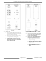
2.
Press and hold keys 1, 2, and 3 at the same time
while turning power switch on.
3.
Display shows ID in the temperature window and
ON or OFF in the time window.
4.
Turn power switch off and then back on to return
to operator mode.
5.
Repeat steps 1 thru 4 to toggle back.
Procedure to Toggle Between 9 and 99 Programs
1.
Turn power switch off.
2.
Press and hold keys PROBE, ENTER, and 2 at
the same time while turning power switch on.
3.
Display shows 9 or 99 in temperature window
and PROG in the time window.
4.
Turn power switch off and then back on to return
to operator mode.
5.
Repeat steps 1 thru 4 to toggle back.
Procedure to Enter Service Mode
1.
Turn power switch off.
2.
Press and hold keys CLOCK, 7, and 8 at the
same time while turning power switch on.
3.
Displays shows flashing P in temperature
window which indicates you are in service mode.
4.
Press number key(s) to enter Parameter Number
according to the chart below, then press ENTER
key.
A.
5.
Either accept this value by pressing ENTER key
or key in new value and then press ENTER key
to accept it.
A.
6.
Time display will flash showing current value
of the parameter.
P will flash in temperature window indicating
a new parameter number can be entered.
To save parameter settings and exit service
mode, turn the power switch to off. The unit will
remember the changes. After the power is turned
off, power can be disconnected from unit if
necessary to complete repairs.
KA7E DISPLAY SHOWN
Service Mode Parameters
Procedure to Toggle Between No ID and Operator
ID Mode
1.
Turn power switch off.
PROGRAMMING, ALL SOFTWARE VERSIONS
Parameter
Number
0
Description
Time display will show software version (Read Only).
F25294 Rev. A (0412)
Page 36 of 72
KA7E
KA7EM
X
X
KA SERIES ELECTRIC ROTARY OVENS - SERVICE PROCEDURES AND ADJUSTMENTS
PROGRAMMING, ALL SOFTWARE VERSIONS
Parameter
Number
Description
KA7E
KA7EM
X
X
X
X
X
X
X
X
X
X
0 = Fahrenheit. F 0 will display in Time window. Default = 0
1 = Celsius. C 1 will display in Time window.
1
FC will display in Program window.
If the temperature display option is changed, you will see a slight pause as all
stored cook programs are converted to new units.
0 = AM/PM. AP 0 will display in Time window. Default = 0
2
1 = 24 hour clock. 24 1 will display in Time window.
CL will display in Program window.
Future use - To be used when connected to remote computer.
3
0 = ASCII serial protocol. 0 will display in Time window. Default = 0
1 = Binary serial protocol. 1 will display in Time window.
SP will display in Program window.
Future use - To be used when connected to remote computer.
4
Oven ID number Range = 0 to 31. The number entered will display in Time window.
Default = 0
ID will display in Program window.
Temperature offset. Difference between sensor temperature and displayed
temperature value; used to correct for the difference between sensor and cooking
chamber temperature if any.
5
Range = +30 to -30. The number entered will display in Time window. Default = 0
C or F depends on unit selected.
OS will display in Program window.
NOTE: In the table below, an asterisk (*) beside
Parameter Number indicates a Service Only
parameter that must be unlocked to verify or edit the
setting as outlined in the following procedure. After the
unlock code is entered, any of the Service Only
parameters are viewable.
1.
Press 72 and select ENTER (parameter to unlock
service only parameters.
2.
Press 1972 and select ENTER (code to unlock
service only parameters) (1 beep).
3.
Enter desired Parameter Number containing an
asterisk (*) and verify or edit the setting as
necessary.
4.
After all desired Parameter Numbers are
checked, press 0 (zero) and select ENTER.
Normal programming can continue.
5.
Verify the remaining Parameter numbers as
necessary.
PROGRAMMING CONTINUED, CURRENT SOFTWARE VERSION C027
Parameter
Number
Setting
Description
31
43
Chemical pump ON time in seconds (default = 43). Time required may
vary for type of chemical used.
KA7E KA7EM
X
---
CP will display in Program window.
Page 37 of 72
F25294 Rev. A (0412)
KA SERIES ELECTRIC ROTARY OVENS - SERVICE PROCEDURES AND ADJUSTMENTS
PROGRAMMING CONTINUED, CURRENT SOFTWARE VERSION C027
Parameter
Number
Setting
*32
10
*33
2
34
120
35
2
*36
2
Description
Preheat time in minutes (default = 10)
PH will display in Program window.
Main Drain pump ON time in minutes (default = 2)
SP will display in Program window.
Chemical wash time in minutes (default = 120)
Ct will display in Program window.
Number of rinse cycles (default = 2)
nr will display in Program window.
Rinse time in minutes (default = 2)
Rt will display in Program window.
KA7E KA7EM
X
X
X
---
X
---
X
---
X
---
X
---
X
---
X
---
X
---
X
X
X
X
X
---
X
---
X
---
X
---
X
---
Number of pre-rinses (default = 1).
37
1
nP will displayed in Program window.
Increase pre-rinse number if initial fill is not hot enough.
38
0
39
0
Leave setting at 0 and advance to next program number.
Ft will display in Program window.
Leave setting at 0 and advance to next program number.
LC will display in Program window.
Water fill time limit in minutes (default = 5)
*40
5
FL will display in Program window.
Add time as necessary if water pressure is low.
Cool down temperature in Fahrenheit (default = 150)
*41
150
Ct will display in Program window.
Oven must cool to this temperature before next operation can start.
*42
150
*43
200
44
0
Preheat temperature in Fahrenheit (default = 150)
CP will display in Program window.
Drying temperature in Fahrenheit (default = 200)
Cd will display in Program window.
Demo Mode. Leave setting at 0 (zero) and continue to the next
Program Number. See DEMO MODE in the next section.
dE will display in Program window.
*45
15
48
4
49
4
F25294 Rev. A (0412)
Additional fill time in seconds (default = 10)
0F will display in Program window.
Wash pump ON time during cleaning (default = 4)
Pr is display in Program window.
Wash pump OFF time during cleaning (default = 4)
SO will display in Program window.
Page 38 of 72
KA SERIES ELECTRIC ROTARY OVENS - SERVICE PROCEDURES AND ADJUSTMENTS
PROGRAMMING CONTINUED, CURRENT SOFTWARE VERSION C027
Parameter
Number
93
Setting
---
Description
KA7E KA7EM
0 (zero) will display in time window as the initial value. Used to set
all parameters to default and clear all recipes.
Set value to 73 and press Enter. Machine is set to factory default
settings.
X
X
PROGRAMMING CONTINUED, PREVIOUS SOFTWARE VERSION dA09
Parameter
Number
31
Setting
Description
KA7E
---
80
Chemical pump ON time in seconds (default = 80). Time required may
vary for type of chemical used.
X
---
X
---
X
---
X
---
X
---
x
x
CP will displayed in Program window.
34
120
37
2
Chemical wash time in minutes (default = 120)
Ct will displayed in Program window.
Number of pre-rinses (default = 1). Increase if initial fill is not hot
enough.
nP will displayed in Program window.
48
4
49
4
93
---
Wash pump ON time during cleaning (default = 1)
Pr will displayed in Program window.
Wash pump OFF time during cleaning (default = 7)
SO will displayed in Program window.
0 (zero) will display in time window as the initial value. Used to set
all parameters to default and clear all recipes.
Set value to 73 and press Enter. Machine is set to factory default
settings.
DIAGNOSTICS, ALL SOFTWARE VERSIONS
Parameter
Number
Description
KA7E
KA7EM
X
X
X
X
KA7E
KA7EM
Press 1 - Operates CR1 "Lights" at terminal X1
X
X
Press 2 - Operates CR2 "Fans" at terminal X2
X
X
Display Test
20
All segments and LEDs are cycled to check operation.
When complete, oven will beep and be ready for the next Parameter Number
entry.
Keypad Test
21
22
When keys are pressed one at a time, the time display will indicate which one.
When no keys are pressed, the display should be blank. If not blank, indicates
a stuck key. Exit service mode by turning power switch off and then on again.
Enter service mode again if necessary.
Relay Test, components should function
Page 39 of 72
F25294 Rev. A (0412)
KA SERIES ELECTRIC ROTARY OVENS - SERVICE PROCEDURES AND ADJUSTMENTS
DIAGNOSTICS, ALL SOFTWARE VERSIONS
Parameter
Number
Description
KA7E
KA7EM
X
X
X
X
Press 5 - Operates CR5 "Sump/ Main Drain Motor" at terminal X5
X
---
Press 6 - Operates CR6 "Wash Pump" at terminal X6 (door(s) must be closed)
X
---
Press 7 - Operates CR7 "Chemical Pump" at terminal X7
X
---
Press 8 - Operates CR8 "Sump Fill Valve" at terminal X8
X
---
X
X
X
---
KA7E
KA7E
X
---
Digit 1 - Press rotate switch to test input to CPU board (X16).
X
X
Digit 2 - Fill Me input to CPU board ( X17 ). Ground the probe to a metal surface
on machine to test (approximately 3 second time delay).
X
---
Digit 3 - Low Level Input (X18). Ground the chemical probe sensor to a metal
surface on machine to test (approximately 3 second time delay).
X
---
Digit 4 - Press stop switch at rear of machine to test input to CPU board(X19).
X
---
Digit 5 - Press silence switch at rear of machine to test input (X20).
X
---
Digit 6 - Press snooze switch at rear of machine to test input (X21).
X
---
Digit 7 - Open door(s) to test. The input to CPU board is removed from (X22).
Close door(s) and input is back ON.
X
---
Digit 8 & 9 - Future Use.
X
---
Press ENTER to exit this test.
X
---
Press 3 - Operates CR3 "Rotate Motor" at terminal X3
Press 4 - Operates CR4 "Contactor K1" at terminal X4
NOTE: Contactor K2 is already energized thru power switch & high limit.
Press 9 - Operates CR9 "Grease drain" at terminal X9.
NOTE: KA7EM with grease assist option only.
Press 0 - Operates CR10 "Gray water/sump peristaltic" at terminal X10.
Press ENTER to exit this test.
NOTE: Gray water/sump peristaltic removed from ovens with Serial No.
46300096 and higher.
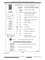
23
CPU Board Input Test, display indicates function
This tests for 24VAC input on X16 thru X24 to the CPU board. Uses one of
the 9 digits on the front display for each of the inputs (digit 8 & 9 future use).
The digits are arranged on the display in the pattern shown in the picture at
the end of this section.
- If an input is OFF, the digit displays a dash ( - ).
- If the input is ON, the digit displays a 1.
Included in the picture are display examples for the KA7E input test "Fill Me"
(digit 2) and "Door Position" (digit 7). The tests show a "1" for both the inputs
indicating 24VAC is present (water fill valve energized and doors closed).
NOTE: KA7EM will always display one "1" in digit 2 position and a dash in all
the other digit positions.
F25294 Rev. A (0412)
Page 40 of 72
KA SERIES ELECTRIC ROTARY OVENS - SERVICE PROCEDURES AND ADJUSTMENTS
A.
Press 0 and select ENTER to verify software
version.
B.
Press ENTER to return to parameter
selection screen.
2.
If current software version C027, continue to step
4.
3.
If previous software version, press 72 and select
ENTER (parameter to unlock service only
parameters.
A.
Press 1972 and select ENTER (code to
unlock service only parameters) (1 beep).
4.
Press 44 and select ENTER (allows selection of
DEMO/NORMAL Mode parameter).
DEMO MODE (KA7E ONLY)
5.
Press 1 and select ENTER (sets machine to
DEMO MODE).
NOTE: Diagnostic tests in SERVICE MODE PROGRAMMING AND DIAGNOSTICS should be
performed prior to entering DEMO MODE. The DEMO
MODE is a continuation of the diagnostic tests for
verifying clean cycle operation on KA7E machines.
After verifying clean cycle operation, the machine
must be returned to NORMAL MODE as outlined in
the procedure.
6.
Turn power switch OFF (save settings and exit
service mode).
7.
Turn power switch ON. Oven is now operating in
demo mode and is idle. Door should remain
closed.
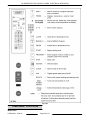
DIAGNOSTIC DISPLAY EXAMPLES
NOTE: Remove tube from chemical cleaner bottle
before starting procedure to keep excess chemical
from entering machine during test.
NOTE: The grey water/sump peristaltic pump was
removed from machines with Serial No. 46300096
and higher.
1.
Enter SERVICE MODE - PROGRAMMING AND
DIAGNOSTICS. Use the keypad to enter
parameter numbers.
Operation
8
VFD Display - Current
Software Version (C027)
A.
Press CLEAN key to enter clean mode.
Disregard error messages.
B.
Cavity light should be ON to indicate the
oven is in demo mode. If light is not on,
repeat procedure to enter DEMO MODE.
NOTE: As you press ENTER to advance through the
clean cycle operation, there may be short delays
before the cycle begins. You can pause the cycle at
any time by pressing the rotate switch or opening the
door.
VFD Display - Previous
Software Version (dA09)
Verify Functionality
•
Cavity light ON
NORMAL WASH MODE
CLEANING
•
Rotor turning
PREHEATING
PREHEATING
•
Heaters ON
If correct, press ENTER.
9
•
Grease pump ON
NORMAL WASH MODE
CLEANING
•
Rotor stops
DRAINING GREASE
DRAINING GREASE
•
Heaters OFF
If correct, press ENTER.
10
NORMAL WASH MODE
CLEANING
WATER FILL
WATER FILL
Page 41 of 72
If correct, allow water to fill up to the
water level probe. When water level is
satisfied, it will automatically roll to the
next step.
F25294 Rev. A (0412)
KA SERIES ELECTRIC ROTARY OVENS - SERVICE PROCEDURES AND ADJUSTMENTS
Operation
11
12
VFD Display - Current
Software Version (C027)
VFD Display - Previous
Software Version (dA09)
NORMAL WASH MODE
CLEANING
DEGREASE #1
DEGREASE #1
NORMAL WASH MODE
CLEANING
WATER DRAIN
WATER DRAIN
13
14
15
---
CLEANING
WATER DRAIN
NORMAL WASH MODE
CLEANING
WATER FILL
WATER FILL
NORMAL WASH MODE
CLEANING
ADDING DETERGENT
ADDING DETERGENT
Verify Functionality
If the machine is washing (wash arm
spinning), press ENTER.
If the machine is draining water, press
ENTER.
If installed, the grey water/sump
peristaltic pump should be running.
If correct, press ENTER.
If correct, allow water to fill up to water
level probe. When satisfied it will
automatically roll to the next step.
•
Chemical pump ON
•
Verify pump is pulling chemical.
See Clean Cycle Troubleshooting
(KA7E Only) as necessary.
If correct, press ENTER.
NORMAL WASH MODE
16
WASHING
CLEANING
NORMAL WASH MODE
WASHING
SOAKING
17
NORMAL WASH MODE
CLEANING
WATER DRAIN
WATER DRAIN
18
19
20
21
---
WATER DRAIN
NORMAL WASH MODE
CLEANING
WATER FILL
WATER FILL
NORMAL WASH MODE
CLEANING
RINSE #1
RINSE #1
NORMAL WASH MODE
CLEANING
WATER DRAIN
WATER DRAIN
22
23
CLEANING
---
CLEANING
WATER DRAIN
NORMAL WASH MODE
CLEANING
WATER FILL
WATER FILL
F25294 Rev. A (0412)
Page 42 of 72
If the machine is washing (wash arm
spinning), press ENTER.
NOTE: Total cycle time is 2 hrs (timer
counts down). Washing/ soaking
alternates every 4 min during the cycle.
•
Drain pump ON
•
Rotor stop
If correct, press ENTER.
If installed, the grey water/sump
peristaltic pump should be running.
If correct, press ENTER.
If correct, allow water to fill up to water
level probe. When satisfied it will
automatically roll to the next step.
•
Wash arm spraying
•
Rotor turning
If correct, press ENTER.
•
Drain pump ON
•
Rotor stop
If correct, press ENTER.
If installed, the grey water/sump
peristaltic pump should be running.
If correct, press ENTER.
If correct, allow water to fill up to water
level probe. When satisfied it will
automatically roll to the next step.
KA SERIES ELECTRIC ROTARY OVENS - SERVICE PROCEDURES AND ADJUSTMENTS
Operation
24
25
VFD Display - Current
Software Version (C027)
VFD Display - Previous
Software Version (dA09)
NORMAL WASH MODE
CLEANING
RINSE #2
RINSE #2
NORMAL WASH MODE
CLEANING
WATER DRAIN
WATER DRAIN
26
27
---
WATER DRAIN
CLEANING
DRYING
DRYING
•
Wash arm spraying
•
Rotor turning
If correct, press ENTER.
CLEANING
NORMAL WASH MODE
Verify Functionality
If correct, allow the water to drain
completely from the machine. It will
automatically roll to the next step.
If installed, the grey water/sump
peristaltic pump should be running.
Allow the pump to remove the water. It
will automatically roll to the next step
after 2 minutes.
•
Heaters ON
•
Rotor turning
If correct, press ENTER.
PRESS START OR CLEAN
28
CLEAN CYCLE
COMPLETE
CLEAN CYCLE
COMPLETE
Done. The machine will automatically
exit CLEANING and go to IDLE.
Select program 0-9
Return to Normal Mode
1.
Enter SERVICE MODE - PROGRAMMING AND
DIAGNOSTICS. Use the keypad to enter
parameter numbers.
2.
If current software version C027, continue to step
4.
3.
If previous software version dA09, press 72 and
select ENTER (parameter to unlock service only
parameters.
A.
Press 1972 and select ENTER (code to
unlock service only parameters) (1 beep).
TEMPERATURE SENSOR TEST
Disconnect the
electrical power to the machine and
follow lockout / tagout procedures.
1.
Remove Right Side Cover.
2.
Remove the probe lead wires from the CPU
board.
3.
Test the probe with an ohmmeter.
4.
Press 44 and select ENTER (allows selection of
DEMO/NORMAL Mode parameter).
5.
Press 0 and select ENTER (sets machine to
NORMAL MODE).
60
530
70
541
6.
Turn power switch OFF (save settings and exit
service mode).
80
552
7.
Turn power switch ON. Oven is now operating in
normal mode and is idle.
90
563
100
573
125
600
150
627
200
680
250
732
300
785
A.
B.
Cavity light should be OFF to indicate the
oven is in normal mode. If light is not off,
repeat procedure to enter NORMAL MODE.
Install tube back into chemical cleaner
bottle.
TEMPERATURE in °F
Page 43 of 72
RESISTANCE ±5 OHMS
F25294 Rev. A (0412)
KA SERIES ELECTRIC ROTARY OVENS - SERVICE PROCEDURES AND ADJUSTMENTS
TEMPERATURE in °F
RESISTANCE ±5 OHMS
350
836
400
887
450
938
3.
Record the temperature tester readout for an
additional 3 cycles. It should cycle around a set
point.
4.
Calculate the amplitude. Amplitude = (Turn Off Turn On). An amplitude of more than 40 degrees
may indicate a failed element. See heating
element test.
5.
Calculate the average. Actual average = (Turn
On + Turn Off ) divided by 2. Variance (between
actual average and programmed set point) of
greater than 5 degrees indicates that adjustment
is needed.
6.
To adjust:
HEATING ELEMENT TEST
Disconnect the
electrical power to the machine and
follow lockout / tagout procedures.
MODEL
WATTAGE/
VOLTAGE
2500/208
18
2500/240
24
KA7EM 3000/208
16
3000/240
21
KA7E,
A.
RESISTANCE*
NOTE: The P key is used to toggle the minus sign on
and off. Use this key if a negative value must be
entered.
B.
If the actual average temperature is higher
than the programmed set point, then enter
a positive offset value of the same amount.
(For example if the oven is cycling around
an actual average of 360 degrees, adjust by
entering an offset of +10.)
C.
If the actual average temperature is lower
than the programmed set point, then enter
a negative offset value of the same amount.
(For example if the oven is cycling around
an actual average of 340 degrees, adjust by
entering an offset of -10.)
*Tolerance +5 / -10 %.
PUMP, K3 RELAY COIL TESTS
Disconnect the
electrical power to the machine and
follow lockout / tagout procedures.
MODEL
PUMP
Enter SERVICE MODE - PROGRAMMING
AND DIAGNOSTICS, enter parameter
number 5 Temperature Offset.
RESISTANCE ±5 OHMS
1)
The offset can be adjusted + or - 30 deg
F, but is only functional within the
operating limits of the oven. Factory
setting is 0.
KA7E
Drain
87
KA7E
Wash
32
KA7E,
KA7EM*
Grease
14
Peristaltic
7.
To save the setting, press the enter key.
KA7E
K3
8.
Turn the power switch to off and then on again.
The oven will remember the changes.
9.
To recall the offset value, enter SERVICE MODE
- PROGRAMMING AND DIAGNOSTICS, enter
parameter number 5 Temperature Offset. Verify
that the value you set is visible on the time
display.
190
*Models with grease assist option only.
CONTROLS CALIBRATION
Calibration Procedure
NOTE: See Table 12 at the end of this procedure.
1.
Place temperature tester probe in the geometric
center of oven cavity.
2.
Program a set point of 350 degrees. Allow oven
temperature to cycle 3 times. Oven display
temperature reading should equal the set point of
350 degrees.
F25294 Rev. A (0412)
Page 44 of 72
KA SERIES ELECTRIC ROTARY OVENS - SERVICE PROCEDURES AND ADJUSTMENTS
Temperature Data Recording Table
Temperature Tester
Heater Turn on
Actual Average
(Turn On + Turn Off)
divide by 2
Temperature Tester
Heater Turn off
________
________
________
________
________
________
________
________
________
Page 45 of 72
F25294 Rev. A (0412)
KA SERIES ELECTRIC ROTARY OVENS - ELECTRICAL OPERATION
ELECTRICAL OPERATION
COMPONENT FUNCTION
Power Switch . . . . . . . . .
Controls power to control circuits.
High Limit Thermostat . . .Prevents oven from exceeding 482°F ±12 °F if controls malfunction.
Wash Pump M1
(KA7E) . . . . . . . . . . . . . . . .
Circulates water and detergent during wash cycle.
Drain Pump M2 . . . . . . .
Empties water from oven when turned on.
Rotisserie Motor M3 . . .
Turns the rotisserie.
Blower Motors M4, M5 . . . Circulates air inside oven cavity.
Grey Water/Sump
Pump M6 (KA7E) . . . . .
Empties remaining water from sump area. Removed from ovens with Serial No.
46300096 and higher
Grease Pump M7 . . . . .
Empties grease accumulated in sump prior to wash cycle. KA7EM models with grease
assist only.
Chemical Pump M8
(KA7E) . . . . . . . . . . . . . . . .
Dispenses predetermined amount of detergent for wash cycle.
Water Fill Valve S1
(KA7E) . . . . . . . . . . . . . . . .
Is turned on to fill oven with fresh water for wash and rinse cycles.
Water Level Control
Board (KA7E) . . . . . . . . .
Monitors input from water level sensor and chemical sensor.
CPU Board . . . . . . . . . . . .
Allows input from keypad, controls oven functions.
Contactor K1 . . . . . . . . .
Power to oven heat elements. Controlled by CPU board.
Contactor K2 . . . . . . . . .
Supplies power to oven heat elements and controlled by power switch and by high limit
thermostat.
Relay K3 (KA7E) . . . . . .
Monitors door interlock switches and provides power to wash pump.
Light (internal) . . . . . . . .
Provides light for inside oven.
Temperature Sensor . . . Senses temperature of oven cavity for the CPU control.
Display Board . . . . . . . .
Shows time and temperature; also contains keypad for programming CPU board.
Rotisserie Motor
Capacitor C1 . . . . . . . . . .
Start capacitor for rotisserie motor.
Blower Motor
Capacitors C2, C3 . . . .
Run capacitors for blower motors M2, M3.
SEQUENCE OF OPERATION
A.
Oven connected to correct supply voltage
and is properly grounded.
Refer to Model KA7E Schematic Sheet 1 and Sheet 2
for the electrical sequence of operation. The letter "P"
followed by a 2 digit number refers to the Program
Item Number in SERVICE MODE - PROGRAMMING
AND DIAGNOSTICS.
B.
Control board is powered and LED on board
is flashing to indicate power is applied.
Programmed Cooking
1.
Conditions
F25294 Rev. A (0412)
NOTE: Control board is powered and neutral is
applied to the oven component circuitry when supply
voltage is connected to the oven. The power switch
controls power for the oven to operate, not power to
the oven.
C.
Page 46 of 72
Power switch is off.
KA SERIES ELECTRIC ROTARY OVENS - ELECTRICAL OPERATION
2.
D.
High limit thermostat is set to maximum and
contacts are closed.
E.
Oven cavity is at room temperature.
CPU board internal relay CR4 opens.
Power removed from K1 contactor coil.
a.
Power switch indicator light on.
B.
Power supplied to K2 coil thru power switch
contacts and high limit thermostat contacts.
7.
K2 contacts close.
C.
Display shows time and the last operated
program number.
D.
Step LEDs may be on if a program is
selected.
E.
Oven is in idle mode.
Select a saved cook program (press numbered
keys 1 thru 9).
Any programed step LEDs for the selected
program are illuminated.
Press Start to run cook cycle.
A.
Power applied to rotisserie motor (M3) thru
internal relay CR3 on CPU board.
B.
Power applied to blower motors M4 and M5
thru internal relay CR2 on CPU board.
Power removed from heater
elements E1, E2 and E3.
Oven continues to cycle until time expires and
beeper sounds; or add 5 min button is pressed;
or stop button is pressed.
A.
Press beeper silence button to silence
beeper.
8.
At the end of cook cycle, all power is removed
from M3, M4, M5, E1, E2, and E3.
9.
Press Start to run the selected program again, or
select a different program to run.
Washing Cycle Sequence of Operations
NOTE: Auto clean oven's - the grease pump cycles
on/off depending on the times entered in service
mode.
NOTE: The grey water/sump peristaltic pump was
removed from machines with Serial No. 46300096
and higher.
Criteria for starting wash cycle:
1.
Power switch must be ON.
C.
Power applied to light thru internal relay
CR1 on CPU board.
2.
Machine must be in idle mode (not in a cooking
mode).
D.
Power applied to heat element contactor K1
coil thru internal relay CR4 on CPU board
and power switch contacts.
3.
Cavity temperature must be less than the
programmed setting P41. Factory default is set
at 250°F (recommended).
1)
K1 contacts close.
A.
2)
Power applied to heat elements E1,
E2, and E3 thru K1 closed contacts and
K2 closed contacts.
E.
Display shows the number of the program
running.
F.
Step LED for the cook step in progress will
blink.
G.
Cook temperature for the cook step in
progress will display.
H.
5.
A.
1)
A.
A.
4.
Cavity reaches programmed set temperature.
Power switch is turned on.
1)
3.
6.
If the temperature is above this setting when
the clean button is pressed, the unit goes
into cool down mode until temp goes down
to programmed setting P41or below.
4.
All spits and accessories are removed from
interior of cavity.
5.
No soft metals (i.e. Aluminum foil) are inside the
machine.
User Presses CLEAN Button
1.
Preheat mode: Oven goes into pre-heat cooking
mode with a temperature programmed set point
in P42. The machine remains in preheat mode for
the number of minutes programmed in P32.
2.
Drain Grease: The grease pump comes ON for
the number of minutes programmed in P30.
3.
Pre-rinse: Factory default is 1 pre-rinse.
However, multiple pre-rinses are programmable
in P37.
Total combined cook time for all steps in
the selected program will be displayed and
will count down.
Temperature sensor senses oven cavity
temperature.
NOTE: High limit thermostat must be set to maximum
otherwise thermostat could regulate cavity
temperature.
Page 47 of 72
F25294 Rev. A (0412)
KA SERIES ELECTRIC ROTARY OVENS - ELECTRICAL OPERATION
4.
Water is injected into the sump until level reaches
probe. This "fill time" will then be used for all
subsequent fill cycles.
16. Wash cycle complete.
17. Post-rinse: The number of post-rinse cycles is
factory set at 2. (can be programmed in P35)
5.
Once water is sensed at the probe, the wash
pump turns ON and rinsing begins. This normally
lasts for 2 minutes. (can be programmed by P36)
18. Fill sump with water based on "fill time"
determined by Pre-Rinse.
6.
After rinsing is complete, the drain pump turns
ON for 3 minutes. (can be programmed by P33)
19. After filling with water, the wash pump turns ON
and washing begins. This normally lasts for 2
minutes.
7.
After drain pump is complete, the drain peristaltic
turns ON for 3 minutes (if installed on machine).
8.
Cycle now complete.
9.
Wash: Now the machine is ready to wash.
20. After rinsing is complete, the drain pump turns
ON for 3 minutes.
21. After drain pump is complete, the drain peristaltic
turns ON for 3 minutes (if installed on machine).
10. Fill sump with water based on "fill time"
determined during Pre-Rinse.
22. Cycle now complete.
11. Chemical injected for 40 seconds. (can be
reprogrammed in P31)
23. Drying Mode: After the post rinse cycles are
complete, the software enters the Drying Mode
for 10 minutes.
12. Begin washing. Wash pump ON for 4 minutes
(can be reprogrammed in P48) and OFF for 4
minutes (can be reprogrammed in P49).
24. The machine heats to 250°F (can be
programmed by P43). If drying time is set to 0,
the drying mode is skipped.
13. Washing lasts for 120 minutes. (can be
reprogrammed in P34)
25. Cleaning is complete.
14. After washing is complete, the drain pump turns
ON for 3 minutes. (can be programmed in P33)
15. After drain pump is complete, the drain peristaltic
turns ON for 3 minutes (if installed on machine).
(can be programmed in P33)
F25294 Rev. A (0412)
CONTROLS EXPLANATION
Model KA7E
Page 48 of 72
KA SERIES ELECTRIC ROTARY OVENS - ELECTRICAL OPERATION
Fig. 122
Model KA7EM
Page 49 of 72
F25294 Rev. A (0412)
KA SERIES ELECTRIC ROTARY OVENS - ELECTRICAL OPERATION
Fig. 123
COMPONENT LOCATIONS
Model KA7E
F25294 Rev. A (0412)
Page 50 of 72
KA SERIES ELECTRIC ROTARY OVENS - ELECTRICAL OPERATION
Fig. 124
KA7E - Component Name
A . . . . . . . . . . . . . . . . . . . . . . Fan, motors and blade assembly M4 and M5
B ......................
Heat elements (two 3000W E1 and E3, one 2500W E2)
C ......................
Temperature sensor
D ......................
TB3 terminal block
E ......................
TB2 terminal block
F ......................
Capacitor C1 for drive motor M3
G ......................
Water level control board
H ......................
Capacitors C2 and C3 for fan motors M4 and M5
I .......................
CPU board
J ......................
Heat element contactors K1 and K2
Page 51 of 72
F25294 Rev. A (0412)
KA SERIES ELECTRIC ROTARY OVENS - ELECTRICAL OPERATION
K ......................
Transformer supplies 24V to CPU board
L ......................
K3 door interlock relay
M .....................
TB1 terminal strip
N ......................
High limit thermostat
O ......................
TB6 power in terminal block
P ......................
Drive motor assembly M3
Q ......................
Grey Water/Sump pump M6. Removed from ovens with Serial No. 46300096 and higher.
NOTE: TB4 terminal strip located above and behind pumps.
R ......................
Grease pump M7
S ......................
Chemical pump M8
T ......................
Chemical sensor (not shown)
U ......................
Water fill S1
V ......................
Utility plate
W .....................
Wash pump M1
X ......................
Drain manifold
Y ......................
Drain pump M2
1 ......................
Snooze switch
2 ......................
Silence buzzer switch
3 ......................
Stop switch
4 .....................
Rotate switches
5 .....................
Overlay with switch instructions
6 ......................
Keypad and display board assembly
7 ......................
Power switch
8 ......................
Meat probe mini jack
Model KA7EM
F25294 Rev. A (0412)
Page 52 of 72
KA SERIES ELECTRIC ROTARY OVENS - ELECTRICAL OPERATION
Fig. 125
KA7EM - Component Name
A . . . . . . . . . . . . . . . . . . . . . . Fan, motors and blade assembly M4 and M5
B ......................
Heat elements (two 3000W E1 and E3, one 2500W E2)
C ......................
Temperature sensor
D ......................
Capacitor C1 for drive motor M3
E ......................
Capacitors C2 and C3 for fan motors M4 and M5
F ......................
CPU board
G ......................
Heat element contactors K1 and K2
H ......................
Transformer supplies 24V to CPU board
I .......................
TB1 terminal strip
J ......................
High limit thermostat
Page 53 of 72
F25294 Rev. A (0412)
KA SERIES ELECTRIC ROTARY OVENS - ELECTRICAL OPERATION
K ......................
TB2 power in terminal block
L ......................
Drive motor assembly M3
M .....................
Utility plate (for grease assist option)
N ......................
Electrical Connection (E1)
O ......................
Grease Assist, Pumped Drain (P2)
P ......................
Drain (main & sump) (P1)
Q ......................
TB3 terminal strip located above and behind pump.
R ......................
Grease Pump - Models with grease assist only.
S ......................
Sump Drain Level, Manual
1 ......................
Keypad and display board assembly
2 ......................
Rotate switches
3 ......................
Power switch
4 ......................
Meat probe mini jack
WIRING DIAGRAMS
KA7E - Component Connections
F25294 Rev. A (0412)
Page 54 of 72
KA SERIES ELECTRIC ROTARY OVENS - ELECTRICAL OPERATION
Fig. 126
KA7EM - Component Connections
Page 55 of 72
F25294 Rev. A (0412)
KA SERIES ELECTRIC ROTARY OVENS - ELECTRICAL OPERATION
Fig. 127
Power Connection
F25294 Rev. A (0412)
Page 56 of 72
KA SERIES ELECTRIC ROTARY OVENS - ELECTRICAL OPERATION
Fig. 128
SCHEMATIC DIAGRAMS
Model KA7E
Page 57 of 72
F25294 Rev. A (0412)
KA SERIES ELECTRIC ROTARY OVENS - ELECTRICAL OPERATION
Fig. 129
F25294 Rev. A (0412)
Page 58 of 72
KA SERIES ELECTRIC ROTARY OVENS - ELECTRICAL OPERATION
Fig. 130
Model KA7EM
Page 59 of 72
F25294 Rev. A (0412)
KA SERIES ELECTRIC ROTARY OVENS - ELECTRICAL OPERATION
Fig. 131
F25294 Rev. A (0412)
Page 60 of 72
KA SERIES ELECTRIC ROTARY OVENS - ELECTRICAL OPERATION
Fig. 132
Page 61 of 72
F25294 Rev. A (0412)
KA SERIES ELECTRIC ROTARY OVENS - ELECTRICAL OPERATION
PLUMBING DIAGRAMS (KA7E
ONLY)
Fig. 133
F25294 Rev. A (0412)
Page 62 of 72
KA SERIES ELECTRIC ROTARY OVENS - ELECTRICAL OPERATION
Fig. 134
Page 63 of 72
F25294 Rev. A (0412)
KA SERIES ELECTRIC ROTARY OVENS - TROUBLESHOOTING
TROUBLESHOOTING
diagnostic tests the service technician can quickly and
easily determine if a component is functioning
properly or in need of repair.
Troubleshooting
Before performing any of the troubleshooting checks
listed below, use the SERVICE MODE PROGRAMMING AND DIAGNOSTICS to assist in
diagnosing the problem. By utilizing the oven controls
NOTE: Ensure wiring and board connections are tight
and secure; and board connectors are inserted
properly (not misaligned).
General Troubleshooting (KA7E & KA7EM)
SYMPTOM
POSSIBLE CAUSES
TSB 1417 KA7E - CLOGGING AT INPUT AND OUTPUT
Clogging at input and output of peristaltic pumps (KA7E
OF PERISTALTIC PUMPS. See Multimedia section in
and KA7EM with grease assist only)
TIS.
TSB 1381 KA7E ROTARY OVEN SCRAMBLED VFD
DISPLAY.
Scrambled VFD display (KA7E only)
1.
Wired incorrectly.
2.
Power switch malfunction.
1.
Main breaker open.
2.
Power switch malfunction.
3.
Wired incorrectly.
1.
Oven wired incorrectly.
2.
Heat element shorted.
3.
Wiring shorted.
Rotor does not turn.
1.
See TROUBLESHOOT ROTOR COMPONENTS.
TSI: HR7E AND KA7E ROTISSERIE OVEN ROTOR
CRANK ARM DISENGAGING FROM ROTOR. See
Multimedia section in TIS.
2.
Control board malfunction. Test in P22.
3.
Crank arm pins sheared.
1.
Blower motor malfunction. Test in P22.
2.
Blower motor capacitor malfunction.
3.
Control board malfunction.
1.
Incorrect line voltage.
2.
Heat element malfunction.
3.
High limit thermostat not set to maximum position.
4.
Blower motors malfunction. Test in P22.
5.
Blower motor capacitor malfunction.
6.
Temperature sensor malfunction.
7.
Oven out of calibration.
8.
Control board malfunction.
Power switch internal indicator light not on but oven
operates.
No power to oven controls.
Main breaker will trip.
Blower motor does not run when cooking.
Oven temperature does not reach desired temperature
or takes a longer time to heat-up and recover.
F25294 Rev. A (0412)
Page 64 of 72
KA SERIES ELECTRIC ROTARY OVENS - TROUBLESHOOTING
General Troubleshooting (KA7E & KA7EM)
SYMPTOM
POSSIBLE CAUSES
No heat, but blowers, rotor and customer lamp do
operate when oven cavity is below set temperature.
No display and/or keypad does not function.
Slow cooking.
1.
High limit thermostat open.
2.
K1 contactor malfunction.
3.
K2 contactor malfunction.
4.
Control board malfunction.
1.
Display cable connection loose.
2.
Keypad connection at display circuit board loose.
3.
Bad ribbon cable.
4.
Keypad malfunction.
5.
Display circuit board malfunction.
6.
Control board malfunction.
1.
Fan cover not installed correctly.
2.
Clean oven fans.
3.
Blower motor(s) malfunction. Test in P22.
Clean Cycle Troubleshooting (KA7E Only)
NOTE: Durning a cleaning cycle, pauses of several seconds may occur as the oven cycles from one mode of
cleaning to another mode. This is normal and should not be considered a problem.
SYMPTOM
POSSIBLE CAUSES
TSB1400 KA7E - LEAKS AT DRIVE ARM GASKET
DURING WASH CYCLE.
Leaks into control area at drive arm.
Water is not spraying during wash cycle.
Wash arm is not turning.
Nothing seems to be happening after CLEAN is pressed.
1.
Wash cycle is in soak mode. Display shows
Soaking.
1.
Strainer pans are not installed correctly and are
interfering with wash arm motion.
1.
Oven is cooling down or preheating to the optimum
temperature for cleaning.
1.
Chemical bottle may be empty.
2.
Ensure tubing is cut at an angle and that standpipe
is in place to prevent tube from curling inside
chemical bottle.
3.
Water not hot enough.
4.
May need additional pre-rinse programmed (P37).
1.
Water not hot enough.
2.
Add second pre-rinse to prime hot water line (P37).
3.
Make sure washer arm is not plugged. Remove all
debris if necessary.
4.
Increase wash pump duty cycle (P48).
5.
Increase amount of chemical being used (P31).
Oven is not clean enough after clean cycle is complete.
Too much foam or white residue left after clean cycle.
Page 65 of 72
F25294 Rev. A (0412)
KA SERIES ELECTRIC ROTARY OVENS - TROUBLESHOOTING
Clean Cycle Troubleshooting (KA7E Only)
Nothing seems to be happening in clean mode.
Oven uses too much chemical.
Grease or liquids running outside of oven.
Chemical pump not pulling chemical cleaner.
1.
Time delays are programmed between steps during
clean cycle. This is normal operation.
1.
Typical usage is approximately 1/2 gallon per day.
Contact Product Service.
1.
Pump tubing needs to be replaced.
1.
Chemical bottle may be empty.
2.
Ensure tubing is cut at an angle and that standpipe
is in place to prevent tube from curling inside
chemical bottle.
3.
Check chemical pump ON time (P31).
4.
Clog inside hose inlet or outlet.
5.
Hose leaking or air gaps at connections.
6.
Pump not receiving power or malfunction.
7.
Control board malfunction.
Clean Cycle Troubleshooting - Error Messages (KA7E Only)
Display Shows
When Displayed
ERROR 1
CHECK DETERGENT
OR
CHECK DETERGENT
Cause
1.
Insufficient liquid level in
cleaning agent bottle.
2.
Pick up tube not submerged in
cleaner. Ensure tubing is cut at
an angle and that standpipe is in
place to prevent tube from
curling inside chemical bottle.
3.
Defective hose (broken,
squeezed closed).
4.
Chemical pump or control not
working. Test in P22.
1.
Oven drain plugged/not flowing.
2.
Drain pump plugged.
3.
Drain pump fails to operate or
control not working. Test in P22.
When cleaning agent flow from
container into sump is not detected by
sensor.
CHECK DETER PUMP
ERROR 2
PRESS STOP
OR
ATTEMPTING TO
DRAIN SUMP
When there is water in the sump at
the start of a clean cycle.
DRAIN FAIL
CHECK DRAIN, PUMP
F25294 Rev. A (0412)
Page 66 of 72
KA SERIES ELECTRIC ROTARY OVENS - TROUBLESHOOTING
Clean Cycle Troubleshooting - Error Messages (KA7E Only)
Display Shows
When Displayed
Cause
ERROR 3
1.
Main water supply turned off.
PRESS STOP
2.
Supply hose disconnected or
kinked.
3.
Water pressure too low.
4.
Oven fill valve or control not
working. Test in P22.
5.
Unit draining as it fills. Test in
P22.
1.
Door left open when it should be
closed.
2.
Door closed position sensor or
control not working. Test in P23.
OR
CANNOT CONTINUE
CLEANING CYCLE
When no or insufficient water is
coming into oven.
WATER FAIL
CHECK SUPPLY
DOOR IS OPEN
CLOSE THE DOOR
NORMAL WASH MODE
OR
CLEANING
CYCLE PAUSED
CYCLE
STOPPED
WASH MODE
CANCELLED
OR
CLEANING
CANCELLED
INTERRUPTED
CLEAN CYCLE
When door needs closed during
certain steps of the program.
Displays when Pause (Rotate) button
is pressed during cleaning cycle.
Returns to and displays step of cycle
that was paused when Pause button
is pressed and released, or when
door is closed or opened and closed.
---
Displays for 5 seconds when STOP
key pressed during clean cycle up to
and through DRAINING GREASE, or
when STOP key is pressed during a
cook time.
---
Displays when STOP key is pressed
during cleaning cycle including and
after the CLEANING WATER FILL
step for the pre-rinse. Please wait
while oven cycles through two rinse
cycles and the drying cycle.
---
Displays when clean cycle
interrupted by cycling power off and
back on. Please wait while oven
cycles through two rinse cycles and
the drying cycle.
---
TROUBLESHOOT ROTOR
COMPONENTS
1.
1)
Verify motor shaft rotation as viewed
from end of shaft. Rotation must be
clockwise. If rotation is
counterclockwise, replace capacitor. If
motor shaft rotates correctly, continue
to step D.
2)
If motor does not operate.
If drive hub on gear box does not turn:
A.
Remove four screws securing rotor drive
motor and speed reducer to gearbox.
B.
Lift motor off speed reducer and support it.
C.
Press the rotate switch.
a.
Does relay on control board
operate?
Yes = replace motor and/or motor
capacitor.
Page 67 of 72
F25294 Rev. A (0412)
KA SERIES ELECTRIC ROTARY OVENS - TROUBLESHOOTING
No = replace control board.
b.
Assemble oven and check
operation.
D.
Lift speed reducer off gearbox.
E.
Insert at least two motor mounting screws
into motor flange and mate speed reducer
to motor. Hold the assembly while pressing
the rotate switch.
F.
1)
If output shaft on speed reducer
rotates, continue to step F.
2)
If output shaft on speed reducer does
not rotate and motor is running, replace
speed reducer. Assemble oven and
check operation.
Manually rotate gearbox shaft which mates
with speed reducer to verify gearbox
function.
1)
If crank arm does not rotate or worm
gear cannot be rotated, replace
gearbox. Assemble oven and check
operation.
2)
If crank arm does rotate, recheck
previous steps to identify malfunction.
F25294 Rev. A (0412)
Page 68 of 72
KA SERIES ELECTRIC ROTARY OVENS - APPENDIX
APPENDIX
REVERSING CONTROLS
Disconnect the
electrical power to the machine and
follow lockout / tagout procedures.
NOTE: Rotor on/off switch position does not get
changed.
1.
Remove Right Side Cover.
2.
Disconnect wires from power switch.
3.
Squeeze tabs on bezel and pull switch and bezel
out of hole.
Fig. 136
5.
Remove six nuts securing display panel with
display board attached and lift out of oven.
Fig. 135
4.
Unplug ribbon cable from display board.
A.
Spread retaining clips to extract plug from
socket.
Page 69 of 72
Fig. 137
F25294 Rev. A (0412)
KA SERIES ELECTRIC ROTARY OVENS - APPENDIX
Fig. 140
Fig. 138
6.
7.
Identify and disconnect wires from mini jack
terminals.
8.
KA7E only:
Remove mini jack from front panel.
A.
Use a small screwdriver or similar object to
carefully pry tabs out and work retainer clip
off jack.
Fig. 139
NOTE: Jack shown removed from oven for view. Also
notice that wires are polarity sensitive and must be
connected properly for correct operation.
F25294 Rev. A (0412)
Page 70 of 72
A.
On opposite side of oven, identify and
remove wires from momentary switches.
B.
Remove six nuts securing momentary
switch plate and work the plate from the
oven.
C.
Remove two nuts securing the auto clean
overlay plate and its retaining plate.
D.
Install momentary switch plate and auto
clean overlay plate on the opposite side of
oven.
KA SERIES ELECTRIC ROTARY OVENS - APPENDIX
Fig. 141
9.
KA7EM only:
MODEL KA7EM
A.
On the opposite side of oven, remove six
nuts securing the blank switch cover plate
and work the plate from oven.
D.
B.
Remove two nuts securing blank overlay
cover plate and its retaining plate.
From front of oven, remove drain handle
from the drain control linkage assembly
(manual grease/sump drain).
E.
C.
Install the blank switch cover plate and
blank overlay cover plate on the opposite
side of where removed.
Remove drain control linkage assembly
from drain valve and work from oven.
Page 71 of 72
1)
Remove drain control lever from
linkage assembly.
2)
Re-install drain control lever near the
end of linkage assembly. See picture
23921 below.
3)
Remove bushing from the front of
oven.
F25294 Rev. A (0412)
KA SERIES ELECTRIC ROTARY OVENS - APPENDIX
Fig. 143
F.
From rear of oven, remove plug and reinstall on the opposite side of where
removed.
1)
Fig. 145
10. Install power switch on the opposite side of where
removed.
Install bushing in-place of plug.
11. Install display panel with display board on the
opposite side of where removed.
12. Cut cable ties as necessary and route wires to
their appropriate parts then reconnect.
13. Route ribbon cable to display board and
reconnect.
14. Install new cable ties as needed to neatly dress
wires out of the way.
15. Install covers and check for proper operation.
Fig. 144
2)
Insert threaded end of drain control
linkage assembly through bushing.
3)
Install drain control lever to drain valve.
Secure with mounting nut.
F25294 Rev. A (0412)
Page 72 of 72