1
MANUAL NO. 448R
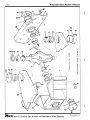
MODEL SELF PROPELLED
VIBRATORY ROLLER
(R 870)
SERVICE MANUAL.
1
la
r44 Etor • • • • • • • • • • • • • • • • • • • • • • • • • • • • • • • • arxif eATja uoT4ovay
e
IT '5' g - a118##.
• • • • • • • • • • • • • • • • • • .0 • • .• • • • • .• •s4ouipv'
a .Tun istabiod
• • • • • • • • • • • • • • • • • • • • • • • • • • • .. • • • sajTja Di stoat/14
• •• • • • • • •• • ••• • OOOOO • • • • • • • • • • ttou s aol:sacITA
•••••••••••quTor SuT4rTnoT4.11/ - euread LIGIT 0 11
. OOOOO . jtaa44 .sa 4aE4S aetT4ram pToo n TruoT4do
OOOOO aursaa trrsw
arT4t/s Tri
4uatuna;su,
4tiamna4sui
O
Ta ems m V uoT4ona4suI
....................... OOOOO saa dvaosoursag
10. 0 OO
••
OOOOO stoa4u03
snoaurrposTW
Ea...u2.17 # fbooqooloOdroiDer
6a.-9E'-11e## "...."'"
-9zu tt oegolpeool000
Lz atr usmi
#
0 ,0•0 0 080. •
""eATaa ae4Toxa - attrrA SuTProtuft
GATaa uoT4oray
'"'ma4sRS 0TinvaPSH
OOOOO • chund 2t/Taaals
410 "5""wma4sSg oTTnrap.RH SuTaaa4s
Ao OOOOO aapuTt.R 0 arTaaaqs
oo .........,....4T un Toa4uo0 2uTaaeqs
004,00410016,41 4ro5lp0000lle, ,,
gE -tla
112.17 #
00 00 4, 4,w
OOOOO .dmna 0T4r4soap sH
...........
...........
0T4v4soapICH
TTa_oa_142tm
E _0E_u2tor
OOOOO
"wanTaa aavroxa - dwnd oTinraP 41.1
61_13T_I:12## OOOOO
""aATaCT Ja4Toxa - .10 4014 0 TireaPAH
.[..942 4 #
""'""'"Ille4ssS 0 TinvaPSH aa4Toxa
9
-
i_uetor
dpose050004,..
s4uauodwoo oTTnraPSH
oL6T `I +I pasTA*11
ug## 'ON mizalana
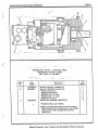
Always Give Serial Number of Machine
poor
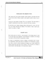
INSTRUCTIONS FOR ORDERING PARTS
Order repair parts from your Rex distributor. Specify quantity, part number and name of part.
Do not order by reference number or state quantity wanted in terms of sets or pairs.—
.
Always give serial number of machine. This is very important. The serial number is stamped
on manufacturers' plate which is attached to the frame of machine.
Be particular to give complete shipping address mentioning town, county, and state. Also
give billing instructions and address. Tell whether to ship gia parcel post, express, air
express, or freight.
DAMAGE CLAIMS
When broken goods are received, a full description of the damage should be made by the
carrier agent on the freight bill. If this description is insisted on, full damage can always
be collected from the transportation company.
We assume no responsibility for delay or damage to merchandise while in transit. Our responsibility ceases upon delivery of shipment to the transportation company, from whom a
receipt is received showing that shipment was in good condition and properly packed when
delivered, to them; therefore, claims for parts lost or broken in transit should be made
BY YOU to the transportation company.
Specify Quantity, Part Number and Description When Ordering
PII3
alma
Always Give Serial Number of Machine
448R-1
10
discrAff-
Ii
11
3
12
8
9
10
I-
ia
41111111w
13
O MI
0
„.•
17
18
0199
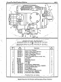
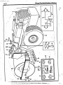
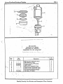
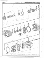
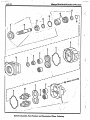
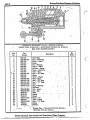
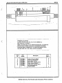
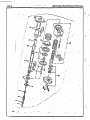
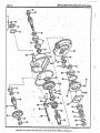
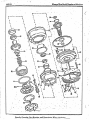
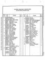
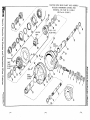
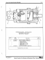
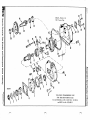
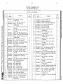
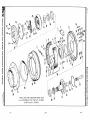
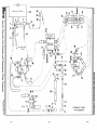
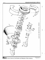
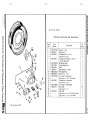
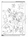
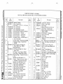
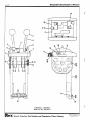
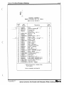
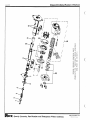
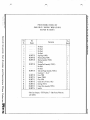
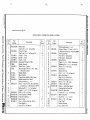
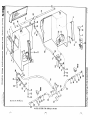
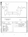
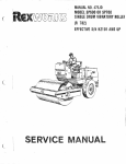
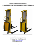
HYDROSTATIC PUMP —TRACTION DRIVE
SUNDSTRAND
MODEL NO. 22-2050 — REX PART NO. 102-7722-1
,-•
OR
SUNDSTRAND MODEL NO. 22-2052 — REX PART NO. 102-8346-1
1••• ••■••■■••
Item
No.
Part
Number
1
2
3
4
5
6
102-4365-4
102-4365-6
102-4365-7
102-4365-11
102-4365-12
102-4365-1
7
8
9
• 10
11
12
13
14
15
16
17
18
19
Description
*9210247
*9210248
*9220242
*9004102
*9004100-2340
102-4365-47
102-4355-5 2
102-4355-48
102-4365-49
102-4365-50
102:4365-51 . *
102-4365-24•
102-4365-46
.
Control Valve (*9800893) •
Gasket — Control Valve (*9800138)
Charge Pump (*9800629-04)
Gasket — Charge Pump (*9220327)
Check Valve (*9800648)•
Seal Kit (*9510022) Consists of Items 7 thru
11 Inclusive
Shaft Seal
Housing Seal Retainer
Seal Spring
"0" Ring
"0" Ring
Retaining Ring (*9006320-0025)
Charge Pump Relief Valve Poppet (*9800597)
Cotter Pin (*9004600-0607)
Pin (*9220441)
Washer (*9009610-2850)
"0" Ring (Orifice) (*9004101-0140)
Orifice (.042" Dia.) (*9800432)
Control Shaft Handle (*9800690)
No.
Req'd:
1
1
1
1
1
1
1
1
6
2
1
2
1
1
1
1
3
1
1
_*Sundstrand Corp. part numbers.
Specify Quantity, Part Number and Description When Ordering
••••
•
INF
•
•
• • Or • • • • ••• HI • ...ND ••••■ • ••
••• • • • • • • ••• • •••••••••• • •••••••
611.11,1.1“11 • ••• ■ ••••• 111111.11I MD MO ea .0 MD SD •1
• am. •••• •6* ••• ••• ■••• •••••• •■••• •••••• •••. . .
55
72
••• • • ••• • .•
• ■••••••••••• ••• ■••••• ••.•
64
•
a.
.•
... ...
50
ir
•1
.....
49.
75
76'
50:
.• •••• ..........
tip
-, 5
;•
3
'
42
71
4345 . 4i 4.
20
•
17
0
14 . ,63
26
'. 70 61ici
35
78 . 27 .3132 terS62
1
60
1211
•of.•
t!.1 0
241.
lk
;46
•
10
1)
25•".°4
4
58
•
48
•
•
• 56
6-2423
A---••25
66
. 39
Si
•
1111116( '
irralittY°
Ira ‘4:
'74
6537
•:
•
36
58 .•
•
384059
:•
41 .
•
IA •
.•
•
•
mown A T 10/SOC 0144)
15
8tirtrOP TA T 10
to.1
69
a-18
Item.Part
No.Number
1102-8358-1
•
*6K1-469
*5126687
Description
Diesel Engine — General Motors Corp.
Series 3-53 Model 5033-7201 with the
following features: (See Engine Parts
Book)
S.A.E. #4 Flywheel for use with
Rockford 11TT Clutch •
S.A.E. #4 Flywheel Housing
Governor — Variable Speed with Closed
Linkage set at 2400 F.L. and approx.
2600 N.L.
Fan - 18" Dia. Suction — 5 Blade
Fan Belt for Fan Mounted 12" above
Engine centerline
Air Inlet Housing for Remote Mounted
H.D. Air Cleaner
Lube Oil Filter, F.F. Mounted on Oil
Cooler
Exhaust Manifold, Center Vertical
Outlet
Water Connections less Radiator •
Connection
Battery Charging Generator 12 Volt
25 Amp.
Starting Motor 12 Volt (Sprag.)
Oil Pan, Shallow, For 10° Operation
Oil Pan Dipstick for 10° Pan
Breather on Flywheel Housing
Plain Rocker Cover with Oil Filler
on Side
Injectors, S45
Exhaust Outlet Flange — 3" Pipe Thds.
Oil Cooler — Engine only
C.S. Pulley — 2 Groove — Cone Driye
(*6K1A-153)
No.
Req'd.
Item
No.
Part
Number
102-7774-1
1
*5124405
*5186687
*5184255 •
*1110955
2502-4399-80
3
4
5
6
f
5 0 22:44 2 5 7 :88 10.,.
{102-3283-1
No.
Req'd.
Description
Diesel Engine (Coned.)
Tachometer Drive Mounted on R.H.
Balance Shaft when viewing Engine
from Flywheel End 90° Adapter —
1 to .500 Ratio giving a Cable Speed
of twice Engine Speed
Gasket — Air Inlet Housing
Name Plate (Emergency Shut-down)
Name Plate (Pull to Stop)
Voltage Regulator
Front Support — Engine
Cap Screw '4," x 1 1/4" with L.W.
Cap•Screw '4" x 1'4" with Nut & L.W.
Support — Rear (As Illustrated)
Support — Rear (Opposite of Must.)
11.C.-H.T. Cap screw 'A x 11/4" w/L.W.
Adapter — Flywheel
Nyloc Cap Screw '4" x 1" Socket Head
Drive Plate
Hub — Drive Plate
Drilled Cap Screw with %•" L.W.
Joint — Center Bonded
Drilled Cap Screw
Adapter Plate — Gear Pump
Cap Screw 14" x 1" with L.W.
Hydraulic Pump — Exciter Drive
(Commercial Shearing & Stamping
#P25X -178- BERS- 12- 7) (See
Separate Illustration)
Cap Screw 14" x 11/4" with L.W.
Bracket — Mount — Voltage Regulator
Cap Screw '4" x 1" with L.W.
Bracket — Steering Pump
Bracket — Steering Pump
Hex Nut & Cut Washer 14"
-
102-5164-1
402-624-4
102-7362-1
9
10
102-7361-1
111102-7360-1
1
{102-3666-1
. 12
7
• 8
102-7883-1
13
14
15
16
17
102-3694-1
502-2735-80
502-2736-80
2.
2.
1.
1:
4.
1
6
1
1
6
12
12
1
12
1
4
1
2
1
1
1
Alwa ys Give Serial Numberof Machine
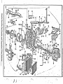
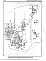
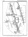
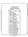
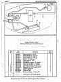
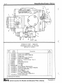
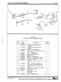
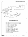
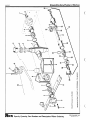
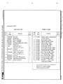
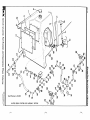
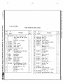
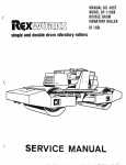
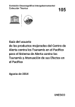
POWER UNIT AND ADJUNCTS
MUFFLER — AIR CLEANER — RADIATOR & HOSES
TRACTION AND EXCITER DRIVE HYDRAULIC PUMPS
POWER UNIT. AND ADJUNCTS •
MUFFLER — AIR CLEANER — RADIATOR & HOSES
TRACTION AND EXCITER DRIVE HYDRAULIC PUMPS• (Contd.)
t
00
70
4111111•••••••11111I .
Item
No.
18
19
20
21
22
23
24
25
26
27
28
29
'30
31
•32
33
34
35
Part
Number
{
102-7949-1
102-3675-1
298-7067-91
102-3680-1
298-5515-68
X203740
X203761
102-7036-1
X203765
X203741
298-41-93
102-7723-1
102-7725-1
502-4398-80
219
028-42072:17 1
• 38'
40
41
42
43
44
Screw '4" x 1" with LW, •
Cap Screw 14" x 1%" with L.W.
Hydraulic Pump (Steering) (Vickers
#VTM42-60-75-15-MD-R1-12) (See
Separate Illustration)
Sheave
"V" Belt (Maurey #3V375)
Adaptor — Flange Yoke
Nyloc Socket Head Cap Screw %," x 1"
Mounting Bushing
Cap Screw 14" x 2'/," with Nut, L.W.
C.W.
Flange Yoke
Shaft Yoke
Sleeve Yoke
Flange Yoke
Snap Ring
Special Cap Screw %" x 1° with L.%
Companion Flange
Cotter Pin %" x 2" •
Slotted Nut 1". 20 U.N.F. •
H.C.-H.T. Cap Screw %," Pr with.
Nut & L.W.
Hydrostatic Pump — TraCtion Drive
(Sundstrand Model 22-2050) (See
Separate Illustration)
Cap Screw 1/2 " x 1'4" with Nut arL.W: .
Bracket — Hydraulic Pump
Cap Screw %" x 1%" with C.W. •
Lock Nut '4"
Mounting Bracket
Cap Screw '4" x 1" w/Nut, L.W. & C.W.
Mounting Bracket
Cap Screw si," x 1" w/Nut, L.W. & C.W.
Radiator
Oil Cooler
Cap Screw %," x wiLW.
Adaptor — Exhaust .
Muffler — Exhaust
_Elbow — Exhaust .
4
4
.-Cap
36
39
Req'd.
Part
Number
45
46
1 47
48
49
50
51
52
53
• 54
155
56
57
58
;59
. 60
298-205-47
102-8103-1
298-5127-92
298-5126-92
298-5091-92
298-9016-86
298-6509-68
298-5092-92
502-2781-80
502-2780-80
298-216-47
102-328971
298-5573-68
298-9005-86
298-20-98
502-2157-80
■••••• •
102-7722-1
37
Description
Item
No.
102-3723-2
102-6518-1
{102-3718-1
502-2738-80
298-5149-92
298-5153-92
1
1
1
1
4
4
4
1
1
1
1
4
4
61
1
{.
;62
. 63
164
65
66
1
1
4
• .
67
1
4
1
4
4.
1
6
1
6
1
1
4
1
1
1
68
• 69
70
.• 71
72
73
74
a.
298-6085-17
102-6973-1
102-7245-8 .
102-7554-2
X202821
1102-8523-1
1.102-8523-2
298-3294-17
298-252-47
298-5154-92
298-5155-92
298-205-47
502-2754-80
_1502-2786-80
75
1502-2787-80
102-3693-1
7 0..
7
98-146-47
98-30-47
F2
Description
. . .
Muffler Clamp
Air Cleaner
Cap — Air Cleaner
Mounting Band
Straight Hump — Air Cleaner
Hose Clamp
Indicator — Air Cleaner
Elbow 4" x 90*
Adaptor Tube
Tube — Air Cleaner
Tube Clamp
Hose Upper — Radiator
Hose — Lower — Radiator
Hose Clamp
Drain Cock — Radiator
Bracket — Stop — Pump
Square Head Set Screw '4" it 1
Hex Nut '4"
Switch — Neutral Start .
Special Nut
Control Cable — Throttle
Control Cable — Direction
Ball Joint (1/4 • 28)
Battery Cable (73")
Battery Cable (30")
Battery — 65 Amp. Hr.
Frame with Clamp (Battery)
Carriage Bolt %," x 10" w/Nut & LW.
Exhaust Extension
Weather Cap
Clamp — Exhaust
Lever — Pump Control' •
Hose — Fuel Line — Return
Hose — Fuel Line — Inlet
Bracket — Cable Mount
Clamp-Throttle cable .•
Clamp- Throttle cable
.
No.
Req'd.
2
1
2
1
4
1
1
1
1
1
1
1
4
1
1
2
2
1
1
1
1
1
1
1
1
2
1
1
1
1
1
1
;POWER UNIT AND ADJUNCTS
MUFFLER — AIR CLEANER — RADIATOR & HOSES .
TRACTION AND EXCITER DRIVE HYDRAULIC PUMPS (Cont'd.)
i.
Parr
Number .
Item
No. •
Description
No.
Req'd.
.
Miscellaneous parts not illustrated
298-2066-56
298-2067-56
298-92-47
i
298-2071-62
•
•
1
1
1
Oil pressure sending unit
Water temperature sending unit
Ether cup
Street elbow 1/8" x 90(for ether cup)
Adapter- 90 -(inlet line to fuel filter)
•
*General Motors Corp. part numbers —
see Engine Parts Book. 1
1
.
,
448R-6
Always Give Serial Number of Machine
..
T1.5e...,rl
; d
Whom, nrrlehrirtev
Part•
Number
;Item
;No.
Description
•
No.
Reqd.
'
• Item -
Part
Number
No.
-
•
14
•
•
15
.
16
17
18
19
20
I
•
—
1
1•
2
2:
1
1'
1
1
1
1
1
1
1.
1•
1;
1:
'.1
33
•
• •
...
34
35
36
37
•
38
cmCVcmc49.4■4
9
• 0
11
12
.13
-
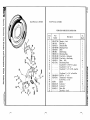
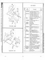
Frame for Vibratory Roll
Cover — Roll Shaft .
Cover — Frame End
Top Bar — Scraper
Bottom Bar — Scraper
Rubber Scraper
Decal — Frequency
Pin — For Safety Link — Steering Lock
Safety Link — Steering Lock
Hair Pin — Steering Lock
Cut Washer 1'4"
-L--Cotter Pin '4" x 2'4"
502-5995-80
Wheel — For 23.1/18-26 Traction Tire
298-6023-68
Inndr Tube 23.1/18-26 with TR150CW.
Hand Bendable Rubber Valve •
298-6014-68
Tire — 8 Ply 23.1/18-26 All Weather
— A.W. Thread — Code R-3
298-5534-68
Plug — Valve Hole (PG #1 or 421)
.502-2247-80 . Post — Seat Support Mounting
502-4485-80
Support — Operator's Seat
502-2822-80
Plate — Seat Mounting
102-8077-1
Orbitrol Steering Unit — (See
Separate Illustration)
Cadmium Plated Carriage Bolt
1/. .. ,t3 4 te
•-• -•—•
8
.
502-7087-80
102-4518-1
102-3655-1
102-3818-1
102-3819-1
102-3820-1
102-8368-1
502-2881-80
502-2870-80
298-131-47
.• 21
22
23
i 24
25
' 26
27
28
29
30
31
32
N C-4r4 C•4C`I.-•
2
1
'.3
14
5
6
7
298-12015-17 Lamp Assembly. (GMC #910900)
298-12014-1f Lamp Assembly (GMC #923-40)
298 12043 17 Seal Beam Replacement Unit •
•
(GM #5953035)
Switch — Two Position
298-6019-17
Wire Assembly & Fuse
502-173-80
298-5526-68
Grommet — V," I.D. •
298-53-17
Wire Nut #74B
Wire — (#12 Gauge - Automotive
x 2' -6" Long)
Wire (#12 Gauge - Automotive
•
x l'Lg.)
Electric Loom '/" I.D. x 2' -2" Lg.
•
Electric Loom '/" I.D. x 10" Lg. .
Wire Set•
102-3821-1
298-26010-17 Terminal Wire
Instrument Cluster (Includes • •
102-4375-1
Items 14 Thru 17 Assembled)
Gauge — Amps (Stewart Warner
440436)
Gauge — Temperature (Stewart
Warner 442784)
Gauge — Oil (Stewart Warner 444642)
Gauge — Fuel (Stewart Warner 441343)
502-4406-80
Cover — Instrument Panel
298-278-47
Knob — Steering Wheel.
602-5925-1 • Vibratory Roll Assembly — Reference
Only — (See Separate Illustration for
Details)
4
"
.
1
No.
Reqd.
'
Description
Al wa ys Gi veSerial Numberof Machine
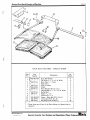
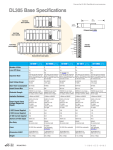
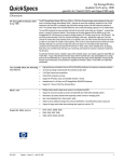
INSTRUMENT CLUSTER — LIGHTING DIAGRAM
. ROLL — FRAME & SCRAPERS — DRIVE WHEELS & TIRES — •
REX SELF PROPELLED VIBRATORY ROLLER
•
•
'
.b.
00
448R-8
•
Always Give Serial Number of Machine
■•• •■•■••••••
Oka.
•
. .
e:.
41
•
1
•
I I
I
I
I I
• I
I I
I
•
•
•
•
•
•
•
tr•M• ••••••■• ••■•■ •• Mb SWIM, •••••• QM. ••••• ••■ •••
till
•I
• •i •
i •I
>..•.•s
• s
,,
■
a. ,....:.
r--,
•• •
: •.'
1•
1... ♦
.
•
e.
I.
«
\454.• ,
L.
..___
...v..-- .....
•I
5
.•.
I
I •
all,
e....
•
CD...,
as •
CD
•
.1
.......
cop.
gerqie
,
I
Ii
.--•••••••■••• .*—
I
: US
toI
CDI
.,
y
I
•
.•a
I
I
t ea
4 ..
CD
•
4,0M WIMP
1•••
•
MO M••• •••• ■•••
0.
I
..
90
:
#,
I•
•
••• •
.0. •
• # •
1.
.
•••
- ••
CD
•
.
•
•
- - •
..•°
-•
--••••••
1.• •
ti
Specify Quantity, Part Number
and
Description When Ordering
• ,
•
1 .
SpecifyQuantity, Part Numberand Description When Ordering
Item
No.
Part •
Number
Description
1
2
3
4
5
6
7
8
9
10
502-4456-80
102-3668-1
102-3669-1
298-241-2
298-8014-11
298-5075-92
298-123-2
..
Bracket — Two-Speed Support
Bracket — Two-Speed Shift
Lever — Two-Speed Shift
Bearing — Flanged Nylon
Shoulder Bolt
Rod End — Male (Spherco No. FRE-6)
Rod End — Female (Spherco No. TR6)
Cap Screw '4" x w/Nut, L.W.&C.W.
Lock Nut '4" U.N.F.
Instrument Cluster (Amps. —.Temp —
Tach. — Oil — Fuel) — (See Separate
Illustration for Details)
Flexible Shaft — Tachometer
Cable — Pull to Stop (Series 20)
Clamp (Kickhaefer HCOV-0413)
Cable — Emergency Stop
Lock Switch — Ignition (Cole Hersee
Co. #95522A)
Push Button Starter Switch (Cole
Hersee Co. #9216)
Clamp — Conduit (Not Illustrated)
Mounting Bracket (Emergency Stop
Cable)
Control Assembly — Throttle & Travel
(Morse Controls Inc. #E44920 —
Consisting of Items 19 thru 39 Incl.)
Cable Fitting
Pin — Lever
Knob — Red
Shaft
Knob — Handle
Trunnion — Shift (40 Series)
Gate Plate
Lever Assembly (Forward - Reverse)
Support — Cable
Lever Assembly (Throttle)
Adaptor Plate
11
12
13
• 14
15
298-2011-71
102-4375-1
102-3302-4
102-7957-1
298-9032-86
102-7957-2
298-6068-17
298-6067-17
16
. . :17
18
19
20
21.
22
23
24
25
• 26
27
28
29
102-7958-1
102-8022-1
102-8099-1
*A31980
*A32023
*A41485-2
*A43698 *B43671
*1344720
*1348509
*1348871
*1348894•
*D43274
*D43683
No.
Req'd.
Item
No.
;30
1
1
1
1
1
1
1,
2
1
Part
Number
*E43696
; 31
32
33
' 34
1
135
1.36
1
1
1
1.
1
52NTE054
E37
38
1
'39
40
2
41
42'
102-7963-1
1
43
102-7244-15
44
45
102-3733-1
102-8090-1
46
47
502-2792-86
.48
102-8104-1
49
50
502-4460-80
•
1
2.
1;
•
1
1
1
1.
1
'
102-8100-1
Description
Housing
Screw — Hex Head 14" - 28 x '/," Lg.
Washer — Split Lock '/"
Screw — Hex Head '4" - 24 x '4"
Washer — Internal Tooth '4"
Screw — Filister Head Machine
#10-24 x '4" Lg.
Nut — Hex '4," - 18
Screw — Phillips Fil. Hd. 64," - 18
x l'4" Lg.
Elastic Stop Nut (For Item ta4 —
Not Illustrated)
Screw — Phillips Truss Hd. x10-24 x. •
sw Lg.
Screw — Phillips Truss Hd. — SelfTapping #10 x '4" Lg.
Cotter Pin '43 " x '4" Lg.
Mounting Flange (Morse #46595) .
(Not Included in Item #18)
Flat Head Machine Screw 1/4" x 14"
Control (Two Speed Shift) (Morse
#D48996)
Control Cable (Morse Series 60
#63B66)
Bracket — Valve Cable — Exciter
Hydraulic Unloading Valve — Exciter
Control (Eaton Electro Hydraulic
Div. #R1264-011)
Control Lever — Exciter Valve
Cone Point Set Screw '4" x '4"
(Nyloc) — (Lever Stop Adjustment)
Cable (Morse Series 30 #D38033)
(Exciter Control)
Support — Brake Cylinder
Cap Screw '1," x 1" w/Nut & L.W.
Na.
Req'd.
1
2
2
2
2
1
1
1
1
4
1
1
1
6:
1
1
1
.
1
1.
2
1
1
4
auttpen lo zacitunN Ryas aAlD sAealry
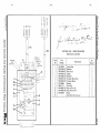
INSTRU MENT PAN EL AND CONTROLS
EXCITER — FORWA RD OR REVERSE — BRAKE
TWO SPEED TR ACTION TRACTION WHEEL & TIRE
INSTRUMENT PANEL AND CONTROLS•
•
EXCITER — FORWARD OR REVERSE — BRAKE
TWO SPEED TRACTION — TRACTION WBEEL & TIRE (Cont'd.)
Item
• No.
1
.
102-8109-1
........
102-8109-12
298-5019-92
298-5020-92
298-2129-62
•
2985017-92
' 298-5018-92
502-2306-83
51
502-2306-84
'
298-5580-68.
•:
i
Part
.•• Number
,
298-5581,68
.
- 298 2012 71
-
-
••
Description
-
Masai Biale Cylinder (Wagner
iFE3086)_.. _
r
Repair Kit for Master Brake Cylinde
(Wagner iF11301)
Connector Bolt (Not Illustrated)
Brake Cylinder Connection (Not Illust.)
Frame Tee & Distributor Connector —
Brake Lines (Not Illustrated) .
Copper Gasket (Not Illustrated)
Copper Gasket (Not Illustrated)
Brake Line — Copper 72" Lg.
(Not Illustrated) •
Brake Line — Copper 96" Lg.
•
(Not Illustrated) Brake Hose %" I.D. x 5'4" Lg. •
(Not Illustrated)
Brake Hose '4" I.D. x 19"4," Lg.
(Not Illustrated)
Cap Screw %" x 3%" U.N.C. •
Lock Nut %" U.N.C. ' ..
No.
Req'd.
'Item
No.
.
1 .
'
1
• 1•
1
53
•54
55
; 56
157
58
59
60
61
62
63
1
1
1
1
1
1
1
2•
2j
Part
Number
•
i
1 64
1
65
. .66
67
68
102-1991-1
502-2791-80
.
•
-.---298-80-47
402-1596-2
102-1891-1
102-7245-8
102-7554-2
203027-2
298-263-47
X203049
102-7945-1 .
..
Description
. .
No.
. Req'd...
..
.••-•
Yoke End
Lever — Brake Pedal .•
Cut Washer 1" .
Cotter Pin',(" x 2"
Clevis Pin
Cotter Pin %," x '4"
Pad — Brake Pedal
Spring — Brake Lever /
Set Screw '4. x 2"
Hex Nut '4,"
Control Cable — Throttle (Morse
Series 30 033BC180)
Control Cable — Direction (Morse
Series 40 #431118
0)•
Wire — Amp to Ignition Switch
Ball Joint s10-32 and '4-28
Ball Joint '4,"-24
'.
eover — Master Cylinder . .
,
1 •
1
•1
1
1
1
1
1 •
1
1 •
1
1
1
2 '
1 .
1 .
.
448R-11
Always Give Serial Number of Machine
Timm ow I
•••■•-•••... •■ ••••••-•• •
*
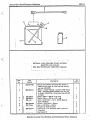
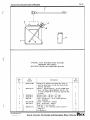
AIR CLEANER
CYCLOPAC F.W. SERIES
REX PART NO. 102-8103-1
DONALDSON CO., INC. #FWA10-0017
I. •
Item
No.
1
.2
...:3
' '4 "
'5
6
.7
'8
.9
t
PartNumber
-
Description
Body Assembly (Reference Only) Yoke (Reference Only)
Element Assembly (*P10-1234)
Gasket Washer
Thumb Screw (Reference Only) Clamp Assembly (Reference Only)
Baffle Assembly (Reference Only)
Cup Assembly (Reference Only)
•
•102-8103:4 . Cup Gasket (*P18663) .
.
102-8103-2
102-8103-3
la
Req'd.
-
..
1
1
1
1
1
1.
1
1•
1
•. •
Specify Quantity, Part Number and Description When Ordering
- Always Give Serial Nu Inbar of Machine
• 448R-12
..
•.
••
•
• • V,
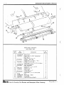
• ARTICULATING JOINT — STEERING CYLINDER
•
ROLLER FRAME — SCRAPER
•NOTE Due to availability machine may be' equipped with
Lantex Hydraulics series BL steering cylinder-see
•
seperate illustration.
ItemPart
No.Number
3
4
5
6
7
8
9
1
298-2010-71
502-4396-80
11
12
{298-2016-71
1502-7087-80
1502-7087-81
102-4517-1
102-3725-1
13
14
15
16
17
18
19
20
21
22
23
24
•25
26
102-3725-2
102-3725-3
. 102-3725-4
102-3725-5
102-3725-6
102-3725-7
102-3725-8
102-3725-9
*102-3725-10
102-3725-11
102-3725-12
102-3725-13
102-3725-14
102-7505-1
10
'
{
502-4395-80
102-7923-1
102-7924-1
102-7924-2
298-6805-8
102-7919-1
#1610
.
Description
Cross Shaft
Bearing Spacer
Shim %," (As Needed)
Shim %," (As Needed)
Self-Aligning Bushing (R.B.C. #B32-L)
Bearing Cover
Lubrication Fitting ' 114"
Cap Screw Y," x Ph" w/L.W.
Lock Nut %"
Cap Screw %" x 21/2" w/L.W.
Bracket — Bearing Housing
H.C.-H.T. Cap Screw 3Au x 5" .
Lock Nut 3/4"
Frame for Roll (Reference only)
Straight Frame for Roll (Ref. only)
Scraper for Frame Roll
Hydraulic Cylinder — Steering (Consists
of Items 13 thru 25) •
Nut (Cross Mfg. #1A0146)
Head .Cap (Cross Mfg. #1C1528)
Head (Cross Mfg. #1C1648)
Piston (Cross Mfg. #1C0005)
Rod (Cross Mfg. #1C9679)
Tube Assembly (Cross Mfg. #1C9678)
Retaining Ring (Cross Mfg. #1A0004)
Cap Screw (Cross Mfg. #1A0300)
Seal, T-Ring (Cross Mfg. #1A0315)
"0" Ring (Cross Mfg. ll1A0003)
Seal, T-Ring (Cross Mfg. il1A0314)
Seal, Wiper (Cross Mfg. n1A0019)
"0" Ring (Cross Mfg. #1A0051)
Ball Stud 1 le- 12 U.N.F. Internal
Thread (Vickers #922945)
*For Service Part No. 102-372-12 will be replaced by
107-17?C-Ic "(1'' Pitir (Cro.;!: 1 A00201
No. • .
Req'd.
1
4
8
4
4
4
4
16
12 :
12 '
1.
811
.
1.
1
2!
1
1
1
1
1
1
1
3
,
'
•
;
1
1
1 !
2
Al ways GiveSerial Number
•
I
Always Give Serial hrunib3r of Machine
448R-14
••
s.
...II.
' a
•
at
I
O
4'
CID
ger
••••
a)
—
4
I CD
it 0•s1
IV,
lig
0% • a•
0-i
•I
•
tl
i•
•00
•
•
8
•
•
•9
••
••
ft ••
••
•
•
.
•
es...,
•••••
t
SpecifyQuanti ty, PartNumberand Description Wh en Ordering
.
.
Item Part
Number
No.
Description
,
-a.
•
.
502 -5979-80*Roll
Inspection Cover
{102-3647- 1
Self-Locking Cap Screw %" x 1 "
• I 502-4384 -80 Wheel
298-6035-68 Tire — Model G800 - 165/380 Ply
3
293- 6036- 68 Tube — 5:00 x 15 — Heavy Duty.
Self-Locking Cap Screw %" x TA"
298-46-93
4
Lock Washer %"
.
5
Shaft
6 * 102 -5194 - 1
Weight — Eccentric Shaft
7 * 102 -3652- 1
Square Hd. Cup Point Set Screw % "x23,4 "
•8 * • 9 * 293-2035 -71
Lok Nut '4"
Hub — Drive Side
402-2606-2
10
Hub — Driven Side : • ,
402-2607-2
11
14" x2 "
'Set
Socket Hd., Dog PointScrew
: 12
Hub — Wheel
13
402 -2605-2
Self-Locking Cap Screw 34 " x 3 " with
298-32-93
14
i
'A" L.W.-.
Spherical Roller Bearing (SKF452320)
15
298-273-2
Bearing Cup (Timken 014435010)
{298-274 -2
• 16
Bearing Cone (Timken #L435049)
298-275-2
Oil Seal #415379 (For It. 6 - Shaft 3 3,4 ")
298-3089-68
: 17 •
Oil Seal 7 '14," I.D.
298-3093 - 68
18
Oil Seal 81/2 " I.D. (#415489)
298- 3094 - 68
19
502 -4383-80 Tire Housing — Half
• 20
'4 " 21/2 " w/Hex Nut
Cap Screwx
21 1 102-6927-1
S"
L.W.w
...
1
Item
1,1o..
No. .
Req 'd.
1.
2.
4
2
2.
2'
12
12
1
2
2
2
1
•1
6
2
16.
2
4.
4
2
2I
21
4i
8 •
4 ;.
.
22
. 23
24
25
i 26
I 27
, 28
29
i 30
31
32
33
34
35
' 36
I 37
38
39
. 40
.41
42
.
Part
Number.
• .--..•
No.
Description
••••••. ... •. Req 'd.
Ring — Carrier Bearing
Shim (.005 " )
Shim (.0075 ")
Shim (.020 " )
Tab — Bolt Lock
H.C. -H.T. Cep Screw %" x 1% " .
102-3646- 1
Ring Spacer — Bearing . •
402- 1693-2.. Retainer — Labyrinth Bearing .
Self-Locking Cap Screw 1/2 " x 1 1/2 "
{298- 12-93
Lock Washer 1/2 ".
Flange — Wheel & Motor Mount
402-2604-2
Self-Locking Mach. Screw '4" x 1" •
298- 19-93
Woodruff Key #1210
Cut washer 7/8"
.
2 -645-71 Lok Nut % - 14 "
.129-3:
•
102-7901 - 1
Cover
Socket Head Cap Screw 34" x 1"
1298-4 -93
• Lock Washer 1/2 "
X7846
Grease Hose
X7328
Grommet
Lubrication Fitting #16138
Pipe Coupling %" .
{
Cut Washer '/,"
. •
102-7974- 1
Coupling — Drive Half
102 -7975-1
Coupling — Driven Half •
102 -7976- 1
Coupling Sleeve .
298-3095-68
Hub Seal
298-7020-34
Snap Ring
.
102.45164
1 102-7897- 1
102-7897-2
102 -7897-3
102 -7900- 1
For replacement order 502 -2932-80 Shaft with Weights
(design improvement — Identical except pre -welded).
II .
•
2
6
6
6
12
12
2
2
12
12
2
8
1
1
1
1
.
.
;
•
•
4
4
2
2
2
2
4 .
•1
1
1
2.
2 .
Al wa ys GiveSerial Numberof Machine
VIBRATORY ROLL ASSEMBLY
ASSEMBLY PART NO. 602 -5925- 1
Always Give Serial Number of Machine
448R-16
•41
40
I-iYD RAU
C 'TANK
33
32
I!
11
15
3- 39 .
38•- .12
10
11
34
35
36
37
14
Wk1 =•'•0
MI:
17
■
34
0 11 t.i 11.
15
t
'
.'1
1237;:R-A
ot MOP
II
•
CO ROL C A BLE
1/
-4 2
Jai&
43
45
"V I
40
39
38
30
29
it
11
10
41
4•11,
24
23
16
1
20
WI. EMI.
19
pp
is
P•41•• AMY IV
41
VIEW
A- A
•
12
13
14
19
22 23
25
die
rasS•111•1
•••11111P
•••••• •=1.1• ■••■■•••••
. - •
Specify Quantity. Part Number
21
••
and Description When Ordering
Always Give Serial Number of Machine
448R-17
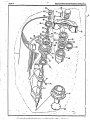
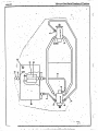
VIBRATOR
HYDRAULIC SYSTEM
REX SELF-PROPELLED VIBRATING ROLLER
.....•■••■■••••■•
Part • Number
Item
No.
1
2298-8115-86
3298-8116-86
4298-8117-86
5298-8076-86
298-2231-62
6
102-8090-1
7
102-8088-1
8
102-3703-1
9
102-3704-1
10
102-3705-1
11
102-3695-1
12
102-3702-1
13102-3706-1
14
298-9005-86
15
102-3718-1
16
102-3730-1
17
102-3731-1
18
298-2141-62
19
20
298-6524-86
21
22
23
24
25
26
27
102-8089-1
28
102-7883-1
29
30
102-7884-1
31
102-3690-1
32
298-4-95
33
102-8094-1
34
298-9035-86
35
36
37
102-1594-4
38
39
298-8033-86
40
41
42
298-3500-68
43
298-2234-62
44
45
46
298-142-53
. -
No.
Req'd.
Description
Pipe Coupling (1" N.P.T.)
"0" Ring Reducer l'A" x 1"
"0" Ring Branch Tee I" x 1" x 1"
Swivel Nut Branch Tee 1" x 1" x 1"
Elbow 90° — 1" "0" Ring x J.I.C.
Hose Stem — 11/4" - 90° Split Flange
Dump & Relief Valve (see separate Ill.)
Hose 11/4" x 10"
Hose Assembly
Hose Assembly
Hose Assembly
Hose Assembly
Hose Assembly
Hose Assembly
Hose Clamp
Oil Cooler
Hose Assembly
Hose Assembly
Straight Adapter 1" J.I.C. — N.P.T.
Pipe Tee — Galvanized I" N.P.T. •
Elbow 90° — 1" J.I.C. •— N.P.T.
Reducer Bushing 1" x 3/4" N.P.T.
Close Pipe Nipple 3/4" N.P.T.
Elbow — Galvanized 3/4" N.P.T. x 90°
Close Pipe Nipple 1" N.P.T.
Elbow — Galvanized 1" N.•.T. x 90°
Check Valve — 45 P.S.I.
Nipple 3/4" N.P.T. x 2'4" lg.
Pump — Hydraulic (See Separate Illustration)
Motor — Hydraulic (See Separate Illustration)
Adaptor Plate In-Frame
Spring
Bar — Connecting
Hose Clamp
Cap Screw '4" x 1" 1g.
Lock Washer %a
509Hex Nut 14.
"0" Ring — S.A.E. 1"
Split Flange Clamp 1"
Cap Screw H.C.-H.T. 34" x 11/4"
Lock Washer '4"
"0" Ring = S.A.E. 11/4"
Split Flange Clamp 11/4"
Cap Screw H.C.-H.T.x 1'4" lg.
Lock Washer %N .
Filter-sump type-100 Micron
(Marvel 150-11/2-100)
•1• • • • or •
1
2
1
1
3
1
1
1
1
1
1
1
1
1
1
1
1
1
2
2
1
2
2
1
2
1
1
1
1
1
1
1
1
4
1
1
1
5
10
20 :
20
1
2
4
4
1
imiciimunimemmunineme menows■mi
Specify Quantity, Part Number and Description When Ordering
▪
•
448R-18 -
-•••'-
•NS'
...s
1G-•••••••••••••• -war-Mow
----Always Give Serial Nurabei of Machine
• •
12 •
a/.
•
. .
•
•
.1.••• ••
16
4
aro's
•
•
'OOP
•
am.
•
•
.• •
7..
.• Z.•••
18
IMP
•
14
17
war
41•••e
.•
• . .0 1,6.2.,;•••
•
•
••
• :. .
sz.
..•• ;; ••
-
jr
13
Always Give Serial Number of Machine
448R-19
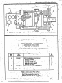
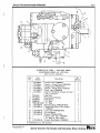
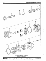
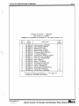
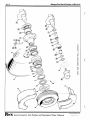
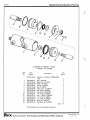
HYDRAULIC MOTOR — EXCITER DRIVE
REX PART NO. 102-7884-1
COMMERCIAL SHEARING & STAMPING CO. NO. M25X-978-BEVL-15-7
Item
No.
Part
Number
1
102-7884-10
102-7883-22
102-7883-23
102-7883-11
102-7884-14
102-7884-15
102-7883-28
102-7883-29
102-7883-30
102-7884-19
102-7883-33
102-7883-34
102-7883-35
102-7883-15
102-7883-17
102-7884-24
102-7883-16
102-7883-10
2
3
4
5
6
7
8
9
10
11
12
13
.14
15
16
17
18
Description
Check Assembly (*M1391K)
Shaft Bushing (*A112010)••
Spring (*A1327-182)
Roller Bearing (*S1032)
Retainer Ring (*LA1072) Hi-Pressure Seal (*X73-50-3)
"0" Ring (*63006-26)
Tapered Roller Bearing (*X126-8)
Shaft End Cover (*XA1686-3)
Drive Gear (*KA1007M-15)
Shaft (*PI31135)
Spacer (*YA-1669-1)
Retaining Ring (*X97-100)
Thrust Plates (*Y1058)
Gasket (*UB3006-244)
Gear Housing (*MA1688-15-64)
Pocket Seal (*K3026-27)
Port End Cover (*RA1603)
No
Req'd.
2
1
1
4
1
1
1
1
1
2
1
1
1
4
2
1
12
1
*Commercial Shearing & Stamping Co. - 1775 Logan A ye. Youngstown, Ohio 44501 part numbers.
Specify Quantity, Part Number and Description When Ordering
44S1Z-20
Always Give Serial Number of Machine
..
.. 16
an,
MO.
/
•
.
...
•• '
/----
/
/
ow'
.
-
---
•••••"". ..*
Ng. • -''' 4
.
•
.••••••
•••••'".
.••••""
.••••••"'
•
••••
po"'" •
00-
ow'
Aro.
aro"
4.001
••••°'
.001
• •••••■•••
•
15
••
•
CO
••• ••
Specify Quantity. Part.Number and Description When Ordering
...a' •
••••••
•••*"..
Always Give Serial Number of Machine
=N.M.
• 418R-21
•••• ■••■•■■•■•••■••••■••••■• ••• • ••■••••• •■••■ •■•■•■•■•••••■ •■•••
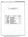
HYDRAULIC PUMP — EXCITER DRIVE
REX PART NO. 102-7883-1
COMMERCIAL SHEARING gP25X-178-BERS-12-7
Part
Number
Item
No.
1
2
3
4
5
6
7
8
.9
10
• 11
12
13
14
. 15
16
-17
•18
.
102-7883-10
102-7883-11
102-7883-14
102-7883-15
102-7883-16
102-7883-17
102-7883-22
102-7883-23
102-7883-25
102-7883-26
102-7883-27
101.7383-28
102-7883-29
102-7883-30
102-7883-31
102-7883-33
102-7883-34
102-7883-35
No.
Req'd.
Description
1
4
1
4
12
2
1
1
1
1
1
1
1
1
2
1
1
1
Port End Cover (*RA1603)
Roller Bearings (4 S1032)
Gear Housing (*MA1688-12-34)
Thrust Plates (*Y1058)
Pocket Seal (*K3026-27)
Gasket (*UB3006-244)
Shaft Bushing (*AH2010)
Spring (*A1327-182)
Retainer Ring (911072)
Double Up Seal (*X73-37-13)
Seal Retainer (*SA1669).
"0" Ring (*63006-26)
Tapered Roller Bearing (*X126-8)
Shaft End Cover (*XA1686-3) •
Drive Gear (*KA1007M-12)•
Shaft (*PB1135)
Spacer (*YA-1669-1)
Retaining Ring (*X97-100)
*Commercial Shearing & Stamping Co. - 1775 Login Ave. Youngstown, Ohio 44501 part numbers.
•
.1s
•
,
11:111"1111M111111:121212=1:r7""1
nnpr•ify llnantifv. Part Thlmhnr anri TI,nprintinn Whezn OrriPrinn
• Always Give Serial Number of Machine
448R-22 •
do •
11 14
1 0 1G 7
- 13 • 2
20
17 1256
•
...114■4•13,•••••••
-t .`7
27
28
frirVIX
■1
;AX26
N. 'It_ Wpir I
4
21...-- •23
•24
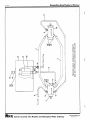
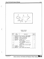
• HYDRAULIC UNLOADING VALVE — EXCITER CONTROL
FAWICK CORP. HYDRAULIC — ELECTRONIC DIVISION NO. R1264-011
d-REX PART NUMBER 102-8090-1
Part
Numbir
Item
No.
1
2
3
4
5
6
•
.7
8
9
10
11
12
13
14
15
16
17
18
19
20
21
22
23
24
25
26
27
28
*200-245.
*265-003-013
*285-100
*230-043
*268-031
*220-044
*310-057
*267-507
*310-095
*250-001-015
*230-015
*285-055
*265-006-075
*250-001-123
*250-001-130
*285-020-050
*250-014-123 •
*265-503-003
*265-501-002
•310404
*310-139
*310.140
*267-517-001
*285-224
*250-001-00S
*230-044
*310-056_,
•
MED
No.
Req'd: .
Description
Valve Body
Ring — Retaining
Sleeve — Valve
Spring
Pin — Metering
Piston — Valve
RetainerSpring
Screw — Adjusting
TubeStop
Seal — "0" Ring
Spring
Valve — Poppet
Ring — Snap
Seal — "0" Ring
Seal — "0" Ring
:
• . .
Ball
Ring — Back-Up
Not Used
Nut — Acorn
Nut—Jam
Knob
Handle
Detent
Screw — Set
Valve — Dump
Seal — "0" Ring
Spring
Ratchet •
I-
*Fawick Corp. — Hydraulic-Electronic Division —
‘ Cleveland, Ohio part numbers.
.0...••■•■•
•
Specify Quantity, Part Number and Description When Ordering
0•■•••■•■,■■■•■
I
1
1
1
1
1
1
1
1
1
1
I
1
1
1
1
1
1
1
1
1
1
1
1
1
•
.
.
Always Give Serial Number of Machine 448R-23
•••■•••• '••• •
STEERING CYLINDER
LANTEX HYDRAULICS INC. NO. 571-01 SERIES BL
REX PART NO. 102-3866-1 ..
'USED AS AVAILABLE AS AN INTERCHANGEABLE ALTERNATE
FOR 102-3725-1 CROSS HYDRAULIC STEERING CYLINDER. CAUTION CHECK CAREFULLY AS THE FOLLOWING PARTS
. CAN BE USED ONLY ON THIS LANTEX CYLINDER
Item
No.
1
2
'3
4
•• 5
6
.7
.
Part —
Number
102-3866-2
102-3866-3
102-3866-4
102-3866-5
102-3866-6
102-3866-7
. 102-3866-8
4
.*
Description
-•---- Locknut (Lantex 50064) Piston (Lantex 203-06)
Rod (Lantex 570-03)
Barrel Assy. (Lantex 567-02
Gland (Lantex 109-05)
Gland Collar (Lantex 249-11
Seal Replacement kit
(Lantex 50455)
.. _
No.
Req'd.
.
•1
1
1
.1
•• 1,
1_
..
• .....
1.
Specify Quantity, Part Number and Description When Ordering
.*.
.448R•24
Always Give Serial Number of Machine
POWER STEERING CONTROL UNIT
CHAR-LYNN CO. "ORBITROL" MODEL SCB-UM-11
REX PART NO. 102-8077-1
SpecifyQ uantity, PartNumberand Description WhenOrdcrin a
Item
No.
1
• 2
• 3
4
5
6
17
8
9
10
11
12
-13
14
15
161 •
17
18 •
.19
20 •
•
• Part
• Number
Description
Not Used
Not Used
Not Used
Not Used
•
102-8077-21
Snap Ring (*14092)
102-8077-22
Retaining Ring (*5245)
• 102-8077-23
Bearing Assembly (*21146)
•
Not Used
102-8077-24
. Steering Shaft Assembly (*5249-1)•
Not Used
•Not Used •.
. 102-8077-25
Tube and Flange Assembly (*5246-1)
Cap Screw Y."- 16 x 3/4"
102-8077-10.'
Drive (*839)
102,8077-11
Spacer (*20642) .
102-8077-12
Plate (*594)
102-8077-13
Gerotor Set (1.50 thick) (*612) .
102-8077-14
End Cap (*21176)
102-8077-15
Control Parts Assembly (*847.2)
102-8077-16 .
Seal Kit
*Char-Lynn Co mpany — 15151 Highway 5 — Eden Prairie, Minnesota
pact numbers,.
No.
Req'd.
2
1
1
1
. .
1
2
1:
1
1!
1
1
1
1•
'
•
4.1SR-26
=1:42:11=
• 1•
-AlmaysGive S3rial AT umber ollif achine
••• ■■■ •%-..• ••••••
•
•
••
- • -
- * •
• .•
••
•
• ••-.
•.
.41
•
alm."■••••3*.trtamnr:w.te
•
1.-422rose
l=2:=1:11nrematraupoetyr— ...4.a....omissrzaraftgrxz=wxr---'77
Item
No.
Part
Number
DescriptiOn
1
102-7949-10
102-7949-11
102-7949-12
102-7949-13
102-7949-14
102-7949-15
102-7949-16
102-7949-17
102-7949-18
102-7949-19
102-7949-20
102-7949-21
102-7949-22
102-7949-23
102-7949-24
102-7949-25
102-7949-26
102-7949-27
102-7949-28
102-7949-29
102-7949-30
102-7949-31
102-7949-32
102-7949-33
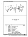
Manifold Sub-Assembly (*281409)
Cover Sub-Assembly (*286613)
Control Valve Sub-Assembly (*232797)
Ring (*296590)
Body Sub-Assembly (*296601)
Shaft (*250455)
Washer (*28931)
Screw (*199144)
Pin (*32559)
Screw (*171523)
Spring (*170072)
Plug (*175049)
Spring (*245507) • •
Pressure Plate (*276396)
Pin (*154364)
Vane Kit (*922594) (10 pcs.)
Rotor (*213859)
Cartridge Kit (*923092)
Bearing (*222440)
Snap Ring (*106641)
Bearing (*148423)
Key (*1606)
Snap Ring (*172376)
Seal Kit ( 1`922904)
3
.4
5
6
7
8
9
• 10
11
.12
.13
14
15
16
17
18
19
20
.21
• 22
23
24
*Vickers Incorporated — P.O. Box 302 —
Troy, Michigan 48084 part numbers.
No.
Req'd.'
1
1
1
1
1
;
1
3
1
4
1
1
1
1
2
1
1
1
1
1
1
1
1
'
cuppp.Atio zaqtunti Ryas eArD sAeitity
HYDRAULIC PUMP — STEERING
VICKERS PART NUMBER VTM42-60-75-15-MD-R1-12 .
REX PART NUMBER 102-7949-1
1.
•
448R-28
Always Give Serial Number of Machine
•
•••■•
•. • am. ••■•■•••1
ems. •■• • • o •
•
• •
•
•
•••■■■•• • • • =NM ••••• ••••••••
mow ow ••••••••••••■••••••••••••••,
**•
•0 •
•
•
0
0
•
•
111
001
Irmo •■••••
•
•
Vst
O
!VC°,
g•■ •••.
••■•
■•••••■
•Ml• MIND IM
AM.
•■•
01.
I
D
t#:
•
• •
• •
e•moa
•••••••••
•
mow ems .•••• ••• ■•••••••1111/
..
•
•
•
•
•
• •
011
•.
••••
4-'•
•
•••••re •_•••••••=,...,
..T....
...Tle•n•••••••••••
• • 0.4
•
•
...
••••• ••■••• •
1,•••••••••••■ ••••
•••
•
•
a
•
• I, •
0=seitza=e
t•
•
•
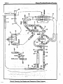
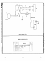
TRACTION DRIVE HYDRAULIC SCHEMATIC . •
. REX SELF-PROPELLED VIBRATORY ROLLER
•
Part
Number
Item
No.
102-3691-1
102-3683-1
502-2783-80
502-2785-80
298-8148-36
298-8078-86 •
1
2
3
4
5
6
7
8
9
102-8510-1
298-133-53
502-2733-80
102-7864-1
102-7320-1
298-8001-89
502-6035-80
102-1594-4
298-8033-86
.
;
11
12
13
14
15
16
17
18
19
20
...•
298-2070-56
No.
Req'd.
Description
Hose Assembly 1"
Hose Assembly 3/1"
Hose Assembly
Hose Assembly
. Elbow 45°
Straight Male Adaptor
Pipe coupling IA" .
Galvanized Pipe Coupling %",
Lock Washer V
Tube — Reservoir
Filter Element
Cover — Hydraulic Tank
Cover Gasket
Cap — Fill
Breather
Hydraulic Tank
"0" Ring
Split Flange Clamp 1"
Cap Screw %" x 1i4" .
Threaded View Gauge 1" N.P.T.
(Gitp BW20-4054)
2
1
1
1
i
•t
16
1;
;
1
;
4'
8
16
'
1
•
448R-3 0
=ammo
•
• •
• • ••...•• •
, .•••-
Always Give Serial Number of Machine
•.
••
•
•
••
•
-V
••
2". .1.•
.•
• ••••
r
/
•
I.'
is
•
.\ •
■•• .1••••• ••
.././Ato
■
•
z•re
1/V
•
A
swami
••••••• ow. ...
•.I••• •
• ■••••••
•••
• •• • • • ••• • ••. • •
•
• •••••• • •••
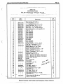
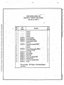
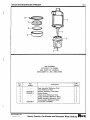
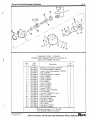
HYDROSTATIC MOTOR — TRACTION DRIVE
** SUNDSTRAND MODEL 22-3022
. REX PART NO. 102-6121-2 • ..
•
•
••• •■•• •••■•••••••••• • • • •• •••!. • • •• •••••••
• •••• ••••••••••
-•
• •
e•••••• ■•■•••••• AMMO •■ •••••■■•••••••:
•
••
••• •
•
•
•••••••••■•••■ 0
••••• ••• ••••
.
!"1°•
'
Part
Number
Item
.
102-4365-14
102-4365-1 -.
-•.
1
2
•
-
3
• .. .
..
102-4365-21
• •
••■•■
..
••••••
Manifold Assembly (*9800632-50)
Seal Kit (*9510022) Consisting of:`
*9210247 Shaft Seal.
*9210248 Housing Seal • ••
**9004102-1290 " 0" Ring
*9004100-2340 "0" Ring
*9220242 Seal Spring
Relief Valve Assembly (*9800370-50)
'**Refer to Identii:cation Plate on Pump
fog correct Model Number before ordering
parts — see separate illustration for •
• • Model 22-3055 (Rex Pad No. 102-S506-1). •
•
• • •
■•••••
•
•
•• •
•
,•••":.`,f; : .
mzsusco=2Lagx:Lir.s.ammterdass
•
.a
• •
.1
••
.
-
..
..
. No.
Req d.
•
Description
' 'Sundstrand Corp. part numbers.
• •..-
•- .. •- •••
• •
•
1 .
1
1
1 .
21..
6
1
••
.
•
S • ••••••■•
• •
i• s •
aat
Always Give Serial Number of Machine
• 448R-31
vtgammairraper
.221111117' FINOTS/a1=121/11Mr031:12L
2 .." •
HYDROSTATIC MOTOR – TRACTION DRIVE
**SUNDSTRAND MODEL 22-3055
REX PART NO. 102-8506-1
•
-_.—
Description
.
..Part
Number
Item
No.
102-4365-78
102-4365-1
1
2
•
•
.
•
•
102-4365-77
3
.
•
No.
Req'd..
-
Manifold Assembly (*9800834-53)
.
Seal Kit (*9510022) Consisting of: •
*9210247 Shaft Seal
•
.
*9210248 Housing Seal
.'1 9004102-1290 "0" Ring
• ' .
*9004100-2340 "0" Ring
*9220242 Seal Spring •
Relief Valve Assembly (*9800370-55)
1
1
.1
1
2
.
1
•
•
6
1
-
*Sundstrand Corp. part numbers.
.
.
•
•
**Refer to Identification Plate on Pump for correct
Model Number before ordering parts – see separate
illustration for Model 22-3022 (Rex Part No.
'
...
• • 102-6121-2).
Specify Quantity, Part number and Description When Ordering
.•
•
44SR-32
- Always Give Serial Humber of Machine
1127=1=7
. •
grume•ilv
Altym•rAr A nrI nizaxrrintirwt When _fIrriewiney
TWO-SPEED ' TRANSMISSIONFOR TRACTION DRIVE DIFFERENTIAL
SELF-PROPELLED VIBRATORY ROLLER
Part
Number
Item
No.
1
[
4
S
•
6
.7
8
.
9
10
11
12
13
14
15
16
47
.18
19
20
'21
22
23
24
Lockwire (•LW-168)
Lockwire (*LW-1620) — Transmission
to Axle (Location Shown — Not Illust.)
Nut (*N-16-1) — Transmission to Axle
102-6168-66
(Location Shown — Not Illust.)
Vut (*N-18-1) -= Hydraulic Motor to
102-6163-42
Adapter (Location Shown — Not Illust.
Plug (;P-18) Oil Filler & Drain
102-7872-14
(Not Illustrated)
•
Set Screw — Clutch Pinion (*S-865)
102-6168-53
Bolt — Transmission Case & Cover
102-6168-65
(*S-1611)
Nut (*N-16-1)
102-6168-66
102.6163-67 • Lock Washer (*WA-16)
Cap Screw (`S-2710) Idler Pinion Rear
102-6168-10
Cap & Front Cap
Cap Screw (*S-7710-S) Idler Pinion
102-7872-18
Rear Cap
Cap Screw (*S-2910-1) (Transmission
102-7872-17
Case to Carrier) (Not Illustrated)
Lock Washer (*WA-17)
102-6166-11
Lock Washer (*WA-18)
102-6168-41
Input Bearing Cup (*55443)
102-1514-20
Input Bearing Cone (*55187C)
102-6168-61
Bearing Cup (*3320)
X7857
Bearing Cone (*3377)
102-5163-22
Cup — Idler Shaft Pinion Bearing (Front)
102-6168-17
(*25821)
Cone — Idler Shaft Pinion Bearing
102-6168-18
(Front) (*25373)
293-45-2
Bearing Cup (*394-AS)
Bearing Cone (*395A)
298-115-2
Bearing Cone (*55187C)
102-6166-61
102-61€S-44
Stud — Hydraulic Motor Adapter
•
(*4-X-733)
102-6168-20
Key — Low Speed Gear (*16-X-103)
Lock Screw (*25-X-96)
102-7872-23
Oil Breather VA-11994-166).
102-61:3- 1 3
102-1514-15
Bearing ( 4 1226-Z-52)
102-5168-33
102-7872-11
3
{
Description
No.
Req'd.
1
25
26
27
28
29
:30
..31
32
'33
34
1
1
6
2
1
10
10 •
10
7*
1
8
7
4•
2
1
1
•
1
1
2
2
1
6i
1
1
1
1:
Part
Number
Item
No.
Description
Lock Ring (*1229-Z-1300)
Oil Seal (*A1S05-Y-545)
Bushing (*1825-M-117)
Nut (*1827-Y-285)
Nut (*1827-A-287)
Lock Washer (*1629-P-874)
Washer (*1829-U-879)
Dowel — Case & Cover (•1846•A-313)
Plug (*I350-Z-78)
Ball (*1898-11-34)
Shim (.010") (*2803-E-2085)
Shim (.005") (*2303-D-2034)
:35
•
Shim (.003") (*2803-C-2033)
Gasket (`280341-1100)
'36
'37
Gasket — Idler Pinion Cap
(*2608-W-1069)
102-6168-43
38
Gasket V260S-X-1090)
39
102-6168-31
Shift Fork (*2849-13-158)
40
102-7872-44
Shift (*2858-W-257)
41
102-7872-55
Cap (*3866-G-1021)
•
42
102-6168-47
Pinion (24T) (*3891-C-1199).
43
102-6163-19
Gear (55T) (*3392-N-2484)
• 44
102-7872-28 . Oil Seal (*A1805-X-648)
102-7872-39
.45
Shift Shaft (*2843-C-549)
46
102-3095-14
Cap— Idler Shaft (Front) (*3866-D-992)
47
102-7872-56
Case — Transmission
(*A4,A6-3875-U-645)
48 "102-7872-57
Cover — Transmission Case(*3876-G-475)
.49102-8095-17
Pinion (34T) ( 4'3891-N-1418)
50102-8095-18
Gear Lo-Speed Driven (45T)
(*A-3892-13-2524)
51* 102-7872-60
Pinion (2411— Clutch (*3891-R-1448)
52102-3095-25.. Collar — Shift (*3897-D-2526)
53102-8095-26
Adapter — Hydraulic Motor
(*A-3897-M-2405)
• ....
54102-1761-1 •
Gasket
'Rockwell Standard Corp. part numbers.
**Included in Item No. 47.
102-1514-14
102-616S-56
102-6168-54
102-6168-48
102-6163-35
102-6168-36
102-6168-37
102-6163-63
. 102-6163-34
102-6168-52
102-6163-16
102-6168-15
102-6168-14
298-2515-68
102-6168-24
1
No.
Req'd.
1
1
1
1
1
1
1
2
3
1
3
3
1
1
1
1
3
1
1
1
•
••
1
1
1
1
1
1
1 •
1'
1
;
13
•
op •• .••■•••••••■•••
a.. a •
24
' ""*".• •• •••••• • or.
••••...s
27
26
-.
r '.
1•
I
•• 36
•11
10 .33•
29 x'32
- .. . 25' ./0 " ..
•
.i. '
./ /‘ 6 •
/.
3 .'
, •
31 30) ,,' ..*#.'
...., .
. —
.
.
29
./
•
...27
....-' ■
...,
4•
/
37
ss 7
• -••
36.•
.••
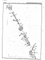
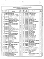
TRACTION DRIVE AXLE ASSEMBLY (INCLUDES TWO-SPEED TRANSMISSION)
REX PART NO. 102-8095-1
•ROCKWELL STANDARD CORP. NO. 35-3380
SELF-PROPELLED VIBRATORY ROLLER
Item
No.
Part
Number
1
2
3
4
102-6168-83
102-6168-42
102-7872-14
102-7572-16
5
102-1514-7
6
102-7572-14
7
8
9
10
102-6163-41
102-1514-20
102-5168-57
102-1514-5
11
12
102-1514-9
102-6168-61
102-7872-21
• 13
14
15
16
17
18
19
21
22
23
Description
1
102-7872-22
102-1514-15
102-1514-14
102-7872-26
102-7572-20
102-1514-16
102-7872-38
102-1514-22
102-1514-23
102-1514-24
102-1574-41
102-8095-29
102-6972-1
•
Lockwire ( *LW-1626)
Nut (*N-184)
Plug (*P-18) Filler & Drain
,Cap Screw (Differential Carrier Flange)
(*S-2311-1)
Rivet (*RV-7812) (Differential Case &
Bevel Gear)
Bolt (*S-1314-1) (Differential Carrier
Flange)
Lock* Washer ( *WA-18)
Bearing Cup ( *55443)
Bearing Cone ( *55176C)
Cone — Differential Case Bearing •
(*33281)
Bearing Cup (*33472)
Bearing Cone ( *55187C)
Bolt — Difftrential Case (Short)
(* 15-X-926)
Bolt — Differential Case (Long)..
(* 15-X-927)
Bearing (*1228-Z-52) •
Lock Ring (* 1229-Z-1300)
Pin — Bevel Gear Thrust Block
(*1246-G-293)
Plug (*1250-S-149) (Inspection)
Gasket (*2208-L-272)
Block Side Thrust ( *2297-A-573)
Shim — Bevel Pinion Bearing
(.003") (*2303-W-1791)
Shim (.005") (*2803-X-1792) ••
Shim (.010") (*2803-Y-1793)
Case — Plain Half ( *3235-P-354)
Carrier Differential ( *A3-3600-Y-649)
Differential Internal Assembly (Without
Case) ( *A2-3235-G-397) (Detroit Auto
Co. NS-21-63061) — Contains Items
26 thru 32 Inclusive
No.
Req'd.
Item
No.
Part
Number
1
10
2
24
102-8095-12
2
• 25 . 102-1514-18
12
10
10
2 •
1
26
27
28
.29,
2
2 i
1
30
31
32
102-8095-20
4
8
1
1
1 .:
1'
1
1 I
3 .
3 t
15:
;.33-
102-8095-21
34
102-6168-73
35
102-8095-28
•*36
37
102-8095-30
102-8095-48
.
Description
Case — Differential — Flange Half
complete with no spin differential
(Item 23), one of ( *35350) Drive Gear
and one (*35131) Drive Pinion
(Assembly Part No. *B-3235-X-882 —
6 44 to 1 ratio)
Matched Set Ring Gear (*35350) and
Pinion (* 35131) (Not sold separately)
Side Gear
Spring
Spring Retainer
Cam & Clutch Assembly
Holdout Ring
Spider
Snap Ring
Center Cam
Spacer Set for Differential Bearing Cup
(Not Illust.) Includes two each of •
* 1244-D-394 (.146") thru *1244-x-401
(.164")
Spacer Set for Differential Bearing Cup
(Not Illust.) Includes t•:o each of
* 1244-K-479 (.137") thru *1244-T488
(.179")
Spacer Set for Bevel Pinion Bearing
(Not Illust.) Consists of two each of
* 2203-N4054 (.219") thru *2203-Y-1065
(.254")
Cover — Differential Carrier
(*A48-3300-Z-468)
Axle Shaft (*3802-Y-1507)
Snap Ring (*1854-C-289)
*Rockwell Standard Corp. part numbers.
1
No.
Req'd.
1
•
ti
1
2.
2 '
2
2
2
1•
1
1
•
1 I
•
1
1
!
.
:
22
448R-36 •
Always Give Serial Number of Machine
Specify Quantity,_Eart Number and _Description
Vt1hr.n_ elyrinrhyv
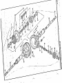
TRACTION DRIVE DIFFERENTIAL AXLE BRAKE END — WHEELS AND TIRES
SELF-PROPELLED VIBRATORY ROLLER
Item
• No.
1
2
3
4.
5
6
. 7
8
9
.10
11
12
13
14
15
16
17
' 18
19
20
• 21
22
No.
Description
Req'd.
..
•
2
102-6592-83
Plug (*P-212),.
16
102-7572-47t t Stud (Wheel Hub) (*20-X-262)
102-7572-46
Nut (Wheel Hub) (*1199-H-112)
16
Nut (Spindle to Housing) (*1827-R-252)
102-6592-36
24
102:8095-31
Plug — Planetary Spider Drain
(Not Illustrated) (*P-16) •
2'.
102-8095-32
Set Screw (Planetary Pinion Shaft)
.
(Not Illustrated) (*S-665)
6'
24
102-8095-33. Bolt — Spindle to Housing (*S-1920-1).
102-8095-34
"0" Ring — Hub to Spider (*5-X-589)
2
102-8095-35
"0" Ring (*5-X-590)
2
102-8095-36
"0" Ring — Spindle to Housing
(*5-X-591)
2
102-8095-37
Cap Screw — Planetary Spider to Hub
(Not Illustrated) (*10-X-667)
32
298-162-2 • Cup .:•- Hub Bearing — Inner (*27620)
2
102-8095-38
Cone — Hub Bearing — Inner (*27691) .
2.
298-65-2
Cup — Hub Bearing — Outer (*34478)
2
102-8095-39
Cone — Hub Bearing . — Outer (*34300)
.2
102-8095-40
Wheel Hub & Bearing Cup Assy. •
(Includes Items 12 & 14)(*A-322-J-452)
2'
102-8095-41
Nut — Hub Bearing Adjusting with
*18464-361 Pin (*A1227-H-736)
2'
102-8095-46
Pin only (*1846-W-361)
2:
102-8095-42
Oil Seal — Axle Shaft (*A-1205-W-829)
2i
102-8095-43
Oil Seal — Hub Bearing (*A-1805-Z-546) .2
102-8095-44 . 'Bushing — Wheel Spindle (*1825-Z-234)
2•
102-3095-45 . Washer — Planetary Pinion Thrust
(*1829-C-783)
6
102-8095-47
Snap Ring — Planetary Pinion
(*1854-Z-182)
6
Part
Number
I
Item
No.
Part
Number
Description
..
.
•• •
..
Button — Axle Shaft Thrust (*1898-Z-858)
Brake Drum (*3819-H-450)
Shaft — Planetary Pinion (*3880-H-814)
Pinion (13T) (*3891-W-1115)
Gear — Planetary Sun (20T)
(*3892-T-1814)
Gear — Final Drive Ring (46T)
(*3892-G-2997)
Spider — Planetary Pinion •
- 102-8095-55
(*A-3897-E-1695)
Spacer — Brake to Housing (Not
102-8095-56
Illustrated) ( 4 3897-R-2072)
Spindle — Wheel (*A3897-C-2447);
102-8095-57
Slinger — Oil (*3905-B-80)
102-8095-58
102-8095-60
Back Plate Assembly (*A-3736-Q-771)
Brake Shoe & Lining Assembly
102-8095-61
(*A3-3722-V-334)
Cam Bolt & Washer Assy.(*A-2747-A-105)
102-8095-62
102-8095-64 . ' Wheel Cylinder Assy.(*Al2-3261-P-16)
Cam (*2847-R-200)
102-6592-13
Spring (*2758-P-153)•
102-8095-66
Return Spring (*2258-T-124)
102-7572-57
"C" Washer (*1229-H-216)
{102-7572-58
"C" Washer (*1229-M-221)
102-7572-63
102-8095-67
Anchor Pin (*1759-L-38)
Nut (*N-114)
102-8095-63
Lock Washer (*WA-114)
102-1841-72
102-8095-49
23
102-8095-50
24
102-8095-51
25
102-8095-52
26
27 ' 102-8095-53
:.,.
.
102-8095-54
28
' . 29
1
30
31
;32
i33
•34
35
• .36
37
38
39
40
:41
*Rockwell Standard Corp. part numbers.
t
••••••• •
No.
'
Reqd.
2
2
6
6
2 •
2
•
2 ;
2 .
2 ;
2
2
.
2
2
2
4
4
2
4
4
4
4
4
•
e
00
AlwaysGire Serial Number of Machine
448R-38
•
•
..
it
4) •
- . _ - •-
7
.
Specify Quantity, Part Number and Description When Ordering
•
•
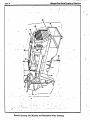
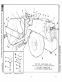
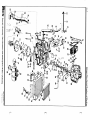
• MAIN FRAME — ENG INE HOUSIN G — OPERATOR'S CONSOLE
REX SELF-P ROPELLED VIBRATORY ROLLER
Item
No.
1
2
3
4
5
6
7
8
9
Part
Number
Description
Main Frame
Operator's Platform
Floorboard — Operator's Platform
Safety Walk Tape
Channel Rubber — Floorboard
Operator's Seat
Plate — Seat Mounting
Support — Operator's Seat
Mounting Post
Operator's Console
Cover — Instrument Panel
Cover — Brake Cylinder
Steering Wheel
Cap — Steering Wheel
Nut — Steering Wheel
Orbitrol Steering Unit
Hand Rail (R.H.)
Hand Rail (L.H.) • •
Fender (L.H.) (As Illustrated)
Fender (R.H.) (Opposite)
Safety Walk Tape
Fuel Tank
Cap — Filler
Support Angle
Spacer — Fuel Tank
Strap — Fuel Tank
Cotton Webbing 1/,," x 2" x.15' Lg.
298-2059-56' Sending Unit — Fuel Tank
298-9-97
Washer — Sending Unit
Gasket — Sending Unit
298-2511-68
Pipe Plug 1" (Tank Drain)
502-2786-80
Hose — Fuel Line — Return
502-2787-80
Hose — Fuel Line — Inlet
Pipe Elbow '4" x 90°
Reducing Bushing '4" x '4"
502-7088-80
502-6031-80
502-4454-80t
102-8085-3
X203699
298-214-47
502-2822-80
502-4485-80
502-2247-80
502-6025-80
502-4406-80
102-7945-1
298-68-47
298-69-47
298-9-71
102-8077-1
502-4412-81
502-4412-80
502-6032-80
502-6032-81
102-8085-2
502-5997-80
502-2799-80
102-7947-1
102-7948-1
502-2213-81
No.
Req'd.
1
1.
1
6
• 2•
1
1
1
1'
1
1I
1
11
1
1•!
1
1
1
1•
6
1.
1
1
1
4
1
1
5
1
1
1
1
1
2
Part
Number
Item
No.
10
Grille Shroud
Removable Grille
Shroud — Radiator & Pump Compartment
Cover — Front Compartment Shell
1502-6037-80
Shell — Front Engine & Tank
502-6035-80
Hydraulic Tank
Pipe Coupling 1st,"
102-8510-1
Tube — Hydraulic Tank
298-133-53
Filter Element
502-2733-80
Cover — Hydraulic Tank
102-7864-1
Gasket — Tank Cover
Cap — Hydraulic Tank
102-7320-1
298-2070-56
Sight Gauge — Hydraulic Tank
Breather — Hydraulic Tank
298-8001-89
298-13014-86 Sight Gauge — Hydraulic Tank
298-142-53
Filter (Gear Pump — Tank)
Reducing Bushing (1'4" x 1")
298-13010-86 Magnetized Drain Plug
1 102-4519-1
Engine Hood
[102-4520-1
Side Panel
298-5149-92
Muffler — Exhaust
1102-8103-1
Air Cleaner
1298-5127-92
Air Cleaner Cap
298-5010-92
Strainer — Fuel Tank
Cap Screw %" x 8" w/Nut & L.W.
(For Axle Mount)
{
11
12
.
'13
• I
:
114 •
•15
•16
17
18
502-6033-80
502-4457-80
502-5993-80
Description
.
No.
Req'd.
1
1
1
1
1
1
1
1
1
1
1
1
1
1
1
1
1
2
1
1
8
Always Give Serial Number of Machine
448R-40 •
•••••• •••••• .•
-
••••••••••• ••••••••••••• • MM. • • • • • •
•
.•.
14
.
g
OUT
10.
16•
re'
•••••
•
V.
POWER STEERING SYSTEM
REX SELF-PROPELLED VIBRATORY ROLLER
Item
No. •
1
2
3
4
S
6
7
•
8
•9
10
11
12
13
•14
15
16
.
.
&
.
Part Number
102-3701-1
102-3701-2 • 102 3701-3
202-3701-4
102-7033-S
298 8018-86
298-9018-86
298-2172-62
298-8112-86
298-2171-62
293-8110-86
- 298-8111-86
.102-8077-1
8 102-949-1
• 4502-6035-80
*102-37.25-1
• ••• ••=. •11••
■•••• •
•
•
Description
Hose Assembly W' x 75 1 1g.
Hose Assembly 2,4" x 88 %" lg.
Hose Assembly %" x 130" lg.
Hose Assembly W' x 102" lg.
Hose ',;" I.D. x 24" lg.
Hose Adaptor (%" MNPT)
Hose Clamp
Str. Adaptor (%" APT - % -16 STR)
Elbow 45$ (WI WIPT % -16 STR)
Elbow 90' (%" - % -16 STR)
Str. Adaptor (3 -16 "0" Ring •.
Elbow 90' (% -16 "0" Ring - J.I.C.)
Orbitrol Steering Unit
Pump — Steering
Hydraulic Tank
Hydraulic Cylinder — 3" Bore .x 20"
See separate illustration for details.
..,*
•
•
•••••=r • MIN.
..====asacesicgen=422macor=szasvage=a0=
.7 •
•
••••
L
Specify Quantity, Part Number and De3c.ription When Ordering
t
448R-41
Always Give Serial Number of Machine ...r•■•■•1,
VAD
OPTIONAL COLD WEATHER START BATTERY
MOUNTING AND CABLES
• REX SELF-PROPELLED VIBRATORY ROLLER
....
Item
No.
•
.2
•
I-
4
.
5
6
• 7
•
1
.
..
.........•• -.-•
Description
Battery Tray (Please note when this option is
used the main frame of roller has been altered
per dwg. 602-3072) .
Battery — Diesel Starting — 12 Volt AABM Group
298-3256-17
Size — SD (Delco Model SDR205, Part No. 761
• • or Exide, DS-8D7796 or Prestolite Type 8D-ASY
or equal
Battery. Cable — 000 Ga. x 73" long
102-83/S3-4
Battery Cable — #00 Ga. x 30" long
102-83S3-5
Acid — Electrolytic — 45 oz. Bottle (Military
298-3-44
• Spec. OS-801A)
Clamp — Hold Down — Battery
502-2693-80 •
Bolt — Hold Down — Battery
102-7766-1 •
Wing Nut '4" (Can be used)
Lock Nut '4" N.C. (Normally used in place of
298-2012-71
Wing Nut)
Cut Washer '4" .•
502-1579-S0
• 1
•
3
. •
Part
' Number
' No.
Req'd.
'
1
1
1
1
•
• 1
1
2
2
,
2
2
Specify Quantity. Part Number and Description When Ordering
•
Always Give Serial Number of Machine
448R-42 -
-
411111111110111,
•
•• •
••
• ••
•
•
•
.
INSTRUCTION —NAME PLATES —DECALS
NOT ILLUSTRATED .
•
•
•
•
- ----• •••• • • -No.
ItemPart
Description •
' Req'd.
e•
No.Number. ••.........• .• ..._. ..._•
._
.•
..•t_.
102-3248-1Plate— Lubrication-' •• 2
•"1
102-4546-1Plate —Instruction 102-1282-1 Plate — Model & serial no.
. • • 1
Type "U" Drive Screw 10 x 1/4"16 .
.1.3
402-1540-1 Name Plate — Rex
Nut & L. W. 5/16" •-9
1'
102-3736-1 Plate—Warning
1'
102-3737-1Plate—Lubrication —Maiht. 1
102-3788-1• Plate— Vibrator control .
1'
102-3789-1Plate — two speed control 1
298-4054-47 . Emblem —S M V -
• 2
102-3845-1 Plate — Warning 102-8368-1 .Decal — frequency (Ref. only see
.•
•.........
• instrument cluster illustration •1
•
.I"4N CO11.0t 00 CA 0
N
• .
•
-••
•
■
••
•
•
Specify Quantity, Part Number and Descrintion When
:•
••
manufacturers of:
truck-mounted concrete mixers
slip form concrete pavers
concrete spreaders
asphalt finishers
concrete mobile batch plants
concrete permanent botching plants
conveyors
computerized concrete and asphalt botching controls
soil stabilizers
single and double drum vibratory rollers
embankment compactors
sanitary landfill compactors
Rexworks Inc., Milwaukee, Wisconsin 53201 International Offices: Milwaukee, Miami, Bogota, Singapore, Paris
(414) 747-7200 Telex: 275371 Cable: REXCMDistributors in all principal cities of the world
Printed in U.S.A.
BULLETIN 463
S.P. VIBRATORY ROLLER
SERIAL NO. HX 151 & Up
9/72
REX CHAIN BELT
C
m
CONSTRUCTION MACHINERY SECTION, MILWAUKEE, WISCONSIN 53201
MANUFACTURERS OF:
Truck Mixers
Building Mixers
Pumps
Pumperete
Airport and Road Forms
I Pavers
aders
Finishers
Floats
Spray Cure Machines
Subgrade Planer and Tester
Slurly-Matic
Conveyors
Road Batch Plants
Central Mix Plants
Dry Batch Plants
Automation
Pulvi-Mixers
Trav-L-Plants
Pneumatic Compactors
Steel Wheel Rollers
Material Spreaders
Concrete Breakers
REX Pactor
S '.
r y ....`
INDEX
BULLETIN 463
REX SELF-PROPELLED VIBRATORY ROLLER
Eff. Ser. No. HX-157, Up
Description
AIR CLEANER ARTICULATING JOINT CONTROLS
Controls Assembly — Morse Controls Assembly — Operators' Console Control Box — Vibration Meter Controls — 2-Speed Shift Control Unit — Power Steering DAMAGE CLAIMS Page No.
4
41, 42, 43, 44
35, 36
31, 32, 33
30
34
39, 40
P1B
FRAME — ENGINE HOUSING, ROLL, TANKS 1, 2, 3
HYDRAULICS
Hydraulic Piping — Traction Drive Hydraulic Piping — Vibrator Hydraulic Pump — Steering Hydraulic Pump — Traction Hydraulic Pump — Vibrator Hydraulic Motor — Traction Hydraulic Motor — Vibrator Hydraulic System — Steering 9, 10
19, 20
38
8
29
14
21, 22
37
INSTRUCTIONS FOR ORDERING PARTS OPTIONAL EQUIPMENT
Optional Cold Weather Start Optional Water System Optional Wheels, Tires Optional Wheel Scrapers Optional Wiper Mats Roll and Tires POWER UNIT TRACTION DRIVE
Traction Drive Axle Traction Drive Hydrostatic Motor Traction Drive Hydrostatic Pump Traction Drive Transmission — 2-Speed Traction Drive Wheel Ends VIBRATOR
Vibratory Roll (R.H.) Vibratory Roll (L.H.) Vibration Amplitude Indicator P1B
56
45, 46, 47, 48
1, 2, 3
51
49, 50
5, 6, 7
11, 12, 13
14
8
15, 16
17, 18
23, 24
25, 26
27, 28
WATER PUMP — JABSCO 52
WIRING
Wire Sets — G.M. Wiring — Frequency Meter Wiring — Lights Wiring — Spray Bar 55
53
54
55
Always Give Serial Number of Machine p 1 13
INSTRUCTIONS FOR ORDERING PARTS
Order repair parts from your Rex distributor. Specify quantity. part number and name
of part. Do not order by reference number or state quantity wanted in terms of sets or
pairs.
Always give serial number of machine. This is very important. The serial number is
stamped on manufacturers' plate which is attached to the frame of machine.
Be particular to give complete shipping address mentioning town, county, and state.
Also give billing instructions and address. Tell whether to ship via parcel post,
express, air express, or freight.
DAMAGE CLAIMS
When broken goods are received, a full description of the damage should be made
by the carrier agent on the freight bill. If this description is insisted on, full damage
can always be collected from the transportation company.
We assume no responsibility for delay or damage to merchandise while in transit.
Our responsibility ceases upon delivery of shipment to the transportation company.
from whom a receipt is received showing that shipment was in good condition and
properly packed when delivered to them; therefore, claims for parts lost or broken in
transit should be made BY YOU to the transportation company.
REX CHAINBELT INC.
PRINTED IN U.S
alft
Specify Quantity, Part Number and Description When Ordering %VEX
4-
30
31
• . S •r1NI 031 NI1id
34,
m
32 -11
0
I
z
33
ri
z
18
MAIN FRAME — ENGINE HOUSING — ROLL
ROLL FRAME & SCRAPER — TRACTION DRIVE WHEELS
FUEL TANK — HYDRAULIC TANK
REX SELF-PROPELLED VIBRATORY ROLLER
0.
cD
Previous to HX-157
Effective Ser. No. HX-157
•V •S •11 NI031 NINd
0
x
MAIN FRAME — ENGINE HOUSING — ROLL
ROLL FRAME & SCRAPER — TRACTION DRIVE WHEELS
FUEL TANK — HYDRAULIC TANK
m
m
P art
Nu mber
Item
No.
1
F502-7108-80
-I
No.
Req'd.
Description
Main Frame
Cap Screw 34 x 8"
Operator's Platform
Floorboard — Operator's Platform
Channel Rubber — Floorboard
Safety Walk Tape 4" x 18"
Steering Lock
Hair Pin — Steering Lock
Pin — Steering Lock
Cut Washer 1"
Cotter Pin 34 6 " x 2 14"
Hand Rail (L.H.) (As Illus.)
Hand Rail (R.H.) (Opposite)
Steering Wheel
Cap — Steering Wheel
Nut — Steering Wheel
Knob — Steering Wheel
Carriage Bolt, V," x 34" Cad. Plated
Orbitrol Steering Unit (See Sep. Illus.)
Vibratory Roll Assy. (See Sep. Illus.)
Frame for Vibratory Roll
Top Bar — Scraper
Rubber Scraper
Bottom Bar — Scraper
Cover — Roll Shaft
Cover — Frame End
Fender (L.H.) (As Illus.)
Fender (R.H.) (Opposite)
Reflective Tape 4" x 72"
Reflective Tape 6" x 72"
Wheel — All Weather Traction Tire
(Machines w/o Fluid Handling
Systems)
1
8
1
1
2
6
1
1
2
1
1
1
1
1
1
1
1
2
1
1
1
2
2
2
2
2
1
1
6
6
"
502-6031-80
502-4454-80
X203699
102-8085-3
502-8081-80
298-131-47
502-8082-80
2
3
4
5
6
7
8
, -
-502-4412-80
502-4412-81
'298-68-47
298-69-47
298-9-71
9298-278-47
10
11
12
13
14
15
16
17
18
_102- 8077-1
-602-5925-2
502-7107-80
102-3818-1
102-3820-1
102-3819-1
102-4518-1
102-3655-1 I
502-6032-80
502-6032-81
102-8732-1
102-8733-1
502-5995-80
(Item 18 Continued)
(
2
Item
No.
Part
Number
502-4731-80
502-4734-80
18 -4,,, S
.171.'
Cont'd., fp',-.1298-6014-68
298-6048-68
298-6023-68
298-6049-68
298-5534-68
502-5997-80
298-25-98
502-2799-80
102-7947-1
102-7948-1
502-2213-80
19
-
298-2059-56
298-2511-68
298-5010-92
20
502-2786
502-2787
{502-6033-80
502-4457-80
Description
Wheel for Smooth Tire. 14" wide Rim x
30" Dia. (for Machines with Fluid
Handling Systems)
Wheel for Smooth Tire. 16.9" wide x
30" Dia. (Used for narrowing the
wheel base & replaces the above
wheels in pairs only.
Tire, 8 Ply — All-Weather
Tire, Smooth 16.9 x 30"
Tube for All-Weather Tire
Tube for Smooth Tire
Plug, Valve Hole #221 (for All-Weather
Tire only)
Fuel Tank
Fuel Cock — at bottom side of Tank
Filler Cap
Pipe Plug 1"
Pipe Plug V,"
Support Angle
Spacer — Fuel Tank
Strap — Fuel Tank
Cotton Webbing 346" x 2" x 15 ft.
Sending Unit — Fuel Tank
Gasket — Sending Unit
Rd. Hd. Mach. Screw 10-32 x V,"
Lock Washer 3/16 "
Pipe Plug 1" (Drain)
Strainer — Fuel Tank
Reducing Bushing 34" x '4"
Hose — Fuel Line — Intake
Hose — Fuel Line — Return
Grille Shroud
Removable Grille
No.
Req'd.
2
2
2
2
2
2
2
1
1
1
1
2
1
1
4
1
1
1
5
5
1
1
2
1
1
1
1
!SR
■IP
m
MAIN FRAME — ENGINE HOUSING — ROLL
ROLL FRAME & SCRAPER — TRACTION DRIVE WHEELS
X
2.
FUEL TANK — HYDRAULIC TANK
0
21
z
22
23
ti
25
a,
cp
26
z
0
cp
X
II NI 031 NI kid
Description
m
X
0
X
m
r
0
27
28
29
30
31
32
33
34
35
36
No
Req'd.
Shroud — Rad. & Hyd. Pump
{502-5993-80
'Cap Screw 34" x 1"
Air Intake (See Power Unit)
Air Exhaust (See Power Unit)
102-4519-1
Engine Hood
Side Panel
102-4520-1
102-7937-1
Cover — Front Compartment Shell
502-6037-80
Shell — Front Engine & Shell
02-6035-80
Hyd. Oil Tank
Cover Plate
102-8412-1
Cover Gasket
102-7864-1
Cap Screw %" x"
Pipe Plug 1"
Pipe Plug 14"
Pipe Coupling 11/4"
Tube — Hyd. Tank
102-8510-1
Filter Element
298-133-53
Cover — Hyd. Tank
502-2733-80
Cap — Hyd. Tank
102-7320-1
Breather
— Hyd. Tank
298-8001-89
298-13010-86 Drain Plug — Magnetized
Sight Gauge — Hyd. Tank
298-2070-56
Plate — Seat Mounting
502-2822-80
Support — Seat Mounting
*502-4485-80
Post — Seat Support Mounting
502-2247-80
Plate — Seat Mounting
Support — Plate
502-4664-80
Seat Support Post Sleeve
502-8029-80
Post
Pin
102-8753-1
Hair Pin
298-50-47
REX Nameplate
402-1540-1
24 1
a,
• s
Part
Number
Item
No.
* When 502-4485-80 is needed for Service on machines Previous to
HX-157Items 31, 32, 34 & 35 can be furnished.
1
4
1
1
1
2
1
1
1
1
1
3
3
1
1
1
1
1
1
1
1
1
1
1
1
1
1
1
1
1
1
3
•
Always Give Serial Number of Machine
463-4
1/4
9
AIR CLEANER
CYCLOPAC F.W. SERIES
REX PART NO. 102-8103-1
DONALDSON CO., INC. #FWA10-0017
Item
No.
1
2
3
4
5
6
7
8
9
Part
Number
-
----102-8103-2
102-8103-3
102-8103-4
- ------
—
Description
Body Assembly (Reference Only)
Yoke (Reference Only)
Element Assembly (*P10-1234)
Gasket Washer
Thumb Screw (Reference Only)
Clamp Assembly (Reference Only)
Baffle Assembly (Reference Only)
Cup Assembly (Reference Only)
Cup Gasket (*P18663)
No.
Req'd.
1
1
1
1
1
1
1
1
1
RIM CHAINOELT INC.
PRINTED IN U.S.A.
Specify Quantity, Part Number and Description When Ordering
INvitEx
•V . S . C1 NI 031NI Nd
-
p.
m
X
0
POWER UNIT
MUFFLER — AIR CLEANE R — RADIATOR & HOSES
TRACTION AND EXCITER DRIVE HYDRAULIC PUMPS (Cont'd.)
2
111
0
2
Item
No.
1
Part
Number
102-8358-1
________ __
•
0
a,
a,
*6K1-469
o.
8
O
0
Q.
m
*5126687
Description
Diesel Engine — General Motors Corp.
Series 3-53 Model 5033-7201 with the
following features: (See Engine Parts
Book)
S.A.E. #4 Flywheel for use with
Rockford 11TT Clutch
S.A.E. #4 Flywheel Housing
Governor — Variable Speed with Closed
Linkage set at 2400 F.L. and approx.
2600 N.L.
Fan — 18" Dia. Suction — 5 Blade
Fan Belt for Fan Mounted 12" above
Engine centerline
Air Inlet Housing for Remote Mounted
H.D. Air Cleaner
Lube Oil Filter, F.F. Mounted on Oil
Cooler
Exhaust Manifold, Center Vertical
Outlet
Water Connections less Radiator Conn.
Battery Charging Generator 12 Volt
25 Amp.
Starting Motor 12 Volt (Sprag.)
Oil Pan, Shallow, for 10° Operation
Oil Pan Dipstick for 10° Pan
Breather on Flywheel Housing
Plain Rocker Cover with Oil Filler on
Side
Injectors, S45
Exhaust Outlet Flange — 3" Pipe Thds.
Oil Cooler — Engine only
C.S. Pulley — 2 Groove — Cone Drive
(*6K1A-153)
No.
Req'd.
Item
No.
Part
Number
1102-7774-1
(Cont d.)
*5124405
*5186687
*5184255
*1110955
2
502-4399-80
{ _F502-4257-81
1502-4257-80
5
1
102-3283-1
6
7 102-5164-1
8402-624-4
9102-7362-1
10102-7361-1
11
102-7360-1
102-3666-1
12
1
13
14
1 02-8704-1
102-3694-1
155 02-2735-80
16
502-2736-80
17
Description
No.
Req'd.
Diesel Engine (Cont'd.)
Tachometer Drive Mounted on R.H.
Balance Shaft when viewing Engine
from Flywheel End 90° Adapter —
1 to .500 Ratio giving a Cable Speed
of twice Engine Speed
Gasket — Air Inlet Housing
Name Plate (Emergency Shut-down)
Name Plate (Pull to Stop)
Voltage Regulator
Front Support — Engine
1
Cap Screw 74 6 " x 1 14" with L.W.
2
Cap Screw %" x Pe with Nut & L.W.
2
Support — Rear (As Illus.) (R.H.)
1
Support — Rear (Oppos.) (L.H.)
1
H.C.-H.T. Cap Screwx 1 34" w/L.W.
8
Adapter — Flywheel
1
Nyloc Cap Screw %" x 1" — Soc. Hd. H.T, 6
Drive Plate
1
Hub — Drive Plate
1
Drilled Cap Screw 54 6 " w/L.W.
6
Joint — Center Bonded
12
Drilled Cap Screw
12
Adapter Plate — Gear Pump
1
Cap Screw %" x 1 1/2 " w/L.W.
12
Hydraulic Pump — Exciter Drive
(See Sep. Illus.)
1
Cap Screw V," x 1 14" w/L.W.
4
Bracket — Mount — Voltage Regulator
1
Cap Screw 3/8 " x 1" w/L.W.
2
Bracket — Steering Pump
1
Bracket — Steering Pump
1
Cap Screw '4" x 2'/2 "
1
* General Motors Corp. Part Numbers —
See Engine Parts Book.
pummel.,
POWER UNIT
MUFFLER — AIR CLEANER — RADIATOR & HOSES
TRACTION AND EXCITER DRIVE HYDRAULIC PUMPS
Item
No.
Part
Number
18
19
20
21
22
23
24
25
26
27
28
29
30
31
32
33
34
35
36
37
102-7949-1
J,02-3675-1
61 7S .2073 -9/
102-3680-1
298-5515-68
X203761
102-7036-1
X203765
X203741
298-41-93
102-7723-1
102-7725-1
1
102-8705-1
502-4398-80
298-2010-71
{102-3954-1
{
38
39
m
0
0
in
0
40
41
42
43
44
45
f
i02-3954-1
102-6518-1
98 -5054 -9Z
T
502-2738-80
298-5149-92
298-5153-92
298-205-47
Description
No.
Req'd.
Cap Screw 34" x 1" w/L.W.
5
Cap Screw '/2 " x 1 34" w/C.W. & Lock Nut
2
Hydraulic Pump (Steering) (See Sep. Illus.) 1
Sheave — Steering Pump
1
"V" Belt (Maurey #3V-355)
1
Adapter — Flange Yoke
1
Nyloc Socket Head Cap Screw S/,,," x 1"
4
Mounting Bushing
4
Cap Screw '/2 " x 3" w/Nut, L.W. & C.W.
4
Flange Yoke X20,1740
1
Shaft Yoke
1
Sleeve Yoke
1
Flange Yoke
1
Snap Ring
4
Special Cap Screw 34" x 1" w/L.W.
4
Companion Flange
1
Cotter Pin '4" x 2"
1
Slotted Nut 1"-20 U.N.F.
1
H.C.-H.T. Cap Screw '4 6 " x 1'4" w/Nut
& L.W.
4
Hydrostatic Pump — Traction Drive (See
Sep. Illus.)
1
Cap Screw '4" x 1'4" w/Nut & L.W.
4
Bracket — Hydraulic Pump
1
Cap Screw '4" xw/C.W.
4
Lock Nut'/"
4
Mounting Bracket (R.H.)
1
Cap Screw %" x 1" w/Nut, L.W. & C.W.
6
Mounting BraCket (L.H.)
1
Cap Screw %" x 1" w/Nut, L.W & C.W.
6
Radiator
1
1
Oil Cooler
Cap Screw 5/16 " x 1" w/L.W.
4
Adapter — Exhau§t
1
1
Muffler — Exhaust
1
Elbow — Exhaust
2
Muffler Clamp
Item
No.
Part
Number
46
47
48
49
50
51
52
53
54
55
56
57
58
59
60
102-8103-1
298-5127-92
298-5126-92
298-5091-92
298-9016-86
298-6509-68
298-5092-92
502-2781-80
502-2780-80
298-216-47
102-3289-1
298-5573-68
298-9005-86
298-20-98
502-2157-80
61
62
63
64
65
66
67
68
69
70
71
72
73
74
75
76
77
78
{
298-6085-17
102-6973-1
298-2066-56
102-8672-1
X202821
102-8523-1
102-8523-2
298-3294-17
298-252-47
298-5154-92
298-5155-92
298-205-47
502-2754-80
502-2786-80
502-2787-80
298-2067-56
298-92-47
298-2071-62
{
Description
Air Cleaner (See Sep. Illus.)
Cap — Air Cleaner
Mounting Band
Straight Hump — Air Cleaner
Hose Clamp
Indicator — Air Cleaner
Elbow 4" x 90°
Adapter Tube — Air Inlet
Tube — Air Cleaner
Tube Clamp
Hose — Upper — Radiator
Hose — Lower — Radiator
Hose Clamp
Drain Cock — Radiator
Bracket — Stop — Pump
Square Head Set Screw %" x 1'4"
Hex Nut %"
Switch — Neutral Start
Special Nut
Oil Pressure Sending Unit
Control Cable — Direction
Ball Joint ('/4 "-28)
Battery Cable 73"
Battery Cable 30"
Battery — 65 Amp. Hr.
Frame with Clamp (Battery)
Carriage Bolt 5/16 " x 10" w/Nut & L.W.
Exhaust Extension
Weather Cap
Clamp — Exhaust
Lever — Pump Control
Hose — Fuel Line — Return
Hose — Fuel Line — Inlet
Water Temperature Sending Unit
Ether Cup
Adapter 90° Inlet Line to Fuel Filter
No.
Req'd.
1
1
2
1
4
1
1
1
1
1
1
1
4
1
1
2
2
1
1
1
1
1
1
1
1
1
2
1
1
1
1
1
1
1
1
1
Always Give Serial Number of Machine
463-8
10
HYDROSTATIC PUMP — TRACTION DRIVE
SUNDSTRAND MODEL NO. HT22-2081
REX Part No. 102-8705-1
Item
No.
Part
Number
1
2
3
4
5
6
102-4365-4
102-4365-6
102-4365-7
102-4365-11
102-4365-12
102-4365-1
7
8
9
10
11
12
13
14
15
16
17
18
19
Description
Control Valve (*9800893)
Gasket — Control Valve (*9800138)
Charge Pump (*9800629-04)
Gasket — Charge Pump (*9220327)
Check Valve (*9800648)
Seal Kit (*9510022) Consists of Items 7
thru 11 Inclusive
*9210247
Shaft Seal
*9210248
Housing Seal Retainer
*9220242
Seal Spring
*9004102
"0" Ring
*9004100-2340 "0" Ring
102-4365-47
Retaining Ring (*9006320-0025)
102-4365-52
Charge Pump Relief Valve Poppet
(*9800597)
102-4365-48
Cotter Pin (*9004600-0607)
102-4365-49
Pin (*9220441)
102-4365-50
Washer (*9009610-2850)
Orifice (.036" Dia.) (*9800483)
"0" Ring for .036" Orifice
102-4365-46
Control Shaft Handle (*9800690)
No.
Req'd.
1
1
1
1
1
1
1
1
6
2
1
3
1
1
1
1
1
3
1
* Sundstrand Corp. Part Numbers
REX CHAINSELT INC.
PRINTED IN U.S.A.
Specify Quantity, Part Number and Description When Ordering
REX
"gr
TRAC TION D RIVE HYDRAU LIC SCH EMA TIC
REX S E L F- PR OPE L LEDVIBRA TOR Y RO LLER
Always Give Serial Number of Machine
To Vibrator Pump
463-9
Le) CO
r,
0
0
U
0
PI
EX Specify Quantity, Part Number and Description When Ordering
REX CNAINBELT INC.
PRINTED IN U.E.•
•V •S 'n 141 031 1.41 ad
2
M
0
HYDRAULIC PIPING
FOR TRACTION DRIVE
0
a
j
[
X
Item
No.
Part
Number
1
102-3691-1
2
102-3688-1
3
502-2783-80
4
502-8005-80
5
6
7
298-8118-86
298-8078-86
102-8705-1
8
102-3849-1
9
10
11
12
13
14
15
16
17
18
19
102-1594-4
298-8033-86
502-6035-80
298-8001-89
102-7320-1
102-7864-1
502-2733-80
102-8510-1
298-133-53
102-8506-1
Description
Hose Ass y. 1" w/Flan ge Elbow 45°
Both Ends
Hose Assy. 3/6 " I.D. with 3/4 " Male
N.P.T.F. & 1%6" -12 Female Swivel
El. 90°
Hose Ass y. 14" Female N.P.T. Both
Ends
Hose Ass y. s/ " I.D. x 20" with '4 " Male
N.P.T. & 7/6" -14 JIC Female Swivel
Elbow 7/8" x 45°
Strai ght Adapter 74 " N.P.T. to 1%6" JIC
Hydrostatic Pump — Traction Drive
(See Sep. Illus.)
Hose Assy . 3/4" I.D. x 30" 1 g . 'V Male
N.P.T. Both Ends
"0" Rin g — 1546 " I.D. x 1946" O . D .
Split Flan ge Clamp 1"
Cap Screw'/ " x 114" HC, HT w/L.W.
H ydraulic Tank
Breather
Filler Cap
Cover Gasket
Cover for Hydraulic Tank
Tube — Reservoir
Filter Element
Hydrostatic Motor (See Sep. Illust.)
No.
Req 'd.
2
1
1
1
3
1
1
1
4
8
16
1
1
1
1
1
1
1
1
Always GiveSerial Numberof Machine
0
TRACTION DRIVE RIGID PLANET AXLE ASSEMBLY
INCLUDES TRANSMISSION & WHEEL ENDS
ROCKWELL STD. PART NO. 35-3380-A
REX Part No. 102-8095-1
m
28
SpecifyQuantity,Part Numberand Description WhenOrdering
23
24
25
nIFF. CASEz
PLAIN HALF,
35
7
38
20 -4)
6,
19
41,'
sl
7 ,,
2577DIFF.
16
CARRIER
COVER
5
14
'f 'nNI 031 .11 1■1c1
7
a
0
a
1. ;
0
13
12
1
5 7 22
24
11
7
MIFF.
7
VCARRIED
28
23
ii10
z Z20
7
DIFF .
CASE ,
FLANGED
HALF
z
v
'7
17
18
19
7
21
•1 •6 •11 NI 031NItid
P1
0
TRACTION DRIVE RIGID PLANET AXLE ASSEMBLY
INCLUDES TRANSMISSION & WHEEL ENDS
ROCKWELL STD. PART NO. 35-3380-A
RPX Part No. 102-8095-1
P1
Item
No.
Part
Number
1
102-6168-57
2
102-1514-20
102-1514-22
3
4
5
102-1514-23
102-1514-24
102-6168-73
t
{
102-1514-18
6
102-1514-15
7
102-1514-14
8
102-7572-20
9
10
11
12
13
14
15
102-8095-84
102-8095-48
102-8095-42
102-8095-30
102-8095-85
102-8095-28
102-1514-16
16
102-8095-29
17
18
102-7872-26
102-7872-38
Description
No.
Req'd.
Cone — Bevel Pinion Brg. (Inner &
2
Outer) (*55176-C)
Cup — Bevel Pinion Brg. (Inner &
2
Outer) (*55443)
Shim — Bevel Pinion Brg. .003
3
(*2803-W-1791)
3
.005 (*2803-X-1792)
1
.010 (*2803-Y-1793)
Spacer Set; Bevel Pinion Brg.
AR
.219 (*2203-N-1054)
thru (Two, As Required)
AR
.254 (*2203-Y-1065)
Matched Set; Gears (XA35350)
1
Ring Gear (*35350)
and Pinion (*35131)
1
(Not Sold Separately)
Bearing — Bevel Pinion Brg. (Rear)
1
(*1228-Z-52)
Lock Ring — Bevel Pinion Brg.
1
(*1229-Z-1300)
Plug — Diff. Carrier — Inspection
1
(*1250-5-149)
2
Flange — Axle Tube (*3897-Z-2886)
2
Snap Ring (*1854-C-289)
2
Oil Seal — Axle Shaft (*A1205-W-829)
2
Axle Shaft (*3802-Y-1507)
Axle Tube (R.H. & L.H.) (*A-3816-S-617 ) 2
1
Cover — Diff. Carrier (*A48-3800-Z-468)
Gasket — Diff. Carrier & Cover
1
(*2208-L-272)
Carrier — Differential (L.H.)
1
(*A3-3800 -Y-649)
1
Pin for Thrust Block (*1246-G-293)
1
Thrust Block (*2297-A-573)
Item
No.
19
20
21
22
23
24
25
26
27
28
29
30
Part
Number
Description
Plug — Diff. Case Drain (*P-18)
102-7872-14 - Plug — Diff. Case Filler and Level
(*P-18)
102-7572-14
Bolt — Diff. Carrier Flange (*S-1814-1)
102-6168-42
Nut — Diff. Carrier Flange (*N-18-1)
102-6168-41
Lock Washer — Diff. Carrier Flange
(*WA-18)
Cap Screw — Diff. Carr. Flange (Front)
102-7872-16
(*5-2811-1)
102-6168-28
Oil Breather — Diff. Carr. Cover
(*A-1199-J- 166)
102-8095-20
Spacer Set — Diff. Brg. Cup .146"
(*1244-D-394) thru .164" (*1244-K-401)
Contains .146", .149", .152", .158",
and .164".
102-8095-21
and .134" (*1244-K-479) thru .179"
(*1244-T-488) Contains .134", .140",
.170", .176" and .179".
L
102-1514-9
Cup — Diff. Brg. (*33472)
102-1514-5
Cone — Diff. Brg. (*33281)
Case — Diff. — Flanged Half
102-8095-87
(*3235-X-882) (Not Sold Sep., Part of
Item 38)
Case — Diff. — Plain Half
102-1574-41
(*3235-13 -354) (Not Sold Sep., Part of
Item 38)
Bolt — Diff. Case (Short) (*15-X-926)
102-7872-21
Bolt — Diff. Case (Long) (*15-X-927)
102-7872-22
Bolt — Diff. Case & Drive Gear
102-6592-64
(*15-X-667)
Nut — Diff. Case & Drive Gear (*N-28-1)
102-1574-22
Differential — Internal Assy. — No Spin
102-6972-1
(*A2-3235-G-397) Items 31 thru 37,
Assembled. (Detroit Auto Co.
#NS-21-63061)
No.
Req'd.
1
1
10
10
12
Always GiveSerial Numberof Machine
A
2
1
AR
AR
2
2
1
1
4
8
12
12
rn
1
•
m
2.
4z-
O
-ti
TRACTION DRIVE RIGID PLANET AXLE ASSEMBLY
INCLUDES TRANSMISSION & WHEEL ENDS
ROCKWELL STD. PART NO. 35-3380-A
REX Part. No. 102-8095-1
tD
cp
34
35
36
37
38
0
cL
Part
Number
-[. 102-8095-86
Description
Side Gear
Spring
Spring Retainer
Cam & Clutch Assy.
Holdout Ring
Snap Ring
Center Cam
Spider
Case Assy. with No Spin Internal Assy.
(*A84-3235-X-882) Contains Items 26,
NI031 N1b1c1
•v •s . n
0
w
r,
m
0
•■/
27, 28, 29 & 30.
No.
Req'd.
C's1• C`,1 CN1 C•1 CN14-4
5'
Item
No.
31
32
33
Always Give Serial Number of Machine
463-14
HYDROSTATIC MOTOR — TRACTION DRIVE
SUNDSTRAND MODEL 22-3055
REX PART NO. 102-8506-1
Item
No.
Part
Number
2
102-4365-78
102-4365-1
3
102-4365-77
1
Description
Manifold Assembly (*9800834-53)
Seal Kit (*9510022) Consisting of: *9210247 Shaft Seal *9210248 Housing Seal *90041024290 "0" Ring *9004100-2340 "0" Ring *9220242 Seal Spring
Relief Valve Assembly (*9800370-55)
No.
Req 'd.
1
1
1
1
2
1
6
*Sundstrand Corp. part numbers.
REX CHAINSELT INC.
PRINTED IN U.S.A.
Specify Quantity, Part Number and Description When Ordering
N'EX
12
REAR — Bolts on to
Diff. Carrier Hsg.
39
32 33
43
2526
24
23
28
20 27
31
16
17
X12 ~ 3
et;
o
•V 'S, NI0 3INIV4
FRONT
0
w
ri
0
10
w)c 15
TWO-SPEED TRANSMISSION CASE
FOR TRACTION DRIVE AXLE
Part of ROCKWELL STD. PART NO. 35-3380-A
and REX Part No. 102-8095-1
34
z
0
61
z a
a
'
TWO-SPEED TRANSMISSION CASE
FOR TRACTION DRIVE AXLE
Part of ROCKWELL STD. PART NO. 35-3380-A
and REY Part No. 102-8095-1
Item
No.
Part
Number
1
102-6168-35
2
3
102-6168-36
102-6168-37
4 I 298-115-2
5 I 298-45-2
6102-1781-1
7102-8095-26
8102-6168-43
I102-6168-65
102-6168-66
9102-6168-67
102-6168-68
I
10102-6974-13
102-6168-44
102-6168-42
11
102-6168-41
{102-6168-10
12102-6168-11
13102-8095-14
102-6168-14
14
102-6168-15
102-6168-16
102-7872-14
15
102-7872-14
16102-6168-47
17102-6168-48
18102-8095-25
19102-8095-88
20102-6168-53
21102-7872-44
Description
No.
Req'd.
Nut — Input Brg. Adjusting
(*1827-A-287)
1
Lock for Adj. Nut (*1829-P-874)
1
Washer — Input Pinion Brg.
(*1829-U-879)
1
Cone — Input Pin. Brg. (Inner & Outer)
(*395-A)
2
Cup — Input Pin. Brg. (Inner & Outer)
(*394-AS)
2
Gasket — Hyd. Motor Adapter (Outer)
1
Adapter for Hyd. Motor (*A-3897-M-2405)
1
Gasket — Hyd. Motor Adapter (Inner)
(*2808-X-1090)
1
Bolt — Case & Cover (*S-1611-1)
10
Nut — Case & Cover (*N-16-1)
10
Lock Washer — Case & Cover (*WA-16)
10
Dowel. Trans. Case to Cover
(*1846-A-313)
2
Cover — Trans. Case (*3876-R-408)
1
Stud — Hyd. Motor Adapter (*4-X-733)
6
Nut — Hyd. Motor Adapter (*N-18-1)
6
Lock Washer — Hyd. Motor Adapter
(*WA-18)
6
Cap Screw (Front & Rear Cap) (*S-2710- 1
7
Lock Washer Id. Pin. (Front Cap)
(*WA-17)
4
Cap — Idler Pinion (Front) (*3866-D-992)1
Shim, Idler Pinion Front Brg.
.003" (*2803-C-2083)
3
.005" (*2803-D-2084)
3
.010" (*2803-E-2085)
1
Plug — Oil Filler (*P-18)
1
Plug — Oil Drain (*P-18)
1
Pinion — 24T Input Drive (*3891-C-1199)
1
Nut — Clutch Dr. Pinion (*1827-Y-285)
1
Collar — Shift (*3897-D-2526)
1
Pinion, 24T Clutch (*A-3891-R-1448)
1
Set Screw — Clutch Pinion (*S-865)
1
Spring — Hi-Lo — Shift Shaft Lock
3
(*2858-W-257)
Item
No.
Part
Number
22
23
24
25
102-6168-52
102-6592-94
102-8095-89
102-6168-31
26
r102-7872-23
27
102-6168-33
102-6168-54
28
102-8095-18
29
102-2515-68
30
31
1
102-7872-17
102-7872-11
102-8095-90
32
33
102-6168-34
102-6168-24
34
35
102-7872-55
102-7872-18
36
102-6168-17
37
102-6168-18
38
102-6168-19
39
40
41
42
43
102-8095-17
102-6168-20
102-6168-22
X7857
102-6168-56
44
102-6168-11
Description
No.
QJ
C)
Shift Ball (*1898-H-34)
Shift Shaft (*2843-A-521)
Oil Seal — Shift Shaft (*A-1805-Z-26)
Hi-Lo Shift Fork (*2849-B-158)
Set Screw (*26-X-96)
Lock Wire (*LW-168)
Bushing — Lo-Speed Drive Gear
(*1825-M-117)
Gear — Lo-Speed Driven 45T
(*A-3892-B-2524)
Gasket — Trans. Case to Cover
(*2808-H-1100)
Cap Screw — Trans. Case to Carrier
(*S-2910-D1)
Lock Wire — Trans. Case to Carrier
(*LW-1620)
Transmission Case (*A2, A3-3875U-645)
Plug — Shift Shaft Hole (*1850-Z-78)
Gasket — Id. Pin. Rear Brg. Cap
(*2808-W-1089)
Cap — Id. Pinion (Rear) (*3866-G-1021)
Cap Screw (Special) Id. Pin (Rear) Cap
(*5-7710-5)
Cup — Id. Shaft Pin. Brg. (Front)
(*25821)
Cone — Id. Shaft Pin. Brg. (Front)
(*25878)
Gear — 55T — Lo-Speed Idler
(*3892-N-2484)
Pinion 34T — Idler Shaft (*3891-N-1418)
Key — Lo-Speed Gear (*16-X-103)
Cone — Id. Shaft Pin. (Rear) (*3877)
Cup — Id. Shaft Pin. (Rear) (*3820)
Oil Seal — Bev. Pin. Brg.
(*A-1805-Y-545)
Lock Washer — Id. Pin. Brg. Cap (Rear)
(*WA-17)
3
;-*
tD
1
1
1
1
1
1
O
1
1
cp
8
1
1
1
1
1
1
1
1
1
1
1
1
1
1
7
rn
CA)
rn
45
46
47
52
21
1
In 53
j 51
57
54 55
4 24
27 26
58 59
lnl
18
(4k20
22
23
10
•
9 12
•v •S ,NI❑ 31 NI bet
15
M
C)
2
to
at
z
C)
29
62 13
31
WIIEEL ENDS FOR TRACTION DRIVE AXLE
Part of ROCKWELL STD. PART NO. .35-3380-A
and REX Part No. 102-8095-1
6
60 61
14
16
63
19
I
•V •S , NI031 N1idel
WHEEL ENDS FOR TRACTION DRIVE AXLE
Part of ROCKWELL STD. PART NO. 35-3380-A
and RFX Part No. 102-8095-1
0
X
0
Item
No.
Part
Number
1
2
3
4
5
6
7
8
9
102-6592-23
102-8095-64
102-7572-57
102-8095-69
102-7572-58
102-8095-72
102-8095-73
102-8095-74
102-7572-63
10
11
102-8095-67
102-7572-86
12
13
14
15
102-8095-70
102-8095-42
102-8095-57
102-8095-36
16
17
18
19
20
102-6592-36
102-8095-33
102-8095-56
102-8095-68
102-1841-72
21
22
23
24
25
26
27
28
29
30
31
32
102-8095-60
102-8095-71
102-8095-75
102-8095-76
102-8095-62
102-8095-77
102-6592-13
102-8095-50
102-7572-46
102-8095-78
102-8095-40
102-8095-37
Description
No.
Req'd.
Push Rod — Wheel Cyl. (*A-1245-W-49)
4
Wheel Cyl. Assy. (*Al2-3261-P-16)
2
Spring — Brake Shoe Return (*2258-T-124) 2
Washer — Guide Pin (*1729-N-248)
16
"C" Washer — Guide Pin (*1229-H-216)
8
Brake Shoe (*3722-V-334)
4
Lining — Brake Shoe (*2740-Q-3137)
4
Rivet — Brake Shoe to Lining (*RV-387)
64
"C" Washer — Brake Anchor Pin
(*1229-M-221)
4
Anchor Pin — Brake (*1759-L-38)
4
Bushing — Brake Anchor Pin
(*1225-P-94)
4
Strap — Anchor Pin (*1245-X-50)
2
Oil Seal — Axle Shaft (*A-1205-W-829)
2
Spindle — Wheel (*A-3897-C-2447)
2
"0" Ring — Spindle to Housing
(*5-X-591)
2
Nut — Spindle to Housing (*1827-R-252)
24
Bolt — Spindle to Housing (*S-1920-1)
24
Spacer — Brake to Hsg. (*3897-R-2072)
2
Nut — Anchor Pin (*N-114)
4
Lock Washer
Anchor Pin Nut
(*WA-114)
4
Backing Plate — Brake (*A-3736-Q-771)
2
Bracket — Shoe Anchor (*3764-M-29)
2
Rivet — Anchor Bracket (*RV-169)
12
Guide Pin — Brake Shoe (*1746-G-59)
8
Adjusting Cam Assy. (*A-2747-A-105)
4
Spring — Adj. Cam , (*2758-U-153)
4
Cam — Adjusting (*2847-R-200)
4
Drum — Brake (*3819-H-450)
2
Nut — Wheel Hub (*1199-H-112)
16
Stud — Wheel Hub (*20-X-262)
16
Hub — Wheel Assy. (*A-322-J-452)
2
Cap Screw
Planet. Spider to Hub
32
(*10-X-667)
—
—
Item
Part
No.
Number
33
34
35
36
102-8095-34
102-8095-31
102-8095-32
102-8095-47
37
38
39
102-8095-51
102-8095-52
102-8095-45
40
41
42
102-8095-55
102-8095-46
102-8095-49
43
44
45
46
47
48
49
50
51
52
53
54
55
56
57
58
59
60
61
62
63
64
102-8095-48
102-8095-53
102-8095-41
102-8095-39
298-65-2
102-6592-83
102-8095-54
102-8095-58
102-7980-21
102-8095-79
102-8095-80
102-7873-17
102-8095-81
102-8095-82
102-8095-83
102-8095-43
102-8095-35
298-162-2
102-8095-38
102-8095-44
102-8095-30
102-8095-61
Description
No.
Req'd.
"0" Ring — Hub to Spider (*5-X-589)
2
Plug — P1. Spider Drain (*P-16)
2
Set Screw — Planet. Pinion Shaft (*S-665) 6
Snap Ring — Planet. Pinion Shaft
(*1854-Z-182)
6
Shaft — Planet. Pinion (*3880-H-814)
6
Pinion — Planetary (*3891-W-1115)
6
Washer — Planet. Pinion Thrust
(*1829-C-783)
6
Spider — Planet. Pinion (*A-3897-E-1695) 2
Pin — Hub Brg. Adj. Nut (*1846-W-361)
2
Thrust Button — Axle Shaft
(*1898-Z-858)
2
Snap Ring — Axle Shaft (*1854-C-289)
2
Gear — Planetary Sun (*3892-T-1814)
2
Nut — Hub Brg. Adj. (*A-1227-H-736)
2
Cone — Hub Brg. (Outer) (*34300)
2
Cup — Hub Brg. (Outer) (*34478)
2
Plug — Planet. Spider Filler (*P-212)
2
Gear — Planet. Ring (*3892-G-2997)
2
Slinger — Oil (*3905-B-80)
2
Gasket — Inlet Connection (*2208-V-204) 2
Bleeder Screw (*1199-H-1334)
2
Inlet Connection (*1199-D-784)
2
4
Lock Washer — Wheel Cyl. (*WA-16)
4
Cap Screw — Wheel Cyl. (*S-267)
Gasket — Inlet Conn. Bolt (*2208-D-82)
2
2
Bolt — Inlet Conn. (*15-X-88)
Oil Seal — Hub Brg. (*A-1805-Z-546)
2
2
"0" Ring — Spindle (*5-X-590)
2
Cup — Hub Brg. (Inner) (*27620)
2
Cone — Hub Brg. (Inner) (*27691)
2
Bushing — Wheel Spindle (*1825-Z-234)
2
Shaft — Axle (*3802- 11-1507)
Brake Shoe & Lining Assy. Contains
Items 6, 7 and 8, Assembled
2
(*A3-3722-V-334)
Always GiveSerial Numberof Machine
X
1 /1
21
2026
24 23 42
49
58
A Y .9 A /L /C TA NK
50
U
38
37
39
1 f-
33
15
44
I
/NA N/FOL o
4L 0 c
1- o AP
/VAN/foie
TO
RAU. IC YE
14
TW4C11 04\
L Ad
exerro.."
.„51
13
54
55
56
r
34
r
48
3
/ 4
35
n
ON=
M IN
47
o
/4,1frc. 0.
P0.10
till
OM.
ul
26
17
10
59
40-41
14e..t. A A
-
O
m
26
18
9-0
2 36 5 0-9
rn clfj)
13
HYDRAULIC PIPING
FOR VIBRATOR
eiiiipPijf 101
E=EDt
•V •S ,NI C3INIkId
HYDRAULIC PIPING
FOR VIBRATOR
X
0
PI
0
Item
No.
Part
Number
1
298-2078-62
502-1350-94
298-14503-86
298-8080-86
298-17002-86
298-14500-86
298-12002-86
298-2247-62
298-12001-86
502-1347-85
298-2170-62
298-8076-86
X7487
102-4365-79
102-5254-1
298-8030-86
298-2093-62
2
3
4
5
6
7
8
9
10
11
12
13
14
15
16
17
18
298-2245-62
19
20
21
22
23
24
25
26
27
28
29
30
31
32
33
102-1594-4
298-8033-86
102-3695-1
102-3702-1
298-12003-86
298-2081-62
298-2246-62
298-17010-86
102-8580-1
298-12-93
34
35
36
37
38
298-2075-62
X7484
298-2244-62
298-19-1
298-15-1
X7604
102-8094-1
298-9035-86
Description
Pipe Coupling 1" N.P.T.
Hose-Tank to Cooler 72" lg.
Reducing Bushing 34" x 14"
Straight Adapter 74" x 34"
Pipe Tee 34"
Reducing Bushing 1" x 34"
Close Nipple 34"
Elbow '4" x 90°
Close Nipple V4"
Hose — Cooler by-pass
Check Valve
Elbow P4 6 " "0" Ring x JIC
Street Elbow '4" N.P.T. x 90°
Manifold Relief ValVe
Manifold Block
Elbow 74" — "0" Ring x JIC x 90°
Elbow 14" — "0" Ring x '4" N.P.T. x
90°
Elbow 74" — "0" Ring x '4" N.P.T. x
90°
"0" Ring — S.A.E. 1"
Split Flange Clamp 1"
Cap Screw 34" x 1'4" HC, HT w/L.W.
346" Cold Shut
Connecting Bar
Hose Clamp
Cap Screw '4" x 1" w/L.W. & Nut
Hose 1% 6 " x 54'4" lg.
Hose 1 5/16 " x 53'4" lg.
Nipple'/," N.P.T.
Street Elbow 14" N.P.T. x 45°
Service Tee V4" N.P.T. — F
Tee '4" N.P.T. — F
Hydraulic Motor — Vibrator
Cap Screw, Self-Locking '4" x 1'4"
w/L.W. Nylok 11M4BS813-24C
Elbow '4" N.P.T. x 90°
Reducing Bushing '4" x 34" N.P.T.
Adapter 3/4 " Female to '4" Male N.P.T. F.,,
Elbow '4" Tube x 14" N.P.T.
Connector '4" x V4" N.P.T.
No.
Req'd.
Item
No.
1
1
1
1
1
1
1
1
39
Part
Number
40
102-3998-1
41
102-3948-1
42
102-3946-1
1
1
43
102-3946-2
44
2
2
102-3849-3
45
502-2785-80
46
502-1347-84
1
47
502-8004-80
2
10
20
40
3
48
502-1341-97
4
1
1
1
1
1
1
1
1
1
1
2
2
1
4
1
1
1
1
1
49
50
51
52
53
54
55
56
57
58
59
60
I
298-2086-56
502-8007-80
298-2248-62
102-4365-33
102-4365-40
102-4365-41
1
298-2068-62
502-6035-80
502-6230-80
298-5054-92
102-8704-1
Description
Copper Tube '4" O.D. x .037" Wall x
48" lg.
Hose Assy. 1" I.D. x 33" 1g. Has Strait
Flange Hd. & 90° Flange El.
Hose Assy. 1" I.D. x 26" lg. Has 45°
Flange El. & 90° Flange El.
Hose Assy. 1" I.D. x 56" lg. Has 90°
Flange El. — Both Ends
Hose Assy. 1" I.D. x 62" lg. Has 90°
Flange El. — Both Ends
Hose Assy. 34" I.D. Has 34" Male
N.P.T. — Both Ends
Hose Assy. '4" I.D. x 88" lg. Has '4"
Male N.P.T. & '4"-14 Fem. Thread
Hose Assy. 34" I.D. x 33" lg. Has '4"
Male N.P.T. One End & '4" N.P.T.
w/Swivel Other End
Hose Assy. 34" I.D. x 62" lg. Has '4"
Male N.P.T. to'/" Male N.P.T.
Hose Assy. 34" I.D. x 72" lg. Has '4"
Male N.P.T. & '4" Male N.P.T.
w/Swivel
Vacuum Gauge
Bracket — Vacuum Gauge
Rd. Hd. Mach. Screw '4," x 1" w/L.W.
& Nut
Straight Adapter'/" "0" Ring x '4"
N.P.T.
Pipe Coupling '4" N.P.T. — Galv.
"0" Ring
"0" Ring
Back-up Ring
Cap Screw 54 6 " x 3 34" HC, FIT
Swivel Adapter 34" N.P.T. x 90°
Hyd. Tank (Prey. to HX202)
Hyd. Tank (Eff. HX202, up)
Oil Cooler — General Radiator Inc.
110C-2409; Perfex Corp. 11A18-953
Hyd. Pump
Vibrator (See Sep. Illus.)
—
No.
Req'd.
C)
1
1
1
1
1
O
1
1
ao
1
1
1
1
1
2
1
1
1
2
2
6
1
1
1
1
1
rn
Cx)
ti
C.)
4b3-21
Always Give Serial Number of Machine
HYDRAULIC MOTOR — VIBRATOR
REX Part No. 102-8580-1
.EX Specify Quantity, Part Number and Description When Ordering
REX CNAINBELT INC
PRINTED IN U.S.A .
Always Give Serial Number of Machine
463-22
I
HYDRAULIC MOTOR — VIBRATOR
REX PART NO. 102-8580-1
COMMERCIAL SHEARING -& STAMPING CO. NO. M25X-778-BEVL-15-7
Item
No.
Part
Number
1
2
3
4
5
6
7
8
9
10
11
12
13
14
15
16
17
18
102-7884-10
102-7883-22
102-7883-23
102-7883-11
102-7884-14
102-7884-15
102-7883-28
102-7883-29
102-8580-11
102-7884-19
102-7883-33
102-7883-34
102-7883-35
102-7883-15
102-7883-17
102-7884-24
102-7883-16
102-7883-10
Description
No.
Req'd.
Check Assembly (*M1391K)
Shaft Bushing (*AH2010)
Spring (*A1327-182)
Roller Bearing (*S1032)
Retainer Ring (*LA1072)
Hi-Pressure Seal (*X73-50-3)
"0" Ring (*63006-26)
Tapered Roller Bearing (*X126-8)
Shaft End Cover (VB-1686-8)
Drive Gear (*KA1007M-15)
Shaft (*PB1135)
Spacer (*YA-1669-1)
Retaining Ring (*X97-100)
Thrust Plates (*Y1058)
Gasket (*UB3006-244)
Gear Housing (*MA1688-15-64)
Pocket Seal (*K3026-27)
Port End Cover (*RA1603)
2
1
1
4
1
1
1
1
1
2
1
1
1
4
2
1
12
1
*Commercial Shearing & Stamping Co. - 1775 Logan Ave. Youngstown, Ohio 44501 part numbers.
REX CNAINIEELT INC.
PRINTED IN U.S.A.
Specify Quantity, Part Number and Description When Ordering
KIEX
,
%VEX Specify Quantity, Part Number and Description When Ordering
0
/
0
'0
, ,
' ,./ , , 0 0') '
•
,
‘
.
e
,
/ ,, 0 /'
(
7/
3/4 33 , .___,, / 5\Ic((, • .,, ;
6
0 n
'.1
'
,,,,,
2a /28
(,A
- /, .',. /. ', ,,1 ,:, ,
'.''I:' ilit/, i '1"26' .
I
z
I
/
3II
1
)
32
. 1
dillikap,
1
e.
4,_ (,,
0
,
RIGH TSID EV IB RATORYR OLL A SS EM BLY
/in'
':.
_
ie
- /-
ft(
11
,
1
Ai 25
-- 0
18
3
24
.,
23\e ,, -1-1 *
4oth,
I,
16 i 1;
(0/
•,
NW* ,,
. 1 / r 14 11 2
, . 12
0 e'
8
il 10. . 90
, --;;;Av(r
•
o ' Ilk41 (1
r:
6511411L
/7
4
00
197.°11..
22 , ,21 ,,,,,, ,00........7---- -
---,
463-23
Always Give Serial Number of Machine
REX CHAINBELT INC
PRINTED , P,4 J S •
•V •S •11NICI3 INI Nel
in
0
z
0
RIGHT SIDE VIBRATORY ROLL ASSEMBLY
Item
No.
2
3
4
Description
502-5979-80
'102-3647-1
- 298-28-93
102-3248-1
_ 298-5000-34
502-4383-80
298-2016-71
_ 102-8085-6
502-4384-80
7
8
9
10
11
12
13
14
15
298-3093-68
102-7897-1
102-7897-2
102-7897-3
298-275-2
298-274-2
402-2605-2
102-3646-1
298-3094-68
5 1
1
1
1
2
1
4
2
4
4
2
1
6
1
1
1
4
1
6
6
1
6
6
6
2
2
1
1
1
Item
No.
16
17
18
19
20
21
22
23
24
Part
Number
298-3089-68
1402-2607-2
298-32-93
X7846
X7328
1613-B
298-273-2
{402-1693-2
298-12-93
30
502-2998-80
298-4006-47
102-8649-1
298-6004-34
102-8651-1
_{.502-4648-80
298-62-93
31
32
33
34
298-103-17
502-205-80
298-289-2
298-7517-34
35
102-3932-1
25
26
27
28
29
Description
Oil Seal — 31/4" I.D.
Hub — Roll, Driven (R.H. side)
Cap Screw 1/4" x 3", Self-Lock
Setscrew 1/4" x 2" Soc. Hd. Do g Point
Grease Hose 3/,," I.D. x 12"
Cut Washer %"
Rubber Grommet
Pipe Couplin g '4"
Lube Fittin g V8 "-90°
Spherical Bearin g
Retainer — Labyrinth
Cap Screw '4" x 1'/2 " Self-Lock
Lock Washer Y,"
Roll Shaft with Wei ghts
Hub Cap
Gear — 30T
Roll Pin
Spacer — Gear
Bearin g Flan ge
Cap Screw V," x 11/4" Self-Lock
Lock Washer '/2 "
Ma gnetic Pick-up
Cord Ass y .
Sealed Bearin g
Snap Rin g — Internal #N5000-244
Tru-Arc Waldes Kohinoor, Inc.
Shaft — Couplin g to Roll Shaft
No.
Re q 'd.
.71- .rr.--i-1,...4,-.1,-,
6
- 298-6035-68
298-6036-68
402-2604-2
298-19-93
-{102-4516-1
102-7900-1
Roll
Cover
Cap Screw, Self-Lock 1/4" x 1"
Plate — Lubrication
Pop Rivet
Tire Housin g Half
Cap Screw 1/4" x 21/4"
Nut 1/4" Self-Lock
Safet y Walk Tape
Wheel 15"
Cap Screw %" x 21/4" w/L.W.
Tire — Radial Pl y 5:00-15
Tube — 5:00-15
Mountin g Flan ge — Motor & Wheel
Flat Head Machine Screw 1/4" x 1"
Rin g — Bearin g Carrier
Tab — Bolt Lock
Cap Screw 1/4" x 1'/4 " H.C. — H.T.
Oil Seal 73546" I.D.
Shim, .005" (As Re q 'd.)
Shim, .0075" (As Re q 'd.)
Shim, .020" (As Re q'd.)
Bearin g Cone
Bearin g Cup
Hub — Wheel
Spacer — Bearin g
Oil Seal — V," I.D.
No.
Req 'd.
....-4,..-t00ol"-Icq,..1w-4"...411-4 w1 CO 00 ,–, .--, w–i ,–, ,–, ,-.4
1
Part
Number
.
.s
,-
26
,
w
A
.,
. „
0
;
i ,,, • • \ ..s.,,
\\ \, , • •
) \\ , ...„
„„,.,..\\
4=1/Ex Specify Quantity, Part Number and Description When Ordering
\,. . . .
-!! iv %.1IIII
LE FT SIDE V IBRATORYRO LLASS EMBLY
■ ■
, ,) -,-- ,
0 \
■
, 272
3425
27
1 011ifro
v
"
12(14
13
1
q 10 1 1 12 1
25
, t 6,_)) )
23 24
,,‘ \ \,. (i),\\
,
\
.,„ \
22
22.----.0 21
20 - 1 9
\ i
\ ( 8 11
11
o
N or
.,
4 00°
(O■
Ill
;-----.7 3
1
463-25
Always Give Serial Number of Machine
REX CHAINBELT INC
PRINTED IN U S.A.
•V •S •11 NI 03 1N1 b1c1
X
X
0
X
r,
0
LEFT SIDE VIBRATORY ROLL ASSEMBLY
Part
Number
Item
No.
1
2
3
4
s
6
7
8
9
10
11
12
13
14
15
502-5979-80
102-3647-1
298-28-93
- 102-3248-1
.298-5000-34
502-4383-80
298-2016-71
102-8085-6
'502-4384-80
298-6035-68
298-6036-68
402-2604-2
298-19-93
102-4516-1
- 102-7900-1
298-3093-68
102-7897-1
102-7897-2
102-7897-3
298-275-2
298-274-2
402-2605-2
102-3646-1
298-3094-68
-
Description
Roll
Cover
Cap Screw, Self-Lock 34" x 1"
Plate — Lubrication
Pop Rivet
Tire Housing Half
Cap Screw 3/4 " x 2 34"
Nut 34" Self-Lock
Safety Walk Tape
Wheel 15"
Cap Screw %" x 2V4 " w/L.W.
Tire — Radial Ply 5:00-15
Tube — 5:00-15
Mounting Flange — Motor & Wheel
Flat Head Machine Screw 3/8 " x 1"
Ring — Bearing Carrier
Tab — Bolt Lock
Cap Screw %" x 1 1/4 " H.C. — H.T.
Oil Seal 7"4 6 r I.D.
Shim, .005" (As Req'd.)
Shim, .0075" (As Req'd.)
Shim, .020" (As Req'd.)
Bearing Cone
Bearing Cup
Hub — Wheel
Spacer — Bearing
Oil Seal — 8V2 " I.D.
No.
Req'd.
1
1
2
1
4
2
4
4
2
1
6
1
1
1
4
1
6
6
1
6
6
6
2
2
1
1
1
Item
No.
16
17
Part
Number
298-3089-68
f402-2606-2
298-32-93
18
19
20
21
22
23
24
X7846
X7328
{
25
26
1613-B
298-273-2
402-1693-2
298-12-93
----502-2998-80
102-8580-1
-
27
298-7020-34
28
29
30
31
32
33
34
298-3095-68
102-7974-1
102-7976-1
298-2045-71
102-7975-1
Description
Oil Seal — 3 34" I.D.
Hub — Roll, Driven (L.H. side)
Cap Screw 34" x 3" Self-Lock
Setscrew 3/8 " x 2" Soc. Hd. Dog Point
Grease Hose 34 6 " I.D. x 12"
Cut Washer V
Rubber Grommet
Pipe Coupling 14"
Lube Fitting'/8 "-90°
Spherical Bearing
Retainer — Labyrinth
Cap Screw V x 1'/2 " Self-Lock
Lock Washer 1/2 "
Roll Shaft with Weights
Hydraulic Motor — Vibrator Drive
(See Sep. Illus.)
Cap Screw '/2 " x 1%' Self-Lock
Lock Washer '/2 "
Snap Ring — Coupling Size #2 Mill
Motor Hub-Lovejoy Inc., Chicago, Ill.
Seal — Coupling
Coupling Half — Exciter Drive
Coupling Sleeve — Exciter Drive
Locknut V-14
Cut Washer 'V
Coupling Half — Driven
Woodruff Key 3/8 " x 1 1/4 " #E-1210
No.
Req'd.
1
1
8
3
1
2
1
1
1
1
1
8
8
1
1
8
8
1
1
1
1
1
1
1
1
rn
■,1
Used Previous to HX202
VIBRATION AMPLITUDE INDICATOR
Item
No.
Part
Number
1
2
3
4
5
6
7
8
9
10
11
12
13
14
502-4577-80
298-218-2
102-8522-1
502-4695-80
102-8520-1
298-286-2
298-8521-34
502-2931-80
502-2930-80
102-8521-1
402-1728-2
•V •S •r1 NI 03 1NI Nd
15
16
17
18
19
20
21
22
23
298-6018-34
102-8728-1
202073
298-2034-71
298-2014-71
102-8521-2
Description
Bracket — Link
Rod End 5/8 "
Threaded Rod
Mounting Frame
Shaft
Ball Bearing
Retaining Ring
Core Stack — Stationary
Core Stack — Oscillating
Shim.005"
Oscillating Frame
Cap Screw 14" x1 3/4"'w/ Locknut
Cap Screw 1/4" x 3/4" w/
Cap Screw 5 8" x 2" w/C.W., Jam Nut
Cap Screw 5/15 " x 11/4" w/Lock Nut
Roll Pin34," x 1'/2 "
Transformer — Resonator
Cotter Pin '/8 " x 1 1/2"
Spacer
Locknut 14"
Locknut V."
Shim .050"
Jam Nut 5/8 " S.A.E.
No.
Req'd.
1
2
1
1
1
2
2
1
1
36
1
7
4
2
3
1
1
1
5
11
2
2
2
•V •S •Il NI .331N.d
m
0
a
A
0
Eff. Ser. No. HX-202
AMPLITUDE INDICATOR AND TRANSDUCER
Item
No.
Part
Number
1
2
3
4
5
502-4577-80
298-218-2
102-8522-1
6
7
8
9
10
11
12
13
14
15
16
17
18
19
20
21
Eff. Ser. No. IIX-202
602-3145-1
502-4695-80
402-1728-2
102-8520-1
298-286-2
298-8521-.M
'298-6018-34
502-2931-80
102-8728-1
502-2930-80
102-8521-1
102-8521-2
Description
Bracket — Link
Rod End %"
Threaded Rod %" S.A.E.
Jam Nut 5/8 " S.A.E.
Transducer Assembly — Items 6
thru 21, Inclusive
Mounting Frame
Oscillating Frame
Shaft
Ball Bearing — Sealed
Retaining Ring
Roll Pin 34,," x 1Y2 "
Core Stack — Stationary
Cap Screw 1/4" x 11/4" w/Locknut
Transformer — Resonator
Cotter Pin '4" x 1 14"
Core Stack — Oscillating
Shim .005"
Cap Screw 1/4" x 1/4"
Shim .050"
Cap Screw 54" x 2" w/C.W. & Locknut
Cap Screw 54 6 " x 11/4" w/Locknut
No.
Req'd.
1
2
1
2
1
1
1
3
2
2
1
1
3
1
1
1
36
4
2
2
3
463-29
Always Give Serial Number of Machine
HYDRAULIC PUMP — VIBRATOR
SUNDSTRAND MODEL NO. HT22-2080
REX Part No. 102-8704-1
Item
No.
Part
Number
1
2
3
4
5
6
102-4365-4
102-4365-6
102-4365-8
102-4365-11
102-4365-12
102-4365-1
*9210247
*9210248
*9220242
*9004102
*9004100-2340
102-4365-47
102-4365-52
102-4365-48
102-4365-49
102-4365-50
102-4365-51
7
8
9
10
11
12
13
14
15
16
17
18
19
102-4365-46
Description
No.
Req'd.
1
1
Control Valve (*9800893)
Control Valve Gasket (*9800138)
Charge Pump
Charge Pump Gasket (*9220327)
Check Valve (*9800648)
Seal Kit — Consists of Items 7 thru 11
Shaft Seal
Housing Seal Retainer
Seal Spring
"0" Ring
"0" Ring
Retaining Ring (*9006320-0025)
Charge Pump Rel. Valve Poppet (*9800597)
Cotter Pin (*90046-0607)
Pin (*9220441)
Washer (*9009610-2850)
"0" Ring (*9004101-0140)
Special Control Valve (*980-1303-1)
Control Shaft Handle
1
1
1
1
1
1
6
2
1
2
1
1
1
1
3
1
1
* Sundstrand Part Numbers.
REX CHAINIIIIELT INC
Specify Quantity, Part Number and Description When Ordering PRINTED IN U S A.
rn
x
z
m
z
C
0
gb
a
Vl
1-1/ 1/2 X/ X2
0
0Lu
4/
k
i
11
0.
-
10
CONTROL BOX — VIBRATION METER
REX Part No. 602-3074
6 /ZEE- /v
WH/TE
13Z Act<
RED
GREEN
9
8
3
2
Item
No.
Part
Number
1
2
3
4
5
6
7
8
9
10
11
12
13
102-3887-1
298-16182-17
298-26048-17
298-24053-17
298-24036-17
298-26071-17
298-26070-17
102-3888-1
298-11-17
398-99005-52
398-99005-52
102-8528-1
Description
Control Box
Rheostat
Shaft Lock
Choke
Rectifier
Terminal Block End
Terminal Block
Bracket
Cord Grip
Wire #18-4 x 36"
Wire #18-4 x 144"
Panel
Screw Rd. Hd. 6-32 x 1/2"
No.
Req'd.
1
1
1
1
1
2
8
1
2
1
1
1
4
cD
463-31
Always Give Serial Number of Machine
0
z
C
C.)
O
z
O
CG
a.,
Art
"'1/ EX Specify Quantity, Part Number and Description When Ordering
REX CHAIN BELT INC
PRINTED IN U.S.A.
V •S •11 NI 03.L NI .c3
0
OPERATOR'S CONSOLE & CONTROLS
THROTTLE, DIRECTION, EXCITER, PULL TO STOP, IGNITION & STARTER
z
z0
to
Item
No.
Part
Number
1
502-6182-80
102-8531-1
2
3
4
5
6
7
8
9
10
502-4635-80
502-4634-80
102-8677-1
102-4651-1
102-3736-1
102-3737-1
102-3845-1
102-4375-1
11
12
298-2067-56
ti
a
.
298-2066-56
13
14
.0
502-2977-80
15
5*
{
16
{102-3937-1
tp
17
102-8642-1
0
18
102-8672-1'
ti
19
102-7253-1
20
21
22
X202821
502-2754-80
102-8705-1
23
502-4625-80
ass
m
X
Description
No.
Req'd.
Item
No.
Part
Number
Operator's Console
Cover, Amplitude Ga.
Cap Screw 3/8 " x 1" w/C.W.. L.W. & Nut
Cover, Instruments
Cover, Instruments
Cover, Brake Master Cylinder
Instruction Plate - Operation of Machine
Instruction Plate - "Towing"
Instruction Plate - "Lubrication"
Instruction Plate - "Clearances"
Instrument Cluster — Includes Items 11
thru 14 Assembled
Ammeter Gauge - Stewart Warner #440436
Temperature Gauge - Stewart Warner
#442784
Water Temperature Sending Unit Stewart Warner Corp. #362AJ
Reducing Bushing
Oil Pressure Sending Unit - Stewart
Warner #353Z
Oil Gauge - Stewart Warner #444642
Fuel Gauge - Stewart Warner #441343
Mounting Flange - Throttle & Direction
Con.
Machine Screw Flat Head 1/4" x 1"
Control - Throttle & Direction - Morse
#E63144 (See Separate Illustration)
Machine Screw Flat Head 1/4" x 1/2"
Control Cable - Throttle, 156" lg.
Morse Series 30M #D44194
Control Cablei - Forward - Reverse
Morse Series 40 #43C-180
Cable Brake for Throttle Cable &
Direction - Morse #44386
Ball Joint 1/4 -28
Lever - Hydrostatic Pump Control
Hydrostatic Pump - Traction Drive
(See Separate Illustration)
Bracket - Throttle Cable
1
24
25
26
27
28
29
502-2980-80
298-157-47
298-158-47
1
9
1
1
1
1
1
1
2
30
31
32
1
1
33
1
34
1
1
35
1
1
1
36
1
6
37
38
1
39
40
41
42
43
1
44
1
4
3
2
1
1
1.
45
46
47
48
49
50
51
I
1
Description
Control Arm - Governor
Bracket - Cable Clamp
Cable Clamp
Machine Screw Rd. Hd. 10-24 x 3/4"
298-146-47
Cable Clamp - Throttle Cable
Machine Screw Rd. Hd. 10-24 x
Morse #A31804
102-3302-4
Flexible Shaft - Tachometer
102-7957-1 / Cable - Pull to Stop
298-9032-86 Cable Clamp
298-6068-17 Ignition Lock Switch (Cole Hersee Co.
#95522A)
203027-1
Wire - Ignition Switch to Ampere Gauge
298-6067-17 Starter - Push Button (Cole Hersee Co.
#9216)
102-7958-1
Conduit Clamp (Not Illustrated)
298-156-47
Cable - Exciter Control (Morse #43C,
8 ft.lg.)
502-4460-80 Bracket - Brake Master Cyl.
Cap Screw 38" x 1" w/L.W. & Nut
102-8109-1
Brake Master Cylinder (Wagner #FE3086)
102-8109-12 Repair Kit for Master Cylinder (Wagner
#F11301)
102-1991-1
Yoke End - Brake Cylinder
Nut 7/i6 " U.N.F.
502-2791-80 Brake Lever
Cut Washer
298-80-47
Pin - Brake Lever
Cotter Pin 1/8 " x 2"
102-1596-2
Pad - Brake Pedal
Pin - Brake Pedal
Cotter Pin
102-1891-1
Spring
Set Screw 5/,," x 2" w/Nut
298-5017-92 Gasket - Hyd. Brake Line
298-2131-62 Connector - Brake Cylinder
298-5018-92
Gasket - Brake Line
298-5019-92
Bolt - Brake Line
Brake Lock
502-2965-80
No.
Req'.d.
1
2
2
8
1
2
1
1
1
1
3
1
1
1
1
4
1
1
1
1
1
1
1
1
1
1
1
1
1
1
1
1
1
AlwaysGive Serial Numberof Machine
A
X
OPERATOR'S CONSOLE & CONTROLS
THROTTLE, DIRECTION, EXCITER,
PULL TO STOP, IGNITION & STARTER
SpecifyQ ua nti ty,Part N umberand Description WhenOrdering
Item
No.
52
53
54
55
Part
Number
102-8743-1
102-1282-1
402-1540-1
1
402-1540-2
102-8516-1
56
57
58
102-8744-1
X202617
298-52-17
298-11-17
298-86-17
102-8719-1
298-6123-17
298-52-17
—602-3074
Description
Cap Screw 34" x 2'4" w/Lock Nut
Frequency Meter (See Wiring Diagram)
Plate — Model & Ser. No.
REX Nameplate w/Studs
Nut 54 6 " w/Lock Washer
REX Nameplate w/Tapped Holes
Bolt — Flat Head
Tachometer, Vibration Meter — A.P.I.
Instruments Co. — Chesterland, Ohio
#355
Label V.P.M.
Switch
Boot for Switch
Cord Grip V,"
Solderless Connectors
Plate — Spray Control
Toggle Switch
Seal for Toggle Switch
Vib. Meter Control Box (See Sep. Illus.)
No.
Req'd.
1
1
1
4
6
2
4
1
1
1
1
1
2
1
1
1
1
MISC LLANEOUS PARTS — Not Illus.
70
71
72
73
74
75
IR
0
z
m
m
r
z
0
298-2129-62
502-2306-80
502-2306-83
X20412
502-2306-84
76
77
78
79
80
81
82
{298-2012-71
298-6067-17
102-8698-1
102-3788-1
298-4054-47
102-4650-1
102-8699-1
298-263-47
83
84
502-205-80
102-8975-1
Tee — Brake Line
Brake Line 27" lg.
Brake Line 72" 1g.
Clip — Brake Line
Brake Line 96" lg.
Cap Screw 3/8 " x 2'/2 "
Lock Nut 34" U.N.C.
Conduit Clamp
Label "Control"
Plate "Vibrator Control"
Emblem S.M.V.
Label "Lubrication"
Label "Filter Indicator"
Cable End 10-32 U.N.F. Female with
'4-28 Male Stud
Wire for Frequency Meter
Adapter for Tachometer
1
1
1
3
1
1
1
2
Always Give Serial Number of Machine 463-34
17
18
2
5
e
12-\ s
c9 10 11
gt
13
13
CONTROLS
TWO-SPEED SHIFT & EMERGENCY STOP
Item
No.
Part
Number
1
102-7963-1
2
102-7244-15
3
4
502-4456-80
X203049
,
102-3669-1
298-241-2
298-8014-4
102-3668-1
298-123-2
298-5075-92
298-2011-71
5
6
7
8
9
10
11
12
13
102-7957-1
14
102-8022-1
15
16
17
18
19
20
298-146-47
298-30-47
298-92-47
102-3789-1
Description
Control — 2-Speed Shift (Morse
#E48996)
Control Cable (Morse Series 60,
#63B66)
Bracket — 2-Speed Support
Ball Joint s/, 6 "-24 Thread (Tonrek Type
"R", #R-108)
Lever — 2-Speed Shift
Bearing — Flanged Nylon
Shoulder Bolt
Bracket — 2-Speed Shift
Rod End — Female (Spherco #TR6)
Rod End — Male (Spherco #FRE-6)
Locknut 34" U.N.F.
Cap Screw 34" x 1'4" w/C.W., L.W. &
Nut
Cable — Emergency Stop Red "T" ,
Handle 144" lg. (Morse #B48701)
Mounting Bracket — Emergency Stop
Cable
Cable Clamp w/Shim (Morse #A31804)
Cable Clamp — Jiffy
Ether Cup
Street Elbow '4" x 90°
Cable End
Plate — 2-Speed Control
No.
Req'd.
1
1
1
1
1
1
1
1
1
1
2
1
1
1
1
1
1
1
1
REX CHAININELT INC.
PRINTED IN U,5.•
Specify Quantity, Part Number and Description When Ordering
Always Give Serial Number of Machine
463-35
16
C)
5 6
4
8-12
13
15
CONTROLS ASSEMBLY
REX Part No. 102-3937-1
Specify Quantity, Part Number and Description When Ordering
REX CHAINBELT INC.
PRINTED IN U.S.•.
463-36
Always Give Serial Number of Machine
CONTROL ASSEMBLY
MORSE CONTROLS INC. NO. E63144
REX Part No. 102-3937-1
Item
No.
Ey'
3
4
5
6
7
8
9
0
11
12
13
14
15
16
17
18
19
20
21
22
23
24
25
26
27
28
29
30
Part
Number
*A29106
*D604324
*B61143-1
*D63143
*A50901-005
*D49348
*A50406-832
*A49403
*A60605
*A60412
*A50801-326
*A60411
*A31532
*A60606
*A63767
*B48465-3
*A60935
*A49391
*A51600-123
*A60058
*A50406-439
*A50801-308
*A48452
*A51001-031
*B49539-1
*B49539-2
*A50112-060
*A50900-056
*A51700-008
Description
—( 0
Knob
Actuator Assemblyf
Position Strip
Gate Plate
Thumb Screw '/"-20 x 1/2"
Hex Nut 14"-20
Housing
Machine Screw '4"-20 x 1/2 "
Spacer — Short
Cable Terminal — C40 *"—
Spacer — Long
Lock Washer '4"
Shaft — 2 Lever
Cable Clamp
Shim — 40 Series
Adjustable Lever Stop
Spacer — Housing
SlugIV'
Detent Spring 0
Ball 34" Stainless Steel ✓
Decal — Morse
Machine Screw #10-24 x 14"
Lock Washer #10
Clevis Pin
Cotter Pin 3/32 " x 1/2"
Cable Hanger Assembly (L.H.)
Cable Hanger Assembly (R.H.)
Flat Hd. Screw #10-24 x %"
Hex Nut #10-24
Lubricant — A32289
✓
No.
Req'd.
2
2/
1
1
4
4
2
6
2
2
1
2
1
2
1
2
2
1
2
2
2
4
8
2
2
1
1
4
4
AR
* Morse Controls Inc., Hudson, Ohio
Part Numbers
Lube at Assembly with Item 30
REX CHAINSELT INC.
PRINTED IN U.S.A.
Specify Quantity, Part Number and Description When Ordering
463-37
Always Give Serial Number of Machine
POWER STEERING HYDRAULIC SYSTEM
REX Part No. 102-8077-1
Item
No.
Part
Number
1
2
3
4
5
6
7
8
9
10
11
12
13
14
15
16
17
102-3701-1
102-3701-2
_ 102-3701-3
102-3701-4
102-7033-5
298-8018-86
298-9018-86
298-8112-86
298-2171-62
298-8110-86
298-8111-86
102-8077-1
*102-7949-1
*502-6035-80
*102-3725-1
102-7505-1
Description
No.
Req'd.
Hose Assembly V," x 75" lg.
1
Hose Assembly V," x 88V," lg.
1
Hose Assembly '/," x 130" lg. 1
Hose Assembly V," x 102" lg.
1
Hose $/8 " I.D. x 24" lg.
1
Hose Adaptor (V," MNPT)
1
Hose Clamp
1
Pipe Coupling V,"
1
Elbow 45° (V," MNPT — V-16 Str.)
1
Elbow 90° (V," MNPT — 3/4 "-16 Str.)
1
Str. Adaptor (3/4 "-16 "0" Ring — JIC)
4
Elbow 90° (3/4 "-16 "0" Ring — JIC)
1
Orbitrol Steering Unit
1
Pump — Steering—(See separate illust.)
1
Hydraulic Tank (See separate illust.)
1
Hydraulic Cylinder —(See separate illust.)1
Ball Stud
12
REX CHAINBELT INC
Specify Quantity, Part Number and Description When Ordering PRINTE0 IN 4-, 5 A
Always Give Serial Number of Machine
463-38
HYDRAULIC PUMP — STEERING
VICKERS PART NUMBER VTM42-60-75-15-MD-R1-12
REX PART NUMBER 102-7949-1
Item
No.
Part
Number
1
102-7949-10
2
102-7949-11
3102-7949-12
4102-7949-13
5102-7949-14
6102-7949-15
7102-7949-16
8102-7949-17
9102-7949-18
10102-7949-19
11102-7949-20
12102-7949-21
13102-7949-22
14
102-7949-23
15
102-7949-24
16
102-7949-25
17
102-7949-26
18
102-7949-27
19
102-7949-28
102-7949-29
20
21
102-7949-30
22
102-7949-31
102-7949-32
23
24
102-7949-33
Description
Manifold Sub-Assembly (*281409)
Cover Sub-Assembly (*286613)
Control Valve Sub-Assembly (*232797)
Ring (*296599)
Body Sub-Assembly (*296601)
Shaft (*250455)
Washer (*28931)
Screw (*199144)
Pin (*32559)
Screw (*171523)
Spring (*170072)
Plug (*175049)
Spring (*245507)
Pressure Plate (*276396)
Pin (*154364)
Vane Kit (*922594) (10 pcs.)
Rotor (*213859)
Cartridge Kit (*923092)
Bearing (*222440)
Snap Ring (*106641)
Bearing (*148423)
Key (*1606)
Snap Ring (*172376)
Seal Kit (*922904)
No.
Req'd.
1
1
1
1
1
1
1
3
1
4
1
1
1
1
2
1
1
1
1
1
1
1
1
1
*Vickers Incorporated — P.O. Box 302 —
Troy, Michigan 48084 part numbers.
REX CHAINBELT INC.
PlyINTE, IN U.5.•
Ft*
Specify Quantity, Part Number and Description When Ordering in EX
li
N
IC ' ■ =,. -
, ...._
14Ir4
L15.--
17
--._
1. .
.(,. 0! .-__
78 ,
r-- -
i
10
11
-
wol'
l, ,ruc atr-- _... _ /IT
1,11 7 Oalp
,
12
6
I7 .
T
EX Specify Quantity, Part Number and Description When Ordering
T----------19
1
i
, 1
1
% % z I .! II
.IP
oy
„„„,........, .,,
.......,, .
r
itifir r.,
1
6:_:, 70 or.,
.. . ,) _
.
201-°1-co
--- ,_ e) 04
POW ER S TEER IN G C ONTR OL UN IT
CHA R- LY N N C O. "ORI VA TR OL " M ODE L S CI3- U M- 1 1
REX PA RT N O. 1 02- 8077- 1
.e
13 4.
- 1c4ip.
18
--_
e k _21_ .78
t
-__ -__ 0 , I .
Caw ,A il16 e 8
I/
I`
-._ -__ ,
.
- ti,1.
e
r°
z7,0
l.
Cu t - 1 e
.....
'-',
.,
e •
6
("11 4
5
6",,,,,,
2
1 3 4
4b3-39
Always Give Serial Number of Machine
MIX CHAINSELT INC
PRINTED IN U.S.A .
NI031NItle
v •s ,
0
2
w
POWER STEERING CONTROL UNIT
CHAR-LYNN CO. "ORBITROL" MODEL SCB-UM-11
REX PART NO. 102-8077-1
2
0
SpecifyQuantity , Part Numberand Description WhenOrdering
Item
No.
Part
Number
1
2
3
4
5
6
7
8
9
10
11
12
13
14
15
16 ,
17
18
19
20
102-8077-21
102-8077-22
102-8077-23
102-8077-24
102-8077-25
102-8077-10
102-8077-11
102-8077-12
102-8077-13
102-8077-14
102-8077-15
102-8077-16
Description
Not Used
Not Used
Not Used
Not Used
Snap Ring (*14092)
Retaining Ring (*5245)
Bearing Assembly (*21146)
Not Used
Steering Shaft Assembly (*5249-1)
Not Used
Not Used
Tube and Flange Assembly (*5246-1)
Cap Screw 38" - 16 x 3/4"
Drive (*839)
Spacer (*20642)
Plate (*594)
Gerotor Set (1.50 thick) (*612)
End Cap (*21176)
Control Parts Assembly (*847-2)
Seal Kit
*Char-Lynn Company — 15151 Highway 5 — Eden Prairie, Minnesota
part numbers.
No.
Req'd.
2
1
1
1
1
2
1
1
1
Alwa ysGiveSerial N umberof Machine
m
R
--
--- •
.--4‘-______
_--- . ,
23
,
---- ),
EX Specify Quantity, Part Number and Description When Ordering
22
tt
l7
_-- -
_ -- ---23 0- --1!!41-14
4
01
--,--. b _ - - _ -. . . -25 1 6
20
17
- .‘
.-. -
24
cj,„ 3
_ P.••
erfbAl
18
,••••, q)1`. e -,
2 64.. ..‘e0, • " "1 51 2
le, rft-19
r.---
AR TICUL A TIN G JOIN T&STEERING CYLINDER-
UsedPrevious to HX- 202.
_____
_
1
--
_ _ - - - ---.22,.1 _ ,
).4.
0%
,
- 4111r
...
_
. . ....
111111114
5
711
r0---
e
2.,(,„.
., . ....› ., ,‘.. , ,
A,A- 1 '
_ .0
-- -...... .„,,-,
/ III
7
6
, .6.- - --;.:. -,:-•::
•- ......
,
,c
0
--0
_.
.0It
P
C)
4
- , i,
e-.- --...--.-,
3
:.
5
k - ). . - ,
(gt■ _ ,
, _ -e ' . •
6e
-V': V.I,'t- \e
. (- - _
iiiiiir
e
/.....j
______ ... . __
„-- ,,-- : ,
. ..-... ..„
,
6
-0- - ,,
-
t
(
0
1
6
- & i
7
463-41
Always Give Serial Number of Machine
REX CHAINEELT INC.
PRINTED IN U.S.•.
•v •S •A NI 03 1N..
*
0
U
M
Used Previous to HX-202.
ARTICULATING JOINT
0
Item
No.
1
2
a
3
4
5
6
502-4395-80
102-8706-1
102-7924-1
{ 102-7924-2
298-6805-8
102-791,9-1
#1610
7
i 298-2010-71
8
502-4396-80
9
sti
O
Part
Number
10
11
{
298-2016-71
502-7087-80
{502-7087-81
102-4517-1
Description
Cross Shaft
Bearing Spacer
Shim '4 6 " (As Needed)
Shim '4 2 " (As Needed)
Self-Aligning Bushing (R.B.C. #B32-L)
Bearing Cover
Lubrication Fitting '/"
Cap Screw '4" x 1'/2" w/L.W.
Lock Nut 1/2"
Cap Screw 1/2" x 21/2" w/L.W.
Bracket — Bearing Housing
3A.,5 ,,
.-HN.uTt.34C"a
Screw
Cap
x
HLOCck
Frame for Roll (Reference only)
Straight Frame for Roll (Ref. only)
Scraper for Frame Roll
STEERING CYLINDER
No.
Req'd. 1
4
8
4
4
4
4
16
12
12
1
8
8
1
1
2
Item
No.
12
Part
Number
102-3725-1
13
102-3725-2
14
102-3725-3
15
102-3725-4
16
102-3725-5
17
102-3725-6
18
102-3725-7
19
102-3725-8
20
102-3725-9
21
*102-3725-10
22
102-3725-11
23
102-3725-12
102-3725-13
24
25
102-3725-14
26102-7505-1
Description
Hydraulic Cylinder — Steering (Consists
of Items 13 thru 25)
Nut (Cross Mfg. #1A0146)
Head Cap (Cross Mfg. #1C1528)
Head (Cross Mfg. #1C1648)
Piston (Cross Mfg. #1C0005)
Rod (Cross Mfg. #1C9679)
Tube Assembly (Cross Mfg. #1C9678)
Retaining Ring (Cross Mfg. #1A0004)
Cap Screw (Cross Mfg. #1A0300)
Seal, T-Ring (Cross Mfg. #1A0315)
"0" Ring (Cross Mfg. #1A0003)
Seal, T-Ring (Cross Mfg. #1A0314)
Seal, Wiper (Cross Mfg. #1A0019)
"0" Ring (Cross Mfg. #1A0051)
Ball Stud 1 14;" - 12 U.N.F. Internal
Thread (Vickers #922945)
tp
0
Q.
m
For Service Part No. 102-3725-12 will be replaced by —
102-3725-15 "0" Ring (Cross 1A0020)
102-3725-16 Backup (Cross 1A0147)
No.
Req'd.
1
1
1
1
1
1
1
1
3
1
1
1
1
1
2
,
-
/I 6 .
/
3
(7q2ivi
Specify Quantity, Part Number and Description When Ordering
,
,
C ROS SAS SE MB LY
‘,,
-,,-2
__
,, „----'
(0--
.---
t
ill1
3
a
a
1 5ARTICU LA T ING
\
t t\
10i )
-0
,,
/
2
9
. ..4. , -
0
1
8 -10
456
()
/Wit. 1 0
,\Ili , ,
, \
\ - it)
v
1%.
,
,,,
3)
,. 3 0
( ,-- \
a
2
1 /
/
OW /
)
E ffec t ive Ser. No. 1-1 X 202
__.
% I. '
%
■
■
/ /,1
_---11
'...10
ji°• (11\1
IIIIIIIIII
II
0'
,-;
11/14,
11011111
7
,--- -
.,--
)
''
1 4 10 9
81
...S.■ I t
N
1
12
2>
411(111111
10
8
. ...---------o
4
•imuirost"
---->) 7 ;ii ,--46„-Th
----- t
13*i10
i-D-3
''NunP
---,i
.:--- vi
/
1
.,
2
/
c,.
c'Z;'
„-, -
463-43
Always Give Serial Number of Machine
REX CNAINSELT INC
PRINTED .N U 5
•v •S •rl NI 0 3 1N.d
2
Effective Ser. No. HX202
ARTICULATING CROSS ASSEMBLY
••
0
b.
DI
ti
a
a
b
O
g
(CI
m
Item
No.
Part
Number
1
2
3
4
5
6
7
8
9
402-2616-2
298-10027-2
298-10028-2
102-8757-3
102-8757-2
102-8757-1
102-3977-1
102-3978-1
10
11
12
13
14
15
16
102-8757-4
502-4676-80
502-7087-80
502-7103-80
298-2016-71
Description
Articulating Cross
Inner Bearing Ring
Outer Bearing Ring
Shim, .050"
Shim, .010"
Shim, .005"
Sleeve — Bearing
Bearing Retainer
Cap Screw'/"-13 x 2" H.C. — H.T.
w/L.W.
Lube Fitting '4," N.P.T. #1610
Shim, .125"
Bracket — Bearing Housing
Roll Frame
Main Frame
Cap Screw 3/4 " x 5" H.C. — H.T. w/L.W.
Lock Nut 34"
No.
Req'd.
1
4
4
4
8
2
4
4
24
4
2
1
1
1
8
8
m
0
Or
a,
ti
Or
21
22 ?2.
5.
21
25
', 5 ,1 N1OVINI agel
b•
15 11
23267.
12
12
K
0
r,
vtinz•
16 17 ' - 18 7
17
19
\\*21:1
7 C19
Used Previous to HX-202
12 28
32
WATER SPRAY SYSTEM FOR ASPHALT OPTION
3)' U 35
-
Used Previous to HX-202
WATER SPRAY SYSTEM FOR ASPHALT OPTION
Item
No.
1
2
3
4
5
6
7
Part
Number
502-6192-80
102-3990-1
102-4643-1
102-4643-2
102-3965-1
502-2766-80
X8063
102-8792-1
—X-551
8- X-551-A
X-551-B
.X-551-C
102-8325-1
910
11
12
13
14
15
16
17
18
298-151-53
102-8224-8
298-8121-86
298-6510-68
298-9048-86
102-6440-1
Description
Water Tank
Cap Screw 5/8 " -x 2" w/Lock Nut
Cover for Tank
Cap Screw 3,8" x 1" w/Copper C.W.
Gasket — Cover
Gasket — Cover
Guard — Tube
Extension Fitting for Tube
Rubber Grommet
Glass Tube — Gauge
Brass Gauge Cock for 5/8 " Dia. Tube,
w/Petcock for drain
Rubber Washer
Brass Washer
Composition Handle w/Mtg. Screw
Rubber Insulator for Guard
Reducer Bushing 7/16 " x '/"
Filter — Sump Strainer, 60 mesh Monel
— Jelliff Corp. #J-10-170-60-1" NPTF
Reducing Ell, 1" x 34" Galvanized
Nipple 3/8 " x 1'/2 " T.O.E. Galvanized
Hose 54," I.D. x 4" long
Hose Coupling w/Washer
Filter for Coupling
Hose Clamp
Pump — Jabsco (See Sep. Illus.)
Close Nipple 3 ,"
Pipe Tee 34," Galvanized
No.
Req'd.
Item
No.
1
6
2
28
4
4
1
1
1
1
19
20
1
1
1
1
1
1
1
1
9
1
1
1
10
1
3
1
21
22
23
24
25
26
27
28
29
30
31
32
33
34
35
36
Part
Number
298-46-98
102-3966-1
102-6438-1
102-8224-3
102-8718-1
102-3967-1
102-8224-2
298-1000-4
- 502-8021-80
-
37
38
39
40
41
--
502-4659-80
102-3329-1
_
102-8224-5
-
Description
Reducing Bushing '4" to 34 "
Solenoid Valve — 12 volt, '4" N.P.T.
Automatic Switch Co. #Asco 8210B94
Front Spray Bar
Pipe Tee 3/4 " Galvanized
Pipe Cap 3/4 " Galvanized
Spray Nozzle
Nipple 3/4 " x 2 34" T.B.E. Galvanized
Reducing Ell, 34" to v." Galvanized
Hose 58" I.D. x 65" long
Street Ell 34"
Bracket for Tee
Tee 34 " x 34, " x 34, " Galvanized
Spray Bar (Rear) 3/4 "
Pipe Cap 3/4 " Galvanized
Reducing Coupling 34" to 3/4 "
Hose s'," I.D. x 38" long
U-Bolt w/Nut & L.W.
Support — Spray Bar (Rear)
Carriage Bolt w/Lock Nut
Cover for Spray Bar
Cap Screw V x 3/4 " w/Lock Nut
REX Nameplate
Cap Screw '4" x ',2" w/L.W.
Hose /2" I.D. x 74" long
Pipe Plug 2"
Rubber Grommet
Cap — Water Tank
No.
Req'd.
4
2
2
1
2
18
1
1
1
2
1
1
2
2
2
2
6
4
8
1
6
1
2
1
1
2
1
rn
(fr.)
rn
Always GiveSerial Numberof Machine
SpecifyQ uanti ty ,Part N umberand Description WhenOrdering
Eff. Ser. No. HX-202, up.
WATER SYSTEM FOR ASPHALT OPTION
Y •11 , NI 03.L NILIcl
0
I
r4
0
Eff. Ser. No. HX-202, up.
WATER SYSTEM FOR ASPHALT OPTION
Item
No.
Part
Number
502-6221-80
1
8
9
10
11
12
102-3990-1
102-4643-1
102-4643-2
102-3965-1
502-2766-80
_ 102-8792-1
X-551
- X-551-A
X-551-B
X-551-C
102-8325-1
X-8063
298-158-53
Water Tank — 2 Compartment, L.H.
side — 50 gal., R.H. side — 100 gal.
capacity
Cap Screw 54" x 2" w/Locknut
Cover
Gasket — Vertical
Gasket — Horizontal
Guard — Glass
Extension Fittin g — Tube
Glass Tube
Brass Gau ge Cock for 34" Dia. Tube
w/Petcock for Drain
Rubber Washer
Brass Washer
Handle w/Mountin g Screw
Isolator — Tube
Rubber Grommet
Pipe Couplin g 1/2 "
Filter #200 Mesh Monel C.O. Jelliff
Mfg . Co. #J10-170-200-1" N.P.T. F.
Reducin g Bushin g 1" x 34" Galv.
Pipe Tee 38"
Pipe Nipple 34" x 2" T.B.E.
Pipe Cap 3'8"
',C) CV •Zr CN CV CVNNN N •trNNCNCI) N N
2
3
4
5
6
7
No.
Req 'd.
Description
-
13
14
15
16
t
Item
No.
17
18
19
20
21
22
23
24
25
26
27
28
29
30
31
32
33
34
35
36
37
38
39
40
41
Part
Number
102-8224-14
298-9048-86
298-8121-86
102-6440-1
102-8899-1
102-8224-3
102-3966-1
102-6438-1
102-8224-5
102-8718-1
102-8224-2
102-3967-1
298-1000-4
502-8021-80
502-2799-80
502-4661-80
Description
Pipe Nipple 'V' x 1'2" T.O.E.
Hose 54" x 2"
Hose Clamp
Couplin g w/Washer
Pump — Jabsco (See Sep. Illus.)
V-Belt for Pump
Hose, s," I.D. x 65"
Reducin g Ell 34" to i,"
Pipe Nipple 3'4 " x 2':," T.B.E. Galv.
Pipe Tee 3/4 "
Front Spra y Bar 3'4 "
Pipe Cap 3:,"
Nozzle — Spra y Bar
Street Ell 38"
Hose 5 8 " I.D. x 74"
Bracket for Tee
Hose 54" I.D. x 38"
Reducin g Couplin g 3.," x 34"
Spra y Bar — Tires
Pipe Cap 3/4 "
U-Bo 1 t
Support for Spra y Bar
Carria ge Bolt 3 g " x 1" w 'Locknut
Filler Cap — Tank
Spra y Bar Hood (See Sep. Illus.)
No.
Req 'd.
9
2
12
2
2
4
1
2
1
1
2
2
18
2
1
1
2
2
2
2
6
4
8
2
1I
rn
Or"
19
Always Give Serial Number of Machine
WIPER MATS FOR ROLL
AND SPRAY BAR
Item
No.
Part
Number
1
2
3
4
502-6192-80
102-8725-1
5
6
7
8
298-1000-4
10
11
12
13
14
15
16
17
lak
klAgr
E
No.
Req'd.
Water Tank
Spray Pipe 34" x 40 1/2 " Galvanized
Pipe Cap 34"
Pipe Tee 34" x 34" x 3
Hanger — Spray Bar
Cap Screw V," x 1" H.C. — H.T.
U-Bolt w/L.W. & Nut
Cap Screw 3/8 " x '4" w/L.W. & Locknut
Hood with Brackets
REX Nameplate
Cap Screw V.," x '4" w/L.W.
Washer 17 ; 3 " I.D.
Hood Latch
Cotter Pin '4" x 1"
Latch Bracket
Cap Screw V," x 1" w/L.W. & Nut
Pin
Mat Frame — Wiper
Cocoa Mat
Hog Ring (Use as Req'd.)
1
2
2
1
4
8
4
6
1
1
2
4
1
7
2
4
5
1
2
42
,1‘,"
_[102-8724-1
9
Description
502-4661-80
f102-3329-1
298-15-97
102-8723-1
1502-206-80
57186
502-4662-80
102-2669-1
298-123-47
Specify Quantity, Part Number and Description When Ordering
REX CHAINBELT INC
:N
Always Give Serial Number of Machine
463-50
COCOA MATS FOR TIRES — ASPHALT OPTION
Item
No.
Part
Number
1-*502-8021-80
* 2 4'102-8714-1
3 * 4
102-8713-1
5 *298-1000-4
6 .1102-8711-1
7
8
9
10
11
12
102-8712-1
298-15-97
502-4652-80
102-1458-1
298-123-47
Description
No.
Req'd.
Spray Bar Bracket
Cap Screw 4" x 1" w/L.W. & Nut
Spray Pipe 3/4 " — Tires
Pipe Cap 3/,,"
Hook for Frame
U-Bolt
Pivot Bracket (R.H. & L.H.)
Carriage Bolt Ve " x 1 14" w/L.W. & Nut
Drilled Rod
Washer ' 742 " I.D.
Cotter Pin '4," x 1"
Frame — Wiper Mat (R.H. & L.H.)
Cocoa Mats (R.H. & L.H.)
Hog Rings (Use as Req'd.)
4
8
2
2
2
4
2
4
2
4
4
4
4
48
* These Items are all part of the Water System, but shown here for
reference.
REX CNAINIMIELT INC.
PRINTED IN U.S.A.
Specify Quantity, Part Number and Description When Ordering ..EX
10
TIRE SCRAPERS
Part
Number
502-4650-80
1
2
3
4
5
6
7
RIGHT HAND — FRONT
8
9
- 502-4737-80
_
203065
502-4649-80
102-8707-1
102-8678-1
{ 502-8020-80
202344
502-4667-81
WhenOrdering
502-4736-81
10
502-4667-80
502-4736-80
11
12
RIGHT HAND — REAR
13
.
- 502-4666-81
502-4666-80
—298-8009-4
Description
Spacer Bracket (Rear) (R.H. & L.H.)
Total width at Dimension "A" is 21' 4 "
Spacer Bracket (Rear) (R.H. & L.H.)
Total width at Dimension "A" is
18'4", used on narrow wheel base.
Cap Screw 34" x V," w/C.W., L.W. & Nut
Compression Spring (R.H. & L.H.)
Cut Washer 1"
Pivot Bracket (Rear) (R.H. & L.H.)
Cotter Pin 3/,,," x 1%"
Scraper Blade
Scraper Retainer
Cap Screw '4" x 1 34" w/C.W., L.W.
& Nut
Spring Hanger Bracket (R.H. & L.1-1.)
Cap Screw '4" x 1',;" w/C.W., L.W.
& Nut
Tension Spring (R.H. & L.H.)
Scraper Bracket (Front) (R.H.) As
Illus. Total width at Dimension "A"
is 17'4"
Scraper Bracket (Front) (R.H.) As
Illus. Total width at Dimension "A"
is 1454". Used on narrow wheel base.
Scraper Bracket (Front) (L.H.)
Opposite of Illustration. Total width at
Dimension "A" is 17 54"
Scraper Bracket (Front) (L.H.)
Opposite of Illustration. Total width at
Dimension "A" is 14'4". Used on
narrow wheel base.
Cap Screwl4" x 1 1/2 " w/C.W., L.W. & Nut
Pivot Bracket (Front) (R.H.) (As Illus.)
Pivot Bracket (Front) (L.H.) (Oppos.)
Eye Bolt s/ i ," w/Jam Nut & Lock Nut
(R.H. & L.H.)
Lube Fitting #1792
No.
Req'd.
2
2
6
4
8
2
4
4
4
16
2
18
4
1
1
1
1
8
1
1
2
2
AlwaysGiveSerial Numberof Machine
SpecifyQ uanti ty,Part Numberand Descripti on
Item
No.
463-52
Always Give Serial Number of Machine .WATER PUMP
JABSCO — "MINI-PUPPY" #8860
12. VOLT D.C.
REX PART NO. 102-6440-1
Item Part
No.Number
1102-6440-11
2102-6440-12
3102-6440-13
4102-6440-14
5102-6440-15
6102-6440-16
7102-6440-17
8102-6440-18
9102-6440-19
10102-6440-20
11102-6440-21
12102-6440-22
Description
Screw (*513 1002-09)
End Cover — Mod. 8860 (*8865) . Gasket (*7828) Impeller (*1414-37) Screw — Cam (*SP1002-01)
Cam (*8089) Seal (*SP3000-10) Body (*7824) Slinger (*6342) Screw (Body to Motor) (*SP8019-02) Motor — Mod. 8860 (*SP8012-02) Service Kit — Consists of Impeller, Seal, Gasket
and 31 End Cover Screws (*8860-SK92) No.
Req'd.
3
1
1
1
1
1
1
1
1
2
1
1
*Part numbers are Jabsco — Costa Mesa, California part numbers.
t:
Fi
REX CHAIM:MELT INC.
PRINTED IN U.S.A.
Specify Quantity, Part Number and Description When Ordering
hrir■ EX
White
• 5
r1Nel el
SpecifyQ uanti ty, Part Numberand Description When Ordering
>>
>>
Whitef
Splice
Points
Black ~
1 Amp.
Fuse
•.,
1•■••■•••■■■•■
Ignition Switch
Tachometer
12 Volts
POSITIVE GROUND SYSTEM
or
WIRING FOR FREQUENCY METER
0
w
Item
No.
Part
Number
1
2
3
4
5
102-8743-1
602-34-1
298-103-17
502-205-80
298-86-17
Description
Frequency Meter, also shown on Page 33.
Fuse & Holder — 1 Amp
Magnetic Pick-up
Cord Assy.
Connectors
No.
Req'd.
1
1
1
1
4
a,
rn
7.4
0
r.
Always Give Serial Number of Machine
463-54
WIRING DIAGRAM
LIGHTING UNIT
Item
No.
Part
Number
1
298-12015-17
298-12014-17
298-6019-17
502-173-80
298-5526-68
298-53-17
2
3
4
5
6
7
8
9
10
11
12
13
102-3821-1
298-26010-17
298-57-47
Description
Front Lamp Assy. (GMC #910900)
Rear Lamp Assy. (GMC #923-40)
Switch — Two Position
Wire Assembly & Fuse
Grommet — 1/2 " I.D.
Wire Nut #74B
Wire (#12 Gauge — Automotive x
2' 6" long) Black
Wire (#12 Gauge — Automotive x 1'
long) Black
Electric Loom 14" I.D. x 2' 2" long
Electric Loom 14" I.D. x 10" long
Wire Set
Terminal Wire
Clip — Coated (Not Illustrated)
No.
Req'd.
2
2
1
1
2
2
1
1
2
1
1
1
3
AMEX CKAINSIELT INC.
PRINTED IN U.S•A.
Specify Quantity, Part Number and Description When Ordering
RIEX
711
m
SpecifyQuanti ty,Part N umberand Description WhenOrdering
TO IGNITION
SWITCH
1
PUMP
SWITCH
REAR S.B.
SOLENOID
FRONT
\
SWI T CH S.R.
FRONT
RED
WHITE.
GREEN
BLACK
WIRING DIAGRAM FOR SPRAY BAR,
PUMP & SOLENOID
x
•V •5n NI 0.1 NI Nel
SOLENOID
REAR
in
Item
No.
Part
Number
1
502-8039-80
2
298-86-17
298-12023-17
X8187
3
4
5
-
298-5546-68
298-12059-17
298-85-17
502-207-80
298-53-17
Description
Cable 8 ft. long. Has 4 wires
w/eyelets on one end — other end
plain
Connectors
Fuse Holder
Terminal Wire
14 Ga. Wire 6" long
Rubber Sleeve
Fuse — 10 Amp
Solderless Terminal'
Jumper Wire
Wire Nut
WIRE SETS
No.
Req'd.
1
3
1
2
1
1
1
1
4
1
Item
No.
P art
Nu mber
1
102-3710-1
2
102-3711-1
Description
No.
Req'd.
Wire Harness — G.M. 3-53, for Starter
Button, Ammeter, Oil Pressure, Temp.
Gauge, Key Switch & Fuel Gauge
Wire Set — G.M. 3 Wires, 12 Gauge —
Generator to Regulator
1
1
Always Give Serial Number of Machine
463-56
3
OPTIONAL COLD WEATHER START BATTERY
MOUNTING AND CABLES
REX SELF-PROPELLED VIBRATORY ROLLER
Item
No.
Part
Number
1
502-4579-80
2
298-3256-17
3
4
r 102-8383-4
I. 102-8383-5
298-3-44
502-2693-80
102-7766-1
7
REX CHAINBELT
PRINTED IN U.S.A.
298-2012-71
Description
Battery Tray (Please note when this option is
used the main frame of roller has been altered
per dwg. 602-3072)
Battery — Diesel Starting — 12 Volt AABM Group
Size — 8D (Delco Model 8DR205, Part No. 761
or Exide, DS-8D7796 or Prestolite Type 8D-A8Y
or equal
Battery Cable — #00 Ga. x 73" long
Battery Cable — #00 Ga. x 30" long
Acid — Electrolytic — 45 oz. Bottle (Military
Spec. OS-801A)
Clamp — Hold Down — Battery
Bolt — Hold Down — Battery
Wing Nut 3/8 " (Can be used)
Lock Nut 3/8 " N.C. (Normally used in place of
Wing Nut)
Cut Washer 3/8 "
No.
Req'd.
1
1
1
1
2
2
2
2
51:4
Specify Quantity, Part Number and Description When Ordering e-a=l
■
463-57
Always Give Serial Number of Machine
81314
12
STEERING CYLINDER — CROSS
3" BORE x 20" STROKE
Item
No.
2
3
4
5
6
7
8
9
10
11
12
13
14
15
Part
Number
Description
No.
Req'd.
102-03725-01Hydraulic Cylinder (*230200 NWFAA)
1
102-03400-11 Nut (*1A0146)
1
102-03725-03 Head Cap (*1C1528)
1
102-03725-04 Head (*1C1648)
1
102-03725-05 Piston (*2C2624)
1
102-03725-06 Rod (*1C9679)
1*
102-03725-07 Tube Assy. (*1C9678)
1
102-03725-08 Ret. Ring (*1A0004)
1
102-03400-24 Cap Screw (*1A0300)
3
102-03725-11 "0" Ring (*1A0003)
2
102-03725-13 Seal — Wiper (*1A0019)
1
102-03725-14 "0" Ring (*1A0051)
1
102-03725-15 "0" Ring (*1A0020)
1
102-03725-16 Back-up (*1A0147)
1
102-03725-17 Seal Back-up (*1A002)
2
Mar. '73
*Part Numbers are Cross Manufacturing, Inc.
REX CHAIN BELT INC
Specify Quantity, Part Number and Description When Ordering
PRINTED IN U.S.A.
CHAIN BELT INC.
PLANTS:
Chicago, Ill.
Dolton, Ill.
Downers Grove, Ill.
Los Angeles, Calif.
Louisville, Ky.
Milwaukee, Wis.
Madison, Ind.
Springfield, Mass.
Warren, Penn.
West Milwaukee, Wis.
Worcester, Mass.
Toronto. Ont., Canada
4 w'` " ~