1
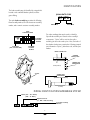
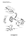
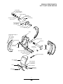
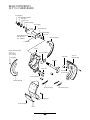
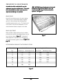
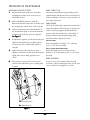
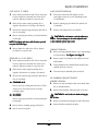
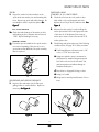
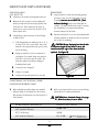
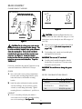
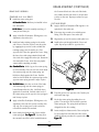
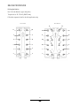
Dana®Spicer ® Brakes
16.5" Series S-Cam
XTRALIFE TM
XTRALIFE II TM
Cast
P-Series
Service Manual
BRSM-0890
October 1997
For the most current information, visit the Roadranger web site at www.roadranger.com
TABLE OF CONTENTS
Identification ..................................................................... 2
Brake Components (Standard/Xtralife) ...................... 3
Brake Components (Cast Series) .................................. 4
Brake Components (XL II Series) .................................. 5
Brake Components (“P” Series) .................................... 6
General Precautions ......................................................... 7
Preventative Maintenance ............................................... 9
Brake Disassembly ............................................................ 11
Inspection of Parts ........................................................... 12
Brake Assembly ................................................................. 15
Trouble Shooting Charts ................................................. 18
Reline Procedure ............................................................... 21
GENUINE SPICER SERVICE PARTS
Should a brake assembly require replacement component parts, it is recommended that Spicer
Brake Service Parts be used. Spicer Brake Service Parts are manufactured under the same rigid
specification as are original equipment brake components. This assures the customer who uses
genuine Spicer service parts, maximum reliability for a Spicer Brake assembly. They may be
obtained through your vehicle manufacturer. The use of non-original Spicer service parts may
cause premature compontent failure and may void the warranty.
The items included in this book are currently being offered as service parts at the time of
printing. The part numbers and illustrations are provided specifically for reference purposes
only. Therefore, Spicer reserves the right to update this manual without notice or liability.
i
IDENTIFICATION
The brake assembly may be identified by a tag which is
located on the camshaft bracket cylinder, near the
grease fitting.
JULIAN DATE CODE
97 170
The mylar brake assembly tag contains the following:
Dana assembly number, bar coded customer assembly
number, and a numeric customer assembly number.
MODEL YEAR
DAY OF YEAR
DANA
ASSEMBLY NUMBER
Two other markings that may be used to identify a
Spicer Brake assembly are located on the assembly's
components. "Spicer" will be cast into the spider
assembly just above the anchor pins. Also, the inside of
the chamber bracket arm contains the following stamped
part information: "Spicer", julian date code, and the part
number.
CUSTOMER
BAR CODE
NUMBER
Brake Assembly Tag
BUILD DATE
(APR 1997 AND LATER)
CUSTOMER
ASSEMBLY
NUMBER
BRAKE ASSEMBLY TAG
CHAMBER
BRACKET ARM
STAMPED PART
INFORMATION
Camshaft Bracket
"SPICER"
STAMPED PART
INFORMATION
(IN ONE OF THESE AREAS)
Spider
Camshaft
MODEL IDENTIFICATION NUMBERING SYSTEM
Model (165 = 16.5" Brake)
(150 = 15" Brake)
Alphabetical Code
(i.e., WD = Brake Assembly)
165
WD 000
Sequential Assembly
Numbers
0
2
BRAKE COMPONENTS
STANDARD/ XTRALIFE 16.5"
Retaining Ring
Camshaft Adjusting
Washers (Shims)
Camshaft Bushing
Grease Fitting
Steel Spacer
Grease Seal
Air Chamber
Bracket Assembly
Bracket Mounting Bolt
(70 - 80 Lb-Ft)
(95 - 108 N-m)
Lock Washer
Camshaft Bushing
Grease Seal
Dustshield Mounting Bolt
3/8 in. - 16
(20 - 28 Lb-Ft)
(27 - 38 N-m)
Lock Washer
Spider
Steel Spacer Plate
Camshaft
Cam Roller
Shoe Return Spring
Shoe and Lining
Assembly
Retainer Springs
Return Spring Pin
Lining
Brake Lining
Rivet
3
BRAKE COMPONENTS
16.5" CAST SHOE SERIES
Retaining Ring
Camshaft Adjusting
Washers (Shims)
Camshaft Bushing
Air Chamber
Bracket Assembly
Steel Spacer
Grease Seal
Grease Fitting
Bracket Mounting Bolt
(70 - 80 Lb-Ft)
(95 - 108 N-m)
Lock Washer
Camshaft Bushing
Grease Seal
Spider
Dustshield Mounting Bolt
3/8 in. - 16
(20 - 28 Lb-Ft)
(27 - 38 N-m)
Lock Washer
Dust Shield Half
Steel Spacer Plate
Camshaft
Anchor Pin
Retainer Clip
Anchor Pin
Retainer Clip
Washer
Cam Roller
Anchor Pin Bushing
Grease Fitting
Anchor Pin
Shoe and Lining
Assembly
Lining
Brake Lining
Bolt
Shoe Return Spring
Washer
Brake Lining Nut
(15-17 Lb-Ft)
(20-23 N-m)
Lock Washer
Brake Lining
Bronze Bushing
4
BRAKE COMPONENTS
16.5" XL II SERIES BRAKE
Retaining Ring
Camshaft Adjusting Washer
Steel Spacer
Grease Seal
Camshaft Bushing
Grease Fitting
Camshaft Bracket
Camshaft Bushing
Grease Seal
Bracket Mounting Bolt
(70 - 80 Lb-Ft)
(95 - 108 N-m)
Dust Shield (Half)
Lock Washer
Spider
Dustshield Mounting Bolt
3/8 in. - 16
(20 - 28 Lb-Ft)
(27 - 38 N-m)
Steel Spacer Plate
Cam Roller
Lock Washer
Camshaft
Anchor Pin
Cam Roller
Retainer Clip
Anchor Pin Bushing
Dust Shield (Half)
Shoe Return Spring
Return Spring Pin
Brake Lining Rivet
Lining
5
Shoe Retainer Spring
Shoe and
Lining Assembly
BRAKE COMPONENTS
16.5" P SERIES BRAKE
Retainer Ring
Camshaft Adjusting Washer
Steel Spacer
Grease Seal
Camshaft Bushing
Grease Fitting
Camshaft Bracket
Camshaft Bushing
Grease Seal
Bracket Mounting Bolt
(70 - 80 Lb-Ft)
(95 - 108 N-m)
Dust Shield (Half)
Lock Washer
Spider
Dustshield Mounting Bolt
3/8 in. - 16
(20 - 28 Lb-Ft)
(27 - 38 N-m)
Cam Roller
Retainer Clip
Steel Spacer Plate
Lock Washer
Camshaft
Anchor Pin
Washer
Snap Ring
Anchor Pin Bushing
Cam Roller
Dust Shield (Half)
Shoe Return Spring
Lining
Return Spring Pin
Brake Lining Rivet
6
GENERAL PRECAUTIONS
IMPOR
TANT
IMPORT
READ THIS SECTION BEFORE ST
AR
TING
STAR
ARTING
ANY SER
VICE PROCEDURES
SERVICE
Never remove a component or pipe plug unless you
are certain all system pressure has been depleted.
All Spicer original equipment or service parts for
steering and drive axle brakes are manufactured using
non-asbestos brake lining. It is recommended that
original Spicer service parts be used when brake maintenance is necessary.
SAFETY PRECAUTIONS
Proper service and repair of vehicle components is
important to the safe and reliable operation of all motor
vehicles. This applies particularly to brakes such as the
ones described in this manual. The procedures recommended and described in this manual are tested,
effective methods for performing service operation.
Follow each procedure closely, making use of both the
text and pictures. Some of these service procedures
show the use of certain tools designed especially for the
operation being performed. It is not mandatory that
these tools be used; they are shown only as preferred
means of performing the operation. It is not practical to
anticipate and advise the service trade of all possible
alternate service methods, and of all possible hazardous
consequences that could result from any particular
method. Accordingly, anyone who uses a service
procedure or tool different than shown must insure that
their safety, and that the vehicle’s safety will not be
jeopardized by the service method selected.
2.
Never exceed recommended air pressure and always
wear safety glasses when working with air pressure.
Never look into air jets or direct them at anyone.
4.
Never attempt to disassemble a component until
you have read and understand recommended
procedures. Some components contain powerful
springs and injury can result if not properly
disassembled. Use only proper tools and observe
all precautions pertaining to use of those tools.
5.
Use only genuine Spicer replacement parts and
components.
A. Only components, devices, mounting and
attaching hardware specifically designed for use
in air brake systems should be used.
B. Replacement hardware, tubing, hose, fittings, etc.
should be of equivalent size, type, length and
strength as the original equipment.
C. Make certain that when replacing tubing or hose,
all supports, clamps or suspending devices that
were originally installed by the vehicle manufacturer are reinstalled.
6.
CA
UTION: When w
orking on or ar
ound air
CAUTION:
working
around
br
ak
ems and component
s, the follo
wing
brak
akee ssyyst
stems
components,
following
pr
ecautions should be observ
ed:
precautions
observed:
1.
3.
Devices with stripped threads or damaged parts
should be replaced. Repairs requiring machining
should not be attempted.
CAUTION
Always block vehicle wheels. Stop engine when
working under a vehicle. Depleting vehicle air
system pressure may cause vehicle to roll. Keep
hands away from chamber push rods and slack
adjusters; they may automatically apply as system
pressure drops.
BRAKE LININGS CONTAIN NON-ASBESTOS FIBERS
BREATHING BRAKE DUST MAY BE HAZARDOUS TO YOUR HEALTH AND
MAY CAUSE SERIOUS RESPIRATORY OR OTHER BODILY HARM.
AVOID CREATING DUST
DO NOT REMOVE BRAKE DRUM WITHOUT PROPER PROTECTIVE EQUIPMENT.
DO NOT WORK ON LININGS WITHOUT PROPER PROTECTIVE EQUIPMENT.
DO NOT REPLACE LININGS WITHOUT PROPER PROTECTIVE EQUIPMENT.
DO NOT ATTEMPT TO SAND, GRIND, CHISEL, FILE, HAMMER OR ALTER BRAKE
LININGS IN ANY MANNER WITHOUT PROPER PROTECTIVE EQUIPMENT.
Never connect or disconnect a hose or line containing air pressure. It may whip as air escapes.
FOLLOW 0.S.H.A. STANDARDS FOR PROPER PROTECTIVE DEVICES TO BE USED
WHEN WORKING WITH BRAKE MATERIALS.
7
GENERAL PRECAUTIONS (CONTINUED)
PREPARATION
1.
Park vehicle on a level surface and prevent
movement by means other than the brakes.
5.
2.
If equipped with spring brakes, cage the spring on
all axles to be worked on.
3.
Raise the axle, to be worked on until the tires
clear the ground. Support axle with heavy duty
jack stands.
WARNING: The long tterm
erm effect
xposur
o noneffectss of eexposur
xposuree tto
ea
ting
a sbe
st
os ha
Avv oid cr
crea
eating
sbest
stos
hass no
nott been de
dettermined. A
dust when per
forming service on br
ak
ssemblie
s.
performing
brak
akee aassemblie
ssemblies.
xposur
o br
ak
aEx
ce
ssiv
xposuree tto
brak
akee dust ma
mayy cause rree spir
spiraExce
cessiv
ssivee eexposur
tory damage or oother
ther bodil
bodilyy harm.
4.
"Back-off " slack adjuster by turning adjusting nut
until the brake shoes are fully retracted.
Remove wheels and drums using the procedures
specified in the vehicle maintenance manual.
Safety glasses should be wor
n
worn
at all times when assembling
or disassembling brakes.
CA
UTION: RRockw
ockw
ell Aut
o Slacks rrequir
equir
wl
CAUTION:
ockwell
Auto
equiree the pa
pawl
a ssembl
o be rremo
emo
ssemblyy tto
emovv ed befor
beforee turning the adjust
adjust-ing nnut.
ut.
WARNING: Ne
ork under a vvehicle
ehicle suppor
Nevv er w
work
supportted
onl
and.
onlyy bbyy a jack. Alw
Alwaays use a jack st
stand.
8
PREVENTATIVE MAINTENANCE
A schedule should be eest
st
ablished for periodic
stablished
adjustment, inspection and lubrica
tion. This schedlubrication.
ule is de
om vvehicle
ehicle oowner/oper
wner/oper
dettermined fr
from
wner/operaa tor
orss
experience and the ttype
ype of oper
operaa tion
tion.
CA
UTION: Drums displa
ying hea
CAUTION:
displaying
heatt checks with
a contin
uous length of four inche
continuous
inchess or mor
moree and
ext
ends ar
ound the edge of the drum should be
xtends
around
replaced. See FFigur
igur
iguree 1.
BRAKE DRUMS
Inspect for heat checks, grooves, hot spots, glazing,
cracks, and out of round. Drums which are glazed,
grooved, or have moderate heat checking may be
resurfaced and returned to service. The drum should
not be used if it exceeds the manufacturer’s recommended maximum diameter stamped on the drum.
BRAKE ADJUSTMENT
Brakes should be adjusted whenever the air chamber
push rod stroke exceeds the maximum distance according to the chart shown in F igur
iguree 2
2. To determine if
brake adjustment is required measure the push rod
stroke with the brakes applied as shown in F igur
iguree 3 on
0.
page 1
10.
F igur
iguree 1
RECOMMENED AIR BRAKE ACTUATOR SERVICE STROKE
Chamber Size
Type
Standard Chamber
Rated Stroke
Long Stroke Chamber
Max Readjust Stroke
Rated Stroke
Max Readjust Stroke
12
1.75
1.38
2.00
1.50
16
2.25
1.75
2.50
2.00
20
2.25
1.75
2.50
2.00
24
2.25
1.75
2.50
2.00
30
2.50
2.00
2.75
2.25
36
3.00
2.25
-
-
Source: The Maintenance Council RP 635
F igur
iguree 2
9
PREVENTATIVE MAINTENANCE
BRAKE LUBRICTION
Lubricate the camshaft thru the grease fitting on the
camshaft bracket with the chassis lube specified by the
vehicle manufacturer. Lube once every six months or at
every chassis lubrication.
MEASURING PUSH ROD STROKE
1. Measure the distance between the air chamber
mounting face and the center of the clevis pin,
with brakes released.
2.
Make an 70-90 PSI application and hold it.
Measure the distance between the air chamber and
the mounting face and the center of the clevis pin.
3.
Subtract measurement A from measurement B. If
this measurement equals or exceeds the maximum
readjust stroke the brakes need to be adjusted.
See FFigur
igur
iguree 3.
4.
If adjustment is required, spin the wheel slowly and
adjust the slack adjuster just enough for wheel to
spin freely. Be sure to adjust brakes equally on
each axle.
5.
6.
BRAKE RELINE
The life of the brake lining is dependent on many factors
such as the material of the lining, type of operation the
vehicle is used for, geographic terrain, maintenance
practice of the shop, and the driver of the vehicle. If
driving conditions require frequent braking, lining
replacement will be required more often.
FOR RIVET LINING
Reline when thickness of lining is 1/4 " at thinnest
point, or 1/16" above rivet head.
FOR CAST SHOES WITH BOLTED LININGS
Reline when lining is below wear indicator line or
thickness is .31" at the thinnest point or 1/16" above
bolt head.
Apply and release brakes and observe slack
adjusters. Both slacks on each axle should respond
rapidly and in unison during application and
release.
BRAKE OVERHAUL
As often as necessary to maintain satisfactory brake
performance. When overhauling the brakes, provide equal
service to both the left and right side of an axle.
Drive vehicle at a low speed in a safe area and
check for brake effectiveness prior to putting back
in service.
B
A
A. Released Position
B. Applied Postion
FFigur
igur
iguree 3
10
BRAKE DISASSEMBLY
CAST SHOE & "P" SERIES
1. Insert sturdy lever between end of shoe and spider.
Pry shoe away from cam until cam rollers can be
removed. Repeat procedure for opposite shoe.
SLACK ADJUSTER REMOVAL
1. Disconnect clevis from slack adjuster arm by
removing the clevis pin or pins depending on type
of slack adjuster.
2.
Unhook shoe return spring by pushing shoes
together, allow tension on spring to be reduced.
2.
Remove retaining ring and shims from splined end
of camshaft.
3.
Discard shoe return spring and replace with new at
time of reassembly.
3.
Remove slack adjuster from the camshaft.
4.
Remove snap ring from anchor pin and push anchor
pin through.
CA
UTION: Do no
er tto
o
CAUTION:
nott hammer on slack adjust
adjuster
remo
o the slack adjust
er and/
emovv e. Serious damage tto
adjuster
or the camshaft spline
spliness ma
mayy rree sult.
NO
TE: T
ap lightl
NOTE:
Tap
lightlyy with br
braa ss drift if anchor pin will
no
nott push out with finger
finger..
5.
Remove brake shoe and place on floor. Repeat
procedure for opposite shoe.
CAMSHAFT REMOVAL
1. Before removing camshaft check to see if cam bushings
age 1
2.
igur
need replacement. See FFigur
iguree 4 on PPage
12.
STANDARD, XL, & XLII SERIES
1. Insert sturdy lever between end of shoe and spider.
Pry shoe away from cam until cam rollers can be
removed. Repeat procedure for opposite shoe.
2.
Unhook shoe return spring by pushing shoes
together, allow tension on spring to be reduced.
3.
Discard shoe return spring and replace with new at
time of reassembly.
2.
Remove spacer from between slack adjuster and cam
shaft bracket.
3.
Grasp camshaft at the camshaft head and pull in the
outward direction to remove.
4.
Clean and inspect camshaft splines and head.
AIR CHAMBER/ CAMSHAFT BRACKET
ASSMEBLY REMOVAL
1. Remove two nuts and washers that secure brake chamber to camshaft bracket.
4a. S TAND
ARD & XL
ANDARD
Remove shoes by rotating the bottom shoe off the
anchor pin to release the tension on the two
retaining springs.
2.
Remove brake chamber and temporarily set it aside.
CA
UTION: Do no
CAUTION:
nott le
lett the air chamber hang bbyy
the air line
liness
4b. XLII SERIES
Remove snap ring from anchor pin and push anchor
pin through.
3.
Remove four bracket mounting bolts and lock washers.
5.
Remove the two retaining springs and discard.
4.
Remove bracket assembly from spider.
6.
Remove shoes from spider.
11
BRAKE DISASSEMBLY (CONTINUED)
SPIDER REMOVAL
1. Mark the postion of the spider on the axle (L.H. or
R.H.) and the orientation on the axle flange by
making a reference mark on the spider and flange.
See FFigur
igur
iguree 4.
2. Remove the spider to axle mounting bolts.
3. Remove spider.
DUST SHIELD REMOVAL
1. Mark dust shields (upper left, lower right, etcprior to removal.
2.
Detach dust sheild by removing the six cap screws
using a 9/16" socket. Do not remove dust shield
unless there is apparent damage.
F igur
iguree 4
INSPECTION OF PARTS
AIR CHAMBER BRACKET ASSEMBLY
1.
Check assembly for bent chamber bracket, broken
welds, cracks, and correct alignment.
2.
Inspect camshaft bushings for signs of wear.
Bearing surfaces should be smooth and free of any
pitting or fractures. Insert camshaft and measure
looseness up and down side to side at both ends
with a dial indicator. If more than .030” movement,
igur
replace bushings and/or camshaft. See FFigur
iguree 5.
F igur
iguree 6
equir
thatt a bushing rrequir
equiree s
NOTE:
dettermined tha
NO
TE: If it is de
r eplacement, bo
th camshaft bushings and seals
both
should be rreplaced.
eplaced. All CAS
T SHOE and P SERIES
CAST
br
ak
onze cam bushings. The SST
TAND
ARD,
brak
akee s ha
havve br
bronze
ANDARD,
XL, and XLII SERIES br
ak
ylon bushings with
brak
akee s use nnylon
the br
onze bushing aass an op
tion.
bronze
option.
CAMSHAFT
1. Inspect camshaft spline and body for chips and
excessive deformation. Replace as necessary.
See FFigur
igur
iguree 6.
2.
Inspect cam head for cracks, and its roller surfaces
for flat spots, brinneling, or ridges.
NO
TE: Un
usual w
ear pa
NOTE:
Unusual
wear
pattterns which ma
mayy indica
indicatte an
out
-of-squar
eplace damaged camout-of-squar
-of-squaree condition. RReplace
shaft
s.
shafts.
F igur
iguree 5
12
INSPECTION OF PARTS
SPIDER
1. Inspect for cracked or broken surfaces on the
spider at the cam, anchor pins, and mounting bolt
holes. Replace any spider with visible damage. Do
not attempt to weld or repair the spiders. See
F igur
iguree 7
7..
SHOES AND LINING
STANDARD, XL, XL II AND P SERIES
1. Check shoes for bent shoe ribs, cracks in shoe
table welds or ribs, and elongated rivet holes.
Replace shoes if any of these conditions exist. See
F igur
iguree 9.
XLII, P, & CAST SHOE SERIES
2.
Measure the shoe span by loosely installing the
anchor pin and cam roller in the appropriate ends
of the shoe rib. If the distance from center of
anchor pin to center of cam roller exceeds 12.76
inches replace shoe.
3.
Check linings and replace when any of the following
conditions exist: See page 21 for reline procedure.
2a
2a. Check the inside diameter of the anchor pin hole
with bushing in place. Diameter must not exceed
1.282”. Replace bushing if necessary.
STANDARD & XL SERIES
2b. The anchor pins are staked into the spider and are
not serviced separately. If the pins are loose or
grooved more than .030 inch, the spider assembly
must be replaced.
A. Total lining thickness at thinnest point is 1/4"
or less, or 1/16" above the rivets.
B. Linings are cracked or worn in an unusual or
odd pattern. For example: lining wear tapered
from side to side across the shoe table. Un
usual wear pattern can indicate damage to
foundation brake parts.
C. Rivet holes are elongated in lining or shoes.
D. Lining is oil soaked.
F igur
iguree 7
E. Linings can be moved by hand because of loose
rivets.
ROLLERS AND ANCHOR PINS, BUSHINGS
1. Inspect rollers and anchor pins for flat spots,
galling, broken or cracked surfaces. Replace as
igur
necessary. See FFigur
iguree 8.
F igur
iguree 9
F igur
iguree 8
13
INSPECTION OF PARTS (CONTINUED)
SHOES AND LINING
CAST SHOE TYPE
1. Check shoes for cracks and elongated bolt holes.
2.
Measure the shoe span by loosely installing the
anchor pin and cam roller in the appropriate ends
of the shoe rib. If the distance from center of
anchor pin to center of cam roller exceeds 12.76
inches replace shoe.
3.
Check linings, replace when any of the following
conditions exist.
BRAKE DRUMS
1. Inspect drums for cracks, heat checking, glazing,
grooving, severe out-of-round condition or bell
25 T
.I.R. (T
o tal
mouthing m ust no
nott eexx ceed .0
.02
T.I.R.
(To
Indica
eading) Replace any drums that are
Indicattor RReading)
cracked. The drum should not be used if it exceeds
the manufacturer’s recommended maximum
diameter stamped on the drum.
2.
A. Total lining thickness at thinnest point is .31” or
less than 1/16” above screw head. Also, if the
material is worn beyond the wear groove on the
side of the lining.
B.
Linings are cracked or worn in an unusual or
odd pattern. For example: lining wear tapered
from side to side across the shoe table. Un
usual wear pattern can indicate damage to
foundation brake parts.
C.
Screw holes are elongated.
D.
Lining is oil soaked.
E.
Lining can be moved by hand. (loose bolts)
Measure the drum I.D. to be sure the maximum limit
allowed (stamped on drum) has not been exceeded
due to wear or machining.
CA
UTION: Drums displa
ying hea
CAUTION:
displaying
heatt checks with
a contin
uous length of four inche
continuous
inchess or mor
moree and
ext
end ar
ound the edge of the drum should be
xtend
around
replaced. See FFigur
igur
0.
iguree 1
10.
F igur
0
iguree 1
10
TRANSIT BRAKE (CAST SHOE ONLY) DRUM/
LINING CROSS REFERENCE CHART
1.
2.
When installing new drums always use standard
thickness lining. If used drums are rebored carefully measure inside diameter (in several places) of
rebored drum.
Refer to the chart below for proper oversized lining
required based on drum measurements.
CA
UTION: Ne
ak
CAUTION:
Nevver shim br
brak
akee linings. See page
eline Pr
ocedur
e, for mor
21, RReline
Procedur
ocedure,
moree de
dettail.
LINING MAXIMUM THICKNESS (IN)
DRUM DIA. (IN) AT RELINE
.867” (Standard Thickness)
16.500”- New
.927” (1X Oversize)
16.620”
.987” (Premium Thickness)
Over 16.620”
14
CAUTION: Maximum discard
diameter is 16.750”
BRAKE ASSEMBLY
CHAMBER BRACKET ASSEMBLY
Seal Installation
NO
TE: Bo
th lip seals point the same
NOTE:
Both
dir
ection, lip tto
ow ar
d the slack adjust
er
direction,
ard
adjuster
Left Hand Cam
Right Hand Cam
Lip Seal
Lip Seal
F igur
2
iguree 1
12
End Cam
Slack A
djust
er End
Adjust
djuster
CA
UTION: Left Hand and Right Hand does not
CAUTION:
establish which side of the vehicle the cam goes on. Left
and right are used to identify the two different types of
cams only.
A ctua
ack
ctuattor Br
Brack
ackee t
and Cam T
ube
Tube
Spider
F igur
1
iguree 1
11
CA
UTION: The lip of the gr
ea
se seals m
ust be
CAUTION:
grea
ease
must
inst
alled corr
ectl
o pr
installed
correctl
ectlyy tto
preev ent posssible damage. The
lip of the seal tha
alled in the spider end m
ust
thatt is inst
installed
must
ent
er the opening fir
st. The lip of the seal tha
enter
first.
thatt is
ust
inst
alled in the opposit
oppositee end of the cam tube m
must
installed
all the chamber
ent
er la
st. See FFigur
igur
1. Inst
Install
enter
last.
iguree 1
11
ssembl
o the spider
br
ack
ssemblyy ont
onto
brack
ackee t and the cam tube aassembl
using four cap scr
s. T
or
que tto
o
scree ws and lockw
lockwaa sher
shers.
Tor
orque
70-8
0 Lb-Ft.
0-80
3.
Coat bushing, seals, journals and camshaft spline
with light film of chassis lube.
4.
Carefully install camshaft through the chamber
bracket tube, from spider end. Cam must rotate
freely when turned by hand.
IMPOR
TANT
eful no
o damage the gr
ea
se
IMPORT
ANT:: Be car
careful
nott tto
grea
ease
seals.
SPIDER
1. Use a wire brush to remove heavy contamination
from the spider mounting flange, knuckle, spider,
brake drum exterior, and chamber mounting
bracket.
SPICER S-CAM BRAKE RETURN SPRINGS
Br
ak
Brak
akee Serie
Seriess
Install the spider and chamber bracket assembly
onto the axle flange. Be sure spider is properly
oriented, as noted during disassembly. Tighten
mounting fastener to manufacturer's specifications.
CAMSHAFT
1. Prior to reassembly, verify the part number is
correct there are L.H. and R.H. camshafts and they
igur
2.
can not be interchanged. See FFigur
iguree 1
12.
Place steel spacer plate over splined end and slide
ak
next to cam head. (See br
brak
akee component
componentss on
page
pagess 3-6)
IMPOR
TANT
IMPORT
ANT:: Do no
nott coa
coatt "S" cam head.
If removed, reinstall the dust shields. Tighten the six cap
screws and lockwashers to 20-28 Lb-Ft of torque.
2.
2.
15
Re turn Springs P/N & Color
Standard
165WJ110 Dark Blue
XL & Cast Shoe
165WJ115 White
XLII
165WJ129 Light Blue
BRAKE ASSEMBLY (CONTINUED)
BRAKE SHOE ASSEMBLY
the S-cam and the slots in the end of the brake
shoe. Make sure the cam rollers are in the lowest
position on the cam. Repeat procedure for opposite side.
STANDARD, XL & XL II SERIES
1. Install new return spring pins:
A. St
andar
d Serie
Standar
andard
Seriess - Wireform pin installed in shoe
ribs with mallet.
CAST SHOE SERIES
1. Apply a thin film of Lubriplate 630-A grease or its
equivalent to the anchor pin.
B. XL Serie
Seriess - 2 piece kit assembly consisting of
inner pin and outer pin.
2.
3.
Apply a thin film of Lubriplate 630-A grease or its
equivalent to the anchor pin.
Install new brake retaining springs in the anchor
end of shoes. Place the top shoe onto the spider
by engaging the open slots on the end with the
retaining springs onto the anchor pin. Place
opposite end of the shoe against the S-cam. Swing
the lower shoe, with springs attached, back until
slots in the shoe engage the anchor pin. Rotate the
shoe toward the S-cam. Lower shoe may require
support while completing assembly.
2.
Place snap ring on anchor pin end with grease
fitting. Place thin spacer onto anchor pin.
3.
Align anchor pin end of cast shoe with spider bore.
4.
Install anchor pin through backside of shoe and
spider. Repeat procedure for opposite shoe.
4a. St
andar
d Serie
Standar
andard
Seriess - Utilize leg on shoe return spring
to aid in assembly. Place the one hook of the brake
shoe return spring onto the return spring pin.
Hold shoes firmly against the S-cam. Push the
other hook of the brake shoe return spring over the
opposite return spring pin until it snaps in place.
4b. XL/XL II Serie
Seriess - place the one hook of the brake
shoe return spring onto the return spring pin
located between the shoe ribs. Hold both shoes
against the S-cam head. Push the other hook of
the return spring over the opposite shoe spring pin
until it snaps in place.
5.
Apply a thin film of Lubriplate 630-A grease or its
equivalent to the cam roller journal, and the roller
side only. Do not put grease on the end of the
roller which contacts the cam head.
6.
Insert sturdy lever between end of shoe and the
igur
3 . Pry away from
return spring pin. See FFigur
iguree 1
13
the cam until cam rollers can be installed between
F igur
3
iguree 1
13
16
5.
Place thin spacer onto opposite side of anchor pins
and install snap rings.
6.
Hook shoe return spring by pushing shoes together. The cast shoe does not have a separate
return spring pin. The spring hook-up feature is
designed into the shoe casting.
7.
Insert sturdy lever between end of shoe and spider.
Pry shoe away from cam until cam rollers can be
installed. Repeat procedure for opposite side. See
F igur
3.
iguree 1
13.
BRAKE ASSEMBLY (CONTINUED)
“P” SERIES
1 . Install new return spring pins. See FFigur
igur
4.
iguree 1
14.
2.
Align lower end of fabricated shoe with spider bore.
3.
Place snap ring on anchor pin end with grease
fitting. Place thin spacer onto anchor pin.
4.
Install anchor pin through backside of shoe and
spider.
5.
Apply a thin film of Lubriplate 630-A grease or its
equivalent to the anchor pin.
6.
Place thin spacer onto opposite side of anchor pin
and install snap ring.
7.
Hook shoe return spring by pushing shoes together.
8.
Insert sturdy lever between end of shoe and spider.
Pry shoe away from cam until cam rollers can be
installed. Repeat procedure for opposite side.
F igur
4
iguree 1
14
NO
TE: Due tto
o the man
tions of slack
NOTE:
manyy combina
combinations
ak
s, follo
w vvehicle
ehicle
adjust
er
adjuster
erss and br
brak
akee chamber
chambers,
follow
man
ufactur
er’
tions and pr
ocedur
manufactur
ufacturer’
er’ss specifica
specifications
procedur
oceduree s for
a ssembl
ssemblyy and final adjustment.
SLACK ADJUSTER ASSEMBLY
1. Reinstall thick camshaft flatwasher.
3.
Spin the wheel slowly and adjust the slack adjuster
until wheel will no longer turn. Back off slack
adjuster just enough for wheel to spin freely. Be
sure to adjust brakes equally on each axle.
2.
Install new slack adjuster, shims, and a new snap
ring (In that sequence) into the splined end of the
camshaft.
3.
Adjust camshaft end play of the camshaft to
between .005" and .045" by using the appropriate
number of shims. Make sure the snap ring is seated
into the groove at the end of the splined camshaft.
4.
Apply the release brakes and observe slack adjusters. Both slacks on each axle should respond
rapidly and in unison during application and
release.
BRAKE LUBRICATION
1. Lubricate the camshaft bushings by filling the
camshaft tube with lube through the zerk fitting
provided. Fill until grease is forced out in the area
of the slack adjuster. Grease should not appear at
the cam head end. If it does, the seal has not been
properly installed, or the old seals should be
replaced.
5.
Drive vehicle at a low speed in a safe area and
check for brake effectiveness prior to putting back
in service.
2.
Reinstall brake drums and wheels. Torque and
adjust wheel bearings to manufacturer’s specifications.
17
FOUNDATION BRAKE TROUBLESHOOTING CHART
SYMPTOM
1. Degraded brake
performance.
CAUSE
REMEDY
A. Too much push rod free travel.
A. Adjust brake.
B. Severely glazed or worn out linings.
B. Deglaze linings or replace.
C. Grease or oil on linings.
C. Replace linings.
D. Worn, seared, heat checked, cracked
drums.
D. Replace part.
E. Push rod length too long.
E. Adjust clevice, shorten push rod length
F.
F.
Air chamber in wrong position.
Reposition.
G. Broken or bent parts.
G. Replace part.
H. Flat spots on cam or rollers.
2. Slow brake
application.
A. Cam shaft bushings binding.
H. Replace flat-spotted parts.
A. Clean and lubricate. Check for seal
leakage.
3. Slow brake release.
A. Binding cam shaft and bushing.
A. Clean and lubricate.
B. Weak or broken shoe return
spring.
B. Replace part.
C. Replace flat-spotted parts.
C. Flat spotted cam or rollers.
4. Grabbing or pulling.
A. Grease, oil, or dirt on linings.
A. Replace lining.
B. Glazed linings.
B. Deglaze lining or replace.
C. Brake linings not a balanced set,
different friction codes, or lining brand.
C. Replace linings.
D. Loose or broken linings.
D. Replace linings.
E. Brake drum out-of-round.
E. Turn, per manufacturer's specifications.
F.
F.
Defective brake drum.
Replace part.
G. Clevis pin or camshaft binding at one
or more wheels.
G. Clean and lubricate.
H. Defective slack adjuster.
H. Replace part.
I.
Uneven brake adjustment (side to side).
I.
Adjust brakes.
J.
Broken or bent parts.
J.
Replace part.
K. Loose spider or drum mounting bolts.
K. Inspect and replace as necessary.
L. Different air chamber size or slack
adjuster length (side to side).
L. Use same size and type both ends of
the axle.
18
BRAKE SHOE & LINING TROUBLESHOOTING CHART
SYMPTOM
1. Poor lining to drum
contact.
2. Linings tapered
across width.
3. Unequal wear on
same brake.
4. Unequal wear side
to side brakes,
same axle.
5. Wear on edge of
lining.
6. Glazed linings
(hard & shiny).
CAUSE
REMEDY
A. Bell-mouth drum.
A. Replace part.
B. Bent brake spider.
B. Replace part.
C. Bent or stretched brake shoe.
C. Replace part.
D. Undersize linings.
D. Replace linings.
E. Loose wheel bearing.
E. Correct as required.
F.
F.
Improper lining grind.
Regrind linings to drum
radius minus .015"
A. Bell-mouth drum.
A. Replace parts.
B. Bent brake shoe.
B. Replace parts.
C. Bent brake spider.
C. Replace part.
D. Loose wheel bearings.
D. Correct as required.
A. Mismatched lining friction codes.
A. Replace linings.
B. Stretched shoe.
B. Replace parts.
C. Flat spots on cam or roller.
C. Replace flat-spotted parts.
D. Worn anchor pin.
D. Correct as required.
E. Worn camshaft or bushings.
E. Replace part.
A. Mismatched lining friction codes.
A. Replace linings.
B. Seized or binding camshaft.
B. Clean and lubricate.
C. Brake drum surface
in poor condition.
C. Replace or turn I.D.
D. Loose wheel bearing.
D. Correct as required.
E. Relining one brake.
E. Reline both brakes together.
A. Wrong width lining.
A. Replace linings.
B. Holes improperly drilled in lining.
B. Replace linings.
C. Wrong drum, or improperly machined.
C. Replace or turn I.D.
D. Loose wheel bearing
D. Correct as required.
E. Improper wheel bearing or cone.
E. Correct as required.
F.
F.
Bent brake shoe.
Replace part.
G. Bent brake spider.
G. Replace part.
H. Worn axle spindle.
H. Correct as required.
A. Overheating, due to unbalanced
braking system.
A. Correct as required.
B. Wrong type linings for service
involved.
B. Replace linings.
19
BRAKE SHOE AND LINING TROUBLESHOOTING CHART
7. Scored or grooved
linings and drum.
8. Loose lining.
9. Cracked lining at
rivet holes.
10. Elongated rivet
holes.
A. Scored or worn drum, not
machined at reline.
A. Replace or re-machine.
B. Abrasive material between
lining and drum.
B. Clean, remove dirt and debris.
A. Improper size rivets (too long, too
short, improper diameter).
A. Re-rivet.
B. Improper crimping of rivet.
B. Re-rivet.
C. Enlarged rivet holes in shoe.
C. Replace part.
D. Incorrect lining hole size or counter
bore depth.
D. Replace linings.
E. Rust build up on shoe table.
E. Clean, remove rust and paint shoe.
A. Wrong type rivets.
A. Replace part.
B. Rivets not properly crimped.
B. Replace lining.
C. Dirt or rust on shoe table.
C. Clean, remove dirt and debris.
D. Wrong size lining counter bore.
D. Replace linings.
A. Loose rivets.
A. Replace shoe and lining.
BRAKE DRUM TROUBLESHOOTING CHART
SYMPTOM
1. Brake drum heat
checked.
2. Excessive scoring
of drum.
CAUSE
A. Out round brake drum.
REMEDY
A. Turn, per manufacturer’s specifications.
B. Eccentric mounting of drum.
B. Inspect wheel and drum and replace
defective part.
C. Loose wheel bearing.
C. Correct as required.
D. Glazed linings.
D. Replace linings.
E. Improper friction materials for duty
cycle of vehicle.
E. Consult vehicle manufacturer.
F. Overworked brake.
F. Check proper brake balance.
G. Driver abuse.
G. Correct as required.
H. Wrong drum, too light.
H. Replace part.
A. Defective brake lining.
A. Replace linings.
B. Abrasive material between lining and
drum.
B. Clean, remove dirt and debris.
C. Soft drum.
C. Check hardness on flange.
D. Excessive lining wear, rivets contact
ing drum.
D. Replace lining.
E. Drum not turned at last reline.
E. Turn per manufacturer’s specifications.
F. Build up of abrasives in rivet holes.
F. Blow out debris.
20
RELINE PROCEDURE
Bolts/Rivets Removal
When removing bolts/rivets from the brake shoes, be
careful to avoid doing any damage to the holes in the
shoe. Do not use a chisel to shear them off. The force
will elongate the bolt/rivet holes. Neglecting any
elongated holes may result in a loose fitting installation.
If holes are burred, they should be filed down flush with
the shoe table.
Cleaning the Shoe
Rust often developes on the surface of the shoe table
under the brake lining or blocks. During every reline job,
shoe tables should be cleaned thoroughly. The best
procedure is to steam clean the entire shoe or put it into
a degreaser.
F igur
6
iguree 1
16
The installation should be checked by attempting to
insert a .006" feeler gage between the lining and shoe
table. It should not be possible to insert the feeler gage
6. The only
igur
iguree 1
16.
anywhere along the edge. See FFigur
exception is at each end and beyond the last row of
rivets/bolts. A slightly larger clearance may exist in
these areas.
After cleaning the shoe, the shoe should be scraped
clean of rust and scale. Any burrs or nicks should be
filed smooth. At the same time, the entire shoe should
be examined to see if it is worn or bent.
Shoe Inspection
The shoe should be either reconditioned or discarded.
It is also necessary to check for flat spots on the shoe
that can be caused by cleaning away the rust from the
area that was under the block previously. This can cause
a mismatch of shoe and lining arcs. After the shoe is
cleaned and inspected, it should be given a coating of
rust preventative paint. Treatment of a new, unpainted
shoe is also suggested to prevent the initial rusting
problem.
Riveting Application
Some brake failures result from the use of rivets which
are too short, too long, or the wrong diameter. Incorrect setting of the riveting machine may induce other
types of failures.
The solid portion of the rivet should end just at the
inner surface of the shoe. The hollow portion of the
rivet should extend past the inner surface of the shoe.
The proper size rivet must be used to completely fill the
hole.
Lining Installation
IMPOR
TANT
ak
IMPORT
ANT:: Ne
Nevv er shim the br
brak
akee linings. Brake
noise may result because of cracked and/or loose lining
since a tight installation is not possible with shims. The
inside surface of the correct arc to match the shoe table,
and the rivet/bolt holes in the linings will only line up
with holes in the shoes when they are in direct contact.
Prior to riveting/bolting be sure the holes in the lining
blocks and the shoes are exactly matched.
The sequence of riveting/bolting should be such that
the center of the block is attached first and then the
2 for bolting sequence.
ends. See page 2
22
USE ONL
Y1
0-81/2 RIVETS
ONLY
10-8
Brass plated steel rivets are recommened. The riveting
machine must be adjusted so that the roll of the rivet is
complete, but the rivet should not split. Always use a
roll set, never a star set, when riveting brake linings. A
star set does not compress the rivet and expand it to fill
the hole. Consequently, the lining may work loose in
service.
21
RELINE PROCEDURE
Bolting Application
Use 3/8 inch diameter copper alloy bolts.
Torque bolts to 15-17 Lb-Ft (20-23 N-m)
Follow the sequence below for the bolt application only.
16.5 x 6 inch
16.5 x 10 inch
15
11
10
17
7
8
11
9
12
14
19
13
20
18
3
5
4
10
1
2
1
6
7
22
6
8
2
5
3
12
16
4
9
Copyright Eaton and Dana Corporation,
2002. EATON AND DANA CORPORATION
hereby grants its customers, vendors, or
distributors permission to freely copy,
reproduce and/or distribute this document
in printed format. THIS INFORMATION IS
NOT INTENDED FOR SALE OR RESALE, AND THIS NOTICE MUST REMAIN
ON ALL COPIES.
The Roadranger® System is an unbeatable combination of the best
products from Eaton and Dana -- partnering to provide you the most
advanced, most trouble-free drivetrain in the industry. And it's
backed by the Roadrangers -- the most experienced, most expert,
most accessible drivetrain consultants in the business. Visit our web
site at www.roadranger.com. For spec'ing or service assistance,
call 1-800-826-HELP (4357) 24 hours a day, 7 days a week,
(Mexico: 001-800-826-HELP (4357)) for more time on the road.
BRSM-0890
05/04 PDF
Printed in USA