1
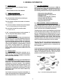
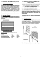
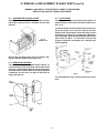
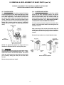
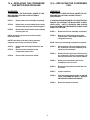
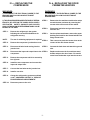
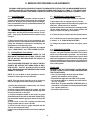
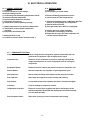
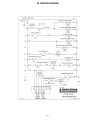
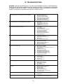
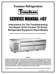
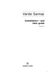
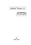
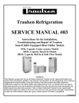
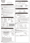
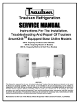
Traulsen Refrigeration
SERVICE MANUAL #05
Instructions For The Troubleshooting And
Repair Of Traulsen R-Series
Even-Thaw Refrigerator Models
RET232NUT-FHS & RET232NUT-HHS
-NOTICEThis Manual is prepared for the use of trained Authorized Traulsen Service Agents and should not be used
by those not properly qualified. This manual is not intended to be all encompassing, but is written to
supplement the formal training, on-the-job experience and other product knowledge acquired by Authorized Traulsen Service Agents. Before proceeding with any work, you should read, in its entirety, the repair
procedure you wish to perform to determine if you have the necessary tools, instruments and skills required
to perform the procedure. Procedures for which you do not have the necessary tools, instruments and
skills should be performed only by a trained Authorized Traulsen Service Agent.
Reproduction or other use of this Manual, without the express written consent of Traulsen, is prohibited.
FORM NUMBER TR35845 - REVISED. 12/04
TABLE OF CONTENTS
I. THE SERIAL TAG
1
II. GENERAL INFORMATION
a.
b.
c.
d.
e.
f.
g.
h.
i.
j.
k.
Introduction
Model Designations
Wiring Diagrams
Installation - See Owner’s Manual
Cleaning
Tools
Refrigeration System Theory Of Operation
Air Flow Requirements
Control Location
Specifications
Operating Data Chart
2
2
2
2
2
2
2
3
3
3
3
III. REMOVAL & REPLACEMENT OF PARTS
a.
b.
c.
d.
e.
f.
g.
h.
Standard Incandecent Lights
Louver Assembly
Evaporator Housing Cover
Removing The Door
Door Hinge
Snap-In Door Gaskets
Condensate Drain Pan
Door Breaker Caps
3
3
4
4
4
5
5
5
V. SERVICE PROCEDURES & ADJUSTMENTS
a.
b.
c.
d.
e.
f.
g.
h.
System Access
Sweat On Piercing Valves
Refrigerant Leak Check
Evacuating System
Charging System
System Clean-up
Heater Test/Door Perimeter Heater
Heater Test/Defrost Heater
8
8
8
8-9
9
9-10
10
10
VI. ELECTRICAL OPERATION
a.
b.
c.
Sequence Of Operation/Normal Operation
Sequence Of Operation/Defrost Mode
Component Function
11
11
11
VII. WIRING DIAGRAMS
12
VIII. PARTS LISTING
13
IX. TROUBLESHOOTING
14
IV. REPLACING THE...
a.
b.
c.
d.
CONDENSER FAN MOTOR AND/OR BLADE
CONDENSER COIL
COMPRESSOR
DOOR BREAKER CAPS
6
6
7
7
For Questions Please Contact Traulsen Service At:
(800) 825-8220
I. THE SERIAL TAG
The serial tag is a permanently affixed sticker on
which is recorded vital electrical and refrigeration data
about your Traulsen product, as well as the model
and serial number. This tag is located in the upper
right interior compartment on all reach-in/pass-thru
and roll-in/roll-thru refrigerator, freezer and dual-temp
models.
FORT WORTH, TX.
SERIAL
VOLTS
MODEL
Hz
PH
TOTAL CURRENT
AMPS
MINIMUM CIRCUIT
AMPS
MAXIMUM OVERCURRENT PROTECTION
LIGHTS
WATTS
HEATERS
AMPS
AMPS
REFRIGERANT
DESIGN PRESSURE
TYPE
HIGH
OZ
LOW
REFRIGERANT
DESIGN PRESSURE
TYPE
HIGH
OZ
LOW
370-60294-00 REV (A)
-1-
READING THE SERIAL TAG
• Serial = The permanent ID# of your Traulsen
• Model = The model # of your Traulsen
• Volts = Voltage
• Hz = Cycle
• PH = Phase
• Total Current = Maximum amp draw
• Minimum Circuit = Minimum circuit required
• Lights = Light wattage
• Heaters = Heater amperage
• Refrigerant = Refrigerant type used
• Design Pressure = High & low side operating
pressures and refrigerant charge
• Agency Labels = Designates agency listings
II. GENERAL INFORMATION
II. a - INTRODUCTION:
This manual applies to the following Traulsen
product types:
II. f - TOOL REQUIREMENTS:
For most jobs a standard set of hand tools, a VOM and
AC current tester, along with a temperature tester or
thermometer are adequate. However in some cases
the following additional tools may be required as well:
R-Series Reach-In Even-Thaw Models
II. b - MODEL DESIGNATIONS:
The first letter indicates the series, “R”
•
•
•
•
•
•
•
R = Stainless Steel Exterior & Interior
The next two letters indicate the product type
ET = Even-Thaw Refrigerator
The first number indicates the number of sections
2 = Two Section
Refrigeration Guage Manifold
Refrigeration Reclaiming Equipment
Acetylene Torch
Anti-Static Grounding Kit (TL 84919)
Nitrogen Bottle With Gauges
Thin 5/16” Open End Wrench
Refrigerant Reclaim Unit
II. g - REF’N SYSTEM - THEORY OF OPERATION:
The refrigeration system is the mechanism whereby
heat is transferred from the cabinet to the outside air.
It works under the principle that the heat moves from
hot to cold as it tries to establish equilibrium.
The next two numbers indicates the product depth
32 = 32” Deep Over Body (not including hardware)
The next letter indicates the product width
N = 2 Section: 52-1/8”
The temperature control control signals a need for heat
to be removed from the cabinet. The compressor begins by compressing the refrigerant gas as it is discharged. The high pressure refrigerant now circulates
through the condenser, removing heat from the refrigerant and condensing it into a liquid. From there the
refrigerant flows to the filter drier which removes all
traces of moisture and particles from the system.
If “UT” is present the product is self-contained. If
“UT” is not present the product is remote.
II. c - WIRING DIAGRAM:
Refer to the wiring diagram for any service work performed on this unit. The copy contained in this booklet is for standard 115/60/1 voltage, self-contained,
incandescent light equipped models only. Other voltages and feature/options sets are not necessarily
covered by the diagrams contained within. Should
you require a wiring diagram for a specific unit,
please contact Traulsen Service at (800) 825-8220,
and provide the model and serial number of the unit
involved.
After the filter drier, the refrigerant passes through a
“metering device.” Traulsen uses a thermostatic expansion valve to regulate the flow of refrigerant into
the evaporator coil.
In the evaporator coil, heat is transfered from the cabinet to the refrigerant, which changes from a cold liquid to a warm low pressure gas. When the desired
cabinet air temperature has been reached, the temperature control shuts off the compressor.
II. d - INSTALLATION:
Generally R-Series refrigeration products are installed by the dealer or others contracted by the
dealer or owner. Detailed installation instructions
are included with each unit.
II. e - CLEANING:
Detailed cleaning instructions are included with each
unit, however special care MUST be given to the condenser coil. The condenser coil must be cleaned at
a minumum of every six months. Your particular
application may require more frequent intervals. This
can be done with a vacuum cleaners using a brush
attachment, or a stiff brush or wisk broom. For more
information please refer to the Owner’s Manual supplied with the unit.
Your Traulsen unit may incorporate a washable, reusable wire mesh filter on the condensing unit. Clean
it with soap and water or in a dishwasher.
Fig. 1 - The Traulsen Refrigeration System
-2-
II. GENERAL INFORMATION (cont’d)
III. REMOVAL & REPLACEMENT OF
BASIC PARTS
II. h - AIR FLOW REQUIREMENTS:
In order to assure optimum performance, the condensing unit of your Traulsen unit MUST have an adequate
supply of air for cooling purposes. Therefore, the operating location must either have a minimum of 12”
clearance overhead of the condensing unit or allow
for unrestricted air flow at the back of the unit. The
louver panel must remain free and clear of obstruction. The condenser coil must be kept clean (see II. e).
WARNING: DISCONNECT THE ELECTRICAL POWER
TO THE MACHINE AT THE MAIN CIRCUIT BOX.
PLACE A TAG ON THE CIRCUIT BOX INDICATING
THE CIRCUIT IS BEING SERVICED.
III. a - STANDARD INCANDESCENT LIGHTS:
Lights are usually located in the front center of the unit,
mounted on the interior top. To replace the light bulb,
first remove the light cover by squeezing the sides together, which releases the tabs from the holding slots.
Replace the burned out light bulb with a similar type
appliance bulb.
Please note that clearance of at least 12” above is required in order to perform certain maintenance tasks.
To replace the light cover, squeeze the sides together
and reinsert tabs in to the holding slots and release to
lock in place.
II. i - CONTROL LOCATION:
On all Even-Thaw refrigerator models, the temperature
control is located on the evaoprator housing behind
the louvers.
III. b - LOUVER ASSEMBLY:
To remove the louver assembly, first remove the two
screws located on both sides at the bottom of the louver assembly (see figure 2). Once the screws are removed, the panel can be pivoted upwards allowing full
access to the front facing condenser (see figure 3).
II. j - SPECIFICATIONS:
R-Series Even-Thaw Refrigerator
ET232N
Horsepower
1/2 HP
Condensing Unit - BTU/HR
4750
Condensing Unit Amp Draw
10.0
Fan, Lights, Etc. Amp Draw
5.0
Refrigerant
R-404A
Refrigerant Charge (oz.)
20
Fig. 2
Remove Screws
II. k - OPERATING DATA CHART:
Even-Thaw Models (Cabinet Temperature Set at 38°F)
AMBIENT
SUCTION PRESSURE
SUCTION TEMPERATURE
DISCHARGE PRESSURE
DISCHARGE TEMPERATURE
70°F
45 PSIG
11°F
240 PSIG
100°F
100°F
50 PSIG
15°F
360 PSIG
130°F
Fig. 3
Lift-Up Louvers
When finished, lower the louver assembly and replace
the screws to hold it in place.
-3-
III. REMOVAL & REPLACEMENT OF BASIC PARTS (cont’d)
WARNING: DISCONNECT THE ELECTRICAL POWER TO THE MACHINE
AND FOLLOW LOCKOUT/TAGOUT PROCEDURES.
III. c - EVAPORATOR HOUSING COVER:
Remove the screws on top of the evaporator housing.
Lift-off the housing cover to complete removal (see
figure 4).
III. e - DOOR HINGE:
The hinge can be easily removed from the cabinet. To
remove the door, follow the instructions listed in section “III. d.”
To remove the door portion of the hinge from the door,
lift off the hinge cover and then remove the three
Phillips head screws which secure the hinge in place
on the door (see figure 6). To remove the cabinet portion of the hinge, remove the three Phillips head screws
which hold it in place. On solid door units, the top
hinge(s) contains a microswitch for controlling the
interior lighting.
Fig. 4
Lift-Off Cover
Reverse the procedure when done to reinstall, making sure that the gasket forms a tight seal.
III. d - REMOVING THE DOOR:
The door can be easily removed from the cabinet. To
remove the door, remove the plug at the bottom of the
top hinge. Inside the hinge there is a small screw which
secures the door in place. Remove this with a flat head
screwdriver and the door can then be lifted off the
hinge (see figure 5).
Fig. 6
To reassemble the hinge reverse the previous procedure.
Fig. 5
-4-
III. REMOVAL & REPLACEMENT OF BASIC PARTS (cont’d)
WARNING: DISCONNECT THE ELECTRICAL POWER TO THE MACHINE
AND FOLLOW LOCKOUT/TAGOUT PROCEDURES.
III. f - DOOR GASKETS:
To remove the gasket to be replaced, grasp it firmly by
one corner and pull it out. Before attempting to install
a new gasket, both the unit and the gasket itself must
be at room temperature. Insert the four corners first
by using a rubber mallet (or hammer with a block of
wood). After the corners are properly inserted, work
your way towards the center from both ends by gently
hitting with a mallet until the gasket is completely
seated in place (see figure 7 for proper gasket placement).
III. h - DOOR BREAKER STRIPS:
The door breaker strips can be removed to provide
access to the door perimeter heaters. All cabinet
heater wires are face mounted as shown in figure 8.
Face mounted heater wires are located inside the
foam. Replacement of heater wires can be performed
by following procedure “IV. g - REPLACING THE ANTICONDENSATE DOOR PERIMETER HEATERS.”
To remove the four breaker strips from around a door
frame, unscrew the sheet metal screws along the front
and back of each.
After removeing all the screws, the breaker strip will
still be firmly mounted to the cabinet foam insulation.
Gently lift the breaker strip away from the cabinet to
remove.
Reverse the procedure to re-install breaker strips.
Fig. 7
Gasket Detail
NOTE: The gasket may appear too large, but if it is
installed as indicated above it will slip into place.
III. g - DRAIN PAN:
To remove the drain pan, begin by removing the evaporator housing cover as outlined in section “III. c.” Next,
remove the screws and brackets which secure the
drain pan, and remove the drain tube from the drain
pan. Finish by sliding the drain pan out from under
the coil.
Fig. 8
Heater/ Breaker Cap Detail
Reverse the procedure to install.
-5-
IV. a - REPLACING THE CONDENSER
FAN MOTOR AND/OR BLADE
IV. b - REPLACING THE CONDENSER
COIL
WARNINGS:
WARNINGS:
1) DISCONNECT THE ELECTRICAL POWER TO THE
MACHINE AND FOLLOW LOCKOUT/TAGOUT
PROCEDURES.
1) DISCONNECT THE ELECTRICAL POWER TO THE
MACHINE AND FOLLOW LOCKOUT/TAGOUT
PROCEDURES.
STEP 1:
Remove the louver assembly completely.
STEP 2:
Remove the screws holding the fan motor
bracket to the compressor mounting base.
2) THIS PROCEDURE REQUIRES THE USE OF REFRIGERANTS. BE CERTAIN THE WORK AREA IS WELL
VENTILATED. SAFETY GOGGLES AND GLOVES
SHALL BE WORN SINCE REFRIGERANTS MAY CAUSE
BURNS TO THE SKIN.
STEP 3:
Remove the blade from the motor shaft by
removing the nut.
NOTE: Install the concave side of the fan blade
toward the motor.
STEP 1:
Remove the louver assembly completely.
STEP 2:
Recover the refrigerant in the system
following the current EPA Guidelines for
refrigerant recovery.
NOTE: If the blade is all that is being replaced,
stop here and reverse procedure to install.
NOTE: The use of reclaiming equipment is required.
STEP 4:
STEP 3:
Disconnect the input and output lines to
the condenser coil at the soldered joints
closest to the condenser.
STEP 4:
Remove the four (4) screws which secure
the condenser coil to the condensing unit
base and remove the coil from the cabinet.
STEP 5:
Remove the shroud from the coil for
installation to the new coil.
STEP 6:
Reverse the procedure to install the new
fan motor.
STEP 7:
Install a new drier.
STEP 8:
Charge the refrigeration system as outlined
under “CHARGING SYSTEM” in “SERVICE
PROCEDUES AND ADJUSTMENTS.”
STEP 9:
Reconnect power to the unit.
STEP 5:
STEP 6:
Remove the mounting bracket from the
motor
Disconnect the lead wires at the
compressor junction box.
Reverse the procedure to install.
-6-
IV. c - REPLACING THE
COMPRESSOR
IV. d - REPLACING THE DOOR
PERIMETER HEATERS
WARNINGS:
WARNINGS:
1) DISCONNECT THE ELECTRICAL POWER TO THE
MACHINE AND FOLLOW LOCKOUT/TAGOUT
PROCEDURES.
1) DISCONNECT THE ELECTRICAL POWER TO THE
MACHINE AND FOLLOW LOCKOUT/TAGOUT
PROCEDURES.
2) THIS PROCEDURE REQUIRES THE USE OF REFRIGERANTS. BE CERTAIN THE WORK AREA IS WELL
VENTILATED. SAFETY GOGGLES AND GLOVES
SHALL BE WORN SINCE REFRIGERANTS MAY CAUSE
BURNS TO THE SKIN.
STEP 1:
Remove the four stainless steel breaker strips
around the door perimeter by removing the
screws which secure each to the cabine.
STEP 2:
Disconnect lead wires and ground to heater
from the unit.
STEP 3:
On the replacement heater, remove the paper
backing and install in door frame behind front
flange screw holes.
STEP 4:
Take care not to pinch the heater wires at the
corners of the door frame channel.
STEP 1:
Recover the refrigerant in the system
following the current EPA Guidelines for
refrigerant recovery.
NOTE:
The use of reclaiming equipment is required.
STEP 2:
Remove the compressor junction box cover.
STEP 3:
Disconnect all wire leads coming into the
junction box.
STEP 5:
Connect the lead wires and attach the ground
wire.
STEP 4:
Disconnect the input and output lines to the STEP 6:
compressor.
Replace and secure the four stainless steel
breaker strips to the door frame. Be careful
not to force the breaker caps into the corners.
STEP 5:
Remove the compressor which is secured by
four (4) nuts.
STEP 6:
Install the new compressor and connect the
input and output lines.
STEP 7:
Connect the lead wires at the junction box.
STEP 8:
Install a new drier.
STEP 9:
Charge the refrigeration system as outlined
under “CHARGING SYSTEM” in “SERVICE
PROCEDUES AND ADJUSTMENTS.”
STEP 10:
Reconnect power to the unit.
-7-
V. SERVICE PROCEDURES & ADJUSTMENTS
WARNING: CERTAIN PROCEDURES IN THIS SECTION REQUIRE ELECTRICAL TEST OR MEASUREMENTS WHILE
POWER IS APPLIED TO THE MACHINE. EXERCISE EXTREME CAUTION AT ALL TIMES. IF TEST POINTS ARE
NOT EASILY ACCESSIBLE, DISCONNECT POWER, ATTACH TEST EQUIPMENT AND REAPPLY POWER TO TEST.
V. a - SYSTEM ACCESS:
All external indicators should be checked as part of
system diagnosis before determining the refrigerant
pressures. Improper access may expose the refrigerant to contaminates and non-condensables which will
result in system failure.
V. c - REFRIGERANT LEAK CHECK (cont’d):
NOTE: The use of a nitrogen requlator is required.
7) Set output valve on nitrogen valve to 120 psi.
8) Open nitrogen bottle valve and low side gauge manifold valve. Allow pressure to equalize.
9) Shut off both valves and disconnect nitrogen bottle.
10) Use a leak detector or a thick soapy solution and
check for leaks at all tubing connections.
V. b - SWEAT-ON PIERCING VALVES:
NOTE: Sweat-on piercing valves are used for system
diagnostics, but may be left on after service is complete. They may be installed while the system is fully
charged.
A - If leaks are found, repair leaks and repeat process.
B - If no leaks are found, evacuate system as outlined
in section “V. d - EVACUATING SYSTEM”).
1) Place one piercing valve on the compressor process tube and one on the liquid line drier process tube.
Follow the installation instructions provided by the
manufacturer of the piercing valve.
2) When complete, follow the guidelines as outlined
under “LEAK CHECK” and “EVACUATING SYSTEM.”
11) Charge the system and check for proper operation.
V. d - EVACUATING SYSTEM:
Introduction - Refrigeration reclaiming equipment is
required. Our goal in system evacuation is to remove
all the non-condensables possible. No evacuation
method will remove 100% of the moisture and air from
within the refrigeration circuit. Because of this, guidelines and methods must be developed and adhered to
ensuring only harmless amounts of contaminants remain in the system.
V. c - REFRIGERANT LEAK CHECK:
DISCONNECT THE ELECTRICAL POWER TO THE
MACHINE AT THE MAIN CIRCUIT BOX. PLACE A TAG
ON THE CIRCUIT BOX INDICATING THE CIRCUIT IS
BEING SERVICED.
THIS PROCEDURE REQUIRES THE USE OF REFRIGERANTS. BE CERTAIN THE WORK AREA IS WELL
VENTILATED. SAFETY GOGGLES AND GLOVES
SHALL BE WORN SINCE REFRIGERANTS MAY CAUSE
BURNS TO THE SKIN.
GUIDELINES
WARNING - DO NOT PRESSURIZE SYSTEM ABOVE
150 PSIG. PRIOR TO EVACUATION OR DURING LEAK
TEST PROCEDURES.
• Use only a two stage vacuum pump (2 CFM or
greater) and electronic micron gauge.
• Evacuate from high and low sides of the system.
• No chemical additive or alcohols are to be used to
“dry up” a system.
• Blow down of system with DRY NITROGEN prior to
evacuation is acceptable and many times desirable.
See “System Clean-Up.”
• Evacuate to 200 microns.
NOTE: The use of R-22 in small quantities is recommended as a trace gas for leak detection.
NOTE: This leak check procedure is to be used only
after the refrigerant has been properly reclaimed.
1) Access the refrigeration system (note: see section
“V. a - SYSTEM ACCESS”).
2) Attach gauge manifold set to the system, low side
to process tube on the compressor and the high side
to the process tube on the drier.
3) Connect refrigerant bottle to the center of gauge
manifold and open the valve on the bottle. Bleed charging hose at the manifold gauge to remove air from the
system.
4) Open valve on low side of gauge manifold and
charge system with one ounce of R-22.
5) Close low side valve on gauge manifold and the
valve on the refrigerant bottle.
6) Disconnect refrigerant bottle and connect nitrogen
bottle.
-8-
VI. SERVICE PROCEDURES & ADJUSTMENTS (cont’d)
WARNING: CERTAIN PROCEDURES IN THIS SECTION REQUIRE ELECTRICAL TEST OR MEASUREMENTS WHILE
POWER IS APPLIED TO THE MACHINE. EXERCISE EXTREME CAUTION AT ALL TIMES. IF TEST POINTS ARE
NOT EASILY ACCESSIBLE, DISCONNECT POWER, ATTACH TEST EQUIPMENT AND REAPPLY POWER TO TEST.
V. d - EVACUATING SYSTEM/GUIDELINES (cont’d):
V. e - CHARGING SYSTEM (cont’d):
3) Be sure the system is properly leak checked and
evacuated before charging as outlined under “LEAK
CHECK” and “EVACUATING SYSTEM.”
4) Make certain both valves are closed on the gauge
manifold. Open the valve on the bottle. Bleed charging hose at the manifold gauge to remove air.
PROCEDURE
WARNING: DISCONNECT THE ELECTRICAL POWER
TO THE MACHINE AT THE MAIN CIRCUIT BOX. PLACE
A TAG ON THE CIRCUIT BOX INDICATING THE CIRCUIT IS BEING SERVICED.
NOTE: Initially charge system through high side to
prevent liquid refrigerant from reaching compressor.
WARNING: THIS PROCEDURE REQUIRES THE USE OF
REFRIGERANTS. BE CERTAIN THE WORK AREA IS
WELL VENTILATED. SAFETY GOGGLES AND
GLOVES SHALL BE WORN SINCE REFRIGERANTS
MAY CAUSE BURNS TO THE SKIN.
5) Open the high side gauge valve (red). Allow refrigerant to flow into the system until the nameplate charge
is reached or until the high side will not accept any
more refrigerant. At this point, shut the gauge and
bottle valves.
6) Reconnect power to the unit and check for proper
operation and high pressure leaks.
7) Add the remaining amount of refrigeration charge
through the low side with the compressor running.
8) Check for proper operation and leaks.
9) Disconnect power to the unit and replace any covers removed.
1) Access the refrigeration system as outlined under
“SYSTEM ACCESS.”
2) Connect low (blue) side of gauge manifold to
schrader valve on compressor process line and high
(red) side of gauge manifold to schrader valve on filter/drier process line.
3) Connect center line of gauge manifold to vacuum
pump.
4) Turn vacuum pump on and open both sides of gauge
manifold.
5) Pull a vacuum to 200 microns.
6) Break the vacuum with 3 psig of dry nitrogen.
7) Repeat steps 5 and 6.
8) Pull vacuum to 200 microns.
9) Charge system and check for proper operation.
V. f - SYSTEM CLEAN UP/INTRODUCTION:
When a compressor burn-out or moisture infiltration
is encountered, the service person must make the
determination as to the degree of system contamination. Normally a compressor burn-out will fit into one
of three catagories:
V. e - CHARGING SYSTEM:
WARNING: DISCONNECT THE ELECTRICAL POWER
TO THE MACHINE AT THE MAIN CIRCUIT BOX. PLACE
A TAG ON THE CIRCUIT BOX INDICATING THE CIRCUIT IS BEING SERVICED.
• CONTAINED - compressor oil not acidic, no oil dis
coloration.
• CONTAMINATED COMPRESSOR - oil acidic,
discoloration of oil, contamination limited to
compressor.
• MASSIVE CONTAMINATION - contaminated oil
and/or refrigerant pumped through system.
WARNING: THIS PROCEDURE REQUIRES THE USE OF
REFRIGERANTS. BE CERTAIN THE WORK AREA IS
WELL VENTILATED. SAFETY GOGGLES AND
GLOVES SHALL BE WORN SINCE REFRIGERANTS
MAY CAUSE BURNS TO THE SKIN.
CONTAINED
1) Replacement of liquid line drier.
2) Install suction filter drier for clean up and then remove it when service is complete. Usually within 48
hours.
3) Replacement of compressor.
4) Evacuation (to 200 microns).
5) Charge by weight.
1) Access the refrigeration system.
2) Attach gauge manifold set to system, low side to
process tube on the compressor and the high side to
the process tube on the drier.
NOTE: See “SYSTEM ACCESS.”
CONTAMINATED COMPRESSOR
The “contaminated compressor” requires the same
procedure as the “contained” burn-out. Plus, the system must be flushed with nitrogen after the compressor and drier has been removed.
-9-
V. SERVICE PROCEDURES & ADJUSTMENTS (cont’d)
WARNING: CERTAIN PROCEDURES IN THIS SECTION REQUIRE ELECTRICAL TEST OR MEASUREMENTS WHILE
POWER IS APPLIED TO THE MACHINE. EXERCISE EXTREME CAUTION AT ALL TIMES. IF TEST POINTS ARE
NOT EASILY ACCESSIBLE, DISCONNECT POWER, ATTACH TEST EQUIPMENT AND REAPPLY POWER TO TEST.
V. f - SYSTEM CLEAN UP/INTRODUCTION (cont’d):
MASSIVE CONTAMINATION
The replacement compressor MUST NOT be installed
until after system clean-up procedures have been completed.
1) Remove the burned-out compressor as outlined
under “COMPRESSOR” in “Section IV. f”.
2) Remove the TXV metering device.
3) Purge nitrogen through the high and low sides of
system until moisture and contaminated oil has been
removed from the remaining components of the system.
4) Reassemble refrigeration system and add an CW
style liquid drier and a suction line drier.
5) Purge nitrogen through the high and low sides of
system for 5 minutes.
6) Evacuate refrigeration as outlined under “EVACUATING SYSTEM” for 30 minutes. Repeat nitrogen
purge and evacuation two more times.
7) Charge system as outlined under “CHARGING SYSTEM”. Allow for the increased liquid capacity of the
liquid line drier.
8) Reconnect power and check for proper operation.
9) Disconnect power and install any panels removed.
10) Return between 24 and 48 hours to recover gas,
replace liquid line drier with a CW style drier. Remove
the suction drier, but do not replace.
11) Evacuate and charge system as outlined under
“EVACUATING SYSTEM” and “CHARGING SYSTEM .
V. h - HEATER TEST - DOOR PERIMETER HEATER:
1) Access the heater wire around the door frame.
2) Plug the unit in and verify 120 volt supply to the
heater.
3) The reading should be .25 amp.
V. i - HEATER TEST - DEFROST HEATER:
WARNING: UNPLUG UNIT BEFORE SERVICING.
1) Access the heater lead wire to the defrost heater.
2) Plug the unit in, turn the defrost timer to start a defrost cycle.
3) Verify 120 volt supply to the heater.
4) The reading should be 3.7 amp.
5) If you want to perform a continuity check:
a. Unplug the unit.
b. Disconnect the lead wires to the heater.
c. Use an ohmmeter to check for 32.4 ohms.
-10-
VI. ELECTRICAL OPERATION
VI. a - NORMAL OPERATION:
1. Conditions
a) Unit connected to correct voltage.
b) Defrost settings correct.
c) Condensing unit controlled by temperature control.
d) Cabinet at desired temperature.
e) Door perimeter heaters are powered.
f) Evaporator fan powered.
g) Temperature control operating correctly.
VI. b - DEFROST MODE:
1. Conditions
a) Unit operating in normal mode.
2. Defrost initiated by temperature control.
a) Control turns OFF the evaporator fan.
3. Defrost terminated by either: 1) Maximum Set Time
Interval, or 2) Evaporator Coil Temperature.
a) Defrost heater turns OFF.
b) Drain pan heater turns OFF (if so equipped).
2. Cabinet temperature rises above set temperature.
a) Temperature control initiates compressor
operation.
b) Evaporator fan should be ON.
4. Cabinet returns to normal operation.
a) Temperature controlled by controller.
b) Evaporator fan stays OFF until evaporator coil
reaches desired temperature.
3. Set temperature is met.
a) Conditions return to those outlined in step 1.
VI. c - COMPONENT FUNCTION:
Compressor:
Pumps refrigerant thru refrigeration system components and com
presses the low pressure vapor to high pressure vapor.
Condenser Fan:
Draws air across condenser coil to aid in removing heat from the
refrigerant and moves air across compressor to aid in cooling the
compressor.
Evaporator Blower:
Draws air from the cabinet and pulls the air thru the evaporator coil.
Defrost Heater:
Defrosts evaporator coil; operates only during defrost cycle.
Start Capacitor:
Stores electrical charge which helps start the compressor motor.
Run Capacitor:
Helps keep the compressor motor running after starting.
Door Switch:
A concealed switch which operates the interior incandescent lights.
Contactor:
Controls voltage to compressor motors.
Temperature Controller:
Electronic control which regulates the interior temperature of the
cabinet, and powers ON and OFF the auxiliary fans and heaters needed
for even-thaw operation.
Door Perimeter Heater:
Heats door opening to prevent condensate from forming.
-11-
VII. WIRING DIAGRAM
-12-
VIII. PARTS LISTING
NOTE: Part numbers listed are for standard products as currently manufactured. For products manufactured
as other than standard, or for older production units, please contact the factory.
PART
NO.
NAME OF PART
HALF LENGTH REACH-IN DOORS
200-60136-00
2-Section “N-Width” Models - Hinged Right
200-60136-01
2-Section “N-Width” Models - Hinged Left
FULL LENGTH REACH-IN DOORS
200-60135-00
2-Section “N-Width” Models - Hinged Right
200-60135-00
2-Section “N-Width” Models - Hinged Left
DOOR GASKETS
341-60060-00
341-60259-00
Gasket-Half Length 2-Section “N-Width” Models
Gasket-Full Length 2-Section “N-Width” Models
DOOR LOCKS
346-28924-42
346-13186-42
346-13189-00
SER-60443-00
SER-60434-00
Lock Keys T-42
Lock Cylinder
Lock Bolt
Lock Keeper Reach-In
Lock Keeper Roll-in
OTHER
378-60013-00
337-60006-00
337-60032-00
337-31075-02
329-60048-00
333-60051-00
601-60809-00
601-60811-00
601-60814-00
344-60126-00
337-60311-00
337-60324-00
337-60309-00
337-60308-00
Alarm Indicator Light
Start Capacitor
Terminal Block
Thermal Fuse
Mullion Heater
Blower Harness
Panel Air Duct
Cover Air Duct
Channel Heaters
Thermometer
Heater Relay
2-Pole Relay, 30 Amp
Transformer
Temperature Sensor
TRAY SLIDES
701-60032-00
No. 1 Type Tray Slide
LOUVER ASSEMBLY
500-60138-06
2-Section “N” Reach-In Models
351-15822-02
Louver Screws For All Above
CABINET SUPPORTS
344-13168-01
6” High Adjustable Stainless Steel Leg
344-13140-01
6” High Locking Caster
351-15822-02
Caster Bolts For Above
HINGES
SER-28583-00
344-28484-00
Door Hinge
Actuator
TEMPERATURE CONTROL
324-60027-00
Even-Thaw Control
LIGHTS
333-60241-00
337-30858-00
378-29776-00
Lamp Holder 56” LG
Light Cover, Flush Mounted
Incandescent Light Bulb
-13-
IX. TROUBLESHOOTING
WARNING: CERTAIN PROCEDURES IN THIS SECTION REQUIRE ELECTRICAL AND REFRIGERATION SYSTEM TEST OR MEASUREMENTS WHILE POWER IS APPLIED TO THE MACHINE. EXEERCISE
EXTREME CAUTION AT ALL TIMES. IF TEST POINTS ARE NOT EASILY ACCESSIBLE, DISCONNECT
POWER, ATTACH TEST EQUIPMENT AND REAPPLY POWER TO TEST.
Compressor will not run, compressor has no current draw.
1.
2.
3.
4.
5.
6.
7.
Main circuit breaker open.
Compressor overload tripped.
Cabinet temperature satisfied.
Wired wrong or faulty connection.
Temperature control malfunction1.
Start component malfunction.
Compressor motor windings open.
Compressor will not run, current draw and trips overload.
1.
2.
3.
4.
5.
Low voltage.
Start component malfunction.
Compressor windings shorted.
Locked rotor.
Excessive discharge pressure.
Compressor short cycles on overload.
1.
2.
3.
4.
5.
6.
7.
8.
9.
Low voltage.
Low refrigerant charge.
Dirty condenser coil.
Wired wrong or faulty connection.
Condenser fan inoperative.
Run capacitor malfunction.
Start component malfunction.
Temperature control malfunction1.
High head pressure.
Compressor short cycles.
1.
2.
3.
4.
5.
Improper air flow over evaporator coil.
Low ambient conditions.
Temperature control malfunction1.
Bad sensors.
Temp differential set too close.
Continuous unit operation.
1.
2.
3.
4.
5.
Loss of refrigerant.
Excessive door openings.
Temperature control malfunction1.
Broken compressor valves.
Very dirty condenser.
Compressor run time lengthy.
1.
2.
3.
Low suction pressure.
1.
2.
3.
4.
5.
Expansion valve restricted.
Drier plugged.
Loss of refrigerant.
Poor air flow.
Iced evaporator coil.
High head pressure.
1.
2.
3.
4.
5.
Improper air flow across condenser.
High ambient conditions.
Overcharge of refrigerant.
Air in system.
Dirty condenser coil.
Coil icing.
1.
2.
3.
4.
5.
6.
7.
Number of defrost cycles too few.
Defrost duration too short.
Cabinet air leak.
Drain tube plugged.
Defrost heater not working.
Non-frozen product put into cabinet.
Coil sensor failure.
Sensor Light Illuminated
1.
Slow or inadequate thawing - Check position of Cool/
Thaw switch.
Moisture Condensing Around Door Perimeter
1.
Excessively humid environment - Turn on Door
perimeter heaters using defogger switch.
Partial loss of refrigerant.
High ambient conditions.
Dirty condenser coil or improper air flow over
condenser coil.
4. Excessive product load.
5. Excessive door openings.
6. Door gasket requires replacement.
7. Temperature control malfunction1.
8. Contaminates in refrigeration system.
9. Compressor valve leakage.
10. Inadequate defrost cycle.
-14-