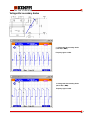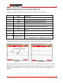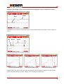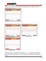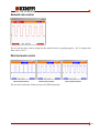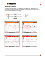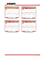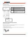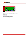
1
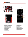
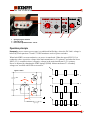
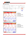
Service manual
Ver. 1.0
FEED
400
Contents
General…………………………………………………….3
Technical data………………………………...…………...3
Switches and connectors………………………….………4, 5
Operation principle……………………...………………..5
IGBT-module control………...…………………………. 6, 7
Voltage after secondary diodes…………..…………...... 8, 9
Troubleshooting/diagram…………………...…………...10-12
Wire feeder´s error codes……………………….……….12
Signals between power source and wire feeder………...13-15
Solenoid valve control…………………………….………16
Wire feed motor control.………………………….……...16
Torch connection……….………………...……………….17, 18
Signals from Wf-unit´s connectors…...………………….19
Cooling unit control……………….……………………...20
Adjusting the cooling unit pressure watch limit.…….....20
Power source control card A001 layout..…...…………..21
Wire feed unit control card A001 layout………………..21
MSD 1-meter unit layout..……………………...………...22
Notes……………………………………...………………..23
2
General
Kempomig-power sources are MIG/MAG and MMA –power sources designed for professional use.
Kempomig-power sources are inverter power sources based on IGBTs controlled by PWM principle.
The operating frequency is fixed on 18 kHz throughout the machine´s operating range.
Kempomig-power source together with Feed-unit form a compilation, in which the Feed-unit controls
all the operations. Feed-unit´s all functions are programmatically controlled.
Technical data
Supply voltage
Connection power
Supply cable/fuses
Loadability
3200
4000
3~ 50 / 60 Hz 400 V +10….-15 %
13,4 kVA / 320 A (50 % ED)
4 x 2,5 S / 16 A slow
320 A / 32,8 V (50 % ED)
250 A / 30,0 V (100% ED)
3~ 50 / 60 Hz 400 V +10….-15 %
18,4 kVA / 400 A (40 % ED)
4 x 2,5 S / 16 A slow
400 A / 36,0 V (40 % ED)
250 A / 30,0 V (100% ED)
Welding current adj. range
Welding voltage adj. range
10 A – 320 A (MMA)
10 V – 35 V (MIG)
10 A – 400 A (MMA)
10 V – 40 V (MIG)
Max. welding voltage
OCV
Idling power
Degree of protection
Measures
Length
Width
Height
40 V / 320 A (MMA)
approx. 75 V
< 55 W
IP 23C
40 V / 400 A (MMA)
approx. 75 V
< 55 W
IP 23C
940 mm
515 mm
880 mm
940 mm
515 mm
880 mm
3200W/4000W
Water tank volume
Cooling power
Max. pressure
Max. flow
3l
620 W
400 kPa
4 l / min.
FEED 400
Supply voltage
Loadability
Wf-speed
Wire spool (max)
Weight
Measures
30 Vac 50/60 Hz (150 VA)
60% ED
100% ED
400 A
310 A
0,5…18/25 m/min
20 kg (φ 300 mm)
15 kg
Length
Width
Height
570 mm
210 mm
440 mm
3
Switches and connectors
9
1
8
2
19
7
3
6
18
4
20
5
21
22
23
24
25
10
11
12
17
13
14
1
2
3
4
5
6
7
8
9
10
11
12
13
15
16
Process selection
Local / remote control selection
Wire feed speed-/ plate thickness display
Wire feed speed -/ power adjustment
Voltage -/arc length -/ current setting
Local / remote control
Voltage -/ current set value display
Dynamis adjustment, MIG/MAG
Synergic program number
On/off-signal lamp
Overheat signal lamp
Dynamics adjustment, MMA
Cooling method selection
14
15
16
17
18
19
20
21
22
23
24
25
MSD 1-meter unit
Coolant overheat signal lamp
Cooling unit test switch
Missing pressure signal lamp
Main switch S001
Welding current connection
Welding current connection
Control connection (amphenol 10-pin)
Control connection fuse 6,3 A, slow
Cooling unit fuse 2 A, slow
Coolant connector, pressure
Coolant connector, return
4
5 6 7
4
3
2
1
8
9
H
L
1
1
2
3
1
2
3
2
3
Synergic program selection
Crater fill on/off
Post current adjustment 40 ms…760 ms
Operation principle
Kempomig- power sources power stage is a traditional half-bridge, where the DC-link´s voltage is
halved by load capacitors C2 and C3. IGBT transistors work as power switches.
When both IGBTs are non-conductive, no power is transferred. When the upper IGBT (V2) is
conductive, there is positive voltage in the main transformer´s (T1) primary, and when the lower
IGBT (V3) is conductive there is negative voltage in the main transformer´s (T1) primary.
Power is adjusted by changing the IGBT timings (PWM). Main transformer T1 secondary
voltages are rectified with a full-waverectifier.
UG2
approx. + 570 V
V2
C2
UG3
U1
t
UG2
T1
U1
t
V3
C3
t
UG3
U2
U2
t
5
IGBT-module control
A
B
A
A = Gate pulse
(10 A / 20,4 V, MMA)
B = Voltage over the lower IGBT
(10 A / 20,4 V, MMA)
Inverter frequency approx. 17 kHz
B
A
A = Gate pulse
(100 A / 24,0 V, MMA)
B = Voltage over the lower IGBT
(100 A / 24,0 V, MMA)
Inverter frequency approx. 17 kHz
B
6
IGBT-module control
A
B
A
A = Gate pulse
(320 A / 32,8 V, MMA)
B = Voltage over the lower IGBT
(320 A / 32,8 V, MMA)
Inverter frequency approx. 17 kHz
B
A
A = Gate pulse
(400 A / 36,0 V, MMA)
B = Voltage over the lower IGBT
(400 A / 36,0 V, MMA)
Inverter frequency approx. 17 kHz
B
7
Voltage after secondary diodes
C
C
C = Voltage after the secondary diodes
(10 A / 20,4 V, MMA)
Frequency approx. 35 kHz
C
C = Voltage after the secondary diodes
(100 A / 24,0 V, MMA)
Frequency approx. 35 kHz
8
Voltage after secondary diodes
C
C
C = Voltage after secondary diodes
(320 A / 32,8 V, MMA)
Frequency approx. 35 kHz
C
C = Voltage after secondary diodes
(400 A / 36,0 V, MMA)
Frequency approx. 35 kHz
9
Troubleshooting
The device may be repaired only by a person legally authorized perform electric work!
Always check the device visually first, to find possible damages like loose wires, breaks or
signs of overheating.
.
Also note the condition of the welding cables, welding gun and wire feed mechanism.
Troubleshooting diagram
DISTURBANCE
The machine won´t start. WFunit´s displays remain blank.
The fuses blow during machine
startup.
The machine welds, but displays
remain blank.
Power source stays on MMA,
even though MIG is selected by
the panel.
POSSIBLE CAUSE
Net fuse has blown
REMEDY
Check the net fuses
Faulty supply cable
Check the supply cable
Faulty main switch
Check the main switch
Faulty aux. transformer
Check the aux. transformer
Faulty intermediate cable
Check the intermediate cable
between power source and wf-unit
A faulty primary side power
semiconductor
Check the primary rectifier and
IGBT-module condition
A faulty main circuit card
Check the load capacitors. See, if
there are marks of insulation
damages on the main circuit card.
A faulty aux. transformer
Check the aux. transformer
A faulty secondary unit
Check the secondary diodes
Faulty flat cable
Check flat cables & connectors
between control card A001 and
operating panel.
Faulty operating panel
Replace the operating panel
Faulty flat cables
Check flat cables & connectors
between control card A001 and
operating panel.
Faulty synergy card P002
Disconnect the flat cable from P002
synergy card. As a result of this, if
the power source goes to MIG, then
replace the P002.
10
DISTURBANCE
Error code E08 is shown on the
panel display
POSSIBLE CAUSE
Faulty welding gun
REMEDY
Check the welding gun condition
Faulty wf-unit control card
A001
Check the wf-unit´s zener diodes
V27 and V28 (24 V/5 W) on
control card A001. If these diodes
get damaged, there is an insulation
problem in the welding gun
between welding circuit and start
wires
The equipment welds ok on spray
arc values, but on short- and
globular-arc it is impossible to
weld
Faulty intermediate cable
Check the intermediate cable
between wf-unit and power source
and see that the process selection
works ok (I-line)
The power source doesn´t start
the cooling unit
Faulty intermediate cable
Check the intermediate cable
between wf-unit and power source
and see that the process selection
works ok (I-line)
Faulty power source control
card A001
Check the signals on control card
A001´s connector X7
Faulty power source control
A002
If the signals on control card A001
connector X7 are ok, then replace
the control card A002
The equipment welds poorly on
short- and globular arc
Power source´s control card
A001
See, if there is a resistor R188
mounted onto the control card
A001. If one is found, remove it.
The arc is intermitted and
overheat signal lamp is flashing
at the same time
DC-link overvoltage
Measure the supply voltage.
Overvoltage watch stops welding if
supply voltage rises above 520 Vac.
Wf-unit doesn´t control the
power source
Faulty intermediate cable
Check the rectifier unit VG102
wiring and if the unit is damaged,
the DC-link voltage may
momentarily rise above +900 V,
which activates the watch circuit.
Check the intermediate cable
between power source and wf-unit
Faulty aux. transformer
Check the auxiliary transformer and
make sure 18 Vac is taken to power
source´s control card connectors
X15/1 and X15/2
Faulty control card A001
Check wf-unit control card A001
11
DISTURBANCE
The power source can´t reach
maximum output
POSSIBLE CAUSE
Net fuse has blown
REMEDY
Check the net fuses
A faulty supply cable
Check the supply cable
A faulty main switch
Check the main switch
A faulty primary rectifier
Check the primary rectifier.
Measure the DC-link voltage during
idling and under load (530…570
Vdc)
A faulty control card A001
On the power source´s control card
A001, check that the IGBTmodule´s gate pulses are correct.
Replace the control card if
necessary.
A faulty control card A001
On the power source´s control card
A001, check that the set value is
developed correctly (H-line; 0-10
Vdc). Replace if necessary.
Wire feed unit error codes
E02
E08
Gun switch is being pressed, while MMA welding has been selected by the FEED
panel
Liquid cooled PMT-gun has overheated
E09
Wf-motor has been overloaded
E11
PMT-gun has been tried to use, though PMT-/RMT-functions have been disabled
by jumper 5
Shielding gas watch has interrupted welding (GG 400)
E12
12
Signals between power source and wire feeder unit
Signals in the control cable between the power source and the wire feeder unit:
Pin
Signal
Explanation
A
-
B
30 Vac
Supply voltage for wire feeder unit (fuse 6,3 A slow)
C
30 Vac
Supply voltage for wire feeder unit (fuse 6,3 A slow)
D
-
E
Power source size / Arc
on
F
0V
G
-
H
0 - 10 V
I
Process selection /
MIG/MAG-dynamics
-
Power source size detection / Arc on-info to the wf-unit
GND
Set value information to the power source (current or voltage)
+ 10 V = MMA
+ 0,5 – 3,5 V = MIG/MAG-process and MIG/MAG-dynamics setting
Voltages in the E-line of control cable between the power source and the wire feeder:
Power source size Arc on-info
Kempomig 3200
Kempomig 4000
During startup the wire feeder detects the power source size, based on the voltage level at E-line.
When the arc is ignited the power source pulls down the voltage in E-line, which gives an ar onsignal to the wire feeder. This arc on-signal can be used for different kinds of mechanization
purposes.
13
Voltages in the H-line of the control cable between the power source and the wire feeder:
Maksimi
Minimi
On MMA the wire feeder unit starts the power stage and develops an analog set value voltage of
0-10 V.
Start
Minimum
Maximum
Stop
Post-current time minimum = 40 ms
Post curren time medium = 340 ms
Post current time maximum = 760 ms
On MIG/MAG the wire feeder unit starts and stops the power stage accoding to the gun switch
and develops the analog set value voltage (0-10 V) and post current time.
14
Voltages in the I-line of the control cable between the power source and the wire feeder:
On MMA the voltage of I-line is approx. + 10 V
MIG/MAG dynamics - 9
MIG/MAG dynamics 0
MIG/MAG dynamics + 9
On MIG/MAG-process the voltage in I-line is approx. + 0,5 - 3,2 V, depending on the dynamics
setting. Note, that when welding with 1-MIG the dynamics setting is optimized according to the
filler material and gas-combination in use, so the adjustment range depends on the chosen 1-MIG
program.
15
Solenoid valve control
The wf-unit develops control voltage for the solenoid valve, by pulsing approx. + 40 V voltage with
Pulse ratio of 50 %.
Wire feed motor control
Wire feed speed minimum
Wire feed speed 10 m/min
Wire feed speed maximum
The wf-unit controls the feed motor speed by PWM-principle.
16
Welding gun connection
The voltage ”direction” changes every 20 ms in the gun control circuit. On the negative half
cycle the gun switch and temperature watch (PMT W) states are read. On the positive half cycle
the state of an RMT 10 guncontroller is read.
D
D
D
Gun connection open
D
Startti
Gun start (MT-type guns)
D
PMT-gun connected
PMT-gun start
17
D
D
PMT-connected and RMT in position 1
D
PMT-connected and RMT in position 3
D
PMT-connected and RMT in position 5
PMT –gun start and RMT in position 5
18
Signals from Wf-unit´s connectors
Remote controller connector XW101
Pin
Signal
Explanation
A
-
B
30 Vac
Supply voltage (fuse 6,3 A slow)
C
30 Vac
Supply voltage (fuse 6,3 A slow)
D
-
E
+ 10 V
F
0V
G
0 - 10 V
Wire feed speed set value
H
0 - 10 V
Set value to power source (current or voltage)
I
Process selection
-
Remote controller voltage reference
GND
+ 6 - 10 V = MMA
0 – 5 V or open = MIG/MAG-process
Motor gun connection XW101
Pin
Signal
Explanation
A
0V
B
+ 10 V
Motor gun adj. potentiometer voltage reference
C
0 - 10 V
Wire feed speed set value
D
+M
E
0 - 10 V
Voltage set value
F
Start 2
Start-switch connector 2
G
Start 1
Start-switch connector 1
H
-M
I
-
GND
Gun motor positive +
Gun motor negative -
19
Cooling unit control
The cooling unit is controlled on only on MIG process, while start is active. Cooling unit stops
the power stage if a missing coolnat pressure is detected or the coolant has overheated.
Connector Signal
X7/1
A001
X7/2
X7/3
X7/4
Cooling unit start (in start the power source control card A001
pulls down the voltage on connector X7/1)
Supply voltage to control card A002 electronics (+ 24 V)
GND
Stop, if coolant pressure is less than 1 bar or the coolant
temperature rises above + 60° C, then the control card A002
pulls down the voltage on connector X7/4, which shuts the
power source down.
A002
Adjusting the cooling unit pressure watch limit
(Kempomig 3200W/4000W)
If the missing coolant pressure signal lamp (17) is lit, though coolant circulates normally, then
The pressure watch limit can be adjusted as follows:
1. Run the pump by the test switch
2. Adjust the pressure switch adj. Screw counter-clockwise, until the warning lamp goes out.
3. Check the operation with a test weld
*
20
Power source control card A001 layout
X9
R75
X11
X14
X8
X16
X17
X18
X15
X10
R150
R39
R120
X6
X12
X1
X5
X13
X7
R152 R160
R39 Current max.
R75 Inv. frequency
R120 Voltage max.
R150 Voltage min.
R152 Current min.
R160 MMA ignition pulse
X16 Supply voltage selection,
460 V
X17 Supply voltage selection,
400 V
X18 MMA characteristic curve
for testing without a wire
feeder unit
X3
Wire feeder control card A001 layout
P17
R50 Post gas time 0…2 s. (A3.0)
R160 Crater fill angle
R50
P10
X9
X10
X7
R160
X10 Function
X1
X4
X8
X5
X12
X2
X12 EPROM-circuit 256k/512k selection
8
7
6
5
4
3
2
1
Closed
Open
PMT-/RMT-functions
Enabled
Disabled
Creep start
Pre gas
Wire feed max.
Off
Off
18 m/min
On
On
25 m/min
X3
X6
21
MSD 1-meter unit layout
X4
R3
R5
X1
X3
R6
R4
R3 Set current minimi (no function with Kempomig-power sources)
R4 Set current maximum (no function with Kempomig-power sources)
R5 Voltage display
R6 Current display
X3 (no function with Kempomig-power source)
X4 (no function with Kempomig-power sources)
22
Notes
23