1
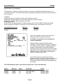
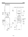
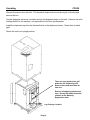
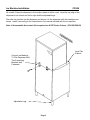
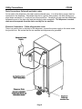
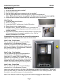
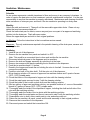
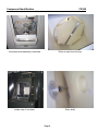
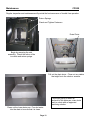
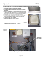
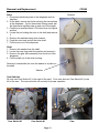
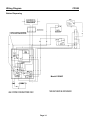
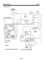
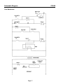
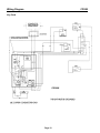
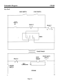
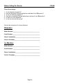
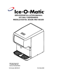
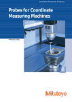
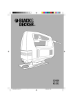
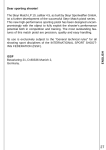
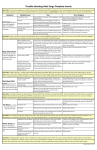
SERVICE/INSTALLATION MANUAL
HOTEL DISPENSER
MODEL-CD300
Ice-O-Matic
11100 East 45th Ave
Denver, Colorado 80239
Part Number 9081292-01
Print Date 1/09
Introduction
CD300
To the owner or user: This product manual is a source of information about the installation,
start up, cleaning, maintenance and repair of the product.
Table of Contents
Introduction
Page 1
Specification/Limitations
Page 2
Diagrams
Page 3
Uncrating
Page 4
Ice Machine Installation
Page 5
Utility Connections
Page 6
Initial Start Up and Use
Page 7
Sanitation and Maintenance
Page 8
Component Identification
Page 9
Maintenance
Page 10
Service Diagnosis
Page 11
Adjustments
Page 12
Removal and Replacement
Page 13
Wiring Diagram-Push Button
Page 14-15
Wiring Diagram-Coin Mechanism
Page 16-17
Wiring Diagram-Key Card
Page 18-19
Before Calling For Service Information
Page 20
Warranty Information
Page 2
Ice-O-Matic
11100 E. 45th Ave.
Denver, Co. 80239
800-423-3367
The CD300 Service Parts Manual is available separately, Part Number 9081293-01
Page 1
Specifications
CD300
Specifications and Limitations
This dispenser is designed to dispense cubed ice only and to be installed and operated indoors, in a
controlled enviroment. Its minimum and maximum operating temperature limits are the same as those for
the ice machine.
Limitations:
z Must meet the same limitations as the cuber installed on top of it.
z Must allow adaquate space for air flow when using and air cooled machine.
z Must allow space for utility connection at the back.
z Must have a drain.
z The CD300 is compatable with Ice-O-Matics cuber models ICE250, ICE400, ICE500 and ICE600.
z A thermostatic bin control kit is required on all ICE Series cubers. (Part Number 1051020-02)
Operating Requirements:
Air Temperature
Voltage
Minimum
50° F
104 VAC
Maximum
100° F
126 VAC
Check the nameplate, located on the back of the
dispenser cabinet for specific information.
Ice-O-Matic ice machines are not designed for
outdoor installations.
Machine requires voltage indicated on rating
nameplate. Failures caused by improper voltage are
not considered factory defects. Extended periods of
operation at temperatures exceeding limitations
constitutes misuse under the terms of the Ice-O-Matic
Manufacture’s Limited Warranty, resulting in a loss of
warranty coverage. Specifications and design are
subject to change without notice.
Ice-O-Matic assumes no liability of any kind for
products manufactured by Ice-O-Matic that have been
altered in any way, including the use of any parts
and/or other components not specifically approved by
Ice-O-Matic.
The CD300 dispenser has a 2 year Parts warranty and a 2 year Labor Warranty.
Model
CD300P
CD300C
CD300K
Electrical
115/60/1
115/60/1
115/60/1
Amps
2.2
2.2
2.2
Vend Type
Push Button
Coin (25¢ Only)
Key Card
Page 2
Finish
Stainless Steel
Stainless Steel
Stainless Steel
Diagrams
CD300
Page 3
Uncrating
CD300
Remove the carton from the skid. Cut the plastic straps that secure the leg kit to the skid and
remove the box.
Use the dispenser carton as a cushion and lay the dispenser down on its back. Remove the bolts
holding the skid to the machine, and separate the skid from the dispenser.
Install the dispenser legs into the threaded holes in the dispenser bottom. Screw them in hand
tight.
Return the unit to an upright position.
There are keys taped to the grill
below the ice dispensing area.
Remove them and save them for
later use.
Remove all shipping material and
tape. Record the model and serial
number on the Warranty
Registration form.
Leg Package Location
Page 4
Ice Machine Installation
CD300
All models: Place the dispenser in the location where it will be used. Level the top edge of the
dispenser front to back and left to right with the adjustable legs.
Place the ice machine on the dispenser and secure it to the dispenser with the hardware and
straps. Install it according to the instructions in the manual included with the ice machine.
Note: A thermostatic bin control kit is required on all ICE Series Cubers. (PN 1051020-02)
Level The
Cabinet
Connect Ice Machine
To The Dispenser With
The Connecting
Brackets and
Fasteners.
Leg Package Location
Adjustable Legs
Page 5
Utility Connections
CD300
Drain Connections -Follow all applicable codes.
As ice melts in the dispenser, the water must be drained away. It is critical that a proper drain be
connected to the dispenser. Remember that this is a gravity drain system, the drain tubing must
slope down a minimum of ¼ inch per foot of horizontal run. Usually an air gap must be established
between the end of the drain tube and the building’s drain receptacle. The dispenser’s vented
drain must be separate from the drain used by the ice machine.
Electrical Connections - Follow all applicable codes.
There is a junction box on the back of the dispenser, connect the power supply to the wires inside
the junction box. Be certain that the ice machine and dispenser are grounded.
Page 6
Initial Start Up and Use
CD300
Final Check List
1. Is the ice machine properly installed?
2. Is the dispenser level?
3. Has the water supply been connected to the ice machine?
4. Has the proper power been connected to the ice machine and dispenser?
Note: When electrical power is supplied to the dispenser the rotor will rotate slightly.
5. Have the drain line been connected are they separate from the ice machine?
Initial Start Up
1. Locate key and unlock the sink.
2. Remove the sink.
3. Locate the ON-OFF switch move it to the ON position.
4. Return the sink to its original position.
5. Simulate a vend. The rotor should move 1/6 (one sixth) of a
revolution on push button dispensers and a full revolution on coin
vending machines.
6. Record the ice machine model and serial number on the last page
of this manual and on the warranty registration form. Mail the
warranty information to Ice-O-Matic.
Operational Note: Every 6 hours the rotor will be activated to
agitate the ice. This may result in some ice in the chute.
How To Use – Push Button
The ice machine will start and run periodically to
maintain the ice in the dispenser’s hopper.
Push the “ICE” button to fill the clear plastic chute
with ice. Push down on the chute to release the ice
into a waiting container. Allow the chute to return all
the way up to its at rest position.
How To Use – Coin Vending
The ice machine will start and run periodically to
maintain the ice in the dispenser’s hopper.
Insert one U.S. quarter (25¢) or a special token,
available from Ice-O-Matic, PN TKNS. The unit will
fill the ice chute with ice, Push down on the chute to
release the ice into a waiting container. Allow the
chute to return all the way up to its at rest position.
How To Use – Room Card
The ice machine will start and run periodically to
maintain the ice in the dispenser’s hopper.
Insert room card into the slot in the front of the dispenser, and push the vend button. The unit will
fill the ice chute with ice, Push down on the chute to release the ice into a waiting container. Allow
the chute to return all the way up to its at rest position.
Note: If the chute is not all the way up, the unit cannot resupply the chute with ice.
Page 7
Sanitation / Maintenance
CD300
Schedule
An ice system represents a sizable investment of time and money in any company’s business. In
order to receive the best return on that investment, periodic maintenance is required. It is the user
responsibility to see that the machine is properly maintained. Maintenance and cleaning should be
done a minimum of twice per year, and more if the ice machine is operating is a dusty area.
Monthly:
Unlock the sink and remove it. Then pull out the removable upper drain chute. Clean out any
debris that may have accumulated in it.
Check the lower drain pan for debris, remove any and pour one quart of an approved sanitizing
solution into the drain pan. Flush with warm water.
Return the upper drain pan and sink to their original positions.
Ice Machine: Follow the instructions in the ice machine service manual.
Dispenser: The only maintenance required is the periodic cleaning of the drain pans, screens and
sanitizing the bin.
Sanitizing
1. Vend all ice out of the dispenser
2. Remove the ice machine front panel and switch it to OFF.
Note: This would be a convenient time to clean and sanitize the ice machine.
3. Disconnect electrical power to the dispenser and ice machine.
4. Remove the sink and hopper assembly by unlocking it at the base.
5. Remove two screws at the back connecting the ice machine to the dispenser.
6. Push the ice machine back 5 ½ inches.
7. Reach in the hopper and locate the nut holding the rotor to its shaft. Unscrew the nut and
remove the metal parts.
8. Push the rotor back off its drive shaft. Pull the rotor out of the dispenser.
9. Mix a cleaning solution of 8 ounces of approved ice machine cleaner and 3 quarts of warm
(95ºF-115ºF) potable water.
10. Scrub the interior of the dispenser’s hopper and rotor with the cleaning solution.
11. Scrub the metal parts removed in step 7 with the cleaning solution.
12. Scrub the inside of the ice with a clean cloth and the cleaning solution.
13. Mix two gallons of approved sanitizing solution; one possible solution is 1 ounce of household
bleach to 2 gallons of warm (95ºF-115ºF) potable water.
14. Thoroughly wash the inside of the dispenser’s hopper, including the shaft and all side of the
rotor with the sanitizing solution.
15. Thoroughly wash the inside of the ice chute with the sanitizing solution.
16. Thoroughly wash the metal parts and the nut removed in step 6 with the sanitizing solution.
17. Reassemble rotor to shaft, return metal parts to rotor and secure with nut.
18. Return the ice machine, all panel, covers and the sink assembly to their original positions.
19. Resecure the ice machine to the dispenser.
20. Reconnect power and switch the ice machine ON.
Page 8
Component Identification
CD300
View when sink assembly is removed.
Rotor as seen from the top.
Inside view of ice chute.
Rotor shaft.
Page 9
Maintenance
CD300
Regular inspection and maintenance will provide the best assurance of trouble free operation.
Return Springs
Check and Tighten Fasteners
Drain Chute
Begin by removing the sink
assembly. Check the action of the
ice chute and return springs.
Pull out the drain chute. Clean out any debris
that might be in the chute or screens.
Thoroughly spray or wash all
surfaces of the drain pan, drain chute
and ice chute with an approved
sanitizing solution.
Clean out the lower drain pan. Pour hot water
into the drain to be sure that it is clean.
Page 10
Service Diagnosis
CD300
Symptom
Probable Cause
Possible Correction
Does not dispense.
No power to dispenser.
Check for power.
Ice chute not all the way up.
Push ice chute up.
No ice in hopper.
Check ice machine, it may
be off or the dispenser’s
storage capacity may have
been exceeded.
Dispenser ON-Off switch is OFF.
Move switch to ON position.
Push button switch does not work.
Check switch, replace switch
if it will not close.
Coin switch does not work.
Check switch, replace switch
if it will not close.
Card switch does not work.
Check switch, replace switch
if it will not close.
Transformer failed.
Check-replace if open.
Safety switch open.
Check switch, replace switch
if it will not close.
Relay has failed.
Check-replace relay if coil or
contacts are open
Gear reducer motor is open or stuck.
Check motor, replace if open.
Drive shaft broken.
Check drive shaft, replace if
broken.
Gear reducer stripped internally.
Check if motor turns but output
shaft does not. Service or
replace gear reducer.
Does not stop vending.
Vend or cam switch stuck.
Check cam or vend switch.
Ice chute fills by itself.
Result of ice agitation.
This is normal.
Rotor not timed with cam switch.
Adjust cam switch.
Vend switch stuck.
Check vend switch.
Page 11
Adjustments
CD300
The gear motor cam must be properly adjusted to properly position the dispensing rotor.
1. Disconnect electrical power to the dispenser.
2. Locate the sink key, unlock sink and remove it from the
dispenser.
3. Observe the position of the rotor through the cube chute.
The rotor and cam switch must be in the positions shown.
If they are not, the position of the cam must be adjusted.
4. Rotate the rotor until it has blocked the opening.
5. Loosen the cam on the shaft and rotate it until the cam
switch follower drops into the lowest part of the cam.
6. Tighten the cam onto the shaft.
7. Return the sink to its original position.
Proper position of rotor at rest.
Cube chute
opening.
Microswitch
cam follower.
Correct positions of cam and rotor at rest.
Page 12
Removal and Replacement
CD300
Rotor
1. Disconnect electrical power to the dispenser and ice
machine.
2. At the back, remove two bolts securing the ice machine
to the dispenser. If a bin thermostat is being used, pull
the thermostat capillary tube up and out of the hopper.
3. Push the ice machine back 51/2 inched from its original
position.
4. Locate the nut holding the rotor to the shaft and remove
it.
5. Remove the stainless steel drive channel.
6. Push the rotor back and off the drive shaft.
7. Pull the rotor out of the dispenser.
Channel
Shaft
1. Remove the washer from the shaft.
2. Locate the snap ring under the washer and remove it.
3. Remove the gear drive assembly from the front of the
dispenser.
4. Pull the shaft out of the drive housing.
Reverse to reassemble, be sure the washer is in place on
the shaft.
Washer
Cam Switches
All units use Cam Switch #1 (to the right of the cam). Coin units also use Cam Switch #2 (to the
left of the cam. The cams must be set correctly for proper operation.
Cam Switch #2
Cam Switch #1
Page 13
Cam
Wiring Diagram
CD300
Button Dispensing
Model CD300P
Page 14
Schematic Diagram
CD300
Button Dispensing
Model CD300P
Page 15
Wiring Diagram
CD300
Coin Mechanism
CD300C
Page 16
Schematic Diagram
CD300
Coin Mechanism
CD300C
CD300C
Page 17
Wiring Diagram
CD300
Key Card
CD300K
Page 18
Schematic Diagram
CD300
Key Card
CD300CCD300K
Page 19
Before Calling For Service
CD300
Check these things.
1.
2.
3.
4.
5.
6.
Is the dispenser plugged in?
Has the dispenser’s internal switch been switched to the ON position?
Is the ice machine plugged in?
Has the ice machine’s internal switch been switched to the ON position?
Is there ice in the dispenser?
Is the ice chute all the way up?
Record this information for future reference.
Dispenser
Model Number:_______________________________________
Serial Number: _______________________________________
Date of Installation:____________________________________
Service Company:_____________________________________
Ice Machine
Model Number:_______________________________________
Serial Number: _______________________________________
Date of Installation:____________________________________
Service Company:_____________________________________
Page 20