1
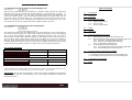
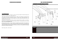
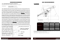
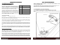
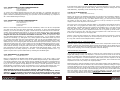
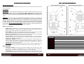
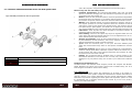
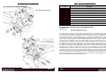
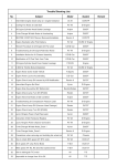
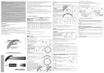
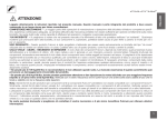
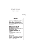
Marin Attack Trail FRS160
Service Manual
Edition 1: January 2011
2011 Marin Attack Trail Service Manual
9.0: NOTES
Page 19
2011 Marin Attack Trail Service Manual
7.1: Removing the rear Dropouts from the Swinging Arm.
Tools Required:
Table of Contents
5mm Allen Key
6mm Allen Key
Both Left (4) and Right Hand (2) dropouts are a modular design, that can be replaced if
damaged. They are each attached to the Swinging Arm (3) by two bolts (1a & 1b) . To
remove either Right Hand (2) or Left Hand (4) dropout apply heat to the assembly - to
reduce the Loctite strength - then using the 5mm Allen key for the outside bolts (1a) and
6mm Allen key for the Inside Bolts (1b), undo both bolts and remove them from the assembly. The Dropout (2 & 4) should now be detached from the Swinging Arm (3). Take
care not to loose any of the components & also handle hot parts with care.
1.0
Introduction
2.0
Geometry
3.0
Preparations for riding:
3.1
3.2
3.3
7.2: Assembling the Dropouts onto the Swinging Arm
Tools Required:
5mm Allen Key
6mm Allen Key
Torque Wrench
Loctitie 638 retaining compound
It is important to make sure the Swinging Arm (3) and Dropouts (2 & 4) are clean and free
from mud, grease and other dirt, which could prevent the Dropouts (2 & 4) and Swinging
Arm (3) from fitting together perfectly. Before assembling the bolts (1a & 1b), apply a
small amount of Loctite 638 retaining compound to the threads of each of the bolts (1a &
1b), as well as to the outside of the Female Chain Ring Bolts (1b) so an even covering is
achieved. Next, assemble the parts as shown in Fig 7. making sure the Bolts (1a & 1b) are
correctly positioned as shown. Using the Torque Wrench, tighten the bolts (1a & 1b) to the
correct torque as specified in Section 8.0. Wipe off any excess retaining compound.
4.0
Safety
5.0
Lubrication
6.0
Servicing the Rear Suspension:
6.1
6.2
6.3
8.0: TORQUE SETTINGS
Quad-Link 2 Suspension:
M8 AeroSpace Nuts
Bearing Caps
Nm
lbs.ft
18.0 +/- 1.8
13.3 +/- 1.4
5.0 +/- 0.5
3.7 +/- 0.4
7.0
15.0 (Min) / 25.0 (Max)
11.0 (Min) / 18.5 (Max)
Torque explained: If no suitable Torque Wrench is available a Torque of 5 lbf.ft can be obtained by applying a force of 5lb, with a Spring Balance, to the end of a spanner, 1 Foot in length.
IMPORTANT: For all other torque settings, refer to the specific manufacturers information
bundled with this manual, or alternatively, refer to the specific manufacturers website for
further information.
Page 18
Removing the Rear Shock and Swinging Arm
Stripping and Re-assembling Front and Rear Quad-Links
6.2.1 Extraction of flanged KP5AX Bearings
6.2.2 Insertion of flanged KP5AX Bearings
6.2.3 Re-Assembly of Quad-Links
Re-assembling the Rear Suspension
6.3.1 Correct Orientation of Front and Rear Quad-Links
6.3.2 Re-Assembling the Rear Suspension
Servicing The Marin Rear Dropout System
7.1: Removing the Rear Dropouts from the Swinging Arm.
7.2: Assembling the Rear Dropouts onto the Swinging Arm
8.0
Tightening Torque Settings
9.0
Notes
Rear Dropout Assembly
Bolts
Making Adjustments
Set up of Fork
Set up of Rear Shock
2011 Marin Attack Trail Service Manual
2011 Marin Attack Trail Service Manual
7.0: SERVICING THE MARIN DROPOUT SYSTEM.
Fig.7: Exploded view of Dropout Assembly
1.0: INTRODUCTION
Thanks for choosing Marin. We hope you will enjoy all the benefits its advanced design and
engineering will bring to your riding experience.
This manual will guide you through the set-up, safety and maintenance procedures that
are specific to your Marin suspension frameset. For other more general information, we
strongly advise that you also read thoroughly the General Instruction Manual that is also
supplied with your new bike.
Also, please note that the specification of all the components that are fitted to your bike as
standard may be obtained from the Marin Bikes Brochure or alternatively from the Marin
Bikes website www.marin.co.uk
Bundled with this manual, are the respective manufacturers instructions and manuals for
the branded parts that go to make up the Marin build. Please take time to study both this
manual and all the relevant instruction manuals to ensure you have a continually safe and
well set-up bike before every ride, and to help you build up a relationship of knowledge
between you and your Marin Dealer.
Item
Marin design team. January 2011
Page 4
Description
1a
Chain ring Bolt; Male
1b
Chain Ring Bolt; Female
2
Dropout, Maxle Modular type, Derailleur side
3
Swinging Arm Boss
4
Dropout, Maxle Modular type, Disc side
Page 17
2011 Marin Attack Trail Service Manual
2011 Marin Attack Trail Service Manual
6.3.2: REASSEMBLING THE REAR SUSPENSION
2.0: GEOMETRY
(For pictorial views of the assembly, refer to Fig. 2 on page 10)
Tools Required:
Medium Flat Bladed Screwdriver
10mm A/F Spanner
Torque Wrench with 10 A/F socket
The re-assembly of the rear suspension is basically the reverse of the dis-assembly procedure. Starting with the shorter rear Quad Link (5) ensure the rear Quad-Link (5) is complete and correctly assembled (See Fig.3). Next make sure the rear Quad-Link (5) is correctly orientated (see fig. 5) and pass a 90mm M8 Shaft (9) through the rear Quad-Link
(5) and Main Frame (6). Next take the rear shock (7) and assemble the front mount of the
rear shock (7) using SKF LG/AF or Castrol Optimol T anti fret paste on the contacting surfaces, into the forward shock mount of the Mainframe (6). IMPORTANT. Ensure the rear
shock is the correct way up, with the blue Pro Pedal lever facing upwards. Assemble the
longer front Quad-Link (4) onto the Mainframe (6), and pass a 90mm M8 Shaft (9) through
the front Quad-Link (4), the Mainframe (6) and through the front of the shock (7) until the
M8 Shaft (9) is showing out the other side of the front Quad-Link(4). You should now have
both front and rear Quad-Links assembled onto the Mainframe (6), with the rear shock (7)
in position. Next lower the Swinging Arm (3) onto the rear suspension assembly and position the Swinging Arm (3) onto the front Quad-Link (4) first. Pass a 90mm M8 Shaft (9)
through the front Quad-Link and Swinging Arm (3) until it has passed though the other
side. Next rotate the Swinging Arm (3) down to attach it to the rear Quad-Link (5) and the
rear of the shock (7). Once you have the Swinging Arm (3) in the correct position, make
sure that the rear Quad-Link (5), the Swinging Arm (3) and the rear shock (7) though
holes are all concentric with each other, and push through the 100mm M8 Shaft (8). Next
re-fit the M8 AeroSpace Nuts (3). IMPORTANT: before final tightening of the M8 AeroSpace
Nuts (3), it is important to make sure that there is a balanced amounts of thread showing
through the M8 AeroSpace Nuts (2) on each side of the front and rear Quad-Link assemblies. Using the screwdriver in the end of the M8 Shafts (8 & 9), and the 10mm spanner,
adjust all 4 M8 Shafts (8) accordingly. Refer to Fig. 6. Tighten all M8 AeroSpace Nuts (2) to
the recommended settings. (Refer
to the Tightening torque settings
Fig.6: Maximum Thread Protrusion
in Section 8.0) Next make sure
that there is still a substantial
amount of Molykote 111 Silicon
covering all the KP5AX flanged
bearings. Refit the Bearing Caps
(1) by screwing them into the
links. Take care not to cross
thread the Bearing Caps (1). Using the screwdriver, tighten the
Bearing Caps (1) to stop them
from shaking loose. (Refer to the
Tightening torque settings in Section 8.0). Finally, refit the rear
wheel into the swinging arm.
Page 16
Fig.1: Geometry
FRAME SIZE
Head Angle (A)
Small / 16.5”
Medium / 17.5”
65°
65°
Large / 19”
65°
Seat Angle (B)
72°
72.5°
73°
Top Tube* (C)
577mm/22.7”
595mm/23.4”
606mm/47.3”
BB Height** (D)
337mm/13.3”
340mm/13.4”
341mm/13.4”
Stand Over (E)
792mm/31.2”
820mm/32.3”
836mm/32.9”
Wheel Base (F)
1111mm/43.7”
1133mm/44.6”
1146mm/45.1”
115mm/4.53”
120mm/4.72”
125mm/4.92”
Seat Post (H)
30.9 mm/1.217”
30.9 mm/1.217”
30.9 mm/1.217”
Seat Tube (I)
419.1mm/16.5”
444.5mm/17.5”
482.6mm/19”
Head Tube (G)
Note: This is ‘Showroom’ Geometry, ie: without a rider sat on the bicycle.
*Top tube length is the distance from the point where the centre line of the head tube meets the centre line of the top
tube, horizontally back to the centre line of the seat tube.
**BB Height will vary, depending on what tyre size is actually fitted.
Page 5
2011 Marin Attack Trail Service Manual
2011 Marin Attack Trail Service Manual
3.0: PREPARATIONS FOR RIDING
LGAF 3 compound Castrol Optimol T to the link contact surfaces on the Main
Frame and Swinging Arm.
3.1: MAKING ADJUSTMENTS:
Please refer to the specific component manufacturers
manual or published technical information about adjusting the components on your Marin.Instructions
may be downloaded from the relevant manufacturer’s
internet site, as shown in the table to the right.
Fulcrum
www.fulcrumwheels.com
Fox
www.foxracingshox.com
Kenda
www.kendauk.com
Mavic
www.mavic.com
If you are uncertain in any way, about making adjustments to any components on you Marin, then DO
NOT RIDE YOUR BIKE. Contact your Marin dealer who
will be able to advise you on how to go about setting
up you Marin for riding, and or making adjustments
to the components fitted to your Marin.
Maxxis
www.maxxis.com
Shimano
www.shimano.com
SRAM
www.sram.com
WTB
www.wtb.com
Loctite 638 & SKF LGAF3 can be purchased from Brammer Ltd www.brammer.co.uk
Castrol Optimol T can be purchased from Motobins www.motobins.co.uk
Molycote 111 can be purchased from Sil-Mid Ltd www.silmid.com
6.3: REASSEMBLING THE REAR SUSPENSION.
6.3.1: CORRECT ORIENTATION OF FRONT AND REAR QUAD-LINKS.
Note that both of the links MUST be orientated as shown, otherwise they will touch the rear
shock.
Fig.5: Quad-Link Orientation
Front Link (4)
3.2: SET UP OF FORK
Tools Required:
Good Quality Shock Pump.
Please note that for the detailed instructions for servicing and all matters relating to the
fork, please refer to the manufacturers instructions.
The front fork is pre-set with a standard setting when you buy your Marin. Before riding,
you will need to adjust the sag setting on the fork. This is to ensure it is set-up correctly
for your own body weight, so the fork will perform as intended.
Through hole is offset away
from down-tube on front
triangle (6)
To set sag on a front fork, you need to measure the amount the fork compresses when you
sit on the bike in the normal riding position. We recommend for the best synergy between
front and rear suspension systems to run approximately 32mm (20%) Sag on the front
fork.
Sag on forks is controlled by adjusting the Air Spring pressure, or if you have a coil spring
fork, the rate of the coil spring inside the fork. This is not adjustable, and requires the fork
to be rebuilt with a different spring. Please consult your Marin Dealer for more information.
Rear Link (5)
Rebound Damping adjustment:
This adjustment fine-tunes the speed at which the wheel returns to its normal ride height
after hitting a bump. To demonstrate the effect of this function, turn the adjuster to its
slowest setting. Press down on the handlebars to compress the forks, then release the
load. The suspension recovers very slowly to its original position.
Repeat the above with the adjuster turned to the fastest setting and the difference will be
seen immediately the load is released. We recommend the optimum setting is to adjust the
re-bound damping to be as slow as possible, but not so slow that the normal ride height is
not recovered. On very rough terrain, if the front or rear of the bike becomes progressively
lower as more bumps are hit then the re-bound damping is set too slow. On the other hand
Page 6
Page 15
2011 Marin Attack Trail Service Manual
2011 Marin Attack Trail Service Manual
if the bike feels choppy and not plush then the re-bound damping is too fast. A bit of trial
and error is needed to get the exact setting. Riders may choose to change their settings,
while stationary, depending on the terrain they are riding.
6.2.1: EXTRACTION OF KP5AX FLANGED BEARINGS
Tools required:
KP5AX bearing press tool.
6mm AF Allen Key
10mm AF Spanner.
To remove the KP5AX flanged bearings from the Link Body (4). Assemble the parts as
shown in Fig 10a. Using the 6mm Allen Key and 10mm spanner, tighten the assembly together until the KP5AX flanged bearing (5) is pressed out of the Link Body (4). Repeat on
all 7 other KP5AX flanged bearings.
6.2.2: INSERTION OF KP5AX FLANGED BEARINGS
Tools required:
Whyte KP5AX bearing press tool.
6mm AF Allen Key
10mm AF Spanner
Loctite 638
Before re-assembling both front and rear link assemblies, make sure all the components
are clean from dirt and have been thoroughly de-greased. To press the KP5AX flanged
bearings (5) into the Link Body (4) apply a small amount of Loctite 638 to the outside diameter of the KP5AX flanged bearing (5) and to the inside bearing bore of the Link Body
(4). Next assembly the components as illustrated in Fig.10b, noting how the bearing’s
flanged side must face towards the middle of the link. It is very important to make
sure the KP5AX flanged bearing (5) and Bearing Insertion tool 1 (3) are squarely seated
against the Link Body (4). With great care, slowly tighten the M8 Socket head cap screw
(7) with the 6mm Allen key and 10mm Spanner until you can see the KP5AX bearing (5)
being pressed squarely into the Link Body (4). Once the KP5AX flanged bearing is fully
seated and you can no longer tighten the M8 Socket Head Cap Screw further, undo the nut
and bolt and wipe away any excess Loctite from around the KP5AX flanged bearing, especially from the threads of the link. Repeat for the remaining 7 KP5AX Bearings. Finally,
check that the bearings are aligned with each other by inserting an M8 Shaft through each
pair of bearings at each ends of the link. The shaft must pass through freely. If not, then
the bearings are not sitting squarely in the links. Use the Bearing Insertion tool 1 (3)
again to square them up and confirm that by inserting the M8 Shaft again.
6.2.3: REASSEMBLY OF QUAD-LINKS
Tools required:
Molykote Silicon 111
Before re-assembling the Middle Shield Washer Components (3 see Fig.9), apply a good
quantity of Molykote 111 Silicon on top of the KP5AX flanged bearings. The Molykote Silicon should completely cover each bearing and be applied on both sides of each bearing as
it is assembled into the Link Body. Next assemble the Shield Washer Components (3 see
Fig.9), If you have applied enough Molykote 111 Silicon, it should spread from under the
Shield Washer component as they are positioned, so as to protect the bearing from contamination. Wipe this excess Silicon away from around the Shield Washer Components.
APPLICATION OF SKF LG/AF or Castrol Optimol T ANTI-FRET PASTE
Once the Links have been assembled correctly, SKF LGAF 3 Compound or Castrol
Optimol T must be applied to all outside faces of the bearing flanges, that contact
the Main Frame and Swinging Arm. It is additionally recommended to apply SKF
Page 14
3.3: SET UP OF REAR SHOCK
Tools Required:
Good Quality Shock Pump.
Please note that for the detailed instructions for servicing and all matters relating to the
rear shock, please refer to the manufacturers instructions. The rear shock is pre-set with
standard settings when you buy your Marin. Before riding, you will need to fine adjust the
sag setting on the rear shock. This is to ensure it is set-up correctly for your own body
weight, so the shock will perform as intended.
The correct ‘sag’ can be found using the sliding ‘o’ ring fitted to the shaft of the shock piston. Slide the ‘o’ ring against the shock body. Then gently sit on the bike in your normal
riding position. Carefully dismount and measure the distance the ‘o’ ring has moved away
from the shock body. The optimum distance for the Marin QUAD 2 system is between
12mm (25%) and 15mm (30%) displacement from the ‘o’ ring back up to the shock body.
25% sag gives a firmer ride, and 30% sag gives a plusher ride. Trial and error is required
to arrive at a setting which you are happy with.
If there is less sag than required, fit a shock pump and release air pressure. Conversely if
there is greater sag than required, fit the shock pump and increase air pressure. Repeat
the ‘sag’ test until the desired displacement is achieved.
Rear Suspension Set-up - Rebound Damping:
When the shock is being compressed, this is known as the compression stroke. As the suspension recovers from compression back towards its full length, this is called the re-bound
stroke. All the shocks fitted as standard to the Marin full suspension bikes have factory set
compression damping, and manually adjustable rebound damping.
Rebound Damping Adjustment:
This adjustment fine-tunes the speed at which the rear wheel returns to its normal ride
height after hitting a bump. The adjuster is coloured red and is found on the rear shock .
An arrow marked slower indicates the direction to turn the dial to slow down the re-bound
speed of the suspension. To demonstrate the effect of this, turn the adjuster to its slowest
setting. Press down on the saddle to compress the suspension, then release the load. The
suspension recovers very slowly to its original position.
Repeat the above with the adjuster turned to the fastest setting and the difference will be
seen immediately the load is released. We recommend the optimum setting is to adjust the
re-bound damping to be as slow as possible, but not so slow that the normal ride height is
not recovered. On very rough terrain, if the rear of the bike becomes progressively lower
as more bumps are hit then the re-bound damping is set too slow. On the other hand if the
bike feels choppy and not plush then the re-bound damping is too fast. A bit of trial and
error is needed to get the exact setting. IMPORTANT SAFETY NOTE: Always stop riding
when making adjustments of any kind to the bicycle!
Page 7
2011 Marin Attack Trail Service Manual
2011 Marin Attack Trail Service Manual
Rear Shock Adjustment.
Fig.4a: KP5AX Bearing Extraction
Fig.4b: KP5AX Bearing Insertion
Please refer to the relevant Instruction Manual to learn more about the advanced features
of your rear shock.
4.0: SAFETY
IMPORTANT: The following are intended to be advisory notes on the safe use of your
Marin. If at any stage you are uncertain about the safety or safe operation of the bike as a
whole, or any specific component, then DO NOT RIDE YOUR Marin and instead please
consult the specific component manufacturers instruction manual or your Marin Dealer for
advice.
WARNING: As is the case with all mechanical components, the bicycle is subjected to
wear and high stresses. Different materials and components may react to wear and stress
fatigue in different ways. If the design life of a component has been exceeded, it may fail
suddenly causing possible injury to the rider. Any form of crack, scratches and decolouring
in highly stresses areas are showing that the component has exhausted its life time and
has to be replaced. If you are in any doubt about the condition of any of the components
on your Marin. DO NOT RIDE YOUR BIKE. Consult the specific component manufacturers
literature, or take your bike to your local Marin Dealer for advise.
Before your first ride:
•
•
•
•
•
•
Brake levers: Familiarise yourself with which brake lever operates which brake. As
standard the Marin is set-up so as the right-hand brake lever operates the front
brake, and the left hand brake lever operates the rear brake.
Gear Shifters: Familiarise yourself with the function and operation of the gear shift
levers in accordance with the manufacturers instruction and guidance
Marin Lock On Grips: Make sure the grips are securely fastened to the handlebars
and cannot rotate or become loose at any time during riding.
Tyre pressures: They should be set by your dealer before you collect the bike.
However, ensure that the tyre pressures are between the upper and lower limits as
shown on the sidewalls of the tyres.
Suspension Settings: Ensure that you have followed the recommended procedures for setting up the Marin suspension systems outlined in Sections 3.2 and 3.3
of this manual. Also refer to the relevant instructions and guidance as outlined in
the front fork and rear shock manuals.
IMPORTANT: please note that you must ensure that your Marin complies with your
countries National Legal Requirements when the bicycle is used on public roads.
After Every Ride:
•
Post-Ride cleaning: We strongly recommend cleaning your bike after every ride.
This provides you with the best opportunity of a close and systematic inspection of
almost every component, for damage and wear on a ride by ride basis.
•
Lubrication: Directly after cleaning your bike after a ride, is the best time to carry
out the lubrication regime for the various components as outlined in this manual,
Page 8
Item:
Description.
1
M8 Nut
2
M8 Washer
3
KP5AX Tool 1
4
Link Body
5
KP5AX Flanged Bearing
6
KP5AX Tool 2
7
M8x50mm Socket Head Cap Screw
Page 13
2011 Marin Attack Trail Service Manual
2011 Marin Attack Trail Service Manual
and in the respective component manufactures technical information.
6.2: STRIPPING AND REASSEMBLING FRONT AND REAR QUAD-LINKS.
Before every ride: Pre-ride safety check.
•
Frameset Components: We recommend that before every ride you visually inspect the mainframe swinging arm and associated components for signs of damage
or excessive wear due to hard use.
•
Brakes: Check the Disc and Brake pads for wear and performance degradation, and
the hydraulic hoses for damage, in accordance with the specific recommendations in
the relevant component makers instruction manual bundled with this manual.
•
Wheels: Check that both wheels are securely attached to the bike, and the respective dropout systems are correctly adjusted. Check the condition of both wheels,
and look for cracks or large dents in the aluminium Rim, and check for loose or broken spokes and/or spoke nipples, and wheels out of alignment in line with the specific recommendations in the relevant instruction manual bundled with this manual.
•
Lubrication: Check all parts have been lubricated in accordance with the specific
component makers instruction manual.
•
Gear Shifting: Check for and replace any frayed or degraded cable inner wire and
outer casing and check all relevant parts are in correct adjustment for use in accordance with the specific instruction manual
•
Steering and Headset: Check for loose headset bearings or tight spots when turning the handlebars in both directions, and service, adjust or replace in accordance
with the manufacturers specific instruction manual.
•
Tyres: Check for excessively worn, or cut tyres. Check the inflation pressure is
within the recommended range. Refer to the specific manufacturers recommendations.
•
Suspension Settings: Ensure that you have followed the recommended procedures for setting up the Marin suspension systems outlined in Sections 3.2 and 3.3
of this manual. Also refer to the relevant instructions and guidance as outlined in
the front fork and rear shock manuals.
•
Helmet: We recommend that for off-Road riding, a helmet meeting a reputable
international standard is used and be worn on every ride. Check the helmet is not
damaged in any way before riding. Do not ride if your helmet has sustained damage.
Fig.3: Assembly for both front and rear Quad-Links
Item
Description
1
KP5AX flanged bearing
2
Front or Rear Link Body
Designed for the following use:
The Marin Attack Trail bike has been designed, tested and complies with BS EN 14766
Safety Standard, for typical cross country and free-ride mountain biking use. It has not
been designed or tested for extreme down-hilling.
5.0: LUBRICATION
For the correct lubrication regime and maintenance of all parts on all models of Marin
bikes, please refer to the specific component manufacturers detailed instructions bundled
with this manual or for further information visit the specific manufacturers website. Any
lubrication requirements regarding the Marin Quad-Link suspension system are covered in
the disassembly and re-assembly sections in this manual. If you are in any doubt, please
contact your local Marin Dealer.
Page 12
Page 9
2011 Marin Attack Trail Service Manual
2011 Marin Attack Trail Service Manual
6.0: SERVICING THE REAR SUSPENSION
Item
Description
1
Link Cap Cover
2
M8 Aerospace Nut
3
Rear Swinging Arm
4
Front Link Assembly
5
Rear Link Assembly
6
Front Triangle
7
Rear Shock
8
M8 x 100mm long Stud
9
M8 x 90mm long Stud
Fig.2: Marin Rear Suspension
6.1: REMOVING THE REAR SHOCK AND SWINGING ARM
See Figure 2
Tools Required:
Medium Flat Bladed Screwdriver
10mm A/F Socket Wrench (2 off)
To remove the rear shock from the frame, first remove the rear wheel from the swinging
arm. Using the screwdriver, unscrew the 8 Bearing Caps (1) 4 per link. Next using the
10mm Sockets, undo the M8 Aerospace nuts (2) on the M8 shaft (8) that passes through
the rear link assembly (5) and swinging arm (3). Whichever Aerospace Nut (3) becomes
undone first, remove it, and pull the M8 Shaft (8) out from the other side. The swinging
arm (3) can now be rotated out of the rear link assembly (5). Next using the 10mm sockets undo the M8 Aerospace nuts (2) on the M8 Shaft (9) that pass through the front of the
Swinging Arm (3). Whichever Aerospace Nut (2) becomes undone first, remove it, and pull
the M8 Shaft (9) out from the other side. You can now lift off the Swinging Arm (3) from
the front (4) and rear (5) link assemblies. To remove the links from the main frame (6)
using the 10mm Sockets, undo the M8 Aerospace nuts (2) on the M8 shaft (9) that passes
through the Main Frame (6) and front of the rear shock assembly (7). Again whichever
Aerospace Nut (2) becomes undone first, remove it, and pull the M8 Shaft (9) out from the
other side. You can now remove the rear shock assembly (7) and Front Link Assembly (4)
from the main frame (6). To Remove the Rear Link Assembly (5) from the bike, using the
10mm Sockets, undo the M8 Aerospace nuts (2) on the M8 shaft (9) that passes through
the Rear Link Assembly (5) and the Main Frame (6) and remove the M8 shaft (9) and the
Rear Link Assembly (5) from the Main Frame (6).
Page 10
Page 11