1
2558A
AC Voltage Current Standard
IM 2558A-01EN
1st Edition
Product Registration
Thank you for purchasing YOKOGAWA products.
YOKOGAWA provides registered users with a variety of information and
services.
Please allow us to serve you best by completing the product registration
form accessible from our homepage.
http://tmi.yokogawa.com/
PIM106-11
Thank you for purchasing the 2558A AC Voltage Current Standard.
The 2558A is a stable signal generator that produces the following voltage and current signals.
• AC voltage: 1 mV to 1200 V; frequency: 40 Hz to 1000 Hz
• AC current: 1 mA to 60 A; frequency: 40 Hz to 1000 Hz
This user’s manual explains the features, operating procedures, and handling precautions of the
2558A. To ensure correct use, please read this manual thoroughly before beginning operation. Keep
this manual in a safe place for quick reference in the event that a question arises.
Notes
• The contents of this manual are subject to change without prior notice as a result of continuing
improvements to the instrument’s performance and functionality. The figures given in this manual
may differ from those that actually appear on your screen.
• Every effort has been made in the preparation of this manual to ensure the accuracy of its
contents. However, should you have any questions or find any errors, please contact your nearest
YOKOGAWA dealer.
• Copying or reproducing all or any part of the contents of this manual without the permission of
YOKOGAWA is strictly prohibited.
• The TCP/IP software of this product and the documents concerning it have been developed/created
by YOKOGAWA based on the BSD Networking Software, Release 1 that has been licensed from
the Regents of the University of California.
High voltage
The 2558A generates sinusoidal of up to 1440 Vrms.
• To prevent electric shock, be sure to read this manual before use.
• Improper operation may lead to serious, life-threatening accidents. Keep this manual
close to the 2558A so that the operator can refer to it anytime.
Trademarks
• Microsoft, Internet Explorer, MS-DOS, Windows, Windows NT, Windows XP, Windows Vista and
Windows 7 are either registered trademarks or trademarks of Microsoft Corporation in the United
States and/or other countries.
• Adobe and Acrobat are either registered trademarks or trademarks of Adobe Systems Incorporated.
• In this manual, the TM and ® symbols do not accompany their respective®registered trademark or
trademark names.
• Other company and product names are registered trademarks or trademarks of their respective
holders.
Revisions
May 2013 1st Edition
1st Edition: May 2013 (YMI)
All Rights Reserved, Copyright © 2013 Yokogawa Meters & Instruments Corporation
IM 2558A-01EN
Checking the Contents of the Package
Unpack the box and check the contents before operating the instrument. If the wrong items have been
delivered, if items are missing, or if there is a problem with the appearance of the items, contact your
nearest YOKOGAWA dealer.
2558A
Check that the product that you received is what you ordered by referring to the model name and suffix
code given on the name plate on the side panel.
MODEL and SUFFIX Codes
Model
2558A
Power cord*
Suffix Code
-D
-F
-R
-Q
-H
-N
Additional specifications
(options)
/C1
Specifications
1200 V, 60 A
UL/CSA standard power cord, maximum rated voltage: 125 V
VDE standard power cord, maximum rating: 250 V
AS standard power cord, maximum rating: 250 V
BS standard power cord, maximum rating: 250 V
GB standard power cord, maximum rating: 250 V
NBR standard power cord, maximum rating: 250 V
GP-IB interface
* Make sure that the attached power cord meets the designated standards of the country and area
that you are using it in.
No. (Instrument number)
When contacting the dealer from which you purchased the instrument, please give them the instrument
number.
Standard Accessories
The instrument is shipped with the following accessories. Make sure that all accessories are present
and undamaged.
Power cord (one cord that matches the suffix code is included)*
UL/CSA Standard
A1006WD
D
Measurement lead
set 758933
VDE Standard
A1009WD
BS Standard
A1054WD
F
Measurement lead
set B8506WA
AS Standard
A1024WD
Q
Alligator clip
adapter set 758929
R
GB Standard
A1064WD
H
NBR Standard
A1088WD
N
Rubber leg cap User’s manual
A9088ZM
* Make sure that the attached power cord meets the designated standards of the country and area
that you are using it in.
ii
IM 2558A-01EN
Checking the Contents of the Package
Optional Accessories (Sold separately)
The following optional accessories are available for purchase separately.
For information about ordering accessories, contact your nearest YOKOGAWA dealer.
Item
Measurement lead set
Measurement lead set
Measurement lead set
Alligator clip adapter set
Model/Part No.
758933
B8506WA
758917
758922
Min. Q’ty
1 set
1 set
1 set
1 set
Alligator clip adapter set
758929
1 set
High voltage alligator clip
B8099RC
B8099RD
Fork terminal adapter set
758921
Conversion adapter
758924
Safety BNC cable
701902
Safety BNC cable
701903
Safety terminal adapter set 758923
Safety terminal adapter set 758931
IM 2558A-01EN
1
1
1 set
1
1
1
1 set
1 set
Note
Safety terminal cable. Length: 1 m. Rating: 1000V
Current output cable. Length: 1.5 m.
Safety terminal cable. Length: 0.75 m.
Safety terminal-to-alligator clip adapter. Red and
black, 1 pc each. Rating: 300 V.
Safety terminal-to-alligator clip adapter. Red and
black, 1 pc each. Rating: 1000V.
Black. Rating: 5000 V
Red. Rating: 5000 V
Safety terminal-to-fork terminal adapter
BNC-to-binding post adapter.
BNC-BNC. Length: 1 m.
BNC-BNC. Length: 2m.
Spring clamp type. Red and black, 1 pc. each.
Screw-in type. Red and black, 1 pc. each.
iii
Safety Precautions
This instrument is an IEC safety class I instrument (provided with a terminal for protective earth
grounding).
The general safety precautions described herein must be observed during all phases of operation.
If the instrument is used in a manner not specified in this manual, the protection provided by the
instrument may be impaired. YOKOGAWA assumes no liability for the customer’s failure to comply
with these requirements.
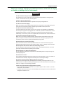
The following symbols are used on this instrument.
Warning: handle with care. Refer to the user’s manual or service manual. This symbol appears
on dangerous locations on the instrument which require special instructions for proper handling
or use. The same symbol appears in the corresponding place in the manual to identify those
instructions.
Electric shock, danger
Ground (earth) or functional ground terminal (do not use this terminal as a protective ground
terminal)
Alternating current
On (power)
Off (power)
Power-on state
Power-off state
iv
IM 2558A-01EN
Safety Precautions
Failure to comply with the precautions below could lead to injury
or death or damage to the instrument.
WARNING
Use the Instrument Only for Its Intended Purpose
This instrument is an AC voltage and current standard that generates AC voltage and AC
current. Use this instrument only for this purpose.
Check the Physical Appearance
Do not use the instrument if there is a problem with its physical appearance.
Use the Correct Power Supply
Make sure that the power supply voltage matches the instrument’s rated supply voltage and
that it does not exceed the maximum voltage range specified for the power cord.
Use the Correct Power Cord and Plug
To prevent electric shock and fire, be sure to use a power cord provided by YOKOGAWA.
The main power plug must be plugged into an outlet with a protective earth terminal. Do not
invalidate this protection by using an extension cord without protective earth grounding.
Additionally, do not use the power cord supplied with this instrument with another instrument.
Connect the Protective Grounding Terminal
Make sure to connect the protective earth to prevent electric shock before turning on the
power. The power cord that comes with the instrument is a three-prong type power cord.
Connect the power cord to a properly grounded three-prong outlet.
Do Not Impair the Protective Grounding
Never cut off the internal or external protective earth wire or disconnect the wiring of the
protective earth terminal. Doing so may result in electric shock or damage to the instrument.
Do Not Operate with Defective Protective Grounding or Fuses
Do not operate the instrument if the protective earth or fuse might be defective. Check the
grounding and the fuse before operating the instrument.
Do Not Operate in an Explosive Atmosphere
Do not operate the instrument in the presence of flammable gasses or vapors. Doing so is
extremely dangerous.
Do Not Remove Covers
Only qualified YOKOGAWA personnel should remove the instrument’s covers. The inside of
the instrument is extremely dangerous because parts of it have high voltages.
Ground the Instrument before Making External Connections
Securely connect the protective grounding before connecting to the target device or to an
external control unit. Before touching the target device, turn off this instrument and check that
there is no voltage or current being generated.
Install or Use the Instrument in Appropriate Locations
• Do not install the instrument outdoors or in locations subject to rain or water. Or, use the
instrument in such locations.
• Install the instrument so that you can immediately remove the power cord if an abnormal or
dangerous condition occurs.
IM 2558A-01EN
Safety Precautions
Connect Cables Correctly
This instrument can generate large voltage and current. If you do not connect the devices
correctly, not only will it damage the instrument or the target device, it may also lead to electric
shock or fire. Be careful when you connect the cables, and be sure to check the following
points.
Before generation (before turning on the output), check that:
• Cables have been connected to the instrument’s output terminals correctly.
Check that there are no voltage output cables that have been connected to the current
terminals.
Check that there are no current output cables that have been connected to the voltage
terminals.
• Cables have been connected to the target device correctly.
Check that there are no short circuits between voltage terminals or between the cables
connected to the voltage terminals.
• The cables are connected firmly to the current terminals.
• There no problems with the current terminals and the crimping terminals, such as the
presence of foreign substances.
During output (never touch the terminals or the connected cables when this instrument is on),
check that:
• There no problems with the current terminals and the crimping terminals, such as the
presence of foreign substances.
• The current terminals are not abnormally hot.
• The cables are connected firmly to the current terminals.
The terminal connections may become loose over time. If this happens, heat may be
generated due to changes in contact resistance. If you are going to take measurements
using the same setup for a long time, periodically check that the cables are firmly
connected to the terminals. (Be sure to turn off both this instrument and the target device
before you check the connections.)
After generation (immediately after the output is turned off)
After you generate a large voltage or current, voltage may remain for some time even after
you turn the output off. This residual voltage may lead to electric shock, so do not touch the
voltage or current terminals immediately after you turn the output off. The amount of time
that voltage remains varies depending on the target device.
CAUTION
Operating Environment Limitations
This product is a Class A (for industrial environment) product. Operation of this product in a
residential area may cause radio interference in which case the user will be required to correct
the interference.
vi
IM 2558A-01EN
Waste Electrical and Electronic Equipment
IM 2558A-01EN
Waste Electrical and Electronic Equipment (WEEE), DIRECTIVE 2002/96/EC
(This directive is valid only in the EU.)
This product complies with the WEEE Directive (2002/96/EC) marking requirement. This
marking indicates that you must not discard this electrical/electronic product in domestic
household waste.
Product Category
With reference to the equipment types in the WEEE directive Annex I, this product is classified
as a “Monitoring and control instruments” product.
Do not dispose in domestic household waste. When disposing products in the EU, contact your
local Yokogawa Europe B. V. office.
vii
Conventions Used in This Manual
Notes
The notes and cautions in this manual are categorized using the following symbols.
Improper handling or use can lead to injury to the user or damage to the
instrument. This symbol appears on the instrument to indicate that the user must
refer to the user’s manual for special instructions. The same symbol appears in
the corresponding place in the user’s manual to identify those instructions. In the
user’s manual, the symbol is used in conjunction with the word “WARNING” or
“CAUTION.”
WARNING
Calls attention to actions or conditions that could cause serious or fatal injury to
the user, and precautions that can be taken to prevent such occurrences.
CAUTION
Calls attention to actions or conditions that could cause light injury to the user
or cause damage to the instrument or user’s data, and precautions that can be
taken to prevent such occurrences.
Note
Calls attention to information that is important for the proper operation of the
instrument.
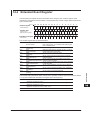
Characters That Appear on the 7-Segment LED
Because this instrument uses a 7-segment LED display, numbers, letters, and mathematical symbols
are displayed using special characters. For details, see section 1.3, “Digital Numbers and Characters.”
Symbols and Conventions Used in Procedural Explanations
The contents of the procedural explanations are indicated using the following symbols.
Procedure
Carry out the procedure according to the step numbers. All procedures are
written under the assumption that you are starting operation at the beginning
of the procedure, so you may not need to carry out all the steps in a procedure
when you are changing the settings.
Explanation This section describes the setup items and the limitations regarding the
procedures. It may not give a detailed explanation of the feature. For a detailed
explanation of the feature, see chapter 2.
<<Command Mnemonic>>
Indicates a communication command that corresponds to some of the features described on the
procedural explanation page.
Characters and Terminology Used in Procedural Explanations
Dial and Switches
Bold characters used in the procedural explanations indicate dials and switches on the panel.
viii
IM 2558A-01EN
1
Contents
Checking the Contents of the Package............................................................................................. ii
Safety Precautions............................................................................................................................ iv
Waste Electrical and Electronic Equipment..................................................................................... vii
Conventions Used in This Manual.................................................................................................. viii
Chapter 1 Component Names and Functions
1.1
1.2
1.3
Panel................................................................................................................................. 1-1
Dial and Switches.............................................................................................................. 1-3
Digital Numbers and Characters....................................................................................... 1-6
Chapter 2 Features
2.1
2.2
2.3
2.4
2.5
2.6
2.7
System Configuration........................................................................................................ 2-1
Output................................................................................................................................ 2-2
Output Divider................................................................................................................... 2-4
Deviation and Presets....................................................................................................... 2-5
Sweeping........................................................................................................................... 2-7
Synchronous Operation..................................................................................................... 2-8
Other Features.................................................................................................................. 2-9
Chapter 3 Preparation
3.1
3.2
3.3
3.4
3.5
3.6
Handling Precautions........................................................................................................ 3-1
Installing the Instrument.................................................................................................... 3-3
Connecting to the Power Supply....................................................................................... 3-6
Turning On and Off the Power Switch............................................................................... 3-7
Wiring Precautions............................................................................................................ 3-9
Connecting Cables.......................................................................................................... 3-10
Chapter 4 How to Use the SETUP Menu
4.1
4.2
4.3
SETUP Menu Tree Structure............................................................................................. 4-1
SETUP Menu and Dial Assignments................................................................................. 4-3
Entering and Displaying Values......................................................................................... 4-4
Chapter 5 Voltage and Current Generation
5.1
5.2
5.3
5.4
5.5
5.6
5.7
5.8
Selecting Whether to Ground the LO Terminal (COMMON Terminal)............................... 5-1
Setting the Frequency....................................................................................................... 5-2
Selecting the Voltage or Current Range............................................................................ 5-5
Main Voltage and Current Settings.................................................................................... 5-6
Dividing the Output............................................................................................................ 5-7
Turning the Output On and Off.......................................................................................... 5-8
Finely Adjusting the Output (Deviation and Preset)......................................................... 5-10
Sweeping......................................................................................................................... 5-12
2
3
4
5
6
7
8
9
10
11
12
13
14
15
16
App
Index
IM 2558A-01EN
ix
Contents
Chapter 6 Calibrating the Frequency Meter
6.1
6.2
6.3
6.4
6.5
6.6
6.7
6.8
Selecting Whether to Ground the LO Terminal (COMMON Terminal)............................... 6-1
Setting the Frequency....................................................................................................... 6-2
Selecting the Voltage or Current Range............................................................................ 6-3
Main Voltage and Current Settings.................................................................................... 6-4
Dividing the Output............................................................................................................ 6-5
Turning the Output On and Off.......................................................................................... 6-6
Finely Adjusting the Output (Deviation and Preset)........................................................... 6-7
Sweeping........................................................................................................................... 6-9
Chapter 7 Synchronous Operation
7.1
7.2
External Signal Input and Internal Signal Output.............................................................. 7-1
Synchronous Operation..................................................................................................... 7-3
Chapter 8 Other Features
8.1
8.2
8.3
8.4
Turning the Beep Sound On and Off................................................................................. 8-1
Error Log Display............................................................................................................... 8-2
Initializing the Settings....................................................................................................... 8-4
Displaying the Product Information................................................................................... 8-5
Chapter 9 USB Interface
9.1
9.2
USB Interface Features and Specifications....................................................................... 9-1
Connecting to the USB Interface....................................................................................... 9-2
Chapter 10 Ethernet Interface
10.1
10.2
10.3
Ethernet Interface Features and Specifications.............................................................. 10-1
Connecting to the Ethernet Interface............................................................................... 10-2
Configuring the 2558A Ethernet Settings........................................................................ 10-3
Chapter 11 GP-IB Option
11.1
11.2
11.3
11.4
GP-IB Interface Features and Specifications...................................................................11-1
Connecting to the GP-IB Interface...................................................................................11-3
Configuring the 2558A GP-IB Settings.............................................................................11-5
Responses to Interface Messages...................................................................................11-7
Chapter 12 Programming Overview
12.1
12.2
12.3
12.4
12.5
Messages........................................................................................................................ 12-1
Commands...................................................................................................................... 12-3
Responses...................................................................................................................... 12-5
Data................................................................................................................................. 12-6
Synchronization with the Controller................................................................................. 12-8
IM 2558A-01EN
Contents
chapter 13 Commands
13.1
13.2
13.3
13.4
13.5
13.6
13.7
13.8
13.9
13.10
13.11
List of Commands........................................................................................................... 13-1
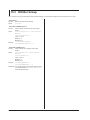
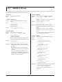
COMMunicate Group...................................................................................................... 13-3
DIVider Group................................................................................................................. 13-4
FREQuency Group.......................................................................................................... 13-5
OUTPut Group................................................................................................................ 13-6
DEViation Group............................................................................................................. 13-7
SOURce Group............................................................................................................... 13-8
STATus Group................................................................................................................. 13-9
SWEep Group............................................................................................................... 13-10
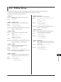
SYSTem Group..............................................................................................................13-11
Common Command Group........................................................................................... 13-13
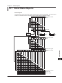
About Status Reports...................................................................................................... 14-1
Status Byte...................................................................................................................... 14-3
Standard Event Register................................................................................................. 14-4
Extended Event Register................................................................................................. 14-5
Output and Error Queues................................................................................................ 14-6
Chapter 15 Troubleshooting, Maintenance, and Inspection
15.1
15.2
15.3 15.4
15.5
15.6 15.7
15.8
Troubleshooting............................................................................................................... 15-1
Error Code Descriptions and Corrective Actions............................................................. 15-2
Communication Error Messages..................................................................................... 15-3
Instrument Error Detection and Clearance...................................................................... 15-7
Self-test........................................................................................................................... 15-8
Cleaning the Filter........................................................................................................... 15-9
Recommended Part Replacement.................................................................................15-11
Adjustment and Calibration............................................................................................15-11
Chapter 16 Specifications
16.1
16.2
16.3
16.4
16.5
16.6
16.7
Appendix
Range Generated............................................................................................................ 16-1
Accuracy.......................................................................................................................... 16-2
Functions......................................................................................................................... 16-4
External Input and Output............................................................................................... 16-5
Computer Interface.......................................................................................................... 16-5
General Specifications.................................................................................................... 16-6
External Dimensions....................................................................................................... 16-7
Appendix 1
Appendix 2
Appendix 3
Appendix 4
Appendix 5
Appendix 6
2
3
4
5
Chapter 14 Status Reports
14.1
14.2
14.3
14.4
14.5
1
Block Diagram..................................................................................................... App-1
Example of Using the 2558A to Calibrate an Analog Meter................................ App-2
Example of Using the 2558A to Calibrate a Power Meter................................... App-4
Phase Shift Feature............................................................................................ App-5
Factory Default Settings...................................................................................... App-6
About the IEEE 488.2-1992 Standard................................................................. App-7
6
7
8
9
10
11
12
13
14
15
16
Index
App
Index
IM 2558A-01EN
xi
Chapter 1
1.1
Component Names and Functions
1
Panel
Component Names and Functions
2
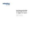
Front Panel
DEVIATION/PRESET section
Finely adjusts the output value
→ Sections 1.2, 5.7, and 6.7
3
REMOTE indicator
Illuminates when the 2558A is in remote
mode (controlled through communications)
→ Sections 9.1, 10.1, and 11.1
FREQUENCY/PHASE section
Sets and displays the frequency or phase angle
→ Sections 1.2, 5.2, and 6.2
Main setting section
Sets and displays the voltage or current level.
→ Sections 1.2, 5.4, and 6.4
4
OUTPUT indicator
Displays the voltage, current, or frequency.
→ Sections 5.6 and 6.6
Output unit indicator
Displays the output unit.
5
6
7
8
RANGE dial
Switches the voltage or
current range
→ Section 5.3 and 6.3
HIGH VOLTAGE indicator
Illuminates when the RANGE dial
is set to 300 V or 1000 V
→ Section 5.3 and 6.3
FREQUENCY dial
Switches the frequency
→ Sections 5.2 and 6.2
OUTPUT DIVIDER section
Divides the voltage or current
level or the frequency output
→ Sections 5.5 and 6.5
Power switch
Turns the output on and off
→ Section 3.4
Voltage terminals
Used to connect the included
measurement leads
→ Section 3.6
9
10
11
Current terminals
Used to connect the included
measurement leads
→ Section 3.6
12
LO TO EARTH indicator
Indicates the grounding state of the LO terminal.
Illuminates when SETUP EARTH is on
→ Section 5.1, and 6.1
13
OUTPUT section
Turns the voltage or current output on and off
→ Sections 1.2, 5.6 and 6.6
Switches remote mode (controlled through
communications) to local mode
→ Sections 9.1, 10.1, and 11.1
14
15
SWEEP section
Performs up or down sweeps
→ Sections 1.2, 5.8, and 6.8
16
App
Index
IM 2558A-01EN
1-1
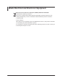
1.1 Front Panel, Rear Panel, and Top Panel
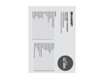
Rear Panel
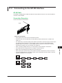
GP-IB connector (option)
Used to control the 2558A from a PC
→ Section 11.2
Ethernet port
Used to connect the 2558A to a network
(10BASE-T/100BASE-TX)
→ Section 10.2
USB port
Used to connect the 2558A to a PC that has a
USB interface and to control the 2558A with
USB-TMC commands
→ Section 9.2
External signal input terminal
Used to generate voltage or current on the
basis of an external oscillator frequency or
synchronize multiple 2558As
→ Section 7.1 and 7.2
Inlet holes
→ Section 3.2
Signal output terminals
Used to synchronize multiple 2558As
→ Sections 7.1 and 7.2
Power inlet
Connect the power cord.
→ Section 3.3
Top and Bottom Panels
Top panel
Bottom panel
Outlet holes
→ Section 3.2
1-2
IM 2558A-01EN
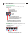
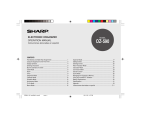
1.2
1
Dial and Switches
The FREQUENCY/PHASE section consists of a cursor switch (◄►), a VARIABLE dial, a 6-digit
FREQUENCY/PHASE display, and a unit indicator. These controls work differently depending on the
FREQUENCY dial setting.
FREQUENCY/PHASE display
Displays the set frequency, set phase angle, or measured frequency.
The following setting values or measured values are displayed
depending on the FREQUENCY dial.
• When set to 50, 60, or 400: The fixed frequency
• When set to VAR: Arbitrary frequency
• When set to EXT1: External oscillator frequency
• When set to EXT2 (PHASE): Phase angle
• FREQUENCY METER MIN: Minimum frequency
• FREQUENCY METER MAX: Maximum frequency
3
4
5
6
Unit indicator
Indicates the phase angle or frequency unit
• Phase angle: °
• Frequency: Hz
7
8
VARIABLE dial
Set the number of the selected digit in the range of 0 to 9.
Within the selectable range of frequencies or phase angles, carrying over
and borrowing occurs automatically. If the upper or lower limit of the range
is reached, turning the dial further will not change the number of the digit.
This dial is valid when the FREQUENCY dial is set to one of the following:
VAR, EXT2(PHASE), MIN/MAX(FREQUENCY METER)
9
10
Cursor switch
Selects the digit that you want to set. The number of the selected digit blinks. Flip the
switch to the left to select the next left digit. Flip the switch to the right to select the
next right digit. If the highest digit is selected, flipping the switch to the left will select
the lowest digit. If the lowest digit is selected, flipping the switch to the right will select
the highest digit. You can use this switch when the VARIABLE dial is valid.
11
12
Main Setting Section
The main setting section consists of four main setting dials, a 5-digit main setting display, and a unit
indicator. The decimal place varies depending on the RANGE dial setting.
Main setting display
Displays the voltage or current level. The
number of displayed digits varies depending on
the voltage or current range.
Component Names and Functions
2
FREQUENCY/PHASE Section
13
Unit indicator
Displays the voltage or current unit.
• Voltage: mV, V
• Current: mA, A
14
15
16
App
Main setting dials
Set the number of each digit on the main setting display in the range of 0 to 9.
Carrying over and borrowing occurs automatically up to 120% of the voltage
or current range. If the upper or lower limit of the range is reached, turning the
dial further will not change the number of the digit.
IM 2558A-01EN
Index
1-3
1.2 Dial and Switches
DEVIATION/PRESET Section
The DEVIATION/PRESET section consists of two deviation dials, a 4-digit DEVIATION display, a
PRESET switch, and a preset indicator.
DEVIATION display
Displays the deviation in reference to the main setting
Preset value indicator
Displays the deviation value set with the PRESET switch
PRESET switch
Set the deviation in reference to the main setting.
Deviation dial 2
Sets the hundredths digit of the deviation value display. You can turn this dial with less torque.
Deviation dial 1
Sets the tenths digit of the deviation value display
The deviation dial sets the number of each digit in the range of 0 to 9. Dial 1 changes the number in
increments of 2; Dial 2 changes the number in increments of 1. Carrying over and borrowing occurs
automatically up to ±20%. If the upper or lower limit of the range is reached, turning the dial further will
not change the number.
SWEEP Section
The SWEEP section consists of a SWEEP switch and a pair of UP and DOWN indicators for indicating
the sweep direction.
UP indicator
Illuminates when sweeping up
DOWN indicator
Illuminates when sweeping down
SWEEP switch
UP sweep
Flip the switch up to sweep up. Flipping the switch down
while sweeping up stops the sweeping (HOLD state).
DOWN sweep
Flip the switch down to sweep down. Flipping the switch up
while sweeping down stops the sweeping (HOLD state).
OUTPUT Section
The OUTPUT section consists of a OUTPUT switch and a pair of ON and OFF indicators.
ON indicator
Illuminates when voltage or current is being generated
OUTPUT switch
Local mode
Flip up to turn the output on.
Flip down to turn the output off.
Flipping this switch down in remote mode (controlled through
communications) causes the 2558A to switch to local mode.
OFF indicator
Illuminates when voltage or current is not being generated
1-4
IM 2558A-01EN
1.2 Dial and Switches
1
OUTPUT DIVIDER Section
n display
Indicates the numerator of the divider value
Component Names and Functions
The OUTPUT DIVIDER section consists of m and n dials for setting the divider value (n/m) and m and
n displays to show the value.
2
3
n dial
Sets the numerator, n, of the divider value. The range is 0 to m.
4
m dial
Sets the denominator, m, of the divider value. The range is 4 to 15.
Turning the m dial resets numerator n to the denominator m value.
5
m display
Indicates the denominator of the divider value
6
7
8
9
10
11
12
13
14
15
16
App
Index
IM 2558A-01EN
1-5
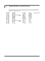
1.3
Digital Numbers and Characters
Because this instrument uses a 7-segment LED display, numbers, letters, and mathematical symbols
are displayed using special characters in the manner shown below. Some of the characters shown
below are not used by this instrument.
power
lowercase
lowercase
1-6
IM 2558A-01EN
Chapter 2
2.1
Features
1
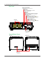
System Configuration
2
Features
PC
Command control
GP-IB
USB (USB-TMC)
Ether (VXI-11)
3
4
Communication interface
5
6
2558A
EXT OSC
EXT1, EXT2(I(cos))
EXT2(Q(sin))
I(cos)
Q(sin)
7
2558A
Slave
8
VOLTAGE CURRENT
OUTPUT OUTPUT
Hi
Lo
Hi
Lo
9
DUT (output target)
10
11
12
13
14
15
16
App
Index
IM 2558A-01EN
2-1
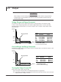
2.2
Output
CAUTION
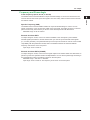
When voltage or current is being generated, if a load that would cause the range generated
indicated below to be exceeded is connected, the instrument will detect the abnormal load
and turn off the output.
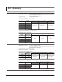
Voltage Range and Range Generated
The maximum output at each voltage range is shown in the figure below. The maximum output
is 120% of each voltage range rating. If you set the voltage range to 300 V or 1000 V, the HIGH
VOLTAGE indicator will illuminate. If you set the voltage to 150 V or higher, a high-voltage caution
beep will sound.
Current
3A
Voltage
Range
Range generated
100 mV
1V
10 V
100V
300 V
1000 V
0.3 A
0.1 A
6 mA
12 V120 V 360 V
1200 V
Range
1
Generated
0 mV to 120.00 mV
0 V to 1.2000 V
0 V to 12.000V
0 V to 120.00 V
0 V to 360.0 V
0 V to 1200.0 V
Maximum
2
Output
—
0.5 A or higher
approx. 3 A
approx. 0.3 A
approx. 0.1 A
approx. 6 mA
Voltage 1 Generates 144% of the range when used
with deviation (–20%)
2 At 1% to 120% of the range
Current Range and Range Generated
The maximum output at each current range is shown in the figure below. The maximum output is 120%
of each current range rating.
Voltage
15 V
Range generated
3V
0.6 V
1.2 A
12 A
60 A
Current
Current
Range
Range
1
Generated
Maximum
2
Output
100 mA
1A
10 A
50 A
0 mA to 120.00 mA
0 A to 1.2000 A
0 A to 12.000 A
0 A to 120.00 A
approx. 15 V
approx. 15 V
approx. 3 V
approx. 0.6 V
1 Generates 144% of the range when used
with deviation (–20%)
2 At 1% to 120% of the range
Turning the Output On and Off
There are two output modes: OFF and ON.
OFF:The output is disconnected. The specified output level is not generated.
ON:The output is connected, and the specified output level is generated. During output, the output
display shows the voltage or current.
2-2
IM 2558A-01EN
2.2 Output
1
Frequency and Phase Angle
Fixed Frequency (50 Hz, 60 Hz, or 400 Hz)
2
Features
The 2558A uses its internal oscillator to output sinusoidal voltage or current. 50 Hz and 60 Hz are
used for devices that receive power line signals. 400 Hz is mainly used for meters used in aircrafts
and marine vessels.
3
Specific Frequency (VAR)
The 2558A uses its internal variable oscillator to output sinusoidal voltage or current. You can
specify a frequency of your choice using a dial on the front panel. The setting is shown on the front
panel. The accuracy is the same if you set one of the fixed frequencies with this feature.
Selectable range: 40 Hz to 1000 Hz
4
5
External Oscillator EXT1
To output voltage or current, connect an external oscillator to the I side (EXT1) of the 2558A’s
external signal input terminal. Use this feature when you need to synchronize with other signals
(i.e., function generator). The phase between input and output is reversed in order to accommodate
compatibility with the predecessor model, 2558. The 2558A measures the external oscillator
frequency and shows it on the front panel.
Input range: 40 Hz to 1000 Hz
External Oscillator EXT2 (PHASE)
To output voltage or current, connect the two signal outputs from another 2558A. Use this feature to
perform synchronous operation between multiple 2558As. You can set the phase angle according to
the measurement system. The setting is shown on the front panel.
Selectable range: –180.000° to +359.999°
Input range: 40 Hz to 1000 Hz. The frequency is not shown on the front panel.
6
7
8
9
10
11
12
13
14
15
16
App
Index
IM 2558A-01EN
2-3
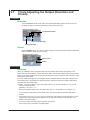
2.3
Output Divider
When calibrating the target meter, the output divider feature divides the voltage or current level or the
frequency into as many points as you need to calibrate. You can set the main setting to the maximum
indication on the target meter, and vary the divider value to calibrate the various points on the meter.
Divider value range: n/m where n = 0 to m and m = 4 to 15
Setup example: When the main setting is 10 A, n is 2, and m is 4,
output value = 10 A×2/4 = 5 A (divider value: 1/2)
Main setting = 10 A
n=0
m=4
Ammeter
0A
n=2
m=4
n=4
m=4
Ammeter
5A
Ammeter
10 A
Frequency Output Divider
If the frequency is set to FREQUENCY METER MIN or FREQUENCY METER MAX, the oscillation
frequency is divided and output. The main setting is not divided.
For example, if the MIN frequency is 45 Hz, the MAX frequency is 65 Hz, and the main setting is 100 V,
the following result is obtained.
At n =0 and m = 4, the output voltage is 100 V, and the frequency meter shows 45 Hz.
At n =2 and m = 4, the output voltage is 100 V, and the frequency meter shows 55Hz.
At n =4 and m = 4, the output voltage is 100 V, and the frequency meter shows 65Hz.
In this example, the frequency width of 20 Hz is divided into four parts and output at 5 Hz intervals.
The voltage level is not divided.
2-4
IM 2558A-01EN
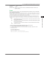
2.4
1
Deviation and Presets
2
This feature is used to check the relative error (deviation) of the meter scale calibration. If the meter
needle is not pointing accurately to the appropriate scale mark, you can turn a deviation dial on the
front panel to finely adjust the voltage or current output level or the frequency so that the needle points
accurately to the mark. The amount of fine adjustment is displayed as the deviation.
Deviation setting range: ±20.00%
Setup example:
Features
Deviation
3
4
Main setting = 10 A, divider value n/m = 1
Main setting = 10 A
5
6
Use the deviation dial to align
the meter needle to the accurate
scale position.
Error (deviation)
7
Ammeter
9.97 A
8
9
10
Ammeter
10 A
11
The deviation is –0.30%.
In the example above, before fine adjustment, the meter needle is pointing to 9.97 A, which is 0.30%
smaller than the 10 A current output from the 2558A. The deviation polarity (the sign) of the 2558A
indicates whether the target device indication is larger or smaller than the accurate position. In this
example, because the meter is pointing to a value that is 0.30% smaller than the 2558A output value,
the 2558A displays –0.30%.
Deviation at Each Calibration Point
When the deviation feature is used in conjunction with the output divider feature explained in section
2.3, you can check at each calibration point the deviation in reference to the maximum scale value.
Note that if the frequency is set to FREQUENCY METER MIN or FREQUENCY METER MAX, the
deviation is in reference to the span.
When the maximum scale value is 10 A, 1% is 0.1 A.
If you are using the output divider feature at n = 2 and m = 10, when 2 A is being output, 1% will
also be 0.1 A.
12
13
14
15
16
App
Index
IM 2558A-01EN
2-5
2.4 Deviation and Presets
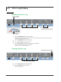
Presets
Deviation presets can be used to make the meter indicate values that are short of the accurate scale
positions when you change the output divider setting.
You can use this feature to calibrate a meter when using the output divider feature to calibrate the
points in increasing or decreasing order.
5%: When calibrating in increasing order, the deviation is set to +5.00%.
When calibrating in decreasing order, the deviation is set to –5.00%.
2%: When calibrating in increasing order, the deviation is set to +2.00%.
When calibrating in decreasing order, the deviation is set to –2.00%.
0%: The deviation is cleared when the divider value is changed.
OFF: The specified deviation is retained even when the divider value is changed.
Example when calibrating
in increasing order
Preset (5%)
Main setting = 10 A
Indicates a point that is
short of the calibration point
by the preset amount
Ammeter
4.5 A
Use the n dial to move
the meter needle up.
Indicates a point that is
short of the calibration point
by the preset amount
Ammeter
9.5 A
In the above example, the 2558A is generating –5.00% of the output setting. To calibrate the scale,
turn a deviation dial to move the meter needle to the correct position. For details on how to read the
deviation, see “Deviation” on the previous page.
2-6
IM 2558A-01EN
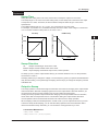
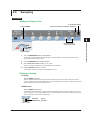
2.5
1
Sweeping
2
Features
The sweep feature moves the meter needle from the minimum scale value to 120% of the maximum
scale value at a constant speed. It is used to check whether the needle is sticky when it moves. You
can select the sweep time depending on the meter type. To sweep a wide-angle meter, you can select
a long sweep time to move the needle slowly.
Sweep time: 16 s, 32 s, or 64 s
3
4
Main setting = 10 A
5
Sweeps the needle over
the specified time.
UP sweep
6
7
Ammeter
0 A to 12 A
8
DOWN sweep
Ammeter
12 A to 0 A
9
10
When sweeping up, sweeping is performed up to 120% of the maximum scale value.
11
12
13
14
15
16
App
Index
IM 2558A-01EN
2-7
2.6
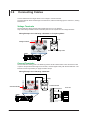
Synchronous Operation
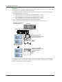
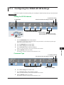
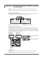
You can connect multiple 2558As together and output voltage or current in sync with the frequency of
the master 2558A.
Synchronous operation is used when using two 2558As, one as a voltage generator and the other as
a current generator, to calibrate a power meter or when using two 2558As in parallel to generate large
current.
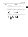
External I/O Connection
Connect the signal output terminals (I and Q) on the rear panel of the master 2558A to the external
input terminals (I and Q) of the slave 2558A.
I(cos)
I(cos)
Q(sin)
Q(sin)
I
Q
I
Q
EXT 1
OSC OUTPUT
EXT OSC INPUT
2558A (Master)
Setup example:
Frequency set to 60 Hz
2-8
I
Q
I
Q
EXT 1
OSC OUTPUT
EXT OSC INPUT
2558A (Slave1)
Setup example:
Frequency set to EXT2
I
Q
EXT 1
EXT OSC INPUT
I
Q
OSC OUTPUT
2558A (Slave2)
Setup example:
Frequency set to EXT2
IM 2558A-01EN
2.7
1
Other Features
2
Beeps are used to indicate the operation status of the device. You can turn it on and off from the
SETUP menu.
You can turn the beep sound on or off for the following notifications. You cannot change the volume.
• When an error is detected during a self-test executed at power-on or executed manually (error
codes: E.911 to E950)
• When the voltage output is set to 150 V or higher
• When a sweep operation is held
Features
Turning the Beep Sound On and Off
3
4
5
You can not turn off the beep sound for the following notifications.
• When the cooling fan stops (error code: E.901)
• When an abnormal temperature is detected (error code: E.902 to E.903)
• When an internal power supply error is detected (error code: E.904)
6
Error Log Display
The error log keeps a record of error codes that occur in communication and self-tests while the 2558A
is on. You can display the error log from the SETUP menu. The error log is cleared when the power is
turned off.
Initialization
7
8
9
You can initialize the 2558A settings to their factory defaults. You can execute initialization from the
SETUP menu.
GP-IB and Ethernet settings are not initialized.
For a list of factory default settings, see appendix 5.
10
Product Information Display
11
You can view the firmware version, serial number, and so on. You can view the product information
from the SETUP menu.
• Firmware version
• Logic program version
• Boot program version
• Serial number
12
13
14
15
16
App
Index
IM 2558A-01EN
2-9
Chapter 3
3.1
Preparation
1
Handling Precautions
2
Safety Precautions
If you are using the 2558A for the first time, make sure to read “Safety Precautions,” on pages iv to vi.
Do not remove the case from the instrument. Some parts of the instrument use high voltages and
are extremely dangerous. For internal inspection and adjustment, contact your nearest YOKOGAWA
dealer.
Preparation
Do Not Remove the Case
3
4
5
Unplug If Abnormal Behavior Occurs
If you notice smoke or unusual odors coming from the instrument, immediately turn off the power and
unplug the power cord. Also, turn off the power to the target device that are connected to the output
terminals. Then, contact your nearest YOKOGAWA dealer.
6
Do Not Damage the Power Cord
7
Nothing should be placed on top of the power cord. The power cord should also be kept away from
any heat sources. When removing the plug from the power outlet, do not pull on the cord. Pull from the
plug. If the power cord is damaged, purchase a replacement with the same part number as the one
indicated on page ii.
Correct the Problem If Output Is Forcibly Turned Off
If an abnormality is detected in the internal circuit due to a voltage or current overloading, voltage or
current output oscillation, and so on, the 2558A will turn off the output and display a warning message
(No. 031 to 035) on the output display.
In the case of voltage output, remove the cause of the problem, such as the external load, and turn the
output on again.
In the case of current output, remove the cause of the problem, such as the external load, short the
current terminals, and turn the output on again.
If the output still turns off after you have corrected the problem, the 2558A may be malfunctioning.
Contact your nearest YOKOGAWA dealer.
Turn the Power Switch Off If Overheat is Detected
If internal overheating is detected due to a fan malfunction, and so on, the 2558A will turn off the
output, display an error code (No. 901 to 903), and beep intermittently. If this happens, immediately
turn the power switch off. Check that the inlet or outlet holes for the cooling fan are not blocked and
that there is adequate space around the 2558A. Check for and remove any foreign objects that are
caught in the filter on the rear panel. If the same error code appears when you turn the power switch
on after waiting at least an hour, the 2558A may be malfunctioning. Contact your nearest YOKOGAWA
dealer.
8
9
10
11
12
13
14
15
16
App
Index
IM 2558A-01EN
3-1
3.1 Handling Precautions
General Handling Precautions
Do Not Place Objects on Top of the Instrument
Never place other instruments or any objects containing water on top of it. Doing so may damage the
instrument. For details on stacking the 2558A, see section 3.2.
Keep Electrically Charged Objects Away from the Instrument
Keep electrically charged objects away from the input and output terminals. They may damage the
internal circuitry.
Unplug during Extended Non-Use
Turn off the instrument and remove the power cord from the outlet.
When Carrying the Instrument
Use two people to carry this instrument. Firmly hold the handles on the side of the case. The
instrument weighs approximately 20 kg (the center of gravity is somewhat toward the back).
Be careful of injury.
In addition, be sure to turn off the power switch and remove the power cord and other connected
cables before carrying the instrument.
When Cleaning the Instrument
When cleaning the case or the operation panel, turn the instrument and remove the instrument’s power
cord from the outlet. Then, wipe the instrument lightly with a clean dry cloth. Do not use chemicals
such as benzene or thinner. Doing so may cause discoloring and deformation.
3-2
IM 2558A-01EN
3.2
1
Installing the Instrument
2
WARNING
CAUTION
3
Preparation
• Do not install the instrument outdoors or in locations subject to rain or water.
• Install the instrument so that you can immediately remove the power cord if an abnormal or
dangerous condition occurs.
4
5
If you block the outlet holes on the top and bottom or the inlet holes on the rear of the
instrument, the instrument will become hot and may break down.
6
Installation Conditions
7
Install the instrument in a place that meets the following conditions.
Well-Ventilated Location
Outlet holes are located on the top and bottom of the instrument. There are also inlet holes on the
rear. To prevent internal overheating, allow for enough space around the instrument (see the figure
below), and do not block the inlet and outlet holes.
8
9
20 cm or more
10
When connecting cables, allow for enough space, above and beyond the space shown in the figure
above, to carry out the procedure.
11
Ambient temperature and humidity
Ambient temperature
Ambient humidity
5°C to 40°C
20% RH to 80% RH (no condensation)
12
Note
Condensation may form when the instrument is moved from a low temperature or humidity environment to a
high temperature or humidity environment, or when there is a sudden change in temperature. In such cases,
before you use the instrument, allow it to adjust to the surrounding temperature for at least an hour.
If you transport the instrument in its packing box, to prevent condensation, allow it to adjust to the new
ambient temperature for at least an hour before taking it out of the box.
13
14
15
16
App
Index
IM 2558A-01EN
3-3
3.2 Installing the Instrument
Installation Position
Desktop
Install the instrument on a stable surface that is level in all directions and that is not slippery.
The supplied rubber stoppers can be attached to the feet at the rear of the instrument to prevent the
instrument from sliding. You can install the instrument in a tilted position using the movable legs.
WARNING
•
•
•
•
Do not adjust the movable legs in an unstable condition.
Do not place the instrument in any position other than those shown in the above figures.
Do not stack the instruments with the movable legs pulled out.
Only one instrument can be stacked on top of another. Do not stack multiple instruments
on top of one instrument.
Rubber leg cap
A9088ZM
Foot at the rear of
the instrument
Note
If you attach the front rubber leg cap, you will not be able to stack the 2558A.
3-4
IM 2558A-01EN
3.2 Installing the Instrument
1
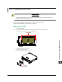
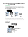
Rack Mounting
To rack-mount the instrument, use the separately sold rack mount kit.
Item
Model 751535-E3 Rack mount kit (for mounting one 2558A on an EIA standard rack)
Model 751535-J3 Rack mount kit (for mounting one 2558A on a JIS standard rack)
Model
751535-E3
751535-J3
An outline of the mounting procedure is given below. For detailed instructions, see the manual that
is included with the rack mount kit.
of the instrument near the front.
4. Place seals over the feet and handle attachment holes.
5. Attach the rack mount kit to the instrument.
6. Mount the instrument on a rack.
3
Preparation
1. Remove the handles from both sides of the instrument.
2. Remove the four feet from the bottom of the instrument.
3. Remove the four seals covering the rack mount attachment holes. The holes are on the sides
2
4
5
6
7
8
How to remove a handle cover
Note
• When rack-mounting the instrument, allow at least 5cm of space around the top panel outlet holes to
prevent internal heating. Allow at least 20 cm around the rear panel inlet holes.
• Make sure to provide adequate support from the bottom of the instrument. The support should not block
the inlet and outlet holes.
• Store the removed parts in a safe place.
• When rack-mounting the instrument, remove the feet from the rear of the instrument if they are coming
into contact with the rack and are thus preventing you from rack-mounting the instrument. After you have
rack-mounted the instrument, re-attach the feet to the rear of the instrument.
• Dials and current terminals protrude further out than the front panel position. Make sure you do not hit
them against the rack when mounting the instrument.
9
10
11
12
Do Not Install the Instrument in the Following Kinds of Places
•
•
•
•
•
•
•
In direct sunlight or near heat sources
In an environment with excessive amounts of soot, steam, dust, or corrosive gas
Near strong magnetic field sources
Near high-voltage equipment or power lines
In an environment that is subject to large levels of mechanical vibration
On an unstable surface
Outdoors or in locations subject to rain or water
13
14
15
16
App
Index
IM 2558A-01EN
3-5
3.3
Connecting to the Power Supply
Before Connecting the Power Supply
Make sure to follow the warnings below when connecting the power supply. Failure to do so may
cause electric shock or damage to the instrument.
WARNING
• Make sure that the power supply voltage matches the instrument’s rated supply voltage
and that it does not exceed the maximum voltage range specified for the power cord.
• Connect the power cord after checking that the power switch of the instrument is turned off.
• To prevent electric shock and fire, use a power cord for this instrument provided by
YOKOGAWA.
• Make sure to connect protective earth grounding to prevent electric shock. Connect the
power cord to a three-prong power outlet with a protective earth terminal.
• Do not use an ungrounded extension cord. If you do, the instrument will not be grounded.
• If an AC outlet that conforms to the supplied power cord is unavailable and you cannot
ground the instrument, do not use the instrument.
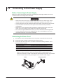
Connecting the Power Cord
1. Check that the power switch (POWER) on the front panel of the instrument is turned off.
2. Connect the power cord plug to the power inlet on the rear panel.
3. Connect the other end of the cord to an outlet that meets the following conditions. Use a
grounded three-prong outlet.
Item
Rated supply voltage*
Permitted supply voltage range
Rated supply frequency
Permitted supply frequency range
Maximum power consumption
100 VAC to 120 VAC, 200 VAC to 240 VAC
90 VAC to 132 VAC, 180 VAC to 264 VAC
50 Hz/60 Hz
48 Hz to 63 Hz
Approx. 200 VA
*This instrument can use a 100 V or a 200 V power supply. The maximum rated voltage
differs according to the type of power cord. Check that the voltage supplied to the
instrument is less than or equal to the maximum rated voltage of the power cord provided
with the instrument before using it (see page ii for the maximum rated voltage).
2558A
Three-prong outlet
3-6
IM 2558A-01EN
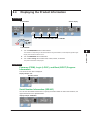
3.4
1
Turning On and Off the Power Switch
2
Before Turning On the Power, Check That:
• The instrument is installed properly. → section 3.2, “Installing the Instrument”
• The power cord is connected properly → see section 3.3, “Connecting to the Power Supply”
3
Preparation
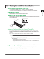
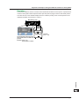
Power Switch Location
The power switch is located in the lower left of the front panel.
4
Turning On and Off the Power Switch
The power switch is a push button. Press the button once to turn the instrument on and press it again
to turn the instrument off.
2558A
OFF
ON
5
6
7
8
9
Operations Performed When the Power Is Turned On
When the power switch is turned on, a self-test starts automatically. When the self-test completes
successfully, the instrument will be configured with the settings that were in use immediately before
the power was turned off. For the settings that are retained even when the power is turned off, see
appendix 5.
Before using the instrument, make sure that the self-test completes successfully.
10
11
Note
• After turning the power switch off, wait at least 10 seconds before you turn it on again.
When the Power-on Operation Does Not Finish Normally
• If the instrument does not operate as described above when the power switch is turned on, turn the power
switch off, and then:
• Check that the power cord is securely connected.
• Check that the correct voltage is coming to the power outlet. → section 3.3, “Connecting the Power
Supply”
• Initialize the instrument. See section 8.3.
• If the instrument still does not work properly, contact your nearest YOKOGAWA dealer for repairs.
• If an error code is displayed, check the information in section 15.2, and take the appropriate actions.
To Generate Accurate Output
• Allow the instrument to warm up for at least 30 minutes after turning on the power switch.
• Keep the OUTPUT switch turned off during warm-up.
After warm-up is complete, turn the OUTPUT switch on.
12
13
14
15
16
App
Index
IM 2558A-01EN
3-7
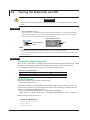
3.4 Turning On and Off the Power Switch
Operations Performed When the Power Is Turned Off
After the power is turned off, the instrument stores the setup parameters in its memory before shutting
down. The same is true when the power cord is disconnected from the outlet. The next time the power
is turned on, the instrument powers up using the stored settings (for the settings that are stored, see
appendix 5).
3-8
IM 2558A-01EN
3.5
1
Wiring Precautions
2
WARNING
3
Preparation
• Ground the instrument before connecting the instrument to the target device. The power
cord that comes with the instrument is a three-prong type power cord. Insert the power cord
into a grounded three-prong outlet.
• Be sure to turn off the output before connecting or disconnecting the target device.
• To prevent damage that would occur if the OUTPUT switch is flipped inadvertently during
wiring, check that the output setting dial is at 0000.
• If the voltage output exceeds 33 Vrms or 46.7 Vpeak, there is a danger of electric shock
due to the high voltage. Be extremely careful.
• Make sure to fasten the current output terminal screws securely so that cables do not come
loose.
• Only use cables whose conductive parts are covered for connecting to the voltage output
terminals. Exposed conductive parts can lead to electric shock.
• Do not use cables whose conductive parts are exposed due to tears in the insulation or
broken cables as they may lead to electric shock.
• When connecting cables to the target device, only use cables that have safety terminals
that cover their conductive parts. Using a terminal with bare conductive parts (such as a
banana plug) can be dangerous if the terminal comes loose.
• If a large capacitive load or oscillating circuit is connected to the voltage terminals, the
output may oscillate and cause high voltage to appear at the voltage output terminals. If the
output oscillates, turn it off immediately.
• If a large inductive load or oscillating circuit is connected to the current terminals, the output
may oscillate and cause high voltage to appear at the current output terminals. If the output
oscillates, turn it off immediately.
4
5
6
7
8
9
10
11
CAUTION
12
• Use cables that have adequate margins of withstand voltage and current capacity with
respect to the voltage or current to be generated.
Example: To use a current of 20 A, use copper wires that have a conductive crosssectional area of 4 mm2 or greater.
• When outputting current from the current terminals, do not open the current terminals.
Doing so will trigger an electric shock protection feature, and the output will turn off.
• When outputting voltage from the voltage terminals, do not short the voltage terminals.
Doing so will trigger an electric shock protection feature, and the output will turn off.
13
14
15
16
App
Index
IM 2558A-01EN
3-9
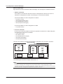
3.6
Connecting Cables
Connect cables from the target device to the voltage or current terminals.
To prevent electric shock and damage to the instrument, follow the warnings given in section 3.5, “Wiring
Precautions.”
Voltage Terminals
The terminals are safety banana jacks (female) that are 4 mm in diameter.
Only insert safety terminals whose conductive parts are not exposed into the voltage terminals.
Wiring Example for Calibrating a Voltmeter or Frequency Meter
HI
LO (±)
Voltage terminals
Voltmeter or frequency meter
2558A
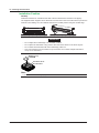
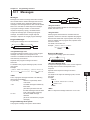
Current Terminals
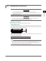
The terminals are binding posts. The fastening screws are M6. Either wind the wire around the screw
or pass a crimped terminal through the screw hole, and then tighten firmly with the terminal knob. The
terminal or knob may break if you apply excessive torque.
Wiring Example for Calibrating a Ammeter
HI
LO (±)
Current terminal
Ammeter
2558A
3-10
Terminal base
Unit: mm
7
Current terminals
IM 2558A-01EN
3.6 Connecting Cables
1
CAUTION
2
• Confirm that no foreign materials are caught in the contact area between the current
terminal and the cable.
• Periodically confirm that the current terminals are not loose and that there are no foreign
materials caught in the contact area between the current terminal and the cable.
3
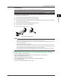
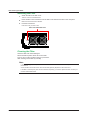
To connect a cable with a round crimped terminal to a current terminal, follow the procedure below.
1. Turn the current terminal knob to remove it.
Terminal base
Preparation
Connecting to a Round Crimped Terminal
4
5
Knob
6
Current terminal
7
2. Insert the screw of the knob into the crimped terminal, and then tighten firmly with the terminal
knob. The terminal or knob may break if you apply excessive torque.
8
9
Crimped terminal
10
11
12
13
14
15
16
App
Index
IM 2558A-01EN
3-11
Chapter 4
4.1
How to Use the SETUP Menu
1
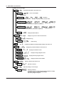
SETUP Menu Tree Structure
2
The SETUP menu appears when you turn the FREQUENCY dial and select SETUP.
This section describes the types and contents of the menu items using a tree diagram.
3
4
How to Use the SETUP Menu
5
SETUP
SWEEP
TIME
Sweep time
Value 16 s
32 s
64 s
EARTH
7
Set whether to ground the LO terminal. See sections 5.1 and 6.1.
MODE
6
Set the sweep time. See sections 5.8 and 6.8.
Ground or no ground
9
Set the beep sound. See section 8.1.
10
Value on (ground)
oFF (no ground)
BEEP
MODE
On or off
11
Value on
oFF
GPIB
8
Set the GP-IB conditions (option). See section 11.3.
ADRS
12
Address
Value 0 to 30
TYPE
13
Command type
Value NORM (IEEE488.2)
14
COMP (2558 compatible)
15
To LAN on the next page
16
App
Index
IM 2558A-01EN
4-1
4.1 SETUP Menu Tree Structure
To GPIB on the previous page
LAN
Set the Ethernet address. See section 10.3.
DHCP
Value on (use)
oFF (not use)
Use or not use DHCP.
IP.0 to 3
IP address
Value 0.0.0.0 to 255.255.255.255
Example: 192 (IP.0).168 (IP.1).0 (IP.2).1 (IP3)
MASK. 0 to 3
Value 0.0.0.0 to 255.255.255.255
Example: 255 (MASK.0).255 (MASK.1).255 (MASK.2).0 (MASK.3)
Subnet mask
GATE.0 to 3
Value 0.0.0.0 to 255.255.255.255
Example: 255 (GATE.0).255 (GATE.1).255 (GATE.2).0 (GATE.3)
MAC
ERROR
LOG
CLEAR
INIT
Displays the MAC address
Displays a log of error codes. See section 8.2.
Displays the log
Clears the log
Initializes the 2558A to its factory default settings. See section 8.3.
INFO
FIRM
LOGIC
BOOT
SER.NO
TEST
SELF
CAL
Displays the product information. See section 8.4.
Displays the firmware version
Displays the logic program version
Displays the boot program version
Displays the device serial number
Execute a self-test. See section 15.5.
Executes a self-test
Adjust the voltage or current range.
PASS
4-2
Default gateway
Enter the password.
For details on how to change the password and adjust the voltage
and current ranges, see the following webpage.
http://www.yokogawa.com/ymi/
IM 2558A-01EN
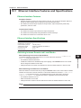
4.2
1
SETUP Menu and Dial Assignments
When the SETUP menu is displayed, only the dials and switches for selecting menu and display items
can be used. You cannot use the other dials and switches. Displays that are not used in the SETUP
menu turn off.
Select the SETUP Menu.
Displays the SETUP menu (the first level in the tree diagram of
section 4.1) Turn the VARIABLE dial to select a menu.
Example: SWEEP, LAN, INFO
3
4
How to Use the SETUP Menu
Setup menu item
Displays a SETUP menu item (the second level in the tree diagram of section 4.1)
Turn a main setting dial to select an item.
Example: In the case of LAN, select DHCP, IP, MASK, etc.
5
The values of a SETUP menu item
Displays the value or information of a SETUP menu item. See section 4.3.
If there is a value, turn a deviation dial to set the value.
Flip the PRESET switch up or down to confirm the selected value.
When the value has not been confirmed, all the PRESET LEDs light. When
it has been confirmed, all the PRESET LEDs turn off.
Example: ON/OFF, a value, etc.
2
6
7
Auxiliary information display
Displays the auxiliary information of a SETUP menu item when
available
Example: Error code in the error log
8
9
10
11
12
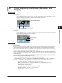
Select SETUP.
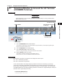
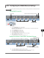
How SETUP Menu Items Are Displayed
13
When There Are No Items (INIT)
Items are not displayed.
14
When There Is a Single Item (SWEEP, BEEP, etc.)
The appropriate item is displayed. You do not use the main setting dials.
When There Are Multiple Items
Turn a main setting dial to display the appropriate item. You can use any of the main setting dials.
When a Single Item Has Four Sub Items (LAN IP, MASK, etc.)
Turn the right-most main setting dial to display the four sub items of all items one at a time.
Example: DHCP→IP.0→IP.1→IP.2→IP.3→MASK.0→MASK.1. . .
Turn any of the other three main setting dials to display one of the four sub items of all items one at
a time.
15
16
App
Example: DHCP→IP.0→MASK.0→GATE.0. . .
Index
IM 2558A-01EN
4-3
4.3
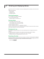
Entering and Displaying Values
The following methods are available in entering and displaying values depending on the SETUP menu
item.
• Selecting parameters
• Entering values
• Displaying the log
• Executing a function
Selecting Parameters
Turn a deviation dial to select the parameter.
You can use either deviation dial.
Example: ON/OFF, 16 s/32 s/64 s, etc.
Entering Values
Turn the deviation dials to enter a value.
Turn the deviation dial 1 to enter the tens digit.
Turn the deviation dial 2 to enter the ones digit.
The dial 2 changes the value by 1.
The dial 1 changes the value by 1 or 2 depending on the item.
Carrying over and borrowing occurs automatically. When the upper or lower limit is reached, the value
will no longer change even if you turn the dial further.
Displaying the Log
The availability of logging information and a number indicating the order of logging information are
displayed.
The logging information is indicated on the auxiliary information display (OUTPUT display).
If logging information is available, turn the deviation dial to switch the display.
Example: NO (none), 3.10 (displaying the third one out of 10)
Executing a Function
For items that represent functions that are to be executed, such as INIT and TEST, EXEC is displayed.
Depending on the item, executing the function will initialize the settings or clear the logging information.
You cannot undo it, so make sure it is okay to execute the function in advance.
EXEC display
4-4
IM 2558A-01EN
Chapter 5
5.1
Voltage and Current Generation
Selecting Whether to Ground the LO Terminal
(COMMON Terminal)
Procedure
2
3
CAUTION
If the target device is not grounded, ground the LO terminal (ON). If it is not grounded (OFF),
electric shock may occur.
4
4. Confirm the setting.
2. Select EARTH.
1
5
Voltage and Current Generation
Turns off when the setting
is confirmed
6
7
8
3. Turn either dial to
select ON or OFF.
9
1. Select SETUP.
10
1. Turn the FREQUENCY dial to select SETUP.
The indicator corresponding to the selected SETUP range illuminates, and the frequency/phase angle
display area shows the SETUP menu.
11
2. Turn the VARIABLE dial to select EARTH.
3. Turn the deviation dial to select ON or OFF.
12
When you change the setting, all four preset indicators will illuminate.
4. Flip the PRESET switch up or down.
The setting is confirmed, and all the preset indicator turn off.
When you turn it on, the LO TO EARTH indicator will illuminate.
13
Explanation
14
Set whether to ground the LO terminal of the voltage and current output.
ON: The LO terminal is grounded.
OFF:The LO terminal is not grounded.
If one of the terminals on the output target is grounded to avoid errors caused by a ground loop,
connect the LO terminal of the 2558A to the terminal that is grounded, and set the LO terminal to “no
ground” (OFF). If the target device is not grounded, ground the LO terminal (ON). If the LO terminals
of multiple 2558As are connected in parallel, ground the LO terminal of a single 2558A (set to ON) and
leave the others ungrounded (set to OFF).
16
App
<<Command Mnemonic>>
:SYSTem:EARTh <Boolean>
IM 2558A-01EN
15
Index
5-1
5.2
Setting the Frequency
Procedure
Selecting a Fixed Frequency (50 Hz, 60 Hz, or 400 Hz)
Turn the FREQUENCY dial to set the output frequency to 50, 60, or 400 (Hz).
The indicator corresponding to the selected frequency and the Hz unit indicator illuminate. In addition, the
selected frequency is displayed.
The specified frequency
Unit
Select 50, 60, or 400 (Hz).
Selecting a Specific Frequency (VAR)
1. Turn the FREQUENCY dial to select VAR.
The VAR range indicator and the Hz unit indicator illuminate. In addition, the specified frequency is
displayed.
The selected digit blinks (use the cursor switch to move left and right).
The specified frequency
Unit
3. Set the frequency (value).
1. Select VAR.
2. Select the digit you want to set.
2. Use the cursor switch (◄►) to select the digit you want to set.
The selected digit blinks.
3. Turn the VARIABLE dial to set the value.
5-2
IM 2558A-01EN
5.2 Setting the Frequency
1
Selecting External Oscillator EXT1
Perform this procedure to obtain an output that is synchronized to an external oscillator. Connect the
oscillator to the I side of the external signal input terminal.
Turn the FREQUENCY dial to select EXT1.
The EXT1 range indicator and the Hz unit indicator illuminate. In addition, the external oscillator frequency
is displayed.
Measures and displays
the external oscillator frequency
Unit
2
3
4
5
Voltage and Current Generation
6
7
Select EXT1.
Note
If an external oscillator is not connected, the frequency display shows OVER, and the voltage or current
output is turned off.
8
Selecting External Oscillator EXT2
Perform this procedure to obtain an output that is synchronized to another 2558A. Connect the signals
to the external input terminals I and Q. With this setting, you can shift the 2558A output phase.
1. Turn the FREQUENCY dial to select EXT2(PHASE).
The EXT2(PHASE) range indicator and the degree (°) indicator illuminate. In addition, the shift phase angle
(relative value) is displayed.
9
10
11
The selected digit blinks (use the cursor switch to move left and right).
The specified phase angle
Unit
12
3. Set the phase angle (value).
13
14
15
1. Select EXT2(PHASE).
2. Select the digit you want to set.
16
2. Use the cursor switch (◄►) to select the digit you want to set.
The selected digit blinks.
3. Turn the VARIABLE dial to set the value.
App
Note
• If an external oscillator is not connected, the voltage or current output is turned off.
• For details on the external input terminal, see section 7.1.
IM 2558A-01EN
Index
5-3
5.2 Setting the Frequency
Explanation
Fixed Frequency (50 Hz, 60 Hz, or 400 Hz)
The 2558A generates AC voltage or current at a fixed frequency.
If the output frequency of the 2558A and the frequency of the commercial power line are close, the
output may fluctuate due to the beat phenomenon. You can obtain stable output by setting the 2558A
output frequency to 50 Hz when using a 60 Hz commercial power line and setting the 2558A output
frequency to 60 Hz when using a 50 Hz commercial power line.
Specific Frequency
The 2558A generates AC voltage or current at a frequency of your choice in the range of 40 Hz to
1000 Hz. The resolution is 0.001 Hz.
External Oscillator EXT1
The 2558A generates AC voltage or current at the frequency of the signal received through external
input terminal EXT1. The phase is the same as when EXT2 is selected and the phase is set to 180°.
Allowable frequency range: 40 Hz to 1000 Hz
External Oscillator EXT2
The 2558A generates AC voltage or current with the specified phase shift in reference to the two
signals received through the external input terminals (I and Q).
Allowable frequency range: 40 Hz to 1000 Hz
Phase angle range:
–180.000° to +359.999°; relative value in steps of 0.001°
If you turn the FREQUENCY dial when the output is on, the 2558A tries to maintain the voltage or
current output, but the output may turn off due to the discontinuity when the internal oscillator and
external oscillator switch or some other reason.
When the 2558A starts, the FREQUENCY dial setting that was used previously is restored, except for
SETUP.
<<Command Mnemonic>>
:FREQuency:FUNCtion {50|60|400|VAR|EXT1|EXT2}
:FREQuency:INTernal:VARiable <Frequency>
:FREQuency:EXTernal:PHASe <Phase>
5-4
IM 2558A-01EN
5.3
1
Selecting the Voltage or Current Range
2
Procedure
Turn the RANGE dial to set the voltage or current range.
3
The indicator for the selected range illuminates.
Current range
Voltage range
4
5
Example: 10 V
Voltage and Current Generation
6
Selects the voltage or current range
Explanation
7
The selectable range and resolution vary depending on the specified range.
For details on the function, see section 2.2.
8
Voltage Range
Range
100 mV
1V
10 V
100 V
300 V
1000 V
Selectable range1
0 mV to 120.00 mV
0 V to 1.2000 V
0 V to 12.000 V
0 V to 120.00 V
0 V to 360.0 V
0 V to 1200.0 V
Resolution
0.01 mV
0.0001 V
0.001 V
0.01 V
0.1 V
0.1 V
9
10
1 Generates 144% of the range when used with deviation (–20%)
11
Current Range
Range
100 mA
1A
10 A
50 A
Selectable range1
0 mA to 120.00 mA
0 A to 1.2000 A
0 A to 12.000 A
0 A to 60.00 A
Resolution
0.01 mA
0.0001 A
0.001 A
0.01 A
12
13
1 Generates 144% of the range when used with deviation (–20%)
If you select the 300 V or 1000 V range, the HIGH VOLTAGE indicator will illuminate even if the
voltage or current output is off.
The voltage and current ranges are fixed. The 2558A does not have an auto range feature.
When the power is turned on, the setting that was used previously is restored.
If you change the voltage or current range when the output is on, the output automatically turns off.
The ratio of the main setting value to the voltage or current range is passed on to the main setting
value even after you change the voltage or current range.
Example: If the main setting is 0.5 V (50%) at the 1 V voltage range and you change the voltage range
to 10 V, the main setting value will be 5 V.
15
16
App
<<Command Mnemonic>>
:SOURce:FUNCtion {VOLTage|CURRent}
:SOURce:RANGe {<Voltage>|<Current>}
IM 2558A-01EN
14
Index
5-5
5.4
Main Voltage and Current Settings
Procedure
Turn the main setting dial to set the voltage or current level to generate.
The main setting display shows the voltage or current level.
Example of setting 100.00 V
Unit
Use each dial to set the corresponding digit or digits,
shown by the frames.
Carrying over and borrowing occurs automatically within
the selectable range.
Explanation
Range
For details, see the explanation in section 5.3.
Maximum and Minimum Settings
Minimum: 0% of each range rating. The accuracy specifications apply to 1% or greater.
Maximum: 120% of each range rating. The accuracy specifications apply up to 120%.
For details on the accuracy specifications, see section 16.2.
You can control the main setting while the voltage or current is being output. If you set the voltage
level to 150 V or higher, beeps will be generated. For details on how to turn the beeps on and off, see
section 8.1.
The setting appears flush right within the display resolution range of each voltage or current range
setting.
1V range
300V range
<<Command Mnemonic>>
:SOURce:FUNCtion {VOLTage|CURRent}
:SOURce:LEVel {<Current>|<Voltage>|MINimum|MAXimum}
5-6
IM 2558A-01EN
5.5
1
Dividing the Output
2
Procedure
1. Turn the m dial.
3
The m display shows the denominator of the divider value (the number of divisions).
2. Turn the n dial.
The n display shows the numerator of the divider value.
4
1
Divider value example: x —
5
Voltage and Current Generation
5
2. Set numerator n.
6
1. Set denominator m.
7
Explanation
This feature divides the voltage or current level set with the main setting dials (main setting × divider
value).
The range for denominator m is 4 to 15.
The range for numerator n is 0 to m.
Turning the m dial resets numerator n to the denominator m value.
The n value cannot be set larger than the m value.
Setting a divider value does not affect the value shown on the main setting display.
When the power is turned on, denominator m that was used previously is restored. The numerator n is
reset to the denominator m value.
For example, if 100.00 V is specified by the range and main setting, the voltage is divided as follows:
n/m = 0/5 : 0 V
n/m = 1/5 : 20 V
n/m = 2/5 : 40 V
n/m = 3/5 : 60 V
n/m = 4/5 : 80 V
n/m = 5/5 : 100 V
8
9
10
11
12
13
<<Command Mnemonic>>
:DIVider:NUMerator {<NRf>|MINimum|MAXimum}
:DIVider:DENominator {<NRf>|MINimum|MAXimum}
14
15
16
App
Index
IM 2558A-01EN
5-7
5.6
Turning the Output On and Off
WARNING
Never touch the terminals or cables when the 2558A output is on. Doing so may cause electric
shock.
Procedure
Flip the OUTPUT switch up.
The output turns on, the ON indicator illuminates, and the OFF indicator turns off. Flipping the OUTPUT
switch while the output is on will turn off the output and the ON indicator and turn on the OFF indicator.
When the output is on, the voltage or current output value is displayed.
Display example of 100.00 V
Turn the output
on or off.
Unit
Note
When outputting current from the current terminals, do not open the current terminals.
When outputting voltage from the voltage terminals, do not short the voltage terminals.
In either case, the overload protection function will be activated, an error code will be displayed, and the
output will be turned off.
Explanation
Turning the Output On and Off
When you turn on the output, if a voltage range is selected, the 2558A outputs voltage from the voltage
terminals. If a current range is selected, the 2558A outputs current from the current terminals.
If you change the voltage or current range, the output automatically turns off.
Indicator and Output States
Output State
ON
OFF
ON Indicator (green)
On
Off
OFF Indicator (Red)
Off
On
<<Command Mnemonic>>
:OUTPut[:STATe] <Boolean>
:SOURce:READ?
:FREQuency:READ?
5-8
IM 2558A-01EN
5.6 Turning the Output On and Off
1
Output Value Display
The output from the voltage or current terminals is monitored and displayed.
Display update time: 200 ms
2
The output value is the sum of the output divider value and deviation.
Output value = Main setting × divider value + main setting × (– deviation)
3
Display Range
0.00 mV to 144.00 mV
0.0000 V to 1.44000 V
0.000 V to 14.400 V
0.00 V to 144.00 V
0.00 V to 432.00 V
0.0 V to 1440.0 V
0.00 V to 144.00 mA
0.0000 V to 1.4400 A
0.000 V to 14.400 A
0.000 V to 72.000 A
4
5
Voltage and Current Generation
Range
100 mV
1V
10 V
100 V
300 V
1000 V
100 mA
1A
10 A
50 A
6
7
8
9
10
11
12
13
14
15
16
App
Index
IM 2558A-01EN
5-9
5.7
Finely Adjusting the Output (Deviation and
Preset)
Procedure
Deviation
Turn the deviation dial to set the value. The DEVIATION display shows the value. Turn the
deviation dial right to decrease the deviation and increase the output.
Example of setting –1.50%
The specified deviation
Set the hundredths digit.
Set the tenths digit.
Preset
Flip the PRESET switch up or down to select a preset. The selected preset indicator illuminates,
and the deviation display shows the value.
Example of setting -2.00%
Select a preset.
Presets
Explanation
Deviation
When you calibrate a meter using the 2558A, use the deviation dials to read the deviation of the
target meter (the error between a scale value and needle). Use the main setting and the output divider
feature to output the meter scale values (nominal values) and use the deviation dials to align the meter
needle to the scale values.
If you turn a dial to the right and set a negative value, the 2558A outputs a value that is larger by the
main setting value × the deviation. A negative deviation means that the meter needle is indicating a
value less than the 2558A output.
Example If the main setting is 100 V, the divider value is 5/10, and the deviation is –1%, you will
obtain the following result.
Deviation = 100 × 0.01 = 1 V
Because the divider value is 5/10, the output value is 50 V + the deviation (1 V), which is 51 V.
• If you change the main setting or the divider value, the value set with the deviation dial will be
cleared.
• If the preset is set to 0%, 2%, or 5% and you change the main setting or the denominator m of the
output divider, the deviation will be cleared. If you change the numerator n, the deviation is set
based on the preset setting.
• You cannot control this setting while a sweep is in progress.
• If the output range is exceeded, the display blinks.
5-10
IM 2558A-01EN
5.7 Finely Adjusting the Output (Deviation and Preset)
1
Selectable range: –20.00% to +20.00%
Resolution:
0.01%
Deviation target: Voltage or current output. Frequency if FREQUENCY METER is selected in the
frequency settings.
2
Preset
•
•
•
•
3
4
5
Voltage and Current Generation
When you change the numerator n of the output divider feature, the deviation is set to a value based
on the change in n and the preset.
When you calibrate a meter, you will change the numerator n of the output divider feature to move the
calibration point. A preset is used to take the meter error or overshoot into consideration so that when
you move the calibration point, the calibration point is not exceeded.
The sign of the deviation preset is positive when calibrating in increasing order (calibrating from the
smallest value) and negative when calibrating in decreasing order (calibrating from the largest value).
Value
5%:The deviation is set to +5% when the numerator n of the output divider feature increases
and –5% when it decreases.
2%:The deviation is set to +2% when the numerator n of the output divider feature increases
and -2% when it decreases.
0:The deviation is set to 0% when the numerator n of the output divider feature changes.
OFF:Presets are not used.
6
7
8
When you change the preset setting, the deviation is set to the preset value.
You cannot change the preset while a sweep is in progress.
If you flip the PRESET switch down from the OFF position, the deviation will be set to 0.00%.
The default preset is 0.
9
<<Command Mnemonic>>
10
:DEViation:PRESet {<percentage>|OFF}
:DEViation:VALue {<percentage>|MINimum|MAXmam}
11
12
13
14
15
16
App
Index
IM 2558A-01EN
5-11
5.8
Sweeping
Procedure
Setting the Sweep Time
4. Confirm the setting.
These turn off when the setting is confirmed.
2. Select SWEEP.
3. Turn either dial to
select 16, 32, or 64.
1. Select SETUP.
1. Turn the FREQUENCY dial to select SETUP.
The indicator corresponding to the selected SETUP range illuminates, and the frequency/phase angle
display area shows the SETUP menu.
2. Turn the VARIABLE dial to select SWEEP.
3. Turn the deviation dial to select 16, 32, or 64 (s).
When you change the setting, all four preset indicators will illuminate.
4. Flip the PRESET switch up or down.
The setting is confirmed, and all the preset indicator turn off.
Starting to Sweep
UP Sweep
Flip the SWEEP switch up.
The UP indicator illuminates, and an up sweep starts. When the maximum output is reached or if you flip
the SWEEP switch down while sweeping is in progress, sweeping will stop (HOLD state). A beep will sound
when the sweep is held.
DOWN Sweep
Flip the SWEEP switch down.
The DOWN indicator illuminates, and a down sweep starts. When the minimum output is reached or if
you flip the SWEEP switch up while sweeping is in progress, sweeping will stop (HOLD state). A beep will
sound when the sweep is held.
5-12
UP sweep:
Flip up.
DOWN sweep: Flip down.
IM 2558A-01EN
5.8 Sweeping
1
Explanation
Sweep Time
Taking the main setting value to be 100%, set the time to sweep the output from 0 to 100%.
The sweep range is 0 to 120% of the main setting value, but the sweep time is the time for the output
to swept from 0 to 100%. Therefore, the time needed to sweep the entire range is 120% of the
specified time.
The available settings are 16 s, 32 s, or 64 s. You cannot specify any other value.
For example, if you select 16 s, the 2558A will sweep from 0% to 100% of the voltage or current level
in 16 s. The time it takes to sweep from 0% to 120% is 19.2 s.
Output (voltage or current level)
DOWN sweep
120%
100%
0
16 s
19.2 s
Sweep time
3
4
120%
5
100%
Voltage and Current Generation
Output (voltage or current level)
UP sweep
2
6
7
0
3.2 s
(16 s)
8
19.2 s
Sweep time
9
Sweep Direction
UP: Sweeps towards larger values of the meter
DOWN:Sweeps towards smaller values of the meter
HOLD: Stops sweeping and holds the output value, normal operation
10
To sweep up from 0, set the output divider value (n) to 0 and the deviation to 0%. For the procedure,
see sections 5.5 and 5.7.
Sweeping will stop if you change the voltage or current frequency (when you operate the FREQUENCY
dial), the main setting, or the phase angle. Sweeping will not stop if you change the frequency with the
VARIABLE dial.
11
Output to Sweep
13
The sweep operation is achieved through the automatic and continuous changing of the output divider
value and deviation. Because sweeping begins at the current output divider value and deviation, you
can set these in advance to start sweeping from any point within the sweep range.
Holding the sweep operation stops the automatic changing of the output divider value and deviation,
which means that normal operation returns. The deviation setting and output divider value when
normal operation returns are those that have been set at the end of the sweep operation.
When sweeping is held, the 2558A operates in normal mode. If you see a phenomenon that you want
to observe closely while sweeping, you can hold the sweep operation and use the deviation dial to
observe the situation slowly. Afterward, you can resume the sweep operation if you want.
<<Command Mnemonic>>
12
14
15
16
App
:SWEep:TIMe <TIME>
:SWEep:DIRection {HOLD|UP|DOWN}
Index
IM 2558A-01EN
5-13
Chapter 6
6.1
Calibrating the Frequency Meter
Selecting Whether to Ground the LO Terminal
(COMMON Terminal)
Procedure
2
3
CAUTION
If you select “no ground” (OFF), do not apply a voltage exceeding the withstand voltage to
ground (12 Vpk). If you do, the 2558A may malfunction.
4
4. Confirm the setting.
2. Select EARTH.
1
These turn off when the setting is confirmed.
5
6
Calibrating the Frequency Meter
7
8
3. Turn either dial to
select ON or OFF.
9
1. Select SETUP.
10
1. Turn the FREQUENCY dial to select SETUP.
The indicator corresponding to the selected SETUP range illuminates, and the frequency/phase angle
display area shows the SETUP menu.
11
2. Turn the VARIABLE dial to select EARTH.
3. Turn the deviation dial to select ON or OFF.
12
When you change the setting, all four preset indicators will illuminate.
4. Flip the PRESET switch up or down.
The setting is confirmed, and all the preset indicators turn off.
When you turn it on, the LO TO EARTH indicator will illuminate.
13
Explanation
14
Set whether to ground the LO terminal of the voltage and current output.
ON: The LO terminal is grounded.
OFF:The LO terminal is not grounded.
If one of the terminals on the output target is grounded to avoid errors caused by a ground loop,
connect the LO terminal of the 2558A to the terminal that is grounded, and set the LO terminal to “no
ground” (OFF). If the target device is not grounded, ground the LO terminal (ON).
<<Command Mnemonic>>
15
16
App
:SYSTem:EARTh <Boolean>
Index
IM 2558A-01EN
6-1
6.2
Setting the Frequency
Procedure
Selecting the Frequency Meter (FREQUENCY METER MIN/MAX)
1 Turn the FREQUENCY dial to select FREQUENCY MAX or MIN.
The indicator corresponding to the selected frequency and the Hz unit indicator illuminate. In addition, the
selected frequency is displayed.
The selected digit blinks (use the cursor switch to move left and right).
The specified frequency
Unit
3. Set the frequency (value).
1. Select FREQUENCY MIN.
2. Select the digit you want to set.
2. Use the cursor switch (◄►) to select the digit you want to set.
The selected digit blinks.
3. Turn the VARIABLE dial to set the value.
Explanation
Set the minimum scale value (MIN) and the maximum scale value (MAX) of the frequency meter that
you want to calibrate.
Frequency range FREQUENCY METER MIN: 20 Hz to 1000 Hz
FREQUENCY METER MAX: 20 Hz to 1000 Hz
Display resolution Frequency other than 1000 Hz: 0.001 Hz
1000 Hz:
0.01 Hz
The FREQUENCY MIN value cannot be set to a value greater than the FREQUENCY MAX value.
If the frequency is 40 Hz or less, the maximum output oscillation decreases.
To calibrate a frequency meter whose rating is 100 V, use the 300 V range, not the 100 V range.
<<Command Mnemonic>>
:FREQuency:INTernal:FMETer:MINimum {<Frequency>|MINimum|MAXimum}
:FREQuency:INTernal:FMETer:MAXimum {<Frequency>|MINimum|MAXimum}
6-2
IM 2558A-01EN
6.3
1
Selecting the Voltage or Current Range
2
Procedure
Turn the RANGE dial to set the voltage or current range.
3
The indicator for the selected range illuminates.
Current range
Voltage range
4
5
Example: 10 V
6
Selects the voltage or current range
Calibrating the Frequency Meter
Explanation
7
The selectable range and resolution vary depending on the specified range.
For details on the function, see section 2.2.
Voltage Range
Voltage Range
100 mV
1V
10 V
100 V
300 V
1000 V
Selectable range1
0 mV to 120.00 mV
0 V to 1.2000 V
0 V to 12.000 V
0 V to 120.00 V
0 V to 360.0 V
0 V to 1200.0 V
8
Resolution
0.01 mV
0.0001 V
0.001 V
0.01 V
0.1 V
0.1 V
9
10
1 Generates 144% of the range when used with deviation (–20%)
Current Range
Current Range
100 mA
1A
10 A
50 A
Selectable range1
0 mA to 120.00 mA
0 A to 1.2000 A
0 A to 12.000 A
0 A to 60.00 A
11
Resolution
0.01 mA
0.0001 A
0.001 A
0.01 A
12
1 Generates 144% of the range when used with deviation (–20%)
13
If you select the 300 V or 1000 V range, the HIGH VOLTAGE indicator will illuminate even if the
voltage or current output is off.
The voltage and current ranges are fixed. The 2558A does not have an auto range feature.
When the power is turned on, the setting that was used previously is restored.
If you change the voltage or current range when the output is on, the output automatically turns off.
The ratio of the main setting value to the voltage or current range is passed on to the main setting
value even after you change the voltage or current range.
Example: If the main setting is 0.5 V (50%) at the 1 V voltage range and you change the voltage
range to 10 V, the main setting value will be 5 V.
14
15
16
<<Command Mnemonic>>
:SOURce:FUNCtion {VOLTage|CURRent}
:SOURce:RANGe {<Voltage>|<Current>}
App
Index
IM 2558A-01EN
6-3
6.4
Main Voltage and Current Settings
Procedure
Turn the main setting dials to set the voltage or current level to generate.
The main setting display shows the voltage or current level.
Example of setting 100.00 V
Unit
Use each dial to set the corresponding digit or digits, shown by the frames.
Carrying over and borrowing occurs automatically within the selectable range.
Explanation
Range
For details, see the explanation in section 6.3.
Maximum and Minimum Settings
Minimum: 0% of each range rating. The accuracy specifications apply to 1% or greater.
Maximum: 120% of each range rating. The accuracy specifications apply up to 120%.
The amplitude accuracy applies only in the frequency range of 40 Hz to 1000 Hz.
For details on the accuracy specifications, see section 16.2.
You can control the main setting while the voltage or current is being output. If you set the voltage level
to 150 V or higher, beeps will be generated. For details on how to turn the beep on and off, see section
8.1.
The setting appears flush right within the display resolution range of each range setting.
1V range
300V range
<<Command Mnemonic>>
:SOURce:FUNCtion {VOLTage|CURRent}
:SOURce:LEVel {<Current>|<Voltage>|MINimum|MAXimum}
:FREQuency:FUNCtion {FMIN|FMAX}
6-4
IM 2558A-01EN
6.5
1
Dividing the Output
2
Procedure
1. Turn the m dial.
3
The m display shows the denominator of the divider value (the number of divisions).
2. Turn the n dial.
The n display shows the numerator of the divider value.
4
1
Divider value example: x —
5
5
2. Set numerator n.
6
1. Set denominator m.
Calibrating the Frequency Meter
7
Explanation
The 2558A outputs voltage or current by dividing the frequency specified in section 6.2.
The voltage and current levels are not divided.
The range for denominator m is 4 to 15.
The range for numerator n is 0 to m.
Turning the m dial resets numerator n to the denominator m value.
The n value cannot be set larger than the m value.
When the power is turned on, denominator m that was used previously is restored. The numerator n is
reset to the denominator m value.
For example, if FREQUENCY METER MIN is set to 45 Hz and MAX is set to 65 Hz and you set the
denominator m to 4, the following division occurs.
65 Hz – 45 Hz = 20 Hz
The output is divided at 5 Hz intervals (1/4 of 20 Hz).
n/m = 0/4 : 45Hz
n/m = 1/4 : 50Hz
n/m = 2/4 : 55Hz
n/m = 3/4 : 60Hz
n/m = 4/4 : 65Hz
8
9
10
11
12
13
<<Command Mnemonic>>
14
:DIVider:NUMerator {<NRf>|MINimum|MAXimum}
:DIVider:DENominator {<NRf>|MINimum|MAXimum}
15
16
App
Index
IM 2558A-01EN
6-5
6.6
Turning the Output On and Off
WARNING
Never touch the terminals or cables when the 2558A output is on. Doing so may cause electric
shock.
Procedure
Flip the OUTPUT switch up.
The output turns on, the ON indicator illuminates, and the OFF indicator turns off. Flipping the OUTPUT
switch while the output is on will turn off the output and the ON indicator and turn on the OFF indicator.
When the output is on, the frequency output value is displayed.
Display example of 65Hz
Unit
Turn the output on
or off.
Note
When outputting current from the current terminals, do not open the current terminals.
When outputting voltage from the voltage terminals, do not short the voltage terminals.
If you do, the overload protection function will be activated, an error code will be displayed, and the output
will be turned off.
Explanation
Turning the Output On and Off
When you turn on the output, if a voltage range is selected, the 2558A outputs voltage from the voltage
terminals. If a current range is selected, the 2558A outputs current from the current terminals.
If you change the voltage or current range, the output automatically turns off.
Indicator and Output States
Output State
ON
OFF
ON Indicator (green)
On
Off
OFF Indicator (Red)
Off
On
OUTPUT Display
Displays the frequency of the voltage or current output.
Display update time: 200 ms
If the difference between the FREQUENCY METER MAX and MIN values is defined as Fspan, the
output frequency is the sum of the value that results when Fspan is divided by the divider value, the
MIN value, and the deviation relative to Fspan.
Fspan = (FREQUENCY METER MAX) – (FREQUENCY METER MIN)
Output frequency = Fspan × divider value + (FREQUENCY METER MIN) + Fspan × (–deviation)
Display range: 20.000 Hz to 1000.0 Hz
<<Command Mnemonic>>
:OUTPut[:STATe] <Boolean>
:SOURce:READ?
:FREQuency:READ?
6-6
IM 2558A-01EN
6.7
1
Finely Adjusting the Output (Deviation and
Preset)
2
Procedure
Deviation
Turn the deviation dials to set the value. The DEVIATION display shows the deviation. Turn a
deviation dial right to decrease the deviation and increase the output.
Example of setting –1.50%
4
The specified deviation
5
6
Set the hundredths digit.
Set the tenths digit.
Flip the PRESET switch up or down to select a preset. The selected preset indicator illuminates,
and the deviation display shows the deviation.
Example of setting -2.00%
9
Presets
10
Explanation
Deviation
When you calibrate a frequency meter using the 2558A, use the deviation dials to read the deviation
of the target meter (the error between a scale value and needle). Use FREQUENCY METER MAX,
MIN and the output divider feature to output the meter scale values (nominal frequency) and use the
deviation dials to align the meter needle to the scale values.
If you turn a dial to the right and set a negative value, the 2558A outputs a value that is larger by the
Fspan × the deviation. A negative deviation means that the meter needle is indicating a value less than
the 2558A output.
The deviation is relative to the difference between FREQUENCY METER MAX and MIN. This is also
true even when the output divider feature is in use.
Fspan = (FREQUENCY METER MAX) – (FREQUENCY METER MIN)
Output frequency = F
span × divider value + (FREQUENCY METER MIN) + Fspan × (–deviation)
Example
7
8
Select a preset.
Calibrating the Frequency Meter
Presets
3
If FREQUENCY METER MIN is 45 Hz, MAX is 65 Hz, and the divider value is 1/4,
setting the deviation to –1% will produce the following result.
When the divider value is 1/4, the output value is 5 Hz + the deviation (+0.2 Hz),
and the output frequency is 50.2 Hz.
Fspan = 65 Hz – 45 Hz = 20 Hz
The meter scale value = 20 Hz × 1/4 + 45 Hz = 50 Hz
Deviation frequency = 20 Hz × (–(–1%)) = 0.2 Hz
Output frequency = 50 Hz + 0.2 Hz
11
12
13
14
15
16
App
Index
IM 2558A-01EN
6-7
6.7 Finely Adjusting the Output (Deviation and Preset)
• If you change the FREQUENCY METER MIN, MAX, main setting, or divider value, the value set
with the deviation dial will be cleared.
• If the preset is set to 0%, 2%, or 5% and you change the main setting or the denominator m of the
output divider, the deviation will be cleared. If you change the numerator n, the deviation is set
based on the preset setting.
• You cannot control this setting while a sweep is in progress.
• When an up sweep is in progress, the deviation is monitored and displayed in accordance with the
changes in the output value. Sweeping stops when the deviation reaches –20%. However, output is
not possible at 1000 Hz or higher.
• When an down sweep is in progress, the deviation is monitored and displayed in accordance with
the changes in the output value. Sweeping stops when the deviation reaches +20%. However,
output is not possible at 20 Hz or lower.
• If the output range is exceeded, the display blinks.
Selectable range: –20.00% to +20.00%
You cannot set a deviation that would cause the frequency to be 1000 Hz or higher.
Resolution: 0.01%
Presets
When you change the numerator n of the output divider feature, the deviation is set to a value based
on the change in n and the preset.
When you calibrate a meter, you will change the numerator n of the output divider feature to move the
calibration point. A preset is used to take the meter error or overshoot into consideration so that when
you move the calibration point, the calibration point is not exceeded.
The sign of the deviation preset is positive when calibrating in increasing order (calibrating from the
smallest value) and negative when calibrating in decreasing order (calibrating from the largest value).
Value
5%: The deviation is set to +5% when the numerator n of the output divider feature increases
and –5% when it decreases.
2%: The deviation is set to +2% when the numerator n of the output divider feature increases
and –2% when it decreases.
0: The deviation is set to 0% when the numerator n of the output divider feature changes.
OFF:Presets are not used.
•
•
•
•
When you change the preset setting, the deviation is set to the preset value.
You cannot change the preset while a sweep is in progress.
If you flip the PRESET switch down from the OFF position, the deviation will be set to 0%.
The default preset is 0.
<<Command Mnemonic>>
:DEViation:PRESet {<Percentage>|OFF}
:DEViation:VALue {<Percentage>|MINimum|MAXimum}
6-8
IM 2558A-01EN
6.8
1
Sweeping
2
Procedure
Setting the Sweep Time
4. Confirm the setting.
2. Select SWEEP.
These turn off when the setting is confirmed.
3
4
5
6
Calibrating the Frequency Meter
3. Turn either dial to
select 16, 32, or 64.
7
8
1. Select SETUP.
1. Turn the FREQUENCY dial to select SETUP.
9
The indicator corresponding to the selected SETUP range illuminates, and the frequency/phase angle
display area shows the SETUP menu.
2. Turn the VARIABLE dial to select SWEEP.
10
3. Turn the deviation dials to select 16, 32, or 64.
When you change the setting, all four preset indicators will illuminate.
4. Flip the PRESET switch up or down.
11
The setting is confirmed, and all the preset indicators turn off.
Starting to Sweep
12
UP Sweep
Flip the SWEEP switch up.
The UP indicator illuminates, and the 2558A starts sweeping toward higher values. When the maximum
output is reached or if you flip the SWEEP switch down while sweeping is in progress, sweeping will stop (hold
state). A beep will sound when the sweep is held.
DOWN Sweep
Flip the SWEEP switch down.
The DOWN indicator illuminates, and the 2558A starts sweeping toward lower values. When the minimum
output is reached or if you flip the SWEEP switch up while sweeping is in progress, sweeping will stop (hold
state). A beep will sound when the sweep is held.
UP sweep:
Flip up.
DOWN sweep: Flip down.
13
14
15
16
App
Index
IM 2558A-01EN
6-9
6.8 Sweeping
Explanation
Sweep Time
Taking the frequency span to be 100%, set the time to sweep the output from 0 to 100%.
The frequency span is the difference between FREQUENCY METER MAX and MIN.
The sweep range is 0 to 120% of the main setting value, but the sweep time is the time for the output
to swept from 0 to 100%. Therefore, the time needed to sweep the entire range is 140% of the
specified time.
The available settings are 16 s, 32 s, or 64 s. You cannot specify any other value.
For example, if you select 16 s, the 2558A will sweep the frequency from 0 to 100% in 16 s. The time it
takes to sweep from –20% to 120% is 22.4 s.
The default sweep time is 16 s.
DOWN sweep
Output (frequency)
Output (frequency)
UP sweep
120%
100%
120%
100%
0%
0%
– 20%
– 20%
3.2 s
19.2 s
22.4 s
Sweep time (16 s)
3.2 s
19.2 s
22.4 s
Sweep time (16 s)
Sweep Direction
UP: Sweeps toward larger values of the meter
DOWN:Sweeps toward smaller values of the meter
HOLD: Stops sweeping and holds the output value. Normal operation.
To sweep up from 0, set the output divider value (n) to 0 and the deviation to 0%. For the procedure,
see sections 6.5 and 6.7.
Sweeping will stop if you change the voltage or current frequency (when you operate the FREQUENCY
dial), the main setting, or the FREQUENCY METER MIN or MAX value.
Sweep Source
The sweep operation is achieved through the automatic and continuous changing of the output divider
value and deviation. Because sweeping begins at the current output divider value and deviation, you
can set these in advance to start sweeping from any point within the sweep range.
Holding the sweep operation stops the automatic changing of the output divider value and deviation,
which means that normal operation returns. The deviation setting and output divider value when
normal operation returns are those that have been set at the end of the sweep operation.
When sweeping is held, the 2558A operates in normal mode. If you see a phenomenon that you want
to observe closely while sweeping, you can hold the sweep operation and use the deviation dial to
observe the situation slowly. Afterward, you can resume the sweep operation if you want.
<<Command Mnemonic>>
:SWEep:TIMe <Time>
:SWEep:DIRection {HOLD|UP|DOWN}
6-10
IM 2558A-01EN
Chapter 7
Synchronous Operation
7.1
1
External Signal Input and Internal Signal
Output
2
I/O Circuit Diagram
EXT OSC INPUT
OSC OUTPUT
3
ext
int
50 Ω
10 μF
10 kΩ
ext
int
220 pF
4
100 kΩ
1 MΩ
5
External Signal Input
6
CAUTION
7
Synchronous Operation
The input voltage is 3 Vrms, and the input resistance is approximately 1 MΩ. Do not apply
excessive voltage.
8
Connect the external oscillator to this terminal.
9
10
11
Input Section (EXT OSC INPUT)
Input voltage:
3 ± 0.1 Vrms, sine wave
Frequency range: 40 Hz to 1000 Hz
Input resistance: Approx. 1MΩ
12
There are two ways to apply external signals.
• Connecting an external oscillator
Set the frequency to EXT1. For details, see section 2.2 and “Selecting External Oscillator EXT1” in
section 5.2.
• Connecting another 2558A as the master oscillator (synchronous operation)
Set the frequency to EXT2 (PHASE). For details, see section 2.2 and “Selecting External Oscillator
EXT2” in section 5.2. For details on the connection for synchronous operation, see section 7.2.
13
14
15
16
App
Index
IM 2558A-01EN
7-1
7.1 External Signal Input and Internal Signal Output
Internal Signal Output
CAUTION
Do not short or apply external voltage to the output.
Connect to the corresponding external input terminals
on the other 2558A (see section 7.2).
Output Section (OSC OUTPUT)
7-2
Output voltage:
3 ± 0.1 Vrms, sinusoidal
Frequency range: 40 Hz to 1000 Hz
Output resistance: Approx. 50Ω
If the frequency is set to EXT1 or EXT2, these terminals output the signal connected to EXT OSC
INPUT.
IM 2558A-01EN
7.2
1
Synchronous Operation
2
This section explains how to synchronize three 2558As.
Procedure
3
• Connecting the 2558As
1. Using BNC cables, connect the OSC OUTPUT I and Q signals from the 2558A that will be the
master device to the EXT OSC INPUT I and Q connectors on the first slave 2558A.
2. Using BNC cables, connect the OSC OUTPUT I and Q signals from the first slave 2558A to the
4
EXT OSC INPUT I and Q connectors on the second slave 2558A.
I(cos)
I(cos)
Q(sin)
Q(sin)
5
6
I
Q
I
Q
EXT 1
OSC OUTPUT
EXT OSC INPUT
I
Q
I
Q
EXT 1
OSC OUTPUT
EXT OSC INPUT
Setup example:
Frequency set to 60 Hz
2558A(Slave1)
Setup example:
Frequency set to EXT2
2558A(Slave2)
8
Setup example:
Frequency set to EXT2
9
• Configuring the Master 2558A
7
Synchronous Operation
2558A(Master)
I
Q
I
Q
EXT 1
OSC OUTPUT
EXT OSC INPUT
Turn the FREQUENCY dial to select 60 Hz.
See “Selecting a Fixed Frequency (50 Hz, 60 Hz, or 400 Hz)” in section 5.2.
10
• Configuring the Slave 2558As
1. Turn the FREQUENCY dial to select EXT2(PHASE).
11
See “Selecting External Oscillator EXT2” in section 5.2.
2. If necessary, adjust the phase angle.
12
See “Selecting External Oscillator EXT2” in section 5.2.
Explanation
13
OSC OUTPUT Signal and the Phase of Voltage or Current Output
If you configure a 2558A to use the internal oscillator with the FREQUENCY dial, the 2558A will
output a cosine signal of the internal two-phase oscillator from the OSC OUTPUT I connector and
a sine signal from the Q connector. In this case, the amplitude of the voltage or current output is
adjusted on the basis of the cosine signal, so the phase will be close to the cosine signal, but the
phase of the circuit will be added to it.
If you select EXT1 or EXT2 with the FREQUENCY dial, the 2558A will output the EXT OSC INPUT
I and Q signals from the corresponding OSC OUTPUT connectors. In this case, the signals will not
be affected by the phase values. This makes it easy to connect multiple 2558A in a daisy chain. The
maximum number of devices that can be connected is six.
14
15
16
App
Index
IM 2558A-01EN
7-3
Chapter 8
8.1
Other Features
1
Turning the Beep Sound On and Off
2
Procedure
4. Confirm the setting.
2. Select BEEP.
These turn off when the setting is confirmed.
3
4
5
6
3. Turn either dial to
select ON or OFF.
7
1. Select SETUP.
8
Other Features
1. Turn the FREQUENCY dial to select SETUP.
The indicator corresponding to the selected SETUP range illuminates, and the frequency/phase angle
display area shows the SETUP menu.
9
2. Turn the VARIABLE dial to select BEEP.
3. Turn a deviation dial to select ON or OFF.
10
When you change the setting, all four preset indicators will illuminate.
4. Flip the PRESET switch up or down.
The setting is confirmed, and all the preset indicators turn off.
11
Explanation
Set whether to turn the beep sound on or off.
ON: The beep sound is on.
OFF:The beep sound is off.
12
You can turn the beep sound on or off for the following notifications. You cannot change the volume.
• When an error is detected during a self-test executed at power-on or executed manually (error
codes: E.911 to E.950)
• When the voltage output is set to 150 V or higher
• When a sweep operation is held
13
14
15
16
App
Index
IM 2558A-01EN
8-1
8.2
Error Log Display
Procedure
Displaying the Error Log
2. Select ERROR.
3. Turn a dial to select LOG.
4. Turn either dial to
select the log entry to display.
1. Select SETUP.
1. Turn the FREQUENCY dial to select SETUP.
The indicator corresponding to the selected SETUP range illuminates, and the frequency/phase angle
display area shows the SETUP menu.
2. Turn the VARIABLE dial to select ERROR.
3. Turn a main setting dial to select LOG.
4. Turn a deviation dial to select the error log entry to display.
If there are no error log entries, NO is displayed.
If there are, an error code is displayed.
Clearing the Error Log
6. Execute the clear operation.
5. Turn a dial to select CLEAR.
5. Turn a main setting dial to select CLEAR.
6. Flip the PRESET switch up or down.
The error log is cleared.
8-2
IM 2558A-01EN
8.2 Error Log Display
1
Explanation
Displaying the Error Log
If there are error log entries, the deviation display shows an error code. If there are other error codes,
turning a deviation dial shows the other error codes one by one in order.
The output display shows the total number of error log entries and which error code is being displayed.
2
3
Error code
4
Error log entry number
Indicates the total number of error log entries and which error log entry is being
displayed. In this example, the first error log entry from 48 log entries is being displayed.
5
NO:
There are no error log entries.
E.XXX: An error code in the log. For details on error codes, see section 15.3.
6
7
8
Other Features
9
10
11
12
13
14
15
16
App
Index
IM 2558A-01EN
8-3
8.3
Initializing the Settings
Procedure
3. Execute initialization.
2. Select INIT.
1. Select SETUP.
1. Turn the FREQUENCY dial to select SETUP.
The indicator corresponding to the selected SETUP range illuminates, and the frequency/phase angle
display area shows the SETUP menu.
2. Turn the VARIABLE dial to select INIT.
3. Flip the PRESET switch up or down.
The 2558A settings are initialized.
Explanation
You can initialize the 2558A to its factory default settings.
GP-IB and Ethernet settings are not initialized.
For details on the items that are initialized, see appendix 5.
8-4
IM 2558A-01EN
8.4
1
Displaying the Product Information
2
Procedure
Version display
2. Select INFO.
3
4
5
3. Turn a dial to select FIRM, LOGIC, BOOT or SER.NO.
6
7
1. Select SETUP.
8
1. Turn the FREQUENCY dial to select SETUP.
Other Features
The indicator corresponding to the selected SETUP range illuminates, and the frequency/phase angle
display area shows the SETUP menu.
9
2. Turn the VARIABLE dial to select INFO.
3. Turn a main setting dial to select FIRM, LOGIC, BOOT, or SER.NO.
The product information is displayed.
10
Explanation
Firmware (FIRM), Logic (LOGIC), and Boot (BOOT) Program
Information
11
The version of each item is displayed.
12
Display example: 1.00
Firmware version
13
14
Serial Number Information (SER.NO)
15
You can view the 2558A serial number. To specify the serial number for USB communication, use
uppercase letters for the alphabet letters.
16
Display example: 12AB34567
App
Index
IM 2558A-01EN
8-5
Chapter 9
9.1
USB Interface
1
USB Interface Features and Specifications
2
USB Interface Features
Reception Feature
• With the exception of turning the power switch on and off, you can use the reception feature to
specify the same settings that you specify by using the front panel keys.
• The 2558A can receive output requests for output values, output frequencies, panel setup
parameters, and error codes.
Transmission Feature
3
4
5
• The 2558A can transmit output values and output frequencies.
• The 2558A can transmit panel setup parameters and the status byte.
• The 2558A can transmit error codes when errors occur.
6
USB Interface Specifications
Item
Number of ports
Connector
Electrical and mechanical
Supported transfer modes
Supported protocols
PC system requirements
7
Specifications
1
Type B connector (receptacle)
Complies with USB Rev. 2.0
HS (High Speed; 480 Mbps) and FS (Full Speed; 12 Mbps)
USBTMC-USB488 (USB Test and Measurement Class Ver. 1.0)
A PC with a USB port, running the English or Japanese version of Windows
7 (32 bit/64bit), Windows Vista (32 bit), or Windows XP (32 bit, SP2 or later)
8
9
USB Interface
Switching between Remote and Local Modes
10
When Switching from Local to Remote Mode
The 2558A switches to remote mode when it is in local mode and it receives a :COMMunicate:
REMote ON command from the PC.
• The REMOTE indicator illuminates.
• All dials and switches are disabled except for the flipping of the OUTPUT switch to the LOCAL
side to change the 2558A to local mode.
• Settings entered in local mode are retained even when the 2558A switches to remote mode.
When Switching from Remote to Local Mode
When the 2558A is in remote mode and you flip the OUTPUT switch to the LOCAL side, the 2558A
switches to local mode. However, this does not work if the 2558A has received a :COMMunicate:
LOCKout ON command from the PC. The 2558A switches to local mode when it receives a :
COMMunicate:REMote OFF command from the PC, regardless of the local lockout state.
• The REMOTE indicator turns off.
• Dials and switches can be used.
• Settings entered in remote mode are retained even when the 2558A switches to local mode.
11
12
13
14
15
Note
16
You cannot use the USB interface simultaneously with other interfaces (GP-IB and Ethernet interfaces).
App
Index
IM 2558A-01EN
9-1
9.2
Connecting to the USB Interface
Connection Procedure
Connect the cable as shown below.
2558A
Notes on Connection
• Be sure to insert the USB cable connector firmly into the USB port.
• If you are connecting multiple devices by using a USB hub, connect the 2558A to the USB hub
port that is closest to the port that the controller is connected to.
• Do not connect or remove the USB cable from the time when the 2558A is turned on until
operation becomes available (approximately 20 to 30 seconds). Doing so may damage the
2558A.
Note
• Only use one communication interface: USB, GP-IB, or Ethernet. If you send commands simultaneously
from more than one communication interface, the 2558A will not execute the commands properly.
• Install the YOKOGAWA USB TMC (Test and Measurement Class) driver on your PC. For information
about how to obtain the YOKOGAWA USB TMC driver, contact your nearest YOKOGAWA dealer. You can
also access the YOKOGAWA USB driver download web page and download the driver.
http://tmi.yokogawa.com/
• Do not use USB TMC drivers (or software) supplied by other companies.
9-2
IM 2558A-01EN
Chapter 10 Ethernet Interface
10.1 Ethernet Interface Features and Specifications
1
2
Ethernet Interface Features
Reception Feature
• With the exception of turning the power switch on and off, you can use the reception feature to
specify the same settings that you specify by using the front panel keys.
• The 2558A can receive output requests for output values, output frequencies, panel setup
parameters, and error codes.
Transmission Feature
3
4
5
• The 2558A can transmit output values and output frequencies.
• The 2558A can transmit panel setup parameters and the status byte.
• The 2558A can transmit error codes when errors occur.
6
Ethernet Interface Specifications
Item
Electrical and mechanical
Simultaneous connections
Communication protocol
Transmission system
Supported services
Connector type
7
Specifications
IEEE802.3 compliant
3
TCP/IP (VXI-11)
Ethernet (100BASE-TX/10BASE-T)
DHCP, VXI-11
RJ-45
8
9
Switching between Remote and Local Modes
When Switching from Local to Remote Mode
• The REMOTE indicator illuminates.
• All dials and switches are disabled except for the flipping of the OUTPUT switch to the LOCAL
side to change the 2558A to local mode.
• Settings entered in local mode are retained even when the 2558A switches to remote mode.
When Switching from Remote to Local Mode
When the 2558A is in remote mode and you flip the OUTPUT switch to the LOCAL side, the 2558A
switches to local mode. However, this does not work if the 2558A has received a :COMMunicate:
LOCKout ON command from the PC. The 2558A switches to local mode when it receives a :
COMMunicate:REMote OFF command from the PC, regardless of the local lockout state.
• The REMOTE indicator turns off.
• Dials and switches can be used.
• Settings entered in remote mode are retained even when the 2558A switches to local mode.
10
Ethernet Interface
The 2558A switches to remote mode when it is in local mode and it receives a :COMMunicate:
REMote ON command from the PC.
11
12
13
14
15
Note
You cannot use the Ethernet interface simultaneously with other interfaces (GP-IB and USB).
16
App
Index
IM 2558A-01EN
10-1
10.2 Connecting to the Ethernet Interface
Connection Procedure
Connect a UTP (Unshielded Twisted-Pair) or STP (Shielded Twisted-Pair) cable that is connected to
a hub or other network device to the Ethernet port on the 2558A rear panel.
Hub or router that supports 100BASE-TX/10BASE-T
2558A
PC
UTP or STP cable
(straight cable)
Ethernet port
Network card
2558A
RJ-45 modular jack
Notes on Connection
• To connect the 2558A to a PC, be sure to use straight cables and to connect through a hub or
router. Proper operation is not guaranteed for a one-to-one connection using a crossover cable.
• Use a network cable that supports the data rate of your network.
10-2
IM 2558A-01EN
1
10.3 Configuring the 2558A Ethernet Settings
This section explains the following setting for remotely controlling the 2558A via the Ethernet interface:
Procedure
2
3
Turning DHCP On and Off
5. Confirm the setting.
4
These turn off when the setting is confirmed.
2. Select LAN.
5
6
3. Turn a dial to select DHCP.
7
4. Turn either dial to
select ON or OFF.
8
1. Select SETUP.
1. Turn the FREQUENCY dial to select SETUP.
9
The indicator corresponding to the selected SETUP range illuminates, and the frequency/phase angle
display area shows the SETUP menu.
10
2. Turn the VARIABLE dial to select LAN.
Ethernet Interface
3. Turn a main setting dial to select DHCP.
4. Turn a deviation dial to select ON or OFF.
11
When you change the setting, all four preset indicators will illuminate.
5. Flip the PRESET switch up or down.
The setting is confirmed, and all the preset indicators turn off.
12
Setting the IP Address, Subnet Mask, and Default Gateway
8. Confirm the setting.
Turn this dial to select IP.0 to 3, MASK.0 to 3, or GATE.0 to 3.
These turn off when the
setting is confirmed.
13
14
15
6. Turn a dial to select IP.0,
MASK.0, or GATE.0.
7. Set the address.
Turn the deviation dial 1 to set the tens digit.
Turn the deviation dial 2 to set the ones digit.
6. Turn a main setting dial to select IP, MASK, or GATE.
16
App
Turn the right-most main setting dial to display the four octets of all items one at a time.
Turn any of the other three main setting dials to display only the first octet.
Index
IM 2558A-01EN
10-3
10.3 Configuring the 2558A Ethernet Settings
7. Turn the deviation dials to set the address.
When you change the setting, all four preset indicators will illuminate.
8. Flip the PRESET switch up or down.
The setting is confirmed, and all the preset indicators turn off.
Displaying the MAC Address
Fifth and sixth bytes of the MAC address
Third and fourth bytes of the MAC address
9. Turn a dial to select MAC.
9. Turn a main setting dial to select MAC.
The third to the sixth byte of the MAC address appears. The first and second bytes do not appear (they are
fixed at 0).
Explanation
To use the Ethernet interface, you must specify TCP/IP settings.
DHCP
DHCP is a protocol that temporarily allocates necessary information to a device so that it can connect
to the Internet.
ON
If you are connecting the 2558A to a network with a DHCP server, you can turn on the DHCP
setting. If you do, the IP address will be automatically assigned to the 2558A when it is connected to
the network, so you do not have to set the address.
OFF
If you set DHCP to OFF, set the appropriate IP address, subnet mask, and default gateway for your
network.
IP Address, Subnet Mask, and Default Gateway
The IP address, subnet mask, and default gateway appear in the following manner.
IP address display example
192. 168. 0. 1
IP.0
IP.1
IP.2
IP.3
Displaying the MAC address
Because the first and second bytes are fixed at zero, they are not displayed.
Example: If the MAC address is 00.00.12.34.56.78, “12.34.56.78” is displayed.
10-4
IM 2558A-01EN
Chapter 11 GP-IB Option
1
11.1 GP-IB Interface Features and Specifications
2
GP-IB Interface Features
Reception Feature
• With the exception of turning the power switch on and off, you can use the reception feature to
specify the same settings that you specify by using the front panel keys.
• The 2558A can receive output requests for output values, output frequencies, panel setup
parameters, and error codes.
Transmission Feature
6
Note
Talk-only, listen-only, and controller capabilities are not available.
7
GP-IB Interface Specifications
8
Item
Supported devices
Specifications
National Instruments Corporation
• PCI-GPIB or PCI-GPIB+
• PCIe-GPIB or PCIe-GPIB+
• PCMCIA-GPIB or PCMCIA-GPIB+
(not supported on Windows Vista or Windows 7.)
• GPIB-USB-HS
Driver NI-488.2M Version 2.8.1 and later
Electrical and mechanical Conforms to IEEE St'd 488-1978
Functional specifications See the table below.
Protocol
Complies with IEEE St’d 488.2-1992 (when using standard commands)
Code
ISO (ASCII) codes
Mode
Addressable mode
Address
The address can be set in the range of 0 to 30.
Clear remote mode
Clear remote mode by flipping the OUTPUT switch to the LOCAL side.
This is not possible when local lockout has been activated by the controller.
9
10
11
GP-IB Option
12
Functional Specifications
Subset Name
SH1
AH1
T6
Listener
L4
Service request
Remote local
Parallel polling
Device clear
Device trigger
Controller
Electric characteristics
SR1
RL1
PP0
DC1
DT1
C0
E1
4
5
• The 2558A can transmit output values and output frequencies.
• The 2558A can transmit panel setup parameters and the status byte.
• The 2558A can transmit error codes when errors occur.
Function
Source handshaking
Acceptor handshaking
Talker
3
Description
Full source handshaking capability
Full acceptor handshaking capability
Basic talker capability, serial polling, and untalk on MLA (My
Listen Address). No talk-only capability.
Basic listener capability and unlisten on MTA (My Talk Address).
No listen-only capability
Full service request capability
Full remote/local capability
No parallel polling capability
Full device clear capability
Device trigger capability
No controller capability
Open collector
13
14
15
16
App
Index
IM 2558A-01EN
11-1
11.1 GP-IB Interface Features and Specifications
Switching between Remote and Local Modes
When Switching from Local to Remote Mode
The 2558A switches to remote mode when it is in local mode and it receives a REN (Remote
Enable) message from the PC.
• The REMOTE indicator turns on.
• All dials and switches are disabled except for the flipping of the OUTPUT switch to the LOCAL
side to change the 2558A to local mode.
• Settings entered in local mode are retained even when the 2558A switches to remote mode.
When Switching from Remote to Local Mode
When the 2558A is in remote mode and you flip the OUTPUT switch to the LOCAL side, the
2558A switches to local mode. This is not possible when local lockout (see section 11.4) has been
activated by the controller.
• The REMOTE indicator turns off.
• Dials and switches can be used.
• Settings entered in remote mode are retained even when the 2558A switches to local mode.
Note
You cannot use the GP-IB interface simultaneously with other interfaces (USB and Ethernet interfaces).
11-2
IM 2558A-01EN
1
11.2 Connecting to the GP-IB Interface
2
GP-IB Cable
The 2558A is equipped with an IEEE St’d 488-1978 24-pin GP-IB connector. Use a GP-IB cable that
conforms to this standard.
Connection Procedure
3
4
Connect the cable as shown below.
2558A
5
6
7
8
Notes on Connection
9
10
11
GP-IB Option
• Firmly tighten the screws on the GP-IB cable connector.
• On the PC end, use a GP-IB board (or card) made by National Instruments. For details, see
section 11.1.
• The 2558A may not operate properly if the 2558A is connected to the PC through converters (such
as a GP-IB to USB converter). For more details, contact your nearest YOKOGAWA dealer.
• Multiple cables can be used to connect multiple devices. However, no more than 15 devices,
including the controller, can be connected on a single bus.
• When connecting multiple devices, you must assign a unique address to each device.
• Use cables that are no longer than 2 m in length to connect devices.
• Make sure the total length of all cables does not exceed 20 m.
• When devices are communicating, have at least two-thirds of the devices on the bus turned on.
• To connect multiple devices, use a star or daisy-chain configuration as shown below. Loop and
parallel configurations are not allowed.
12
13
14
15
16
App
Index
IM 2558A-01EN
11-3
11.2 Connecting to the GP-IB Interface
CAUTION
Be sure to turn off the PC and the 2558A before you connect or remove communication
cables. Otherwise, erroneous operation may result, or the internal circuitry may break.
11-4
IM 2558A-01EN
1
11.3 Configuring the 2558A GP-IB Settings
This section explains the following setting for controlling the 2558A remotely through a GP-IB interface:
Procedure
3
Setting the GP-IB Address
2. Select GPIB.
2
5. Confirm the setting.
These turn off when the setting is confirmed.
4
5
6
3. Turn a dial to select ADRS.
4. Set the address.
Use the deviation dial 1 to set the tens digit.
Use the deviation dial 2 to set the ones digit.
7
8
1. Select SETUP.
9
1. Turn the FREQUENCY dial to select SETUP.
The indicator corresponding to the selected SETUP range illuminates, and the frequency/phase angle
display area shows the SETUP menu.
10
2. Turn the VARIABLE dial to select GPIB.
3. Turn a main setting dial to select ADRS.
4. Turn the deviation dials to select the address.
11
When you change the setting, all four preset indicators will illuminate.
The setting is confirmed, and all the preset indicators turn off.
Command Type
GP-IB Option
5. Flip the PRESET switch up or down.
12
8. Confirm the setting.
These turn off when the setting is confirmed.
13
14
15
6. Turn a dial to select TYPE.
7. Turn either dial to
select NORM or COMP.
16
6. Turn a main setting dial to select TYPE.
7. Turn a deviation dial to select NORM or COMP.
App
When you change the setting, all four preset indicators will illuminate.
8. Flip the PRESET switch up or down.
The setting is confirmed, and all the preset indicators turn off.
IM 2558A-01EN
Index
11-5
11.3 Configuring the 2558A GP-IB Settings
Note
• Only use one communication interface: USB, GP-IB, or Ethernet. If you send commands simultaneously
from more than one communication interface, the 2558A will not execute the commands properly.
• When the controller is communicating with the 2558A or with other devices through GP-IB, do not change
the address.
• Each device that is connected in a GP-IB system has its own unique address. This address is used to
distinguish between different devices. Therefore, you must assign a unique address to the 2558A when
connecting it to a PC or other device.
• The command type setting takes effect when you turn the 2558A off and then back on. If you select
COMP, the 2558A will not accept standard commands nor communicate using the USB or LAN interface.
Explanation
Command Type
The 2558A is compatible with the remote control commands of its predecessor model, the 2558. Select
the command type depending on your situation.
NORM: Standard commands. These commands comply with IEEE488.2 (see chapter 13).
COMP: 2558 compatible commands.
Notes on Using Existing Programs
To use existing programs for the 2558 on the 2558A, insert a wait time of 3 seconds in operations
that change the output. If you do not, the program may not work properly.
For details on COMP commands, see the 2558 user’s manual.
11-6
IM 2558A-01EN
1
11.4 Responses to Interface Messages
2
Responses to Interface Messages
Responses to Uni-Line Messages
3
• IFC (Interface Clear)
Clears the talker and listener functions. Stops data transmission if it is in progress.
4
• REN (Remote Enable)
Switches between the remote and local modes.
IDY (Identify) is not supported.
5
Responses to Multi-Line Messages (Address commands)
• GTL (Go To Local)
6
Switches the instrument to local mode.
• SDC (Selected Device Clear)
• Clears the program message (command) being received and the output queue (see section
14.5).
• Discards *OPC and *OPC? commands that are being executed.
• Immediately aborts *WAI and COMMunicate:WAIT commands.
7
8
PPC (Parallel Poll Configure) and TCT (Take Control) are not supported.
• GET (Group Execute Trigger)
When the GP-IB command type is set to COMP (compatible commands), this command outputs
information about configuration changes and operation status.
Responses to Multi-Line Messages (Universal commands)
• LLO (Local Lockout)
9
10
11
Prohibits switching to local mode through the use of the OUTPUT key on the front panel.
GP-IB Option
• DCL (Device Clear)
12
The same operation as the SDC message.
• SPE (Serial Poll Enable)
Sets the talker function on all devices on the bus to serial polling mode. The controller will poll
each device one by one.
• SPD (Serial Poll Disable)
13
14
Clears the serial polling mode of the talker function on all devices on the bus.
PPU (Parallel Poll Unconfigure) is not supported.
15
What Are Interface Messages?
Interface messages are also referred to as interface commands or bus commands. They are
commands that are issued by the controller. They are classified as follows:
16
Uni-line Messages
A single control line is used to transmit uni-line messages. The following three types are available.
• IFC (Interface Clear)
• REN (Remote Enable)
• IDY (Identify)
IM 2558A-01EN
11-7
App
Index
11.4 Responses to Interface Messages
Multi-line Messages
Eight data lines are used to transmit multi-line messages. The messages are classified as follows:
• Address Commands
Some address commands are valid when a device is designated as a listener, and some are
valid when it is designated as a talker. The following five commands are available.
Commands available to a device designated as a listener
• GTL (Go To Local)
• SDC (Selected Device Clear)
• PPC (Parallel Poll Configure)
• GET (Group Execute Trigger)
Commands available to a device designated as a talker
• TCT (Take Control)
• Universal commands
Universal commands are available to all devices regardless of their listener or talker designation.
The following five commands are available.
• LLO (Local Lockout)
• DCL (Device Clear)
• PPU (Parallel Poll Unconfigure)
• SPE (Serial Poll Enable)
• SPD (Serial Poll Disable)
There are other interface messages: listener-address, talk-address, and secondary commands.
Uni-line
messages
IFC
REN
IDY
Listener
address
Interface messages
Multi-line messages
Address
commands
Universal
commands
GTL
SDC
PPC
GET
TCT
LLO
DCL
PPU
SPE
SPD
Talker
address
Secondary
commands
The 2558A supports interface messages marked with a «.
Note
Difference between SDC and DCL
In multi-line messages, SDC messages are those that require talker or listener designation and DCL
messages are those that do not require a designation. Therefore, SDC messages are directed at a particular
instrument while DCL messages are directed at all instruments on the bus.
11-8
IM 2558A-01EN
Chapter 12 Programming Overview
1
12.1 Messages
Messages
2
,
Messages are used to exchange information between
the controller and the 2558A. Messages that are sent
from the controller to the 2558A are called program
messages, and messages that are sent from the 2558A
back to the controller are called response messages.
If a program message contains a command that
requests a response (a query), the 2558A returns
a response message upon receiving the program
message. The 2558A returns a single response
message in response to a single program message.
Program Messages
The program message format is shown below.
;
<Program message unit>
<PMT>
<Program header>
Space
3
<Program Header>
The program header indicates the command type. For
details, see section 12.2.
<Program Data>
Attach program data if there are conditions that are
required to execute a command. Separate the program
data from the header with a space (ASCII code 20H). If
there are multiple sets of program data, separate each
set with a comma.
For details, see section 12.4.
Example 4063DF-&7FM"1.5
Header
<Program Message Unit>
A program message consists of one or more program
message units. Each unit corresponds to one
command. The 2558A executes the commands in the
order that they are received.
Separate each program message unit with a
semicolon.
For details on the program message syntax, see the
next section.
Example
3/52CE&5.#TION 6/,4AGE 3/52CE,%6EL!
Unit
Unit
Data
5
6
7
8
Response Messages
The response message syntax is as follows:
9
;
<Response message unit>
4
<RMT>
<Response Message Unit>
A response message consists of one or more response
message units. Each unit corresponds to one
response.
Separate each response message unit with a
semicolon.
For details on the response message syntax, see the
next page.
Example
Unit 1
3/52#%&5.#4)/.6/,4!'%
2!.'%6
Unit 2
<RMT>
RMT is a response message terminator. It is NL^END.
10
11
12
Programming Overview
<PMT>
This is a program message terminator. The following
three types are available.
NL (new line):
Same as LF (line feed). ASCII
code “0AH.”
^END:
The END message as defined by
IEEE 488.1
(The data byte that is sent with
the END message is the last data
byte of the program message.)
NL^END:
NL with an END message
attached.
(NL is not included in the program
message.)
<Program data>
13
14
15
16
Program Message Unit Syntax
App
The program message unit syntax is shown below.
Index
IM 2558A-01EN
12-1
12.1 Messages
Response Message Unit Syntax
The response message unit syntax is as follows:
,
<Response header>
Space
<Response data>
<Response Header>
A response header sometimes precedes the response
data. Separate the data from the header with a space.
For details, see section 12.3.
<Response Data>
Response data contains the content of the response. If
there are multiple sets of response data, separate each
set with a comma. For details, see section 12.3.
Example
&3.54063$&'6/$5*0/70-5"(&3.5
Data
Header
Data
If there are multiple queries in a program message,
responses are returned in the same order that the
queries were received in. In most cases, a single query
returns a single response message unit, but there
are a few queries that return multiple units. The first
response message unit always corresponds to the first
query, but the nth response unit may not necessarily
correspond to the nth query. Therefore, if you want to
make sure that every response is retrieved, divide the
program messages into individual messages.
• If the controller sends a program message
containing multiple message units, but the message
contains incomplete units, the 2558A will try to
execute the ones that are believed to be complete.
However, these attempts may not always be
successful. In addition, if such a message contains
queries, the 2558A may not necessary return
responses.
Deadlock
The 2558A can store at least 1024 bytes of messages
in its transmit and receive buffers (the number of
available bytes varies depending on the operating
conditions). If both the transmit and receive buffers
become full at the same time, the 2558A will no
longer be able to operate. This condition is called a
deadlock. If this happens, you can resume operation
by discarding response messages.
Deadlock will not occur if the program message
(including the <PMT>) is kept below 1024 bytes.
Program messages that do not contain queries never
cause deadlocks.
Notes on Sending and Receiving Messages
• If the controller sends a program message that does
not contain a query, the controller can send the next
program message at any time.
• If the controller sends a program message that
contains a query, the controller must finish receiving
the response message before it can send the next
program message. If the controller sends the next
program message before receiving the response
message in its entirety, an error will occur. A
response message that is not received in its entirety
will be discarded.
• If the controller tries to receive a response message
when there is none, an error will occur. If the
controller tries to receive a response message
before the transmission of the program message is
complete, an error will occur.
12-2
IM 2558A-01EN
1
12.2 Commands
Commands
There are three types of commands (program
headers) that a controller may send to the 2558A. The
commands differ in their program header formats.
Common Command Header
Commands that are defined in IEEE 488.2-1992 are
called common commands. The common command
header syntax is shown below. Be sure to include an
asterisk (*) at the beginning of a common command.
*
<Mnemonic>
Common command example *CLS
Compound Header
Commands, other than common commands, that are
specific to the 2558A are classified and arranged in a
hierarchy according to their functions. The compound
header syntax is shown below. Be sure to use a colon
to specify a lower hierarchical level.
<Mnemonic>
Compound header example :SOURce:FUNCtion
Simple Header
These commands are functionally independent and are
not contained within a hierarchy. The format of a simple
header is shown below.
<Mnemonic>
Note
A <mnemonic> is an alphanumeric character string.
When Concatenating Commands
• Command Groups
A command group is a group of commands that
have common compound headers arranged in a
hierarchy. A command group may contain subgroups.
3
• When Concatenating Commands of the Same
Group
The 2558A stores the hierarchical level of the
command that is currently being executed and
processes the next command on the assumption
that it belongs to the same level. Therefore,
the common header section can be omitted for
commands that belong to the same group.
Example:FREQuency:INTernal:FMETer:
MAXimum 400Hz;MINimum 40Hz
• When Concatenating Commands of Different
Groups
If the subsequent command does not belong to the
same group, place a colon in front of the header (this
colon cannot be omitted).
Example:FREQuency:INTernal:FMeter:
MAXimum 400Hz;
:FREQuency:INTernal:VARiable 40Hz;
• When Concatenating Simple Headers
If a simple header follows another command, place
a colon in front of the simple header (this colon
cannot be omitted).
Example :SOURce:LEVel 1A;:OUTPut ON
• When Concatenating Common Commands
Common commands that are defined in IEEE
488.2-1992 are independent of hierarchy. A colon is
not needed before a common command.
Example:SOURce:RANGe 10A ;*CLS;
:SOURce:LEVel 1A <PMT>
• When Separating Commands with <PMT>
If you separate two commands with a terminator,
two program messages will be sent. Therefore,
the common header must be specified for each
command even when commands belonging to the
same command group are being concatenated.
Example:FREQuency:INTernal:FMETer:
MINimum 40Hz
:FREQuency:INTernal:FMETer:
MAXimum 400Hz
4
5
6
7
8
9
10
11
12
Programming Overview
Simple header example :OUTput
2
ExampleA portion of the commands from the
frequency sweep command group
:FREQuency:INTernal:FMETer:
MAXimum
:FREQuency:INTernal:FMETer:
MINimum
13
14
15
16
App
Index
IM 2558A-01EN
12-3
12.2 Commands
Upper-level Query
An upper-level query is a query that is made by
appending a question mark to the highest level
command of a group. The controller can receive all
of the settings in a group collectively by executing
an upper-level query. Some upper-level queries of a
group, which may be comprised of more than three
hierarchical levels, can cause the 2558A to transmit all
the lower level settings.
:FREQUENCY?<PMT> -> :FREQUENCY:
Example FUNCTION 60;INTERNAL:VARIABLE
50.000;
FMETER:MAXIMUM 100.000;
MINIMUM 60.000;:FREQUENCY:
EXTERNAL:PHASE 0.000<PMT>
The response to an upper-level query can be sent back
to the 2558A as a program message. This enables the
settings that were present when the upper-level query
was made to be reproduced later on. However, some
upper-level queries do not return setup parameters that
are not currently in use. Exercise caution because not
all of a group’s information is necessarily returned in a
response.
Header Interpretation Rules
The 2558A interprets the header that it receives
according to the rules below.
• Mnemonics are not case sensitive.
Example “SOURce” can also be written as
“source” or “SOURCE.”
• The lower-case characters can be omitted.
Example “SOURce” can also be written as
“SOURc” or “SOUR.”
• The question mark at the end of a header indicates
that it is a query. You cannot omit the question mark.
Example The shortest abbreviation for “SYSTem?”
is “SYST?.”
• Parts of commands and parameters enclosed in
square brackets ([ ]) can be omitted.
Example :OUTPut[:STATe] ON
can also be written as “OUTP
ON.”
However, the last section enclosed in square
brackets cannot be omitted in an upper-level query.
Example “SYSTem?” and “SYSTem:
COMMunicate?” are different queries.
12-4
IM 2558A-01EN
1
12.3 Responses
2
Responses
When the controller sends a query with a question
mark, the instrument returns a response in the
following format: header+data
3
Example:SOURce:FUNCtion? <RMT> -> :
SOURCE:FUNCTION VOLTAGE
4
If You Want the 2558A to Return Responses
without Headers
5
You can configure the 2558A so that even responses
that have both headers and data are returned without
headers. Use the COMMunicate:HEADer command
for this purpose.
6
Abbreviated Form
7
The 2558A normally returns response headers with
the lower-case section removed. You can configure
the 2558A so that full headers are returned. Use the
COMMunicate: VERBose command for this purpose.
The sections enclosed in square brackets ([ ]) are also
omitted in the abbreviated form.
8
9
10
11
12
Programming Overview
13
14
15
16
App
Index
IM 2558A-01EN
12-5
12.4 Data
Data
Data contains conditions and values that are written
after the header. A space separates the data from the
header. Data is classified as follows:
Data
<Decimal>
<Voltage><Current>
<Time>
<Register>
<Character Data>
<Boolean>
<String Data>
<Block Data>
Meaning
A value expressed in decimal notation
(Example: The denominator of the
output divider
->:DIVider:DENominator 4
A physical value
(Example: Voltage range setting
->:SOURce:RANGe 300V
A register value expressed as binary, octal,
decimal, or hexadecimal
(Example: Extended event register value
-> STATUS:EESE #HFE)
Predefined character string (mnemonic).
Select from the available strings in braces.
(Example: Select the source function
->:SOURce:FUNCtion {VOLTage|
CURRent}
Indicates on and off. Specify ON, OFF, or a
value.
(Example: Turn the output on.
->:OUTPut:STATe ON)
User-defined string
(Example: Ethernet IP address setting
->:SYSTem:COMMunicate:ETHernet:
IP ”192.168.0.1”
Data that contains 8-bit values
<Decimal>
<Decimal> indicates a value expressed as a decimal
number, as shown in the table below. Decimal values
are written in the NR form as specified in ANSI
X3.42-1975.
Symbol
<NR1>
<NR2>
<NR3>
<NRf>
Meaning
Example
125
-1
Integer
-.90
Fixed-point number 125.0
Floating-point number 125.0E+0 -9E-1
Any of the forms <NR1> to <NR3>
+1000
+001.
+.1E4
• The 2558A can receive decimal values that are sent
from the controller in any of the forms <NR1> to
<NR3>. This is expressed as <NRf>.
• The 2558A returns a response to the controller in
one of the forms from <NR1> to <NR3> depending
on the query. The same form is used regardless of
the size of the value.
• For the <NR3> form, the plus sign after the “E” can
be omitted. You cannot omit the minus sign.
• If a value outside the range is entered, the value is
adjusted to the closest value within the range.
• If a value has more significant digits than are
available, the value will be rounded.
12-6
<Voltage>, <Current>, <Time>, <Frequency>, and
<Phase>
<Voltage>, <Current>, <Time>, <Frequency>, and
<Phase> indicate decimal values that have physical
significance. A <Multiplier> or <Unit> can be attached
to the form that was described earlier. Use one of the
following syntaxes.
Syntax
<NRf><Multiplier><Unit>
<NRf><Unit>
<NRf><Multiplier> <NRf>
Example
5MV
5E-3V
5M
5E-3
<Multiplier>
Multipliers that you can use are indicated in the
following table.
Symbol
EX
PE
T
G
MA
K
M
U
N
P
F
Word
Exa
Peta
Tera
Giga
Mega
Kilo
Milli
Micro
Nano
Pico
Femto
Multiplier
1018
1015
1012
109
106
103
10−3
10−6
10−9
10−12
10−15
<Unit>
Units that you can use are indicated in the following
table.
Symbol
V
A
S
HZ
PCT
DEG
Word
Volt
Ampere
Second
Hertz
Percent
Degree
Meaning
Voltage
Current
Time
Frequency
Percentage
Angle
• <Multiplier> and <Unit> are not case sensitive.
• “U” is used to indicate micro (µ).
• “MA” is used for Mega to distinguish it from Milli.
However, “MA” is interpreted as milliampere for
current.
• If both <Multiplier> and <Unit> are omitted, the basic
unit (V, A, or S) is used.
IM 2558A-01EN
12.4 Data
<Register>
<Register> indicates an integer, and can be expressed
in hexadecimal, octal, or binary as well as a decimal
number. This is used when each bit of the value has a
particular meaning. Use one of the following syntaxes.
Syntax
<NRf>
#H<Hexadecimal value made up of the digits 0 to 9 and A to F>
#Q<Octal value made up
of the digits 0 to 7>
#B<Binary value made up of
the digits 0 and 1>
Example
1
#H0F
#Q777
#B001100
• <Register> is not case sensitive.
• Response messages are always expressed in the
<NR1> form.
<Character Data>
<Character Data> is a specified string of character
data (a mnemonic). It is mainly used to indicate options
and is chosen from the character strings given in { }.
The data interpretation rules are the same as those
described in “Header Interpretation Rules” in section
12.2.
Syntax
{VOLTage|CURRent}
Example
VOLTage
• As with the header, the COMMunicate:VERBose
command can be used to select whether to return
the response in the full form or in the abbreviated
form.
• The COMMunicate:HEADer setting does not affect
<Character data>.
<Boolean>
<Boolean> is data that indicates ON or OFF. Use one
of the following syntaxes.
<Block Data>
<Block data> contains 8-bit values. It is only used in
response messages on the 2558A. The syntax is as
follows:
Syntax
Example
#N<N-digit decimal number><Data byte sequence> #800000010ABCDEFGHIJ
• #N
Indicates that the data is <Block data>. N indicates
the number of succeeding data bytes (digits) in
ASCII code.
• <N-digit decimal number>
Indicates the number of bytes of data (example:
00000010 = 10 bytes).
• <Data byte sequence>
Expresses the actual data (example: ABCDEFGHIJ).
• Data is comprised of 8-bit values (0 to 255). This
means that the ASCII code “0AH,” which stands for
“NL,” can also be included in the data. Hence, care
must be taken when programming the controller.
2
3
4
5
6
7
8
9
10
11
12
Example
ON OFF 1 0
13
• When <NRf> is expressed in the form, “OFF” is
selected if the rounded integer value is 0, and “ON”
is selected for all other cases.
• A response message is always returned with a 1 if
the value is ON and with a 0 if the value is OFF.
14
<String Data>
<String data> is not a specified character string like
<Character data>. It is an arbitrary character string.
The character string must be enclosed in single
quotation marks (') or double quotation marks (").
Syntax
<String Data>
1
Programming Overview
Syntax
{ON|OFF|<NRf>}
• If a character string contains a double quotation
mark ("), the double quotation mark is expressed as
two consecutive quotation marks (""). This rule also
applies to single quotation marks.
• A response message is always enclosed in double
quotation marks (").
• <String data> is any character string. Therefore, the
instrument assumes that the remaining program
message units are part of the character string if no
closing single (') or double quotation mark (") is
encountered. As a result, no error is detected if a
quotation mark is omitted.
15
16
Example
'ABC' "IEEE488.2-1992"
App
Index
IM 2558A-01EN
12-7
12.5 Synchronization with the Controller
Overlap Commands and Sequential
Commands
There are two types of commands: overlap and
sequential.
With overlap commands, the execution of the next
command may start before the execution of the
previous command is finished.
With sequential commands, the execution of the next
command is held until the execution of the previous
command is finished (even if multiple commands are
sent consecutively).
All 2558A commands are sequential commands.
Even when only sequential commands are available,
there are times when it is necessary to achieve
synchronization to properly query the output voltage or
current. For example, if you want to change the output
and query the most recent output value, sending :
SOURce:READ? at arbitrary times will cause the 2558A
to return values even before the specified output is
reached. This means that the correct output after the
change may not be received. If this happens, you must
use the following method to synchronize to the point in
time when the new output value is reached.
Achieving Synchronization without Using
Overlap Commands
• Using the STATus:CONDition? Query
STATus:CONDition? is used to query the contents
of the condition register (see section 14.4). You can
determine whether the value has reached 90% as
a result of an output change by reading bit 3 of the
condition register. If bit 3 of the condition register is 1,
the output is less than 90%; if the bit is 0, the output
has reached 90%.
Example:SOURce:LEVel 1000V<PMT>:
STATus:CONDition?<PMT>
(Read the response. If the bit 3 is 1,
return to the previous line.)
:SOURce:READ?<PMT>
:SOURce:READ? is not executed until bit 3
in the condition register becomes 0.
12-8
• Using the Extended Event Register
The changes in the condition register can be
reflected in the extended event register (see section
14.4).
Example:STATus:FILTer4 FALL;:STATus:
EESE 8;
EESR?;*SRE 8;:SOURce:LEVel
1000V <PMT>
(Read the response to :STATus:EESR?)
(Wait for a service request)
:SOURce:READ?<PMT>
The STATus:FILTer4 FALL command sets the
transition filter so that bit 3 in the extended event is
set to 1 when bit 3 in the condition register changes
from 1 to 0.
The :STATus:EESE 4 command is used to
only change the status byte based on bit 3 in the
extended event register.
The :STATus:EESR? command is used to clear the
extended event register.
The *SRE 8 command is used to generate service
requests based only on the changes in the extended
event register bits.
The :SOURce:READ? command is not executed
until a service request is generated.
• Using the COMMunicate:WAIT Command
The COMMunicate:WAIT command is used to wait
for a specific event to occur.
Example:STATus:FILTer4 FALL;:STATus:
EESR?;:
:SOURce:LEVel 1000V<PMT>
(Read the response to :STATus:EESR?)
:COMMunicate:WAIT #H0008;:
SOURce:READ?
<PMT>
For a description of :STATus:FILTer4 FALL and
:STATus:
EESR?, see the previous section about the extended
event register.
The :COMMunicate:WAIT #H0008 command
specifies that the program will wait for bit 3 in the
extended event register to be set to 1.
:SOURce:READ? is not executed until bit 3 in the
extended event register becomes 1.
IM 2558A-01EN
chapter 13
Commands
13.1 List of Commands
Command
Function
1
Page
CALibrate Group
3
For details on how to change the password and adjust the voltage and current ranges, see the following webpage.
http://www.yokogawa.com/ymi/
COMMunicate Group
:COMMunicate?
:COMMunicate:HEADer
:COMMunicate:LOCKout
:COMMunicate:REMote
:COMMunicate:VERBose
:COMMunicate:WAIT
:COMMunicate:WAIT?
DIVider Group
:DIVider?
:DIVider:DENominator
:DIVider:NUMerator
FREQuency Group
:FREQuency?
:FREQuency:EXTernal:PHASe
:FREQuency:FUNCtion
:FREQuency:INTernal:FMETer:
MAXimum
:FREQuency:INTernal:FMETer:
MINimum
:FREQuency:INTernal:VARiable
:FREQuency:READ?
OUTPut Group
:OUTPut[:STATe]
DEViation Group
SOURce Group
:SOURce?
:SOURce:FUNCtion
:SOURce:LEVel
:SOURce:RANGe
:SOURce:READ?
4
Queries all communication settings.
Sets or queries whether headers are attached to query responses.
Sets or queries the local lockout state.
Sets or queries whether the 2558A is in remote or local mode.
Sets or queries whether the response to a query is returned fully spelled out
or in its abbreviated form.
Waits for a specified extended event to occur.
Creates the response that is returned when a specified extended event
occurs.
13-3
13-3
13-3
13-3
13-3
Queries all output divider settings.
Sets or queries the denominator of the output divider.
Sets or queries the numerator of the output divider.
13-4
13-4
13-4
Queries all frequency settings.
Sets or queries the phase angle when EXT2 is selected.
Sets or queries the frequency selection.
Sets or queries the maximum scale value of the frequency meter.
13-5
13-5
13-5
13-5
Sets or queries the minimum scale value of the frequency meter.
13-5
Sets or queries the variable frequency value.
Queries the current output frequency.
13-5
13-5
Sets or queries the output’s on/off state.
13-6
12
Queries all deviation settings.
Sets or queries the deviation.
Sets or queries the preset value.
13-7
13-7
13-7
13
Queries all source settings.
Sets or queries the source function (voltage/current).
Sets or queries the main setting.
Sets or queries the voltage or current range.
Queries the output value (voltage or current).
13-8
13-8
13-8
13-8
13-8
13-3
13-3
5
6
7
8
9
10
11
Commands
:DEViation?
:DEViation:VALue
:DEViation:PRESet
2
14
15
16
App
IM 2558A-01JA
13-1
Index
13.1 List of Commands
Command
STATus Group
:STATus?
:STATus:CONDition?
:STATus:EESE
:STATus:EESR?
:STATus:ERRor?
:STATus:FILTer
:STATus:QENable
:STATus:QMESsage
SWEep Group
:SWEep?
:SWEep:DIRection
:SWEep:TIMe
SYSTem Group
:SYSTem?
:SYSTem:BEEP
:SYSTem:EARTh
:SYSTem:COMMunicate
:SYSTem:COMMunicate:GPIB?
:SYSTem:COMMunicate:GPIB:
ADDress
:SYSTem:COMMunicate:GPIB:TYPe
:SYSTem:COMMunicate:ETHernet?
:SYSTem:COMMunicate:ETHernet:
DHCP
:SYSTem:COMMunicate:ETHernet:IP
:SYSTem:COMMunicate:ETHernet:
MASK
:SYSTem:COMMunicate:ETHernet:
GATEway
:SYSTem:COMMunicate:ETHernet:
MACaddress
:SYSTem:REBoot
Common Command Group
*CLS
*ESE
*ESR?
*IDN?
*OPC
*OPC?
*OPT?
*RST
*SRE
*STB?
*TST?
*WAI
13-2
Function
Page
Queries all the settings of the communication status feature.
Queries the contents of the condition register.
Sets or queries the extended event enable register.
Queries the contents of the extended event register and clears the register.
Queries the error code and message of the last error that has occurred (top
of the error queue).
Sets or queries the transition filter.
Sets or queries whether messages other than errors will be stored to the
error queue.
Sets or queries whether message information will be attached to the
response to the STATus:ERRor? query.
13-9
13-9
13-9
13-9
13-9
Queries all sweep settings.
Sweeps up or down or stops sweeping. Queries the sweep state.
Sets or queries the sweep time.
13-10
13-10
13-10
Queries all the system settings.
Sets or queries the beep sound on/off state.
Sets or queries the LO terminal’s ground on/off state.
Queries all the communication settings.
Queries all the GP-IB communication settings.
Sets or queries the GP-IB address.
13-11
13-11
13-11
13-11
13-11
13-11
Sets or queries the GP-IB command type.
Queries all the Ethernet communication settings.
Sets or queries the Ethernet DHCP on/off state.
13-11
13-11
13-11
Sets or queries the Ethernet IP address.
Sets or queries the Ethernet subnet mask.
13-12
13-12
Sets or queries the Ethernet default gateway.
13-12
Sets or queries the Ethernet MAC address.
13-12
Restarts the 2558A when the specified time elapses.
13-12
Clears the standard event register, extended event register, and error queue.
Sets or queries the standard event enable register.
Queries and clears the standard event register.
Queries the instrument model.
Sets bit 0 (the OPC bit) of the standard event register to 1 upon the
completion of the specified overlap command.
Returns ASCII code 1 when the specified overlap command is completed.
Queries the installed options.
Initializes settings.
Sets or queries the service request enable register value.
Queries the Status Byte Register value.
Executes a self-test and queries the result.
Holds the execution of the subsequent command until the completion of the
specified overlap command.
13-13
13-13
13-13
13-13
13-13
13-9
13-9
13-9
13-13
13-13
13-14
13-14
13-14
13-14
13-14
IM 2558A-01JA
13.2 COMMunicate Group
1
The commands in this group deal with communications.
There are no front panel dials and switches that correspond to the commands in this group.
:COMMunicate?
Function
Syntax
Queries all communication settings.
:COMMunicate?
:COMMunicate:HEADer
Function
Syntax
Example
Sets or queries whether headers are attached to
query responses.
:COMMunicate:HEADer <Boolean>
:COMMunicate:HEADer?
:COMMUNICATE:HEADER ON
:COMMUNICATE:HEADER?
-> :COMMUNICATE:HEADER 1
:COMMunicate:LOCKout
Function
Syntax
Example
Sets or queries the local lockout state.
:COMMunicate:LOCKout <Boolean>
:COMMunicate:LOCKout?
:COMMUNICATE:LOCKOUT ON
:COMMUNICATE:LOCKOUT?
-> :COMMUNICATE:LOCKOUT 1
:COMMunicate:REMote
Function
Syntax
Example
2
:COMMunicate:WAIT
Function
Syntax
Waits for a specified extended event to occur.
:COMMunicate:WAIT <Register>
<Register> = 0 to 65535
Example :COMMUNICATE:WAIT #H0008
Description • For details on how to use the :COMMunicate:
WAIT command to synchronize the 2558A, see
section 12.5.
• For details on the extended event register, see
section 14.4.
Example
6
Syntax
<Register> = 0 to 65535
Example :COMMUNICATE:WAIT? 65535 -> 1
Description For details on the extended event register, see
7
Function
Creates the response that is returned when a
specified extended event occurs.
:COMMunicate:WAIT? <Register>
section 14.4.
Operation pending status register and overlap
enable register
Sets or queries whether the 2558A is in remote or
local mode.
:COMMunicate:REMote <Boolean>
:COMMunicate:REMote?
8
9
10
ON|1: Remote
OFF|0: Local
:COMMUNICATE:REMOTE ON
:COMMUNICATE:REMOTE?
-> :COMMUNICATE:REMOTE 1
11
12
Sets or queries whether the response to a query
is returned fully spelled out or in its abbreviated
form.
:COMMunicate:VERBose <Boolean>
:COMMunicate:VERBose?
:COMMUNICATE:VERBOSE ON
:COMMUNICATE:VERBOSE?
-> :COMMUNICATE:VERBOSE 1
Description •
•
5
13
Commands
Syntax
4
:COMMunicate:WAIT?
:COMMunicate:VERBose
Function
3
14
15
Example of a response fully spelled out
:CALIBRATE:RANGE 1.0E+00
Example of a response in abbreviated form
:CAL:RANG 1.0E+00
16
App
IM 2558A-01EN
13-3
Index
13.3 DIVider Group
The commands in this group deal with the output divider settings. The commands correspond to the front panel m and n dials.
:DIVider?
Function
Syntax
Queries all output divider settings.
:DIVider?
:DIVider:DENominator
Function
Syntax
Example
Sets or queries the denominator of the output
divider.
:DIVider:DENominator {<NRf>|MINimum|
MAXimum}
:DIVider:DENominator?
<NRf> = 4 to 15
MINimum: 4
MAXimum: 15
:DIVIDER:DENOMINATOR 4
:DIVIDER:DENOMINATOR? -> 4
:DIVider:NUMerator
Function
Syntax
Example
Sets or queries the numerator of the output
divider.
:DIVider:NUMerator {<NRf>|MINimum|
MAXimum}
:DIVider:NUMerator?
<NRf> = 0 to 15
MINimum: 0
MAXimum: 15
:DIVIDER:NUMERATOR 4
:DIVIDER:NUMERATOR? -> 4
Description You cannot specify a value greater than the value
you specified with the :DIVider:DENominator
command (denominator).
13-4
IM 2558A-01EN
13.4 FREQuency Group
1
The commands in this group deal with the frequency settings. The commands correspond to the front panel FREQUENCY dial.
:FREQuency?
Function
Syntax
Queries all frequency settings.
:FREQuency?
:FREQuency:EXTernal:PHASe
Function
Syntax
Example
Sets or queries the phase angle when EXT2 is
selected.
:FREQuency:EXTernal:PHASe {<Phase>|
MINimum|MAXimum}
:FREQuency:EXTernal:PHASe?
<Phase>: -180.000 to 359.999
:FREQUENCY:EXTERNAL:PHASE 50.000
:FREQUENCY:EXTERNAL:PHASE?
-> 180.000
:FREQuency:FUNCtion
Function
Syntax
Example
Sets or queries the frequency selection.
:FREQuency:FUNCtion {<Frequency>|VAR|
EXT1|EXT2|FMIN|FMAX}
:FREQuency:FUNCtion?
<Frequency>: 50|60|400
50(Hz): Fixed to 50 Hz internal frequency
60(Hz): Fixed to 60Hz internal frequency
400(Hz): Fixed to 400Hz internal frequency
VAR: Variable internal frequency
EXT1: External oscillator input
EXT2: External oscillator input (phase angle)
FMIN: Minimum scale value of the frequency
meter
FMAX: M
aximum scale value of the frequency
meter
:FREQUENCY:FUNCTION FMIN
:FREQUENCY:FUNCTION? -> FMIN
:FREQuency:INTernal:FMETer:MAXimum
Function
Example
Function
Syntax
Example
Sets or queries the minimum scale value of the
frequency meter.
:FREQuency:INTernal:FMETer:
MINimum {<Frequency>|MINimum|MAXimum}
:FREQuency:INTernal:FMETer:MINimum?
<Frequency>: 20.000 to 999.999|1000.00
:FREQUENCY:INTERNAL:FMETER:
MINIMUM 400Hz
:FREQUENCY:INTERNAL:FMETER:MINIMUM?
-> 400.000
:FREQUENCY:INTERNAL:FMETER:MINIMUM?
-> 1000.00
:FREQuency:INTernal:VARiable
Function
Syntax
Example
Sets or queries the variable frequency value.
:FREQuency:INTernal:
VARiable {<Frequency>|MINimum|MAXimum
}
:FREQuency:INTernal:VARiable?
<Frequency>: 40.000 to 999.999|1000.00
:FREQUENCY:INTERNAL:VARIABLE 400Hz
:FREQUENCY:INTERNAL:VARIABLE?
-> 400.000
:FREQUENCY:INTERNAL:VARIABLE?
-> 1000.00
:FREQuency:READ?
Function
Syntax
Example
Queries the current output frequency.
:FREQuency:READ?
:FREQUENCY:READ? -> 45.000E+0
:FREQUENCY:READ? -> 400.000E+0
:FREQUENCY:READ? -> 1.00000E+3
2
3
4
5
6
7
8
9
10
11
12
Description The command returns 9.9E+37 if the input is
outside the range or cannot be measured.
13
Sets or queries the maximum scale value of the
frequency meter.
:FREQuency:INTernal:FMETer:
MAXimum {<Frequency>|MINimum|MAXimum}
:FREQuency:INTernal:FMETer:MAXimum?
Commands
Syntax
:FREQuency:INTernal:FMETer:MINimum
14
<Frequency>: 20.000 to 999.999|1000.00
:FREQUENCY:INTERNAL:FMETER:
MAXIMUM 400Hz
:FREQUENCY:INTERNAL:FMETER:MAXIMUM?
-> 400.000
:FREQUENCY:INTERNAL:FMETER:MAXIMUM?
-> 1000.00
15
16
App
IM 2558A-01EN
13-5
Index
13.5 OUTPut Group
The command in this group deals with the output on/off setting. The command corresponds to the front panel OUTPUT switch.
:OUTPut[:STATe]
Function
Syntax
Example
13-6
Sets or queries the output’s on/off state.
:OUTPut:[STATe] <Boolean>
:OUTPut?
ON|1: Enabled
OFF|0: Disabled
:OUTPUT ON
:OUTPUT? -> :OUTPUT 1
IM 2558A-01EN
13.6 DEViation Group
1
The commands in this group deal with deviation and preset settings. The commands correspond to the front panel deviation dial and
PRESET switch.
:DEViation?
Function
Syntax
3
Queries all deviation settings.
DEViation?
:DEViation:VALue
Function
Syntax
Example
4
Sets or queries the deviation.
:DEViation:VALue {<Percentage>|
MINimum|MAXimum}
:DEViation:VALue?
5
<Percentage>: -20.00(PCT) to 20.00(PCT)
:DEVIATION:VALUE -20.00
:DEVIATION:VALUE? -> 20.00
6
:DEViation:PRESet
Function
Syntax
Example
2
Sets or queries the preset value.
:DEViation:PRESet {<Percentage>|OFF}
:DEViation:PRESet?
7
<Percentage>: 0|2|5 (PCT)
0PCT = 0%
2PCT = 2%
8
5PCT = 5%
OFF: Presets are not used.
:DEVIATION:PRESET 0
:DEVIATION:PRESET? -> 0
9
10
11
12
13
Commands
14
15
16
App
IM 2558A-01EN
13-7
Index
13.7 SOURce Group
The commands in this group deal with voltage and current range settings and output display. The commands correspond to the front
panel RANGE dial, main setting dial, and OUTPUT display.
:SOURce?
Function
Syntax
Queries all source settings.
:SOURce?
:SOURce:FUNCtion
Function
Syntax
Example
Sets or queries the source function (voltage/
current).
:SOURce:FUNCtion {VOLTage|CURRent}
:SOURce:FUNCtion?
VOLTage: Voltage
CURRent: Current
:SOURCE:FUNCTION VOLTAGE
:SOURCE:FUNCTION? -> VOLTAGE
:SOURce:LEVel
Function
Syntax
Sets or queries the main setting.
:SOURce:LEVel {<Current>|<Voltage>|
MINimum|MAXimum}
<Voltage>: Voltage value
<Current>: Current value
MINimum: Minimum within the selectable range
MAXimum: Maximum within the selectable range
Example :SOURCE:LEVEL 1A
:SOURCE:LEVEL?
-> :SOURCE:LEVEL 1.0000E+00
Description • Before setting <Voltage>, use the :SOURce:
FUNCtion command to set the source function
to voltage.
Before setting <Current>, use the :SOURce:
FUNCtion command to set the source function
to current.
If you set a main setting of a different source
function, a “131: Invalid suffix” error will occur.
• The selectable range varies depending on the
voltage or current range setting.
:SOURce:RANGe
Function
Syntax
Sets or queries the voltage or current range.
:SOURce:RANGe {<Voltage>|<Current>}
:SOURce:RANGe?
<Voltage> = 100 (mV), 1, 10, 100, 300, 1000 (V)
<Current> = 100 (mA), 1, 10, 50 (A)
Example :SOURCE:RANGE 1V
:SOURCE:RANGE?
-> :SOURCE:RANGE 1.0E+00
Description Before setting <Voltage>, use the :SOURce:
FUNCtion command to set the source function to
voltage.
Before setting <Current>, use the :SOURce:
FUNCtion command to set the source function to
current.
If you set a range of a different source function, a
“131: Invalid suffix” error will occur.
:SOURce:READ?
Function
Syntax
Example
Queries the output value (voltage or current).
:SOURce:READ?
:SOURCE:READ?
-> :SOURCE:READ 100.00E-03
(Output value: 100 mV or 100 mA)
:SOURCE:READ?
-> :
SOURCE:READ 1.0000E+00
(Output value: 1 V or 1 A)
:SOURCE:READ?
-> :
SOURCE:READ 10.000E+00
(Output value: 10V or 10A)
:SOURCE:READ?
-> :
SOURCE:READ 50.00E+00
(Output value : 50 A)
:SOURCE:READ?
-> :
SOURCE:READ 100.00E+00
(Output value: 100 V)
:SOURCE:READ?
-> :
SOURCE:READ 300.0E+00
(Output value: 300 V)
:SOURCE:READ?
-> :
SOURCE:READ 1.0000E+03
(Output value: 1000 V)
Description • The 2558A outputs the source function (voltage
or current) that has been set with the
:SOURce:FUNCtion command.
• If the output is off, the command returns
9.91E+37.
13-8
IM 2558A-01EN
13.8 STATus Group
1
The commands in this group are used to make settings and queries related to the communication status feature.
There are no front panel dials and switches that correspond to the commands in this group.
For information about status reports, see chapter 14.
:STATus?
Function
Syntax
Queries all the settings of the communication
status feature.
:STATus?
:STATus:CONDition?
Function
Syntax
Example
Queries the contents of the condition register.
:STATus:CONDition?
:STATUS:CONDITION?
-> :STATUS:CONDITION 16
:STATus:FILTer
3
4
Function
Syntax
Example
:STATus:EESE
Function
Syntax
Example
Sets or queries the extended event enable
register.
:STATus:EESE {<Register>}
:STATus:EESE?
<Register> = 0 to 65535
:STATUS:EESE #7659
:STATUS:EESE? -> :STATUS:EESE #7659
Description For information about the extended event enable
register, see chapter 14, “Status Reports.”
:STATus:EESR?
Function
Queries the contents of the extended event
register and clears the register.
:STATus:EESR?
:STATUS:EESR? -> :STATUS:EESR 1
Syntax
Example
Description For information about the extended event register,
see chapter 14, “Status Reports.”
Sets or queries the transition filter.
:STATus:FILTer<x> {BOTH|FALL|NEVer|
RISE}
:STATus:FILTer<x>?
<x> = 1 to 16
:STATUS:FILTER2 RISE
:STATUS:FILTER2?
-> :STATUS:FILTER1 RISE
5
chapter 14, “Status Reports.”
6
Description For information about the transition filter, see
Description For information about the condition register, see
chapter 14, “Status Reports.”
2
:STATus:QENable
Function
Syntax
Example
Sets or queries whether messages other than
errors will be stored to the error queue.
:STATus:QENable {<Boolean>}
:STATus:QENable?
:STATUS:QENABLE ON
:STATUS:QENABLE?
-> :STATUS:QENABLE 1
:STATus:QMESsage
Function
Syntax
Example
Sets or queries whether message information
will be attached to the response to the STATus:
ERRor? query.
:STATus:QMESsage {<Boolean>}
:STATus:QMESsage?
:STATUS:QMESSAGE OFF
:STATUS:QMESSAGE?
-> :STATUS:QMESSAGE 0
:STATus:ERRor?
Function
8
9
10
11
12
13
Queries the error code and message of the last
error that has occurred (top of the error queue).
:STATus:ERRor?
:STATUS:ERROR?
-> :STATUS:ERROR 113,
"Undefined header"
Commands
Syntax
Example
7
14
15
16
App
IM 2558A-01EN
13-9
Index
13.9 SWEep Group
The commands in this group deal with the sweep settings. The command corresponds to the front panel SWEEP switch.
:SWEep?
Function
Syntax
Queries all sweep settings.
:SWEep?
:SWEep:DIRection
Function
Syntax
Example
Sweeps up or down or stops sweeping. Queries
the sweep state.
:SWEep:DIRection {HOLD|UP|DOWN}
:SWEep:DIRection?
HOLD: Sweeping is stopped.
UP:
Sweep up to the maximum scale value
DOWN:Sweep down to the minimum scale value
:SWEEP:DIRECTION UP
:SWEEP:DIRECTION? -> UP
:SWEep:TIMe
Function
Syntax
Example
13-10
Sets or queries the sweep time.
:SWEep:TIMe <Time>
:SWEep:TIMe?
<Time> = 16, 32, 64(S)
:SWEEP:TIME 16S
:SWEEP:TIME? -> 16
IM 2558A-01EN
13.10SYSTem Group
1
The commands in this group deal with communication, ground condition, and beep settings. The commands correspond to the front
panel SETUP menu commands.
:SYSTem?
:SYSTem:COMMunicate:GPIB:TYPe
:SYSTem:BEEP
Function
Syntax
Function
Syntax
Example
Queries all the system settings.
:SYSTem?
Sets or queries the beep sound on/off state.
:SYSTem:BEEP <Boolean>
:SYSTem:BEEP?
ON|1: Enabled
OFF|0: Disabled
:SYSTEM:BEEP ON
:SYSTEM:BEEP? -> :SYSTEM:BEEP 1
:SYSTem:EARTh
Function
Syntax
Example
Sets or queries the LO terminal’s ground on/off
state.
:SYSTem:EARTh <Boolean>
:SYSTem:EARTh?
ON|1: Ground
OFF|0: Not ground
:SYSTEM:EARTH ON
:SYSTEM:EARTH? -> :SYSTEM:EARTH 1
:SYSTem:COMMunicate
Function
Syntax
Queries all the communication settings.
:SYSTem:COMMunicate?
:SYSTem:COMMunicate:GPIB?
Function
Syntax
Queries all the GP-IB communication settings.
:SYSTem:COMMunicate:GPIB?
:SYSTem:COMMunicate:GPIB:ADDress
Function
Syntax
<NRf> = 0 to 30 (resolution: 1)
:SYSTEM:COMMUNICATE:GPIB:ADDRESS 1
:SYSTEM:COMMUNICATE:GPIB:ADDRESS? ->
:SYSTEM:COMMUNICATE:GPIB:ADDRESS 1
Description If the /C1 option is not installed, executing this
command will result in error (241 Hardware
missing).
The response to this command is omitted in the
response to an upper-level query. An error will not
occur.
Example
3
Sets or queries the GP-IB command type.
:SYSTem:COMMunicate:GPIB:
TYPe {NORMal|COMPatible}
:SYSTem:COMMunicate:GPIB:TYPe?
4
NORMal: Standard commands that comply
with IEEE488.2-1992
COMPatible: Model2558 compatible
commands
:SYSTEM:COMMUNICATE:GPIB:
TYPE COMPATIBLE
:SYSTEM:COMMUNICATE:GPIB:TYPE?
-> :SYSTEM:COMMUNICATE:GPIB:
5
6
TYPE COMPATIBLE
Description If the /C1 option is not installed, executing this
command will result in error (241 Hardware
missing).
The response to this command is omitted
in the response to an upper-level query. An
error will not occur.
7
:SYSTem:COMMunicate:ETHernet?
9
Function
Syntax
Queries all the Ethernet communication
settings.
:SYSTem:COMMunicate:ETHernet?
10
:SYSTem:COMMunicate:ETHernet:DHCP
Function
Syntax
Example
8
Sets or queries the Ethernet DHCP on/off
state.
:SYSTem:COMMunicate:ETHernet:DHCP
<Boolean>
:SYSTem:COMMunicate:ETHernet:
DHCP?
ON|1: DHCP is enabled.
OFF|0: DHCP is disabled.
:SYSTEM:COMMUNICATE:ETHERNET:DHCP
ON
:SYSTEM:COMMUNICATE:ETHERNET:
DHCP? -> :SYSTEM:COMMUNICATE:
ETHERNET:
DHCP 1
11
12
13
Commands
Example
Sets or queries the GP-IB address.
:SYSTem:COMMunicate:GPIB:
ADDRess <NRf>
:SYSTem:COMMunicate:GPIB:ADDRess?
Function
Syntax
2
14
15
16
App
IM 2558A-01EN
13-11
Index
13.10 SYSTem Group
:SYSTem:COMMunicate:ETHernet:IP
:SYSTem:REBoot
Syntax
Example
Function
Syntax
Example
Sets or queries the Ethernet IP address.
:SYSTem:COMMunicate:ETHernet:
IP <String>
:SYSTem:COMMunicate:ETHernet:IP?
<String>= "x.x.x.x": x = 0 to 255
:SYSTEM:COMMUNICATE:ETHERNET:
IP "192.168.0.1"
:SYSTEM:COMMUNICATE:ETHERNET:IP?
-> :SYSTEM:COMMUNICATE:ETHERNET:
IP "192.168.0.1"
Function
Restarts the 2558A when the specified time
elapses.
:SYSTem:REBoot <Time>
<Time> = 0(S) to 60(S)
:SYSTEM:REBOOT 3
:SYSTem:COMMunicate:ETHernet:MASK
Function
Syntax
Example
Sets or queries the Ethernet subnet mask.
:SYSTem:COMMunicate:ETHernet:
MASK <String>
:SYSTem:COMMunicate:ETHernet:MASK?
<String>= "x.x.x.x": x = 0 to 255
:SYSTEM:COMMUNICATE:ETHERNET:
MASK "255.255.255.0"
:SYSTEM:COMMUNICATE:ETHERNET:MASK?
-> :SYSTEM:COMMUNICATE:ETHERNET:
MASK "255.255.255.0"
:SYSTem:COMMunicate:ETHernet:GATEway
Function
Syntax
Example
Sets or queries the Ethernet default gateway.
:SYSTem:COMMunicate:ETHernet:
GATE <String>
:SYSTem:COMMunicate:ETHernet:GATE?
<String> = "x.x.x.x": x = 0 to 255
:SYSTEM:COMMUNICATE:ETHERNET:
GATE "192.168.0.1"
:SYSTEM:COMMUNICATE:ETHERNET:GATE?
-> :SYSTEM:COMMUNICATE:ETHERNET:
GATE "192.168.0.1"
:SYSTem:COMMunicate:ETHernet:
MACaddress
Function
Syntax
Example
13-12
Sets or queries the Ethernet MAC address.
:SYSTem:COMMunicate:ETHernet:
MACaddress?
<String>= "00:00:64:xx:xx:xx"
where xx is a value between 0 and FF
:SYSTEM:COMMUNICATE:ETHERNET:
MACADDRESS "00:00:64:01:01:01"
:SYSTEM:COMMUNICATE:ETHERNET:
MACADDRESS?
:SYSTEM:COMMUNICATE:ETHERNET:
-> MACADDRESS "00:00:64:01:01:01"
IM 2558A-01EN
13.11 Common Command Group
1
The commands in this group are defined in IEEE 488.2-1992 and are independent from the instrument’s individual functions.
There are no front panel dials and switches that correspond to the commands in this group.
*CLS
Function
Clears the standard event register, extended
event register, and error queue.
*CLS
*CLS
Syntax
Example
Description • If the *CLS command is located immediately
after the program message terminator, the
output queue is also cleared.
• For information about each register and queue,
see chapter 14.
*ESE
Function
Syntax
Example
Sets or queries the standard event enable
register.
*ESE {<NRf>}
*ESE?
<NRf> = 0 to 255
*ESE 251
*ESE? -> 251
Description • Specify the value as a sum of the values of
each bit in decimal format.
• For example, specifying *ESE 251 will cause
the standard enable register to be set to
11111011.
In this case, bit 2 of the standard event register
is disabled. This means that bit 5 (ESB) of the
status byte register is not set to 1, even if a
query error occurs.
• The default value is *ESE 0 (all bits disabled).
• A query using *ESE? will not clear the contents
of the standard event enable register.
• For information about the standard event
enable register, see section 14.3.
*ESR?
Queries and clears the standard event register.
*ESR?
*ESR? -> 32
Function
Syntax
Example
Queries the instrument model.
*IDN?
*IDN?
-> YOKOGAWA,2558A,123456789,1.01
Description • The information is returned in this form:
<manufacture>, <model>, <serial number>,
<firmware version>.
For details on the model, see “Checking the
Package Contents.”
*OPC
Function
Sets bit 0 (the OPC bit) of the standard event
register to 1 upon the completion of the specified
overlap command.
*OPC
*OPC
Syntax
Example
Description The 2558A does not have overlap commands.
The OPC bit is always set to 1.
*OPC?
Function
Returns ASCII code 1 when the specified overlap
command is completed.
*OPC?
*OPC? -> 1
Syntax
Example
Description The 2558A does not have overlap commands.
This command always returns 1.
*OPT?
Function
Syntax
Example
4
5
6
7
8
9
10
11
Queries the installed options.
*OPT?
*OPT? -> C1
Description • The command returns the presence or
absence of GP-IB (C1).
• The *OPT? query must be the last query of a
program message.
An error occurs if there is a query after the
*OPT query.
Description • A sum of the values of each bit is returned in
decimal format.
• When an SRQ is sent, you can check what
types of events have occurred.
• For example, if a value of 32 is returned, this
indicates that the standard event register is set
to 00100000.
This means that the SRQ occurred due to a
command syntax error.
• A query using *ESR? will clear the contents of
the Standard Event Register.
• For information about the standard event
register, see section 14.3.
IM 2558A-01EN
3
12
13
Commands
Function
Syntax
Example
*IDN?
2
14
15
16
App
13-13
Index
13.11 Common Command Group
*RST
Function
Syntax
Example
Initializes settings.
*RST
*RST
Description All settings except communication settings are
reset to their factory default values.
For details on initialization, see section 8.3.
*SRE
Function
Syntax
Example
Sets or queries the service request enable
register value.
*SRE {<NRf>}
*SRE?
<NRf> = 0 to 255
*SRE 239
*SRE? -> 175 (because the bit 6, MSS, setting is
ignored)
Description • Specify the value as a sum of the values of
each bit in decimal format.
• For example, specifying *SRE 239 will cause
the standard enable register to be set to
11101111.
In this case, bit 4 of the service request enable
register is disabled. This means that bit 4 (MAV)
of the status byte register is not set to 1, even
if the output queue is not empty.
• Bit 6 (MSS) of the status byte register is the
MSS bit itself and is therefore ignored.
• The default value is *SRE 0 (all bits disabled).
• A query using *SRE? will not clear the contents
of the service request enable register.
• For information about the service request
enable register, see section 14.1.
*STB?
Function
Syntax
Example
*TST?
Function
Syntax
Example
Executes a self-test and queries the result.
*TST?
*TST? -> 0
Description • For details on the self-test, see section 15.4.
• This command returns 0 if the self-test is
successful and 1 otherwise.
• It takes approximately 3 seconds for the test
to complete. When receiving a response from
the 2558A, set the timeout to a relatively large
value.
*WAI
Function
Holds the execution of the subsequent command
until the completion of the specified overlap
command.
*WAI
*WAI
Syntax
Example
Description The 2558A does not have overlap commands.
This command will be ignored.
Queries the Status Byte Register value.
*STB?
*STB? -> 4
Description • A sum of the values of each bit is returned as a
decimal value.
• Because the register is read without executing
serial polling, bit 6 is an MSS bit, not an RQS
bit.
• For example, if a value of 4 is returned, this
indicates that the status byte register is set to
00000100.
This means that the error queue is not empty
(in other words, an error occurred).
• A query using *STB? will not clear the contents
of the status byte register.
• For information about the status byte register,
see section 14.2.
13-14
IM 2558A-01EN
Chapter 14 Status Reports
1
14.1 About Status Reports
2
Status Reports
The figure below shows the format of status reports that are read by serial polling. This status report
format is an extended version of the status report format defined in IEEE 488.2-1992.
7
6
5
4
3
2
1
0
&
Service request enable
register
3
4
&
&
OR
&
5
&
&
&
MSS
7
6 ESB MAV EES EAV
RQS
1
0
6
Status byte
7
Service
request
occurrence
Output
queue
7
6
5
4
3
2
1
0
&
Error
queue
Standard event enable
register
8
9
&
&
&
OR
10
&
&
&
11
&
14
13
12
11
10
9
8
6
5
4
3
2
1
0
Standard event register
7
6
5
4
3
2
1
0
Extended event enable
register
&
12
Status Reports
15
7
&
&
13
&
&
&
14
&
&
OR
&
&
15
&
&
&
16
&
&
&
IM 2558A-01EN
15
14
13
12
11
10
9
8
7
6
5
4
3
2
1
0
Extended event register
15
14
13
12
11
10
9
8
7
6
5
4
3
2
1
0
Transition filter
15
14
13
12
11
10
9
8
7
6
5
4
3
2
1
0
Condition register
App
Index
14-1
14.1 About Status Reports
Overview of Registers and Queues
Name
Status byte
Function
—
Write
—
Service request enable
register
Standard event register
Standard event enable
register
Extended event
register
Extended event enable
register
Condition register
Transition filter
Status byte mask
*SRE
Read
Serial polling
(RQS), *STB?(MSS)
*SRE?
Indicates device status changes
Standard event register mask
—
*ESE
*ESR?
*ESE?
Indicates device status changes
—
STATus:EESR?
Extended event register mask
STATus:EESE
STATus:EESE?
Current device status
Conditions that change the
extended event register
Stores response messages for
queries
Stores error numbers and
messages
—
STATus:CONDition?
STATus:FILTer<x> STATus:FILTer<x>?
Output queue
Error queue
Query commands
—
STATus:ERRor?
Registers and Queues That Affect the Status Byte
The following registers affect the status byte bits.
Register
Standard event register
Output queue
Extended event register
Error queue
Affected Status Byte Bit
Sets bit 5 (ESB) to 1 or 0
Sets bit 4 (MAV) to 1 or 0
Sets bit 3 (EES) to 1 or 0
Sets bit 2 (EAV) to 1 or 0
Enable Registers
The following registers are used to mask a bit so that the bit will not affect the status byte even
when it is set to 1.
Masked Register
Status byte
Standard event register
Extended event register
Mask Register
Service request enable register
Standard event enable register
Extended event enable register
Reading and Writing to Registers
For example, use the *ESE command to set the standard event enable register bits to 1 and 0. You
can use the *ESE? command to query whether the standard event enable register bits are ones or
zeros. For details on these commands, see chapter 13.
14-2
IM 2558A-01EN
1
14.2 Status Byte
Status Byte
RQS
7
6 ESB MAV EES EAV 1
MSS
Status Byte Operation
0
Bit Masking
To mask a bit in the status byte so that it does not
cause an SRQ, set the corresponding bit of the service
request enable register to 0.
For example, to mask bit 2 (EAV) so that service is not
requested when an error occurs, set bit 2 of the service
request enable register to 0. Do this using the *SRE
command. To query whether each bit of the service
request enable register is 1 or 0, use *SRE?. For
details on the *SRE command, see chapter 13.
2
3
4
5
6
Reading the Status Byte
There are two ways to read the contents of the status
byte.
• *STB? Query
Bit 6 functions as MSS when a query is made using
*STB?. This causes the MSS to be read. This query
does not cause any of the status byte bits to be
cleared after the status byte is read.
• Serial Polling
7
8
9
Serial polling causes bit 6 to function as an RQS bit.
This causes the RQS to be read. After the status
byte is read, only the RQS bit is cleared. You cannot
read the MSS bit when serial polling is used.
10
Clearing the Status Byte
11
There is no way to clear all the bits in the status byte.
The bits that are cleared for each operation are shown
below.
• *STB? Query
None of the bits are cleared.
• Serial Polling
Only the RQS bit is cleared.
• When a *CLS Command Is Received
When a *CLS command is received, the status byte
itself is not cleared, but the contents of the standard
event register, which affects the bits in the status
byte, are cleared. As a result, the corresponding
status byte bits are cleared. Because the output
queue is not cleared with a *CLS command, bit 4
(MAV) in the status byte is not affected. However,
the output queue will be cleared if the *CLS
command is received just after a program message
terminator.
Status Reports
• Bits 0, 1, and 7
Not used (always 0)
• Bit 2 EAV (Error Available)
This bit is 1 when the error queue is not empty. In
other words, this bit is set to 1 when an error occurs.
See section 14.5.
• Bit 3 EES (Extend Event Summary Bit)
This bit is set to 1 when the logical AND of the
extended event register and the extended event
enable register is 1. In other words, this bit is set
to 1 when a certain event takes place inside the
instrument. See section 14.4.
• Bit 4 MAV (Message Available)
This bit is 1 when the output queue is not empty. In
other words, this bit is set to 1 when there is data to
be transmitted in response to a query. See section
14.5.
• Bit 5 ESB (Event Summary Bit)
This bit is set to 1 when the logical AND of the
standard event register and the standard event
enable register is 1. In other words, this bit is set
to 1 when a certain event takes place inside the
instrument. See section 14.3.
• Bit 6 RQS (Request Service)/MSS (Master Status
Summary)
This bit is 1 when the logical AND of the status
byte excluding bit 6 and the service request enable
register is 1. In other words, this bit is set to 1 when
the instrument requests service from the controller.
RQS is set to 1 when the MSS bit changes from 0 to
1 and is cleared when serial polling is carried out or
when the MSS bit changes to 0.
A service request is issued when bit 6 in the status
byte becomes 1. Bit 6 is set to 1 when any other bit
becomes 1 (when the corresponding bit of the service
request enable register is also set to 1). For example,
if an event occurs and the logical OR of a standard
event register bit and its corresponding enable register
bit is 1, then bit 5 (ESB) is set to 1. At this point, if bit 5
of the service request enable register is 1, bit 6 (MSS)
is set to 1, and the 2558A requests service from the
controller.
You can check what type of event occurred by reading
the contents of the status byte.
12
13
14
15
16
App
Index
IM 2558A-01EN
14-3
14.3 Standard Event Register
Standard Event Register
7
6
5
4
3
2
1
0
PON URQCME EXE DDE QYERQCOPC
•
•
•
•
•
•
•
•
Bit 7 PON (Power ON)
This bit is set to 1 when the instrument is turned on.
Bit 6 URQ (User Request)
Not used (always 0)
Bit 5 CME (Command Error)
This bit is set to 1 when there is a command syntax
error.
ExampleCommand names are misspelled, or
character data that is not one of the
available options has been received.
Bit 4 EXE (Execution Error)
This bit is set to 1 when the command syntax is
correct, but the command cannot be executed in the
current state.
ExampleA command whose parameter is outside
the allowable range was received.
Bit 3 DDE (Device Error)
This bit is set to 1 when a command cannot be
executed for internal reasons other than a command
syntax error or command execution error.
Bit 2 QYE (Query Error)
This bit is set to 1 when a query command is
received, but the output queue is empty or the data
is lost.
ExampleThere is no response data, or data is lost
due to an overflow in the output queue.
Bit 1 RQC (Request Control)
Not used (always 0)
Bit 0 OPC (Operation Complete)
This bit is set to 1 upon the completion of the
operation designated by the *OPC command (see
chapter 13 for details).
Standard Event Register Operation
The standard event register indicates eight types
of events that occur inside the instrument. When
one of the bits in this register becomes 1 (and the
corresponding bit of the standard event enable register
is also 1), bit 5 (ESB) in the status byte is set to 1.
Example
1. A query error occurs.
2. Bit 2 (QYE) is set to 1.
3. When bit 2 of the standard event enable register is 1,
bit 5 (ESB) in the status byte is set to 1.
You can also check what type of event occurred in the
2558A by reading the contents of the standard event
register.
Reading the Standard Event Register
You can use the *ESR? command to read the contents
of the standard event register. The register is cleared
after it is read.
Clearing the Standard Event Register
The standard event register is cleared in the following
three cases.
• When the contents of the standard event register
are read using the *ESR command.
• When a *CLS command is received.
• When the 2558A is restarted.
Bit Masking
To mask a certain bit of the standard event register so
that it does not cause bit 5 (ESB) in the status byte to
change, set the corresponding bit of the standard event
enable register to 0.
For example, to mask bit 2 (QYE) so that ESB will not
be set to 1 even if a query error occurs, set bit 2 of
the standard event enable register to 0. Do this using
the *ESE command. To query whether each bit of the
standard event enable register is 1 or 0, use *ESE?.
For details on the *ESE command, see chapter 13.
14-4
IM 2558A-01EN
1
14.4 Extended Event Register
The extended event register receives information about changes in the condition register, which
indicates the instrument's internal condition. The information is the result of edge detection performed
by the transition filter.
FILTer<x>
Condition register
:STATus:CONDition?
Transition filter
:STATus:FILTer<x>
{RISE│FALL│BOTH│NEVer}
Extended event register
16
15
15
14
14
13
13
12
12
11
11
10
10
9
9
8
8
7
7
6
0
0
0
LMT
OSC
FBE
0
15
14
13
12
11
10
9
8
7
6
15
14
13
12
11
10
9
8
7
6
6
5
5
4
4
3
3
2
2
1
1
0
0
SCG
0
OUT
EOS
5
4
3
2
1
0
5
4
3
2
1
0
EMR4 EMR3 EMR2 EMR1
2
3
4
5
:STATus:EESR?
6
The condition register bits are described below.
EOS
(End of Sweep)
Bit 1
OUT
(Output ON)
SCG
(Source Change)
EMR1
(FAN Stop)
EMR2
(Temprature Error)
EMR3
(Amplitude Temprature Error)
EMR4
(Internal Power Error)
FBE
(Feedback Error)
OSC
(Oscillating)
LMT
(Limting)
Bit 3
Bit 5
Bit 6
Bit 7
Bit 8
Bit 10
Bit 11
Bit 12
Set to 1 during a sweep operation.
EOS changing from 1 to 0 indicates that sweeping has
been completed (held).
Set to 1 during output.
7
When the output value is changed, this bit is 1 until the
output reaches 90% of the value.
Set to 1 when the cooling fan stops.
8
Set to 1 when an abnormal temperature is detected
inside the 2558A.
Set to 1 when an abnormal amplifier temperature is
detected inside the 2558A.
Set to 1 when an internal power supply error is detected
in side the 2558A.
Set to 1 when a feedback correction error is detected.
9
10
11
Set to 1 when an amplifier oscillation error is detected.
Set to 1 when an overload is detected.
The transition filter parameters detect changes in the specified condition register bits (numeric suffixes
1 to 16) and overwrite the extended event register in the following ways.
RISE
FALL
BOTH
NEVer
The specified extended event register bit is set to 0 when the corresponding condition
register bit changes from 0 to 1.
The specified extended event register bit is set to 1 when the corresponding condition
register bit changes from 1 to 0.
The specified extended event register bit is set to 1 when the corresponding condition
register bit changes from 0 to 1 or from 1 to 0.
Always zero.
12
Status Reports
Bit 0
13
14
15
16
App
Index
IM 2558A-01EN
14-5
14.5 Output and Error Queues
Output Queue
The output queue stores query response messages. For example, if you send a :SOURce:READ?
command, which requests for the transmission of voltage or current output value, the response
message is stored in the output queue until it is read.
As shown below, error messages are stored in order and read from the oldest message first. The
output queue is cleared in the following cases.
• When a new message is received from the controller.
• When a deadlock occurs (see section 12.1).
• When a device clear command (DCL or SDC) is received.
• When the 2558A is restarted.
The *CLS command does not clear the output queue. You can determine whether or not the output
queue is empty by checking bit 4 (MAV) in the status byte.
D1
D2
D1
D2
D1
Error Queue
When an error occurs, the error queue stores the error number and message. For example, if the
instrument receives an incorrect program message from the controller, the error number (113) and the
error message (“Undefined header”) are stored in the error queue when the instrument displays the
error message.
You can use the :STATus:ERRor? query to read the contents of the error queue. Like the output
queue, the messages in the error queue are read from the oldest one first.
If the error queue overflows, the last message is replaced with the following message: 350, “Queue
overflow”
The error queue is cleared in the following cases.
• When a *CLS command is received.
• When the 2558A is restarted.
You can determine whether or not the error queue is empty by checking bit 2 (EAV) in the status byte.
14-6
IM 2558A-01EN
Chapter 15 Troubleshooting, Maintenance, and Inspection
1
15.1 Troubleshooting
2
Faults and Corrective Actions
• If an error code appears on the output display, see section 15.2.
• If servicing is necessary, or if the instrument does not operate properly even after you have
attempted to deal with the problem according to the instructions in this section, contact your nearest
YOKOGAWA dealer.
Problems and Solutions
4
5
3.3
3.3
3.2
6
3.2
3.7, 5.3
3.4
7
1.1, 1.2
8
7.1
5.2
5.2
11.3
10.3
10.1, 11.1
9
Troubleshooting, Maintenance, and Inspection
Nothing appears on the 7-segment LED display when you turn on the power.
Securely connect the power cord to the instrument and to the power outlet.
Set the supply voltage and frequency to within the permitted range.
The output does not turn on.
Confirm that the ambient temperature and humidity are within their specified
ranges.
Check that the inlet and outlet holes are not blocked.
Check the cable wiring.
Turn the power off and then on again.
Dials and switches do not work.
Check the REMOTE indicator. If the REMOTE indicator is on, flip the OUTPUT
switch down to turn off the indicator.
The external oscillator frequency cannot be monitored. The phase angle is not displayed.
Check the signal connection.
Check that the frequency setting is EXT1 (frequency monitor).
Check that the frequency setting is EXT2 (PHASE; phase angle display).
Unable to configure or control the instrument through the communication interface.
Check to make sure that the GP-IB address setting matches the specifications.
Check to make sure that the TCP/IP settings match the specifications.
Confirm that the interface meets the electrical and mechanical specifications.
Refer to
Section
3
10
11
12
13
14
15
16
App
Index
IM 2558A-01EN
15-1
15.2 Error Code Descriptions and Corrective
Actions
This section explains error codes that may appear on the front panel.
Error Codes
If any of the following error codes appears, the instrument will beep intermittently. Immediately turn off
the power. Servicing is required.
Code
E.901
E.902, E.903
E.904
Description
The cooling fan error has detected.
Internal temperature error has been detected.
Internal circuit error has been detected.
Error Codes That Appear at Power-on or during the Self-test
If any of the following error codes appears, servicing is required. If the error appears at power-on, the
instrument beeps.
Code
E.911 to E.914
E.915
E.921 to E.934
Description
Internal circuit error has been detected.
The cooling fan error has detected.
Internal circuit error has been detected.
E.941
E.942
E.943
E.944
E.945
E.946
E.947
E 948
E 949
E 950
The 100 mV range error has detected.
The 1 V range error has detected.
The 10 V range error has detected.
The 100 V range error has detected.
The 300 V range error has detected.
The 1000 V range error has detected.
The 100 mA range error has detected.
The 1 A range error has detected.
The 10 A range error has detected.
The 50 A range error has detected.
Warning Codes
Code
Description
E.031
Amplitude control error has been
detected.
E.032
E.033
E.034
E.035
E.036
15-2
Corrective Action
Check the external signal input terminal connection.
Check the wiring of the voltage or current terminals.
Check the load connected to the voltage or current
terminals.
Voltage amplifier oscillation error Check the external signal input terminal connection.
has been detected.
Check the wiring of the voltage terminals.
Check the load connected to the voltage terminals.
Current amplifier oscillation error Check the external signal input terminal connection.
has been detected.
Check the wiring of the current terminals.
Check the load connected to the current terminals.
Overvoltage load has been
Check the wiring of the current terminals.
detected.
Check the load connected to the current terminals.
Overcurrent load has been
Check the wiring of the voltage terminals.
detected.
Check the load connected to the voltage terminals.
External input level error has been Check the external input level.
detected.
Refer to
Section
7.1
3.6
3.5
7.1
3.6
3.5
7.1
3.6
3.5
3.6
3.5
3.6
3.5
7.1
IM 2558A-01EN
1
15.3 Communication Error Messages
2
This section explains communication error messages.
• Error messages that are read from a PC such as through the :STATus:ERRor? command are output
in English.
• If servicing is necessary to solve the problem indicated by a message, contact your nearest
YOKOGAWA dealer.
• The error messages described here are only those that you can read with the :STATus:ERRor?
command from a PC. For other messages, which are displayed on the front panel, see section 15.2.
Communication Syntax Errors (100 to 199)
Message
Syntax error.
103
104
Invalid separator.
Data type error.
108
Parameter not allowed.
109
Missing parameter.
111
112
113
114
120
123
Header separator error.
Program mnemonic too long.
Undefined header.
Header suffix out of range.
Numeric data error.
Exponent too large.
124
Too many digits.
128
Numeric data not allowed.
131
Invalid suffix.
134
Suffix too long.
138
141
Suffix not allowed.
Invalid character data.
144
148
150
Character data too long.
Character data not allowed.
String data error.
151
158
161
Invalid string data.
String data not allowed.
Invalid block data.
168
Block data not allowed.
171
172
178
181
Missing Right
Invalid expression.
Expression data not allowed.
Invalid outside macro definition.
Corrective Action
A syntax error not covered by error codes 100 to 199.
Page
Chapter 12,
chapter 13
Separate data values with a comma.
12-1
See page 12-6 and 12-7 and use the correct data type for each
12-6 and
parameter.
12-7
Check the number of data values.
12-6,
Chapter 13
Be sure to include all necessary data values.
12-6 and
chapter 13
Use a comma to separate each header from its data.
12-1
Check the command length.
Chapter 13
Check the header.
Chapter 13
Check the header.
Chapter 13
A value must be specified where the syntax contains <NRf>.
12-6
Where the syntax contains <NR3>, make the exponent that follows 12-6 and
E smaller.
chapter 13
Limit numeric values to 255 digits or less.
12-6 and
chapter 13
Use a data type other than <NRf>.
12-6 and
chapter 13
Check the unit of <Voltage>, <Current>, <Time>, <Frequency>, or 12-6
<Phase>.
Check the unit of <Voltage>, <Current>, <Time>, <Frequency>, or 12-6
<Phase>.
Only the following units can be used: <Voltage>, <Current>,
12-6
<Time>, <Frequency>, <Phase>.
Be sure to select one of the listed choices when the syntax contains Chapter 12,
{...|...|...}.
chapter 13
Check the spelling of the strings when the syntax contains {...|...|...}. Chapter 13
Use a data type other than {...|...|...}.
Chapter 13
Enclose parameters with single or double quotation marks where
12-7
the syntax contains <String>.
The <String> is either too long, or it contains an unusable character. Chapter 13
Use a data type other than <String>.
Chapter 13
<Block data> cannot be used.
12-7 and
chapter 13
<Block data> cannot be used.
5-7 and
chapter 6
Mathematical operations cannot be used.
—
Mathematical operations cannot be used.
Chapter 13
Mathematical operations cannot be used.
Chapter 13
The 2558A does not support the IEEE 488.2 macro specifications. —
4
5
6
7
8
9
Troubleshooting, Maintenance, and Inspection
Code
102
3
10
11
12
13
14
15
16
App
Index
IM 2558A-01EN
15-3
15.3 Communication Error Messages
Communication Execution Errors (200 to 299)
Code
203
221
222
223
224
225
Message
Command protected
Setting conflict.
Data out of range.
Too much data.
Illegal parameter value.
OverFlow.
226
Out Of Memory.
241
260
270
272
273
275
276
277
278
Hardware missing.
Expression error.
Macro error.
Macro execution error.
Illegal macro label.
Macro definition too long.
Macro recursion error.
Macro redefinition not allowed.
Macro header not found.
15-4
Corrective Action
See “Adjustment and Calibration“ in section 15.8.
Check settings that are related to each other.
Check the ranges of the settings.
Check data byte lengths.
Check the ranges of the settings.
Keep program messages to 1024 bytes or less in length, including
<PMT>.
Keep program messages to 1024 bytes or less in length, including
<PMT>.
Check that the specified options are all installed.
Mathematical operations cannot be used.
The 2558A does not support the IEEE 488.2 macro specifications.
The 2558A does not support the IEEE 488.2 macro specifications.
The 2558A does not support the IEEE 488.2 macro specifications.
The 2558A does not support the IEEE 488.2 macro specifications.
The 2558A does not support the IEEE 488.2 macro specifications.
The 2558A does not support the IEEE 488.2 macro specifications.
The 2558A does not support the IEEE 488.2 macro specifications.
Page
15-11
Chapter 13
Chapter 13
Chapter 13
Chapter 13
12-2
12-2
—
—
—
—
—
—
—
—
—
IM 2558A-01EN
15.3 Communication Error Messages
Communication Query Errors (400 to 499)
Code
410
420
430
440
Message
Query INTERRUPTED.
Query UNTERMINATED.
Query DEADLOCKED.
Corrective Action
Check the transmission and reception order.
Check the transmission and reception order.
Keep program messages to 1024 bytes or less in length,
including <PMT>.
Query UNTERMINATED after indefinite response. Do not write a query after *IDN? or *OPT?.
2
Page
12-2
12-2
12-2
3
—
4
System Communication Errors (300 and 399)
Code
300
399
Message
Communication device-specific error.
Fatal error in the communication driver.
Corrective Action
Servicing is required.
Servicing is required.
Page
—
—
5
6
Communication Warning (50)
Code
50
Message
*OPC/? exists in message.
Corrective Action
Page
Write *OPC or *OPC? at the end of program messages. —
7
Other Errors (350, 390)
Code
350
Message
Queue overflow.
Corrective Action
Read the error queue.
8
Page
12-6
9
Code 350 occurs when the error queue overflows.
10
Information (1 to 99)
Message
Sweeping in progress.
52
The upper and lower sweep limits are set to the
same value.
The output is off.
53
Troubleshooting, Maintenance, and Inspection
Note
Code
51
1
Corrective Action
You can only make changes when sweeping is held.
Page
5-12 and
6-9
Check the upper and lower sweeping limits.
5-13 and
6-10
Sweeping is not possible because the output is off. Turn 5-8,
the output on.
6-6
11
12
13
14
15
16
App
Index
IM 2558A-01EN
15-5
15.3 Communication Error Messages
Execution Errors (800 to 899)
Code
802
Message
Invalid command.
804
Invalid command.
Corrective Action
CAL on the SETUP menu cannot be executed during
adjustment mode.
Cannot be executed because the communication
command type is set to COMP (compatible mode).
Page
4-2
11-5
System Errors (900/999)
Code
911 to
950
15-6
Message
CPU board error.
Corrective Action
For details about the message and corrective action,
see section 15.2.
Page
15-2
IM 2558A-01EN
1
15.4 Instrument Error Detection and Clearance
2
Trip Detection
When voltage or current is being generated, if a load that would cause the output range to be
exceeded is connected, the instrument will detect the abnormal load and automatically turn off (trip)
the output. If tripping occurs, an error code is displayed on the output display. Connect a load that is
within the output range. For more details on error codes, see “Warning Codes” in section 15.2.
Clearing the Error Display
3
4
Flip the OUTPUT switch down (OFF) to clear the error display.
Flip the OUTPUT switch up (OFF) to clear the error display and turn the output on.
5
High Voltage Notification
6
If you set the voltage output to 150 V or higher, beeps will be generated.
If you set the voltage range to 300 V or higher, the HIGH VOLTAGE indicator will illuminate.
This feature is to warn you of the risk of electric shock due to high voltage.
It is not a malfunction.
7
8
Clearing of the Notification
Beeping stops when the voltage output falls below 150 V.
The HIGH VOLTAGE indicator turns off when you set the voltage range below 300 V.
9
Troubleshooting, Maintenance, and Inspection
10
11
12
13
14
15
16
App
Index
IM 2558A-01EN
15-7
15.5 Self-test
Procedure
3. Execute.
2. Select TEST.
1. Select SETUP.
1. Turn the FREQUENCY dial to select SETUP.
The indicator corresponding to the selected SETUP range illuminates, and the frequency/phase angle
display area shows the SETUP menu.
2. Turn the VARIABLE dial to select TEST.
3. Flip the PRESET switch up or down.
The self-test starts.
Explanation
While the self-test is in progress, the test item is displayed on the deviation display. When a self-test
completes successfully, the OUTPUT display shows “DONE.” If an error is detected, the display shows
the error code. The deviation display will show EXIT. If you flip the PRESET switch up or down the
OUTPUT display is cleared, and the deviation display returns to the original EXEC display.
For details on error codes, see section 15.2.
Displays the self-test item
Displays the self-test result
Normal completion: DONE
Error detected:
Error code
Test Items
Cooling fan
Voltage and current ranges
Internal circuit
15-8
IM 2558A-01EN
1
15.6 Cleaning the Filter
2
CAUTION
3
If the filter attached to the Inlet holes is dirty, the air intake may be obstructed causing the
instrument to heat up and break down.
4
There is a filter attached to the Inlet holes on the rear panel of the 2558A.
Check the filter periodically to see that it is not clogged.
5
Removing the Filter
6
1. Turn off the 2558A.
2. Pull the lock buttons at the left and right edges of the filter cover toward you.
7
Pull them until you hear a click. This will release the lock.
Lock buttons
8
9
Troubleshooting, Maintenance, and Inspection
10
11
3. Pull the filter cover toward you.
The filter cover will come off.
12
4. Remove the filter from the filter cover.
13
14
15
Filter
16
Filter cover
App
Index
IM 2558A-01EN
15-9
15.6 Cleaning the Filter
Attaching the Filter
1. Attach the filter to the filter cover.
There is no front or back distinction.
2. Insert the filter cover lock buttons into the filter cover attachment holes on the rear panel.
Make sure that the locks are released.
3. Push the lock buttons.
Push them until you hear a click.
Filter cover attachment holes
Cleaning the Filter
Clean the filter with neutral detergent.
Rinse well with tap water. Drain off excess water.
To do so do not wring the filter; swing it up and down.
After cleaning, let the filter dry naturally.
Note
If the filter is clogged, the temperature inside the 2558A will increase and will affect the operation and
performance.
Check the filter once three months. How fast the filter gets dirty depends on the environment.
If the filter is extremely dirty and cannot be cleaned completely, you need to replace the filter. Contact your
nearest YOKOGAWA dealer.
15-10
IM 2558A-01EN
1
15.7 Recommended Part Replacement
YOKOGAWA guarantees the 2558A for the period and under the conditions of the product warranty.
The warranty does not cover the following expendable items. The replacement period for expendable
items varies depending on the conditions of use. Refer to the table below as a general guideline.
Contact your nearest YOKOGAWA dealer to have parts replaced.
Part Name
Cooling fan
Filter
Output relay1
Recommended Replacement Interval
3 years
1 year
Approx. 25000 operations
2
3
4
1The number of relay operations may increase if the relay is controlled with the communication (USB,
Ethernet, or GP-IB) feature.
5
6
15.8 Adjustment and Calibration
7
Adjustment
The 2558A should be adjusted by a qualified engineer at a qualified facility with sufficient precision.
For information on how to adjust the 2558A, see the following webpage. To download the information,
you need to register.
http://tmi.yokogawa.com/products/generators-sources/standard/2558a-ac-voltage-current-standard/
9
Troubleshooting, Maintenance, and Inspection
Calibration
8
We recommend that you calibrate the 2558A once every 180 days to assure its accuracy.
Contact your nearest YOKOGAWA dealer to have your 2558A calibrated.
10
11
12
13
14
15
16
App
Index
IM 2558A-01EN
15-11
Chapter 16 Specifications
1
16.1 Output
2
Output
AC Voltage
Range
100 mV
1V
10 V
100 V
300 V
1000 V
Output range
0 mV to 144.00 mV
0 V to 1.4400 V
0 to 14.400 V
0 V to 144.00 V
0 V to 432.0 V
0 V to 1440.0 V
Guaranteed
Accuracy Range
1% to 120%
1% to 120%
1% to 120%
1% to 120%
1% to 120%
1% to 120%
Resolution
Maximum Output1
Output Resistance2
10 µV
100 µV
1 mV
10 mV
100 mV
100 mV
―
0.5 A or greater
Approx. 3 A
Approx. 0.3 A
Approx. 0.1 A
Approx. 6 mA
Approx. 10 Ω
Approx. 6 mΩ
Approx. 6 mΩ
Approx. 6 mΩ
Approx. 6 mΩ
Approx. 6 mΩ
Guaranteed
Accuracy Range
1% to 120%
1% to 120%
1% to 120%
1% to 120%
Resolution
Maximum Output1
10 µA
100 µA
1 mA
10 mA
Approx. 15 V
Approx. 15 V
Approx. 3 V
Approx. 0.6 V
3
4
5
AC Current
Range
100 mA
1A
10 A
50 A
1
2
Output range
0 mA to 144.00 mA
0 A to 1.4400 A
0 A to 14.400 A
0 A to 72.00 A
6
7
With the voltage or current at 1% to 120% of the range
When <758933> or <758917> is in use; excluding aging and the effects of measurement leads
8
9
10
11
12
13
Specifications
14
15
16
App
Index
IM 2558A-01EN
16-1
16.2 Accuracy
Item
Specifications
AC Voltage
Conditions:Frequency:Using the internal oscillator
Temperature, humidity:
23°C±3°C, 20%RH to 80%RH
When the temperature is in the range of 5°C to 20°C or 26°C to 40°C,
add the temperature coefficient.
Output terminals:
LO terminal grounding
Measurement bandwidth: Up to 50 kHz
Output range: 10% to 120% of range
Range
100 mV
1V
10 V
100 V
300 V
1000 V
Display
Resolution
10 µV
100 µV
1 mV
10 mV
10 mV
100 mV
Accuracy (180 days), ±(% of Setting + % of Range)1,2
50 Hz/60 Hz
40 Hz ≤ f ≤ 400 Hz 400 Hz < f ≤ 1 kHz
0.03 + 0.01
0.05 + 0.01
0.10 + 0.02
1 Excludes voltage drop due to the output resistance
2 Add ±(0.01% of Setting) for the 1 year accuracy.
Output range: 1% to 10% of range
Range
100 mV
1V
10 V
100 V
300 V
1000 V
Display
Resolution
10 µV
100 µV
1 mV
10 mV
10 mV
100 mV
Accuracy (180 days), ±(% of Range)1,3
50 Hz/60 Hz
40 Hz ≤ f ≤ 400 Hz 400 Hz < f ≤ 1 kHz
0.013
0.015
0.03
3 Add ±(0.001% of Range) for the 1 year accuracy.
AC Current
Using the internal oscillator
Conditions:Frequency:
Temperature, humidity:
23°C±3°C, 20%RH to 80%RH
When the temperature is in the range of 5°C to 20°C or 26°C to 40°C,
add the temperature coefficient.
Output terminals: LO terminal grounding
Measurement bandwidth: Up to 50 kHz
Output range: 10% to 120% of range
Range
100 mA
1A
10 A
50 A
Display
Resolution
10 µA
100 µA
1 mA
1 mA
Accuracy (180 days), ±(% of Setting + % of Range)4
50 Hz/60 Hz
40 Hz ≤ f ≤ 400 Hz 400 Hz < f ≤ 1 kHz
0.04 + 0.01
0.06 + 0.01
0.12 + 0.02
4 Add ±(0.015% of Setting) for the 1 year accuracy.
Output range: 1% to 10% of range
Range
100 mA
1A
10 A
50 A
Display
Resolution
10 µA
100 µA
1 mA
1 mA
Accuracy (180 days), ±(% of Range)5
50 Hz/60 Hz
40 Hz ≤ f ≤ 400 Hz 400 Hz < f ≤ 1 kHz
0.014
0.016
0.032
5 Add ±(0.0015% of Range) for the 1 year accuracy.
16-2
IM 2558A-01EN
16.2 Accuracy
Item
Specifications
Stability
±(20 ppm of setting + 30 ppm of range)
Conditions:
Output value:
1% to 120% of range
Frequency:
Using the internal oscillator
Output terminals:
LO terminal grounding
Temperature, humidity:
23°C±3°C, 20%RH to 80%RH, no fluctuation
Other conditions:
No fluctuation (such as wind)
Time:
From 1 minute after the output is turned on to 1 hour
Temperature coefficient 50 Hz/60 Hz:
±30 ppm/°C of setting, at 5°C to 20°C and 26°C to 40°C
Other frequencies: 40 Hz to 1 kHz
±50 ppm/°C of setting, at 5°C to 20°C and 26°C to 40°C
Response time
Approx. 2 s, at 0 -> 100% of the setting (until the output converges to 0.02% of the last value)
Distortion factor
Voltage output:
0.07% or less
Current output:
0.18% or less
Conditions:
Frequency range: 40 Hz to 1 kHz
Load:
Pure resistance
The load current during voltage generation and the load voltage
during current generation are less than or equal to 20% of the
maximum output
Range Generated: 40% to 120% of range
Internal oscillator accuracy
±50 ppm/180 days, ±100 ppm/year
Conditions: Temperature: 5°C to 40°C
Humidity:20%RH to 80%RH
1
2
3
4
5
6
7
8
9
10
11
12
13
Specifications
14
15
16
App
Index
IM 2558A-01EN
16-3
16.3 Functions
Item
Specifications
Frequency range
Mode
Internal oscillators, external oscillator, FREQUENCY METER
Internal oscillators
50 Hz, 60 Hz, 400 Hz: Fixed frequencies
VAR:
Variable frequency 40 Hz to 1000 Hz (0.001 Hz resolution)
External oscillator
Using the synchronous operation input terminal
EXT1:
Receives a single signal
EXT2:
Receives two signals (90° phase difference), phase shift feature available
Phase shift range –180.000° to +359.999° (0.001° resolution)
FREQUENCY METER Assign sweep, output divider, and deviation output features to frequencies
MIN:
Lower frequency limit
MAX:
Upper frequency limit
Upper and lower frequency limit range:20 Hz to 1000 Hz (resolution is the same as VAR)
Lower sweep frequency limit:
20 Hz
Upper sweep frequency limit:
1000 Hz
Sweep function
Target
Speed
Deviation and output divider settings and their related voltage, current, and frequency
0% to 100% or 100% to 0% of the setting; select from approx. 16 s, 32 s, 64 s
Output divider feature1
Target
Denominator range
Numerator range
Voltage, current, frequency
m : 4, 5, . . . 15 (12 divisions)
n : 0, 1, . . . 15 (where n ≤ m)
Deviation output feature1
Source
Variable range
Setting method
Voltage, current, frequency
±20.00%
Two dial setting
Resolution of dial 1: 0.2% of main setting
Resolution of dial 2: 0.01% of main setting
Preset feature
5%
2%
0
OFF
The deviation is set to ±5% when the preset value is changed or when the output divider n is changed.
(+5% when increased, –5% when decreased)
The deviation is set to ±2% when the preset value is changed or when the output divider n is changed.
(+2% when increased, -2% when decreased)
The deviation is reset to 0 when the preset value is changed or when the output divider n is changed.
The deviation is held. (Preset is not applied.)
1
Equation for setting (setting) = (main setting) X (n/m) + (main setting) X (–deviation)
The upper output limit is obtained by adding 20% to the value given in section 16.1, “Range Generated.”
The accuracy is according to section 16.2, “Accuracy.”
Output terminals
Output terminal type Voltage: Plug-in terminal (safety terminal)
Current: Large binding post
Output LO terminal
Ground or not ground selectable
Withstand voltage to ground when open: 12 Vpk
Displays
Main setting display:
Output divider coefficient display:
Output display:
Unit display:
Deviation value display:
Deviation preset values:
Other features (SETUP)
Communication settings (GP-IB, Ethernet)
Beep setting
Self-test
Error log
Product information display
Sweep time setting
Grounding setting
16-4
5-digit LED display
2-digit LED display for numerator and denominator
Displays nominal output value on the 5-digit LED display
mV, V, mA, A, Hz, °
4-digit LED display
5%, 2%, 0, OFF
IM 2558A-01EN
1
16.4 External Input and Output
2
Master/Slave Synchronous Operation Input and Output
(Two terminals each; four terminals total)
Item
Input/output voltage
Frequency range
Input impedance
Output impedance
Terminal
Input
Output
3
Specifications
3 ± 0.1 V (rms), sinusoidal
40 Hz to 1000 Hz
Approx. 1 MΩ
Approx. 50 Ω
cos(I) (EXT1)
sin(Q)
cos(I)
sin(Q)
Frequency selection
Internal oscillators
Not used
Not used
Internal cos (I) signal
Internal sin (Q) signal
4
EXT1
Used
Not used
Connect to input terminal cos (I)
Connect to input terminal sin(Q)
EXT2
Used
Used
Connect to input terminal cos (I)
Connect to input terminal sin(Q)
5
6
7
16.5 Computer Interface
8
USB for PC Connection
Item
Specifications
Number of ports
1
Connector type
Type B connector (receptacle)
Electrical and mechanical Conforms to USB Revision 2.0
Supported transfer modes HS (High Speed; 480 Mbps) and FS (Full Speed; 12 Mbps)
Supported protocols
USBTMC-USB488 (USB Test and Measurement Class Ver. 1.0)
PC system requirementsA PC with a USB port, running the English or Japanese version of Windows 7 (32 bit), Windows
Vista (32 bit), or Windows XP (32 bit, SP2 or later)
9
10
11
Ethernet
Item
Ports
Connector type
Electrical and mechanical
Transmission system
Transfer rate
Protocol
Supported services
12
Specifications
1
RJ-45
Conforms to IEEE 802.3
100BASE-TX/10BASE-T
100 Mbps max.
TCP-IP
VXI-11, DHCP
13
Specifications
14
GP-IB (/C1 Option)
Item
Electrical and mechanical
Functional specifications
Protocol
Address
15
Specifications
Conforms to IEEE St’d 488-1978
SH1, AH1, T6, L4, SR1, RL1, PP0, DC1, DT1, and C0
Conforms to IEEE St’d 488.2-1992
0 to 30
16
App
Index
IM 2558A-01EN
16-5
16.6 General Specifications
Item
Specifications
Warm-up time
Approx. 30 minutes (after acclimatizing the 2558A to the operating environment for at least an hour)
Operating environment
Temperature:5°C to 40°C
Humidity:
20% RH to 80% RH (no condensation)
Storage environment
Temperature:–15°C to 60°C
Humidity:
20% RH to 80% RH (no condensation)
Operating altitude
2000 m or less
Installation location
Indoors
Orientation
Horizontal
Rated power supply voltage 100 VAC to 120 VAC, 200 VAC to 240 VAC
Permitted supply voltage range
90 VAC to 132 VAC, 180 VAC to 264 VAC
Rated power supply frequency
50 Hz/60 Hz
Permitted power supply frequency range
48 Hz to 63 Hz
Maximum power consumption
Approx. 200 VA
Withstand voltage
1500 VAC for 1 minute between the power supply and case
External dimensions
132 H × 426 W × 400 D mm
Weight
Approx. 20 kg
Safety standards
Compliant standard
EN 61010-1
Overvoltage Category II1
Pollution degree 22
Emissions
Immunity
Compliant standard
EN61326-1 Class A
EN61326-2-1
EN55011 Class A, Group 1
EN61000-3-2
EN61000-3-3
RCM EN55011 Class A, Group 1
Korea Electromagnetic Conformity Standard ( 한국 전자파적합성기준 )
This product is a Class A (for industrial environment) product. Operation of this product in a
residential area may cause radio interference in which case the user will be required to correct
the interference.
Cable conditions
Signal output terminals (OSC OUTPUT)
Use a BNC cable that is 3 m or less in length.
External signal input terminal (EXT OSC INPUT)
Use a BNC cable that is 3 m or less in length.
Voltage terminals (VOLTAGE)
Use the included measurement leads (B8506WA; red and black, one pc. each; length: 1.5 m).
Current terminal (CURRENT)
Use the included measurement leads (758933; red and black, one pc. each; length: 1 m).
GP-IB connector (GP-IB)
Use a shielded cable that is 3 m in length or less.
Ethernet port (ETHERNET)
Use a category 5 or better Ethernet cable (STP) that is 30 m in length or less.
USB port for PCs (USB)
Use a shielded USB cable that is 3 m in length or less.
Compliant standard
EN61326-1 Table 2 (for industrial locations)
Cable conditions
Same as the cable conditions for emission above.
1 The overvoltage category (installation category) is a value used to define the transient overvoltage condition and includes the
rated impulse withstand voltage. The overvoltage category II applies to electrical equipment that is powered through a fixed
installation, such as a switchboard.
2 Pollution Degree applies to the degree of adhesion of a solid, liquid, or gas that deteriorates withstand voltage or surface
resistivity. Pollution degree 2 applies to normal indoor atmospheres (with only non-conductive pollution).
16-6
IM 2558A-01EN
1
16.7 External Dimensions
2
Unit: mm
3
4
5
6
Rear view
7
8
132
9
10
20
11
13
426
13
(24.5)
400
32
12
Unless otherwise specified, tolerances are ±3%
(however, tolerances are ±0.3 mm when below 10 mm).
13
Specifications
14
15
16
App
Index
IM 2558A-01EN
16-7
Appendix
1
Appendix 1 Block Diagram
EXT OSC INPUT
I(cos)
Primary side
ext
int
OSC OUTPUT
3
Voltage amplifier
I(cos)
Q(sin)
Q(sin)
2
Secondary side
Voltage
output
ext
int
Voltage
Secondary
reference voltage
CT
Current amplifier
ext
int
Current
FG
Current
output
Sine wave generation
Phase angle shift
Smoothing
Gain correction
value calculation
Interval average
Level
normalization
Control (panel control, remote control)
Full-wave
rectification
Current
Voltage
I-V converter
PC
7
ADC
8
Reference
voltage
App-1
9
10
11
12
13
14
15
Appendix
The 2558A consists of a primary side that controls the oscillator output and a secondary side that is
isolated by a transformer. The oscillator signal (the sine wave from the amplitude control block or from
an external signal) is multiplied by the digital signal from the amplitude control block and amplified by
the voltage/current amplifier to produce the voltage and current outputs. In the case of voltage output,
the electrical potential at the LO terminal of the secondary side is used as a reference to detect the
output voltage. Then, the detected value is A-to-D converted, isolated by a photocoupler, and fed back
into the amplitude control block. In the case of current output, a current transformer is used to detect
and isolate the output current. Then, I-V conversion and A-to-D conversion is performed at the primary
electric potential, and the digital signal is fed back into the amplitude control block.
In the amplitude control block, the target output level is set through the panel or remote control.
Smoothing is used to prevent output overshoot and transformer biasing that could occur due to drastic
changes in the output when the setting is changed by a great amount.
The amplifier control block immediately after the output is turned on assumes temporarily that there
are no errors in the amplification factor or input amplitude and provides a coefficient that corresponds
to the setting (after it has been smoothed) to the multiplying DAC. After the operation starts, the
amplitude is adjusted every 0.4 seconds on the basis of the feedback voltage or current signal.
The signal that is fed back to the amplifier control block is fully rectified. Then, level normalization
is used to determine the ratio of the setting to the output amplitude. Next, this ratio is averaged and
weighted over a given interval. The average reflects the amplifier gain and other factors, and is not
directly affected by the setting. This value is then used to calculate the gain correction value to control
the amplitude of the voltage or current output.
As described above, because the 2558A output amplitude is controlled on the basis of waveform
average values, if the output waveform distortion increases due to overloading, the use of a nonlinear
load, or the use of an external signal with large distortion, an error results in the rms output level that is
measured.
On the other hand, if the 2558A is used in a test that checks the excitation current of a transformer or
other device or in a similar application, high reproducibility is achieved because the value depends on
the voltage waveform average.
Though omitted in the block diagram, the value indicated on the OUTPUT display is a weighted
average of the signal fed back to the amplifier control block without any level normalization. To make
it easy to check the output setting, the average duration and display update interval are set to 0.2 s,
which is half the processing time of the amplifier control block. The OUTPUT display and amplifier
control block use the output from the same A-to-D converter. Therefore, if the amplitude is being
controlled stably, the difference between the target value that is calculated digitally and the value on
the OUTPUT display will be about as large as the rounding error (lowest digit ± 1).
IM 2558A-01EN
5
6
FG
ADC
Amplitude
control block
4
16
App
Index
Appendix 2 Example of Using the 2558A to Calibrate
an Analog Meter
Output Divider
When an analog meter is calibrated, the 2558A is used to output different voltages or currents so that
the meter needle can be adjusted to match the minimum and maximum scale marks and the scale
marks in between. The 2558A enables you to set the voltage or current output for the maximum scale
mark with the main setting and calibrate the different points of the meter by dividing the output, rather
than changing the main setting. See sections 2.3 and 5.5.
Main setting = 10 A
n=0
m=4 Divider value: 0/4
Ammeter
0A
n=2
m=4 Divider value: 2/4
Ammeter
5A
Presets
There are two ways to calibrate an analog meter. One is to calibrate from the minimum value up,
and the other is to calibrate from the maximum value down. In either case, it is necessary to keep
the needle from exceeding the next calibration position when the meter needle is move to the next
calibration point. The 2558A enables you to set a preset to make the meter needle point to a position
short of the accurate scale position of the next calibration point when the voltage or current is output.
See sections 2.4 and 5.7.
Example when calibrating
in increasing order
Preset (5%)
Main setting = 10 A
Indicates a point that is
short of the calibration point
by the preset amount
Ammeter
4.5 A
Use the output divider to
move the meter needle up.
App-2
IM 2558A-01EN
Appendix 2 Example of Using the 2558A to Calibrate an Analog Meter
1
Deviation
The deviation dials are used to move the meter needle that has been forced to point to a position short
of the accurate position with the preset feature (see the previous page) to the accurate scale position.
The value shown on the deviation display when the needle is pointing to the accurate position is the
calibration deviation. See sections 2.4 and 5.7.
Main setting = 10 A
2
3
4
5
Ammeter
4.5 A → 5 A
6
Use the deviation dial to align the
meter needle to the accurate scale
position.
Example: 4.5 A → 5 A
The deviation is –0.03%.
7
8
9
10
11
12
13
14
15
Appendix
16
App
Index
IM 2558A-01EN
App-3
Appendix 3 Example of Using the 2558A to Calibrate
a Power Meter
To calibrate a power meter, two 2558As are used: one for voltage output and another for current
output.
In addition, a WT3000 Precision Power Analyzer (760301) is used as a reference power meter.
Synchronous Operation
To synchronize the voltage and current outputs, one 2558A is used as a master device to transmit a
synchronization signal to the other 2558A (slave). See sections 2.6 and 5.2.
I(cos)
Q(sin)
I
Q
EXT 1
EXT OSC INPUT
I
Q
OSC OUTPUT
I
Q
EXT 1
EXT OSC INPUT
2558A (master)
I
Q
OSC OUTPUT
2558A (slave)
Setup example: Frequency set to 60 Hz
Setup example: Frequency set to EXT2
Adjusting the Phase Angle
Connect the reference power meter and the power meter under calibration as shown below. Set
appropriate ranges and values on the master and slave devices. Turn the output on, and adjust the
phase difference between the voltage and current outputs. Adjust the phase angle on the slave 2558A.
Turn the VARIABLE dial on the slave 2558A so that the power factor of the reference power meter is at
the calibration point. See sections 2.2 and 5.2.
2558A (master)
Setup example:
Set RANGE to 100V.
Voltage output
terminals
HI
LO
2558A (slave)
Setup example:
Set RANGE to 10 A.
Current output
terminals
LO
HI
The specified phase angle
Unit
Set the phase angle (value).
U
U
±
±
I
I
±
±
Reference
power meter
(WT3000)
Power meter
under calibration
Calibration
Apply the same voltage and current to the reference power meter and the power meter under
calibration.
Use the voltage, current, and phase values on the reference power meter, not the 2558A.
App-4
IM 2558A-01EN
1
Appendix 4 Phase Shift Feature
2
Phase Shift Feature When the Frequency Is Set to EXT2
When EXT2 is selected, the 2558A generates voltage or current by adjusting the amplitude on the
basis of a signal computed by I×cos(φ) – Q×sin(φ), where φ is the phase setting. Here, when φ is
0° or 180°, sin(φ) becomes 0, so the Q signal is not used. When φ is ±90°, cos(φ) becomes 0, so
the I signal is not used.
3
4
Phase When the Frequency Is Set to EXT1
To produce a behavior that is close to the predecessor model, 2558, the phase when EXT1 is
selected will correspond to a phase setting of 180° for when EXT2 is selected. In this case, because
the Q signal is not used, operation at the same frequency is possible simply through the connection
of the I signal.
If an external oscillator is not used, two 2558As are synchronized according to section 7.2, and
EXT1 is selected on the slave device, the output phase of the slave device will be approximately the
opposite to the output phase of the master device.
5
6
7
8
9
10
11
12
13
14
15
Appendix
16
App
Index
IM 2558A-01EN
App-5
Appendix 5 Factory Default Settings
Item
Output
Voltage and current ranges
Main setting
Frequency
Divider
output
Mode
VAR
MIN
MAX
n
m
Presets
Deviation
Phase angle
Sweeping
BEEP
SWEEP TIME
GP-IB
Address
Type
LAN
DHCP
IP address
Subnet mask
Gateway address
App-6
Factory Default
Value
OFF
1V
0.0000
Initialized by Setup
Initialization or *RST?
Yes
Yes
Yes
Value Saved When Powered Off?
50 Hz
50.000 Hz
45.000 Hz
65.000 Hz
10
Yes
Yes
Yes
Yes
Yes
No
Yes
No (the decimal place depends on
the range setting)
Yes
Yes
Yes
Yes
No
10
0%
0.00%
0.000
HOLD
ON
16 s
1
NORMAL
ON
192.168.0.1
255.255.255.0
0.0.0.0
Yes
Yes
Yes
Yes
Yes
Yes
Yes
No
No
No
No
No
No
Yes
No
No
Yes
No
Yes
No
Yes
Yes
Yes
Yes
Yes
Yes
IM 2558A-01EN
1
Appendix 6 About the IEEE 488.2-1992 Standard
IM 2558A-01EN
App-7
2
3
4
5
6
7
8
9
10
11
12
13
14
15
Appendix
The 2558A’s GP-IB interface conforms to the IEEE 488.2-1992 standard. This standard specifies that the following 23
items be stated in the document. This section describes these items.
(8)A list of program data elements that can be used
(1)Of the IEEE 488.1 interface functions, the
in equations and their nesting limitations
subsets that are supported
Equations cannot be used.
See section 11.1, “GP-IB Interface Features and
(9)Syntax of the responses to queries
Specifications.”
See the example of the commands given in chapter
(2)The operation of the device when it is assigned
13.
an address outside the 0 to 30 range.
(10)Communication between devices that do not
The address of this instrument cannot be set to an
follow the response syntax
address outside the 0 to 30 range.
Not supported.
(3)Reaction of the device when the user changes
(11)Size of the response data block
the address
0
The address change is detected when the user uses
(12)A list of supported common commands
the FREQUENCY dial and changes the address on
See section 13.12, “Common Command Group.”
the GPib menu. The new address is valid until the
(13) Device condition after a successful calibration
next time it is changed.
*CAL? is not supported.
(4)Device settings at power-up. The commands
(14)The maximum length of block data that can be
that can be used at power-up.
used for the *DDT trigger macro definition
As a basic rule, the previous settings (the settings
Not supported.
that were in use when the 2558A was turned off) are
(15)The maximum length of the macro label for
used.
defining macros, the maximum length of block
There are no limitations on the commands that can
data that can be used for the macro definition,
be used at power-up.
and the process when recursion is used in
(5)Message exchange options
macro definitions
(a) Input buffer size
Macro functions are not supported.
1024 bytes.
(16)Reply to the *IDN? query
(b) Queries that return multiple response
See section 13.12, “Common Command Group.”
messages
(17)Size of storage area for protected user data for
See the example of the commands given in
PUD and *PUD?
chapter 13.
*PUD and *PUD? are not supported.
(c) Queries that create response data when the
(18)The length of the *RDT and *RDT? resource
command syntax is being analyzed
names
All queries create response data when the
*RDT and *RDT? are not supported.
command syntax is analyzed.
(19)The change in the status due to *RST, *LRN?,
(d) Queries that create response data during
*RCL, and *SAV
reception
*RST
There are no queries of which the response data
See section 13.12, “Common Command Group.”
are created upon receiving a send request from
*LRN?, *RCL, and *SAV
the controller.
These common commands are not supported.
(e) Commands that have parameters that
(20)The extent of the self-test using the *TST?
restrict one another
command
See the example of the commands given in
See section 13.12, “Common Command Group.”
chapter 13.
(21)The structure of the extended return status
(6)Items that are included in the functional or
See chapter 14.
composite header elements constituting a
(22)Whether each command is processed in an
command
overlapped manner or sequentially
See chapters 12 and 13.
See section 12.5, “Synchronization with the
(7)Buffer sizes that affect block data transmission
Controller” and chapter 13.
When block data is being transmitted, the output
(23)The description of the execution of each
queue is expanded to match the size of the data that
command
is being transmitted.
See the functions of the commands in chapter 13.
16
App
Index
1
Index
Symbols
Page
400Hz.................................................................................. 13-5
50Hz.................................................................................... 13-5
50 Hz, 60 Hz, or 400 Hz................................................ 2-3, 5-2
60Hz.................................................................................... 13-5
A
Page
abbreviated form................................................................. 12-5
B
Page
beep..................... 2-2, 2-9, 5-6, 6-4, 8-1, 13-11, 15-2, 15-7
block data............................................................................ 12-7
Boolean............................................................................... 12-7
bottom panel.......................................................................... 1-2
C
Page
calibrate from the maximum value down........................... App-2
calibrate from the minimum value up................................ App-2
character data..................................................................... 12-7
compatible commands............................................. 11-6, 13-11
crimped terminal................................................................... 3-11
current................................................................................. 12-6
current range................................................................. 5-5, 6-3
current range and range generated....................................... 2-2
current terminals.................................................................. 3-10
cursor switch......................................................................... 1-3
D
Page
DCL (Device Clear).............................................................. 11-7
deadlock.............................................................................. 12-2
decimal................................................................................ 12-6
default gateway....................................................... 10-3, 13-12
deviation................................................. 2-5, 5-10, 6-7, App-3
DEVIATION/PRESET............................................................ 1-4
deviation dial............................................................. 5-10, 13-7
deviation dials................................................................ 1-4, 6-7
DEVIATION display............................................................... 1-4
DHCP...................................................................... 10-3, 13-11
divider value.................................................................. 2-4, 5-7
DOWN........................................................... 5-13, 6-10, 13-10
DOWN indicator.................................................................... 1-4
E
Page
E.901................................................................................... 15-2
E.902................................................................................... 15-2
E.903................................................................................... 15-2
E.904................................................................................... 15-2
error log......................................................................... 2-9, 8-2
EXT1................................................................... 2-3, 5-3, 13-5
EXT2................................................................................... 13-5
EXT2 (PHASE).............................................................. 2-3, 5-3
EXT OSC INPUT................................................................... 7-1
F
Page
IM 2558A-01EN
G
H
Page
I
Page
HIGH VOLTAGE indicator........................... 2-2, 5-5, 6-3, 15-7
HOLD............................................................ 5-13, 6-10, 13-10
I/O circuit............................................................................... 7-1
I connector............................................................................. 7-3
IFC (Interface Clear)............................................................. 11-7
initialization................................................................ 2-9, 13-14
installation conditions............................................................ 3-3
IP address............................................................... 10-3, 13-12
Page
LLO (Local Lockout)............................................................. 11-7
LOCAL............................................................... 9-1, 10-1, 11-2
M
3
Page
GET (Group Execute Trigger)............................................... 11-7
GP-IB address.......................................................... 11-5, 13-11
ground loop................................................................... 5-1, 6-1
GTL (Go To Local)................................................................ 11-7
L
2
4
5
6
7
8
9
Page
MAC address........................................................... 10-4, 13-12
main setting................................................................. 1-3, 13-8
main setting dials................................................... 1-3, 5-6, 6-4
main setting display............................................................... 1-3
master........................................................................... 2-8, 7-3
m dial........................................................... 1-5, 5-7, 6-5, 13-4
m display............................................................................... 1-5
messages............................................................................ 12-1
movable legs......................................................................... 3-4
multiplier.............................................................................. 12-6
N
Page
O
Page
n dial............................................................ 1-5, 5-7, 6-5, 13-4
n display................................................................................ 1-5
OFF indicator......................................................... 1-4, 5-8, 6-6
ON indicator.......................................................... 1-4, 5-8, 6-6
optional accessories................................................................. iii
options............................................................................... 13-13
OSC OUTPUT....................................................................... 7-2
OUTPUT........................................................................ 1-4, 6-6
output, turing on and off......................................................... 2-2
OUTPUT display.................................................................. 13-8
OUTPUT DIVIDER................................................................ 1-5
output divider........................................................... 13-4, App-2
OUTPUT switch........................................... 1-4, 5-8, 6-6, 13-6
output value........................................................................... 5-9
overlap commands.............................................................. 12-8
10
11
12
13
14
15
16
App
Index
firmware version................................................................ 13-13
FMAX................................................................................... 13-5
FMIN.................................................................................... 13-5
frequency........................................................... 2-3, 12-6, 13-5
FREQUENCY/PHASE........................................................... 1-3
FREQUENCY/PHASE display.............................................. 1-3
FREQUENCY dial............................................... 5-2, 6-2, 13-5
FREQUENCY METER MIN/MAX.......................................... 6-2
front panel............................................................................. 1-1
Index
Index-1
Index
P
Page
parameters, selecting............................................................ 4-4
phase................................................................................... 12-6
phase angle................................................................. 2-3, 13-5
PMT..................................................................................... 12-1
preset................................................................................... 5-11
preset indicator...................................................................... 1-4
presets............................................................... 2-6, 6-8, App-2
PRESET switch......................................... 1-4, 5-10, 6-7, 13-7
program data....................................................................... 12-1
program header................................................................... 12-1
program messages.............................................................. 12-1
Q
voltage................................................................................. 12-6
voltage range................................................................. 5-5, 6-3
voltage range and range generated...................................... 2-2
voltage terminals................................................................. 3-10
W
Page
warm-up................................................................................ 3-7
Page
Q connector........................................................................... 7-3
R
Page
rack mounting........................................................................ 3-5
RANGE dial......................................................... 5-5, 6-3, 13-8
rear panel.............................................................................. 1-2
register................................................................................ 12-7
REMOTE indicator............................................ 9-1, 10-1, 11-2
REN (Remote Enable).......................................................... 11-7
response data...................................................................... 12-2
response header................................................................. 12-2
response messages............................................................ 12-1
RMT..................................................................................... 12-1
rubber leg cap....................................................................... 3-4
S
Page
SDC (Selected Device Clear)............................................... 11-7
self-test.................................................................... 13-14, 15-8
sequential commands......................................................... 12-8
serial number..................................................... 2-9, 8-5, 13-13
SETUP menu...................................................................... 13-11
slave.............................................................................. 2-8, 7-3
source function.................................................................... 13-8
SPD (Serial Poll Disable)..................................................... 11-7
SPE (Serial Poll Enable)...................................................... 11-7
special characters................................................................. 1-6
standard accessories................................................................ ii
standard commands................................................. 11-6, 13-11
string data............................................................................ 12-7
subnet mask............................................................ 10-3, 13-12
SWEEP.................................................................................. 1-4
SWEEP switch........................................................... 1-4, 13-10
sweep time.................................................... 5-12, 6-10, 13-10
T
Page
terminal’s ground................................................................ 13-11
time...................................................................................... 12-6
top panel................................................................................ 1-2
U
Page
unit....................................................................................... 12-6
unit indicator.......................................................................... 1-3
UP.................................................................. 5-13, 6-10, 13-10
UP indicator........................................................................... 1-4
USB driver............................................................................. 9-2
V
Page
values, entering..................................................................... 4-4
VAR..................................................................... 2-3, 5-2, 13-5
VARIABLE dial....................................................................... 1-3
version........................................................................... 2-9, 8-5
Index-2
IM 2558A-01EN