1
Steamcraft II
COUNTER TYPE
CONVECTION STEAMER
SERVICE
MANUAL
Model CET5
Printed 02/90
Cleveland WARRANTY AND LIMITED EXTENDED
WARRANTY COVERAGE
LIMITED WARRANTY
Cleveland Range products are warranted to the onginal purchaser to be free from defects in material and workmanship under normal use and service for the standard warranty period.
Cleveland Range agrees to repair or replace, at its option, f.o.b. factory, any part which proves to be defective
due to defects in material or workmanship during the warranty period, providing the equipment has been
unaltered, and has been PROPERLY INSTALLED, MAINTAINED, AND OPERATED IN ACCORDANCE
WITH THE CLEVELAND RANGE OWNER'S MANUAL.
CLEVELAND RANGE agrees to pay any FACTORY AUTHORIZED EQUIPMENT SERVICE AGENCY
(within the continental United States, Hawaii, and Canada) for reasonable labor required to repair or replace, at
our option, f.o.b.. factory, any pan which proves to be defective due to defects in material or workmanship,
during the labor warranty period, this warranty includes travel time not to exceed two hours and mileage not to
exceed 50 miles (100 miles round-trip), but does not include post start-up, tightening loose fittings, minor
adjustments, maintenance, cleaning or descaling.
The standard labor warranty allows factory payment of reasonable labor required to repair or replace such
defective parts. Cleveland Range will not reimburse the expense of labor required for the repair or replacement
of pans after the standard warranty period, unless an Extended Labor Warranty Contract has been purchased to
cover the equipmeny for the balance of the warranty period from the date of equipment installation. startup, or
demonstration
PROPER INSTALLATION IS THE RESPONSIBILITY OF THE DEALER, THE OWNER-USER, OR
INSTALLING CONTRACTOR, AND IS NOT COVERED BY THIS WARRANTY. Many local codes exist,
and it is the responsibility of the owner and installer to comply with these codes. Cleveland Range equipment is
built to comply with applicable standards tor manufacturers, including UL A.G.A.. NSF. ASME/NB. Bd., CSA.
CGA. ETL. and others.
BOILER (Steam Generator) MAINTENANCE IS THE RESPONSIBILITY OF THE OWNER-USER, AND
IS NOT COVERED BY THIS WARRANTY. The use of good quality feed water is the responsibility of the
Owner-User (see Water Quality Requirements below). THE USE OF POOR QUALITY FEED WATER WILL
VOID EQUIPMENT WARRANTIES. Boiler maintenance supplies, including boiler hand gaskets, are not
warranted beyond the first 90 days after the date the equipment is placed into service if no preventive
maintenance records are available showing descaling every 90-120 days.
WATER QUALITY REQUIREMENTS
TOTAL DISSOLVED SOLIDS less than
60 pans per million
TOTAL ALKALINITY
less than
20 parts per million
SILICA
less than
13 parts per million
CHLORIDE
less than
30 parts per million
pH FACTOR
greater than 75
The foregoing shall constitute the sole and exclusive remedy of orginal purchaser and the full liability of
Cleveland Range tor any breach of warranty. THE FOREGOING IS EXCLUSIVE AND IN LIEU OF ALL
OTHER WARRANTIES, WHETHER WRITTEN, ORAL OR IMPLIED. INCLUDING ANY WARRANTY
OF PERFORMANCE. MERCHANTABILITY. OR FITNESS FOR PURPOSE. AND SUPERSEDES AND
EXCLUDES ANY ORAL WARRANTIES OR REPRESENTATIONS, OR WRITTEN WARRANTIES OR
REPRESENTATIONS. NOT EXPRESSLY DESIGNATED IN WRITING As A "WARRANTY" OR
"GUARANTEE" OF CLEVELAND RANGE MADE OR IMPLIED IN ANY MANUAL. LITERATURE.
ADVERTISING BROCHURE OR OTHER MATERIALS.
Cleveland Range's liability on any daim of any kind. including negligence, with respect to the goods or
services covered hereunder, shall in no case exceed the price of the goods or services, or part thereof, which
gives rise to the claim IN NO EVENT SHALL CLEVELAND RANGE BE LIABLE FOR SPECIAL,
INCIDENTAL OR CONSEQUENTIAL DAMAGES. OR ANY DAMAGES IN THE NATURE OF
PENALTIES.
LIMITED EXTENDED WARRANTY COVERAGE
The purchase of a Limited Extended Warranty Contract extends the standard warranty coverage to the purchased
period of time (one to four years) from the date of installation, start-up, or demonstration, whichever is sooner.
Revised 8/22/91
Next Page
INTRODUCTION
To get the full advantage of steam cooking, your Cleveland/ALCO equipment must be properly installed. A steamer which is
improperly installed, improperly used, improperly maintained, or improperly repaired will create a dangerous condition and
may cause injury to personnel.
Your Cleveland/ALCO equipment will require minimum servicing provided it is operated according to instructions
and given the care recommended.
Make sure that responsible personnel understand how your steam cooking equipment should be operated and cared tor.
Proper use and maintenance pay handsome dividends in long life and satisfactory performance.
Safe steam cooking equipment operation dictates that every owner of steam cooking equipment should follow these rules tor
operational safety:
1) Begin a comprehensive, continuous program of internal and external steam cooking equipment inspection.
2) Never allow untrained personnel to operate or experiment with a steamer.
3) At the end of each day's operation —
— Remove any spilled food, then wash the racks and compartment interiors thoroughly with mild detergent in warm
water.
— Rinse thoroughly with dean warm water.
— Let rinse water drain through compartment drain opening. If water does not drain freely, drain lines must be
cleaned out before cooking again. Clogged or slow drains are dangerous because hot water may spill out
when compartment doors are opened after a cooking cycle.
— When cleaning the steamer's exterior, never apply water to controls on the console. Use a damp cloth for
cleaning.
4) Always leave the compartment door ajar when the compartment is not in use.
5) Shut the unit down at the end of each day's operation as follows —
— On boiler-equipped steamers, blow down the boiler. For specific information, refer to "Steam Generators •
Maintenance Procedures."
— On direct-connected steamers, cut off the main steam supply with a valve ahead of the steamer's pressure
reducing valve.
— On SteamCraft II models, (one compartment counter-top model) depress the power switch to the "off"
position.
6) Read and follow The Cleveland/ALCO instructions on steamer and steam generator maintenance and servicing
in the Owners Manual before making any adjustments or replacement of pans, or decision to buy parts, or
before calling tor service.
7) Use only replacement parts which are factory authorized as equivalent to the parts being replaced, to preserve
the certification of Underwriters Laboratories, American Gas Association, Canadian Standards Association or
Canadian Gas Association (as applicable).
8) Never allow unqualified personnel to tamper with the steamer or steam generator controls, or to replace wornout parts
9) For gas-fired steam generators (boilers): Post in a prominent location instructions to be followed in the event
the user smells gas. This information shall be obtained by consulting the local gas supplier.
FOR YOUR SAFETY
Do not store or use gasoline or other
flammable vapors and liquids in the
vicinity of this or any other appliance.
CLEVELAND RANGE, INC., 1333 EAST 179th ST., CLEVELAND, OHIO 44110
Manufacturer reserves right of design improvement or modification, as warranted.
LITHO IN USA. 0388
Next Page
For additional safety information on the steam generator (boiler), refer to Installation Instructions, Operating
Instructions, and Servicing Instructions.
For additional information on steamer safety, refer to the steamer operating procedure page.
Instructions tor the occasional servicing that will be needed are given on the following pages.
Servicing beyond these instructions should not be attempted without specialized skills and experience. Such
attempts may void the warranty on the equipment
Clevetend/ALCO) maintains a list or regional parts distributors and reputable service agency tor
servicing your equipment. For the names of those in your area, call or write to Cleveland/ALCO.
Parts
The parts breakdown in this manual consists of a series of illustrations with a parts listing tor each illustration. Each
page is titled by the major assemblies or components which are illustrated thereon.
Alternate pans. older designs, and parts used exclusively in specific models (when more than one model is covered
on the page) are, when necessary tor clarity, depicted within circles on the illustration page.
How To Use The Parts* Drawing
From the illustration, determine the reference number of the pan desired. Then refer to the pans listing and locate in
the left-hand column the reference number obtained from the illustration. There you will find the part number and
description of the pan.
Component parts of an assembly or sub-assembly are clearly identified in the description column. Such components
are listed directly below the assembly and are indented from the assembly description. If the assembly is ordered,
the shipment will include all parts which are indented below the assembly description.
Directions For Ordering Parts
To ensure prompt and accurate handling, the following data should be furnished in addition to the part number and
the description:
Serial Number Model Number Electrical
Specifications (where applicable)
CLEVELAND RANGE, INC., 1333 EAST 179th ST., CLEVELAND, OHIO 44110
Manufacturer reserves right of design improvement or modification, as warranted.
LITHO IN U&A. 0388
Next Page
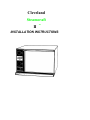
Cleveland
Steamcraft
II
TM
INSTALLATION INSTRUCTIONS
Installation of this unit must be done by qualified plumbing and electrical installation
personnel working to all applicable local and national codes Improper installation of
this product could cause inury or damage.
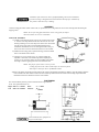
ASSEMBLY
Counter leveling pads with a steamer counter seal (or optional feet) are in a bag within the canon Locate this bag before discarding the
shipping carton
NOTE: The use of leveling pads and steamer counter seat (gasket) on surfaces
other than stainless steel is not recommended
STEPS FOR ASSEMBLY
1) Carefully cut the shipping carton open for easy removal of the steamer. There are four clips mounted to the front two and rear two outer
sheeting mounting screws. These dips were used to lower the steamer
into the carton. They must be removed and discarded pnior to
installation. Reinstall the tour screws and tighten them securely, as
these screws also secure the outer sheet metal cover to the steamer.
2) Install the four leveling pads (or optional four legs) into the threaded
holes on the bottom of the steamer
3) (Omit this next step if optional 4' legs are supplied.) Install the
adjustable counter seal on the bottom edge of the body Begin by
pressing on one end of the sealing stnp at the middle of the bottomfront edge. Continue applying the seal in a clockwise direction.
NOTE: The purpose of the counter seal is to provide
a sealing stnp between the cooker and the surface on which it is placed.
Some surfaces will require the use of additional sealant
4) Remove the plastic dnp trough from the inside of the cooking compartment and install it by sliding it onto the mounting brackets
on the bottom-front of the steamer. Remove the fuse holder caps and fuses from the inside of the cooking compartment and
install them into the fuse holders on the back of the steamer.
POSITIONING
The cooker should be placed in position and leveled left to right and front
to rear. The required clearances are:
Right Side: 6"— 152mm
Left Side: 12"—305mm
Rear:
Vertical:
3' '— 76mm
12 '—
' 305mm
Do not install any other equipment on
top of me Steamcraft II
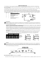
SERVICE CONNECTIONS
Cleveland Range Company equipment is designed and built to comply with applicable standards for manufacturers. Included among
those certification agencies which have approved the safety of the equipment design and construction are: UL. A.G A., NSF, ASME,
CSA, CGA, and others.
Cleveland Range Company equipment is designed and certified for safe operation only when permanently installed in accordance with
local and/or national codes. Many local codes exist, and it is the responsibility of the owner and installer to comply with the
In no event shall Cleveland Range Company assume any liability for consequential damage or injury resulting from installations which
are not in strict compliance with our installation instructions. Specifically, the Cleveland Range Company will not assume any liability
for damage or injury resulting from improper installation of equipment, including, but not limited to. temporary or mobile installations
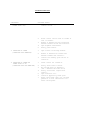
Ref. No.
1
2
3
4
Qty.
1
1
1
2
5
6
7
1
1
2
Description
Ground lug for ground w connection
terminal block for feed wire connection
Feedwire knockout hole—
Fuse holders with 2 amp type KTKR-2
fuses (Part No 06344)
Drawn plumbing
Venting outlets—No connections or restrictions should be made
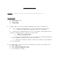
ELECTRICAL
Install in accordance with local codes and/or the National Electric Code ANSI/NFPA No 70-1984 (USA) or the Canadian Electrical Code CSA Standard C22.1 (Canada). A separate fused disconnect switch must be supplied and installed. The steamer must be
eiectncally grounded by the installer.
The electric supply must match the power requirements specified on the steamer's rating label. The copper wiring must be
adequate to carry the required current at the rated voltage.
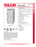
Locate the terminal block cover and "knock-out" plug at the upper left corner of the steamer's back panel. Remove the two screws
securing the terminal block cover and remove the cover. Remove the "knock-out" plug. Feed permanent copper wiring through the
"knock-out." and fasten to the terminal block, in accordance with the wiring diagram affixed to the steamer's back panel. Be sure
to connect the ground wire to the separate ground terminal connecfor (ground lug). Replace the terminal block cover and secure it
with the two screws.
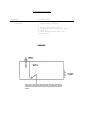
The steamer is— wired for 3-phase delta operation at the facfory. For single phase operation, the installer must change the
Two jumpers on the terminal block to that shown in the accompanying diagram (and on the steamer’s wiring diagram label.)
two jumpers on the terminal block to that shown in the accompanying diagram (and on the steamer's winng diagram label)
1 PHASE
VOLTS
206
220
240
Watts
5000
4202
5000
AMPS
24
19
21
AWG
410
-
-
-
10
10
10
3 PHASE
WATT AMPS
S
5000
14
60 HZ-3 Wire—
4202
5OOO
11
12
AWG
14
14
14
5000
6
14
SUPPLY USE
COPPEB WIRE
ONLY SUITABLE
FOR AT LEAST
75 Degrees C
WATER
A 1/4" * IPS COLD water line is required. DO NOT USE HOT WATER. Minimum water pressure is 35 psi (2 4 kg/cm2), the
maximum water pressure is 60 psi (4.1 kg/cm2), measuring flow pressure, not static pressure Connect the cold water line to the
input side of the line strainer, located on the outside of the steamer's back panel, toward the top-center of the panel Refer to the
service connection drawing for precise location.
RECOMMENDED PLUMBING (furnished by the installer):
Shut-off Valve' The water supply can be shut off at this valve in the event that the steamer, or a plumbing component, requires service
RECOMMENDED PLUMBING (continued):
Stand Pipe: A vertical pipe holding a column of water, topped with a column of air. The air pocket provides a "shock absorber"
effect, to reduce or eliminate the possibility of "water hammering" in the plumbing.
Strainer Removes particles from the water supply which could result in damage to plumbing components.
Pressure Reducing Valve: Required if the incoming water pressure exceeds 60 psi.
Check Valve: Eliminates the possibility of steam generafor water backing up into the water supply plumbing. (This check valve
may be required by local plumbing codes.)
WATER QUALITY REQUIREMENTS
If the purity of the incoming water is good, the generafor, the heating element and the valves should give years of trouble free. efficient
service with a minimum of servicing.
The recommended minimum water quality standards, whether untreated or pretreated, based upon 4 hours of operation before the steamer is
shut off and allowed to drain, are as follows:
• TOTAL DISSOLVED
less than 60 parts per million
•SILICA
less than 13 parts per million
• TOTAL ALKALINITY
less than 20 parts per million
• pH FACFOR
greater than 7.5
Consult a local water treatment specialist for an on-the-premises water analysis and for recommendations concerning steam
generafor feed water treatment (if required), in order to remove or reduce harmful concentrations of minerals. The use of a
poor quality (highly mineralized) water will mean that more frequent servicing of water sensitive components will be
necessary. The fact that a water supply is potable is not proof enough that it will not be detrimental to the water sensitive
components. The steamer should be shut off for 3 minutes every 4 hours, in order to minimize scale build-up.
DRAIN
A 1" N.P.T. fitting is provided. The drain termination must be free venting. Up to two elbows and a maximum of six feet of I* IP.S. pipe may be attached to the termination. However, the piping must have a gravity flow and vent freely to the air. Each steamer
requires its own 1" I.RS. drain extension. Do not interconnect any other drains to this steamer's drain extension.
If these instructions are nor complied with, there will be steam and water leakage past
the compartment door.
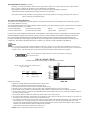
INSTALLATION CHECK
Installer must check out the steamer per the following procedure.
NOTE: The outer shell must be installed in place
before proceeding.
Ref. No.
1
2
3
4
5
Part No.
SB110
43905
40728
19993
20602
Description
Door handle
Timer
Steam— control
On/Off power switch
PIastic dnp trough
CHECK OUT STEPS
1) Empty the cooking chamber of all literature and leave the door open.
2) Make sure the cold water supply line to the generafor is open.
3) Turn on the electrical service to the cooker at the fusible disconnect box.
4) Push the "water on" switch button to the right. The switch is illuminated when it is in the "ON" position.
5) Set the steam control at number ten. Steam should be visible inside the cooking chamber after five minutes of operation.
6) Let the steamer continue to operate for five additional minutes with the steam control set at ten. Steam flow should be visible for
this entire period of operation.
7) Set the steam control to number five. Steam will continue to flow but in a lesser amount.
8) To check the timer and buzzer, turn the timer past 10 minutes to wind it. Then reset the timer at three minutes. At the end of the
three minutes, the buzzer will sound for three seconds and then stop.
9) To completely shut down the steamer, push the "water on" switch button to the left (the light should go out), and turn the steam
control knob to zero. The steam generafor water will automatically drain out. At this time. the generafor flush cycle will be
energized. This system automatically flushes the generafor and drain line to assist in removal of lime deposits. After 3 minutes,
the flush cycle should end and the steamer should shut off completely.
If the cooker has functioned as described, it is ready for use.
Installer: Please complete and mail the Insialler's Checklist.
OPERATION
Operation of the Cleveland Steamcraft II is very easy. Each operator should be familiar with the following procedures to
effectively start operate, and shut down the steamer each day.
Start-up and Preheat
1 Push the "water on" switch to the right. The switch is illuminated when it is in the "on" position.
2 Turn the steam control knob to the number 10 setting. To monitor the start-up, leave the cooking compartment door open.
Steam should begin to appear inside the cooking compartment after approxi mately 5 minutes. Close the door and allow the
steam flow to continue for 5 more minutes to preheat the compartment. To close the door, swing it shut with a quick.
snapping motion.
3 The Steam Cooker is now ready for use. Either proceed with cooking, or turn the steam control knob to "stand-by" at the
number 1 setting.
WARNING:DO NOT PUT YOUR FACE OR HAND(S) INTO THE COOKING COMPARTMENT WHEN
THE STEAMER IS IN OPERATION. STEAM CAN CAUSE SERIOUS BURNS AND BODILY HARM.
Cooking Operation:
1. Check the cooking compartment to ensure it is warm. If it is cool perform the steps for preheating.
2. Place the pan(s) of food into the cooking compartment by sliding the pan(s) into the two slide racks, and secure the door.
Optimum steam heat transfer, and therefore a higher quality food product, is achieved when shallow, perforated, uncovered
pans are used.
3 Activate the steam flow by setting the steam control knob at number 10. The steam supply is variable from 10% at the
number 1 setting, to 100% at the number 10 setting, to supply the precise volume of steam required for cooking. defrosting,
or preheating of fresh or frozen food. For cooking fresh or frozen food, set the steam control knob at number 10. To conserve
energy when cooking only one pan of fresh food. settings lower than number 10 may be successfully used, but the timer
setting may have to be increased.
4. Turn the timer knob past 10 minutes to wind the timer spring, then set the timer at the cooking time required. A buzzer will
sound for 3 seconds at the end of the selected time, then it will stop buzzing automatically.
5. Remove the food from the cooking compartment promptly or it will continue cooking. Steam flow is not shut off by the timer.
Steam flow is only shut off when the steam control knob is set at zero.
6. After the cooking cycle is complete, set the steam control knob to "stand-by" at the number 1 setting to keep the
compartment warm, in preparation for the next cooking cycle.
7 The door may be opened any time during the cooking cycle to inspect season, add, or remove food. but keep hands out of
the cooking compartment to prevent burns. Frequent opening of the door may result in longer cooking times.
Short-Term Holding:
Some foods, after they have been prepared, can be returned to the cooking compartment to be kept hot for short periods of
time (up to 45 minutes) with minimum product change, by turning the steam control knob to the number 1 setting.
Shutdown:
The Steamcraft II must be shut off for three minutes every four hours to automatically drain highly mineralized water from
the steam generator. This is accomplished by pushing the lighted "water on" switch to the left. Turning the steam control knob
to zero does not shut-off the steamer, and therefore does not drain the steam generator.
CARE AND CLEANING
Your Steamcraft II must be cleaned regularly to maintain its fast efficient cooking performance and to minimize down time.
1. The steam generator must be drained every four hours, as well as at the end of the day to remove harmful highly mineralized
water. When steam is produced, the water in the generator is being distilled. During this process, the dissolved minerals that
come into the generator with the water remain in the generator as the water boiIs away as steam. When allowed to
accumulate, the water becomes highly mineralized, which will result in erratic operation, slower cooking times, accelerated
corrosion of the heater element, and ultimately, heater element failure. When the steamer is shut off, an automatic 3 minute
water purge cycle will flush the scale out of the steam generator. Remember, turning the steam control knob to zero only
shuts off the steam supply. The steamer is shut off, and the generator is automatically drained and cleaned, only when the
lighted "water on" switch is pushed to the left.
• With the steamer off, open the cooking compartment door and allow the steamer to cool before cleaning the cooking
compartment and its components.
2. The steamer is equipped with a drain screen in the back of the cooking compartment. The steamer should never be
operated without the screen in place. This screen prevents large food particles from entering and possibly restricting the
drain line. Any restriction of the drain line may cause a slight build-up of back pressure in the compartment, resulting in
steam leaks around the door gasket. It also may adversely affect the convection action of the steam in the compartment,
which is necessary for optimum performance. Pouring USDA approved drain cleaner through the compartment drain once a
week will help to ens ure an open drain.
3. At the end of each day's operation, remove any spilled food from the steamer, then wash the pan slide racks, drain screen,
door gasket, and compartment interior with mild detergent and warm water. Rinse thoroughly with clear water. Rinse water
should drain freely through the compartment drain opening. If it does not the drain must be cleaned before using the
steamer.
4. The pan slide racks are easily removed from the cooking compartment for thorough cleaning, and they are stainless steel,
so they can be washed safely in a mechanical dishwasher.
5. Always leave the compartment door ajar when not in use, to extend gasket life and to prevent the gasket from adhering to
the steamer. Unnecessary compression of the gasket shortens its life.
6. Exterior Care: Allow steamer to cool before washing. Use the same cleaners and cleaning procedures as for other kitchen
surfaces of stainless steel and aluminum. Mild. soapy water, with a clear water rinse, is recommended. Do not allow water to
run into electrical controls. Always turn off equipment power before using water to wash equipment. Do not hose down the
steamer.
7. Once every three months, shut off the cold water supply to the steamer, and clean the water line strainer.
MAINTENANCE
Your Steamcraft II is equipped with an automatic 3 minute water purge system which will flush the highly mineralized water out
of the steam generator when the steamer is shut off. If the steamer's feedwater supply is of average hardness and mineral
content (less than 200 parts per million of total dissolved solids), and the steamer is shut off for three minutes every 4 hours,
this purge system should provide a maintenance free steam generator. However, if your water contains more than 200 parts per
million of total dis solved solids, additional maintenance may be required. In this case. your steamer should be shut off every 2
or 3 hours, depending upon the mineral content of the water. In addition, it may be necessary to periodically have a service
technician remove the steam generator's side panel and clean the scale accumulations on the inside.
The Cleveland Range Company supports a worldwide network of Maintenance and Repair Centers, which are regional
distributors of parts and service. Contact your nearest Maintenance and Repair Center for the name of an authorized service
agency in your area, or for replacement parts, or information regarding the proper maintenance and repair of your equipment. In
order to preserve the various agency safety certifications (UL. A.G.A, CSA, CGA. NSF, ASME/Ntl. Bd, etc.), only factorysupplied replacement parts should be used. The use of other than factory-supplied replacement parts will void the warranty.
INSTALLATION CHECK
Proper operation of the Cleveland Steamcraft II is dependent upon proper installation. After the steamer has been installed, a
few quick checks could save unnecessary service calls.
1. The Steamcraft II requires a cold water connection at the rear of the steamer for proper efficient operation. DO NOT USE
HOT WATER. The cold water feed line should maintain 35 to 60 psi flow pressure, and not experience a pressure drop when
other appliances are used. Pressure in excess of 60 psi must be reduced (with a pressure reducing valve) to 35 to 60 psi.
2. The steamer must be level.
3. The supply voltage must agree with the voltage indicated on the rating label on the back of the steamer, and the voltage
shown on the packing slip. The steamer must be protected with a separate fused disconnect and be property grounded, in
accordance with the national electric code.
4. The termination of the drain extension must vent freely to the air (not plumbed solidly into the floor drain). It must have a
gravity flow, be 1" diameter minimum (IPS) and not exceed 6' in length, with no more than two elbows, before draining. Each
steamer requires its own 1" IPS drain extension. Do not interconnect any other drains to this steamer's drain extension.
CAUTION: IF THESE INSTRUCTIONS ARE NOT COMPLIED WITH. THERE WILL BE STEAM AND WATER LEAKAGE PAST THE
COMPARTMENT DOOR GASKET.
260-SO(R1| 0485
__________________________________________________________________________________
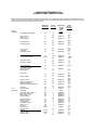
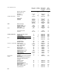
CLEVELAND STEAMCRAFT II®
STEAM COOKER TIMER SETTINGS
Refer to Owner's Manual for operation and pre-heat instructions. Timer settings are approximate due to the difference in food
quality, age, shape, and the degree of "doneness" desired. It is not necessary to add water. Perforated pans are recommended;
*must be cooked in solid pan; *use catch pan for juices.
WEIGHT OR
COUNT/ PAN
NUMBER
OF PAGES
PERFORATED
UNLESS
OTHER WISE
STATED
Frozen
Vegetables:
Asparagus Spears, Medium
5#
Beans, Green or
Wax, 2" Cut
Broccoli Spears
5#
Broccoli Florets
5#
Brussels Sprouts
5#
Carrots, Baby Whole
4#
Carrots, Sliced
or Crinkle
Cauliflower, Florets
4#
Corn, Yellow Whole Kernel
Corn-On-Cob: Cobettes
4#
4#
5#
20 ears
Lima Beans, Baby
5#
Lima Beans, Regular
5#
1
2-3
1
2-3
1
2-3
1
2-3
1
2-3
1
2-3
1
2-3
1
2.3
12x20x2-1/2
1 2-3
1
2-3
1
2-3
1
12x20x2-1/2
12x20x2-1/2
12x20x2-1/3
12x20x2-1/2
12x20x2-1/2
12x20x2-1/2
12x20x2-1/2
12x20x2-1/2
12x20x2-1/2
Corn, Lima Beans,
Green Beans, Carrots
Variety Vegetables:
Italian mix, etc.
Stew Vegetables
Peas, Green
6
16-18
6
16-18
8
16-18
6
12-15
6
12-15
8
15-17
7-8
15-16
6
15-16
12x20x2-1/2
5
815-16
16-18
5
12
8
12x20x2-1/2
2-3
14
50
1 2-3
12x20x2-1/2
6-8 17.18
4#
12x20x2-1/2
12x20x2-1/2
12x20x1
4
16-17
6
12-14
6
15-17
18-20
30-35
15-18
30-33
17
24-26
5
10-12
12-13
6
Potatoes, White
10#
Potatoes, Sweet
5#
Spinach, Chopped, Leaf
(Partially Defrosted)
Spinach (Completely Defrosted)
6#
Succotash
Zucchini, Sliced
6#
5#
1
2-3
1
2-3
1
2-3
1
2-3
1
2-3
1
2-3
1
2-3
1
2
Artichokes
25
1
12x20x1
22
Asparagus. Spears, Medium
Beans, Green, 2" Cut
Beans, Wax, 2" Cut
Broccoli Spears
5#
5#
5#
5#
1
1
1
1
2-3
2
1
1
1
1
2
1
12x20x2-1/2
12x20x2-1/2
12x20x2-1/2
12x20x2-1/2
5
6
6
6
14-16
8
6-8
11
7-8
7
13
10-12
5#
5#
Fresh
Vegetables:
TIMER
SETTING
(MINUTES)
Brussels Sprouts
Cabbage. Cut 1/8
Carrots, Sliced
Cauliflower. Florets
Cel ery, Cut 1"
Diagonal
Corn-On-Cob
6#
5#
5#
9#
6#
5#
18#
18 ears
Potatoes. White
(Russet)
Potatoes, Idaho
Potatoes. Sweet
12x20x2-1/2
12x20x2-1/2
12x20x2-1/2
12x20x2-1/2
12x20x2-1/2
12x20x2-1/2
12x20x2-1/2
12x20x2-1/2
12x20x2-1/2
12x20x2-1/2
12x20x2-1/2
12x20x1
2-3
10-13#
10-13#
10#
3
3
1
2-3
16-18
12x20x2-1/2
12x20x2-1/2
12x20x2-1/2
55
50
40
45
Fresh Vegetables (cont'd)
WEIGHT OR
COUNT/PAN
NUMBER
OF PANS
2#
1
2-3
Squash, Acom, Cut
into Halves
Zucchini, Sliced
10 halves
5#
Drained
1-#10 can
1
1
2-3
1
1-#10 can
2-#1Ocans
1-#10 can
2-#l10 cans
2-#l0cans
4-#l0 cans
Blanch for Peeling:
Grapefruit, whole
Oranges, Lemons, Limes
Pineapple for cutting
Prunes, dried
Soft Cooked, in Shell
Coddled, in Shell
Hard Cooked, in Shell
Scrambled
Spinach, Cut & Cleaned
CANNED VEGETABLES:
Beans, Baked
or Refried:
Uncovered
FRUIT:
EGGS:
FROZEN CASSEROLES:
MEAT:
Examples: Beef Stew, Lasagna
Cabbage Rolls,
Stuffed Peppers,
Tamales, Enchiladas
12x20x2-1/2
12x20x1
12x20x2-1/2*
25
8
12-15
6
1
1
2
2
1
1
12x20x2-1/2*
12x10x4 *
12x20x2-1/2*
12x10x4 *
12x20x2-1/2*
12x20x4 *
9
22
10-12
25-27
10-12
40-55
10-12
2-3 dz.
3-4 whole
4#
4 dz.
1
1
1
1
1
12x20x1
12x20x1
12x20x1
12x20x2-1/2*
12x20x1
3
3
4
12-15
4
4 dz.
4 dz.
5 Ib.-5 dz.
1
1
1
12x20x1
12x20x1
12x20x2-1/2*
6
14
10
5#
1
2
1
2-3
12x20x2-1/2*
12x20x2-1/2*
12x20x2-1/2*
12x20x2-1/2*
30-35
35-45
35-40
50-60
10#
3
5-6
10#
1
12x20x2-1/2*
33
Beef Cubes, as purchased
Meat Loaf, 4 Loaves, 4 lb. ea.
Hotdogs/Weiners,
Spareribs 3 & down
10#
16#
10#
10#
1
1
1
4
12x20x2-1/2*
12x20x2-1/2*
12x20x1
12x20x1*
40-45
40-42
3
40
15#
6-7# each
12-16#
1#
1
1
1
1
12x20x2-1/2**
12x20x1**
12x20x2-1/2**
12x20x1 **
20
90
90
2 hrs.
4#
6#
3#
4#
4 count
1
1
1
1
1
12x20x1**
12x20x1**
12x20x1**
12x20x1**
12x20x1**
5
4-6
4
8
10-12
20 count
3 dz.
1
1
12x20x1**
12x20x1**
10
3
10#
1
12x20x1**
6
1
12x20x2-1/2
10-12
2#
4#
2#
1
1
1
12x20x2-1/2
12x20x2-1/2
12x20x2-1/2
12-15
12-15
12-15
2#
2#
3#
1
1
1
12x20x2-1/2
12x20x2-1/2*
12x20x2-1/2*
18-20
22
28
Chicken, pieces
Frozen Turkey Breast (2)
Whole Turkey, Thawed
Turkey, Frozen
FISH:**
Shrimp, 10 ct/lb.
King Crab Legs, Frozen
Fresh Scallops
Fresh Scrod, 5 oz. Portions
Lobster, Live, 1#
Lobster Tail, 8 oz. Frozen,
Thawed, Butterfly
Clams, Cherrystone
Salmon Steak, 8 oz. Fresh
or Frozen
Oumplings, spoon on top of pre-heated
Beef Stew, etc.
Pasta: (Use nested pans, add water to
cover, stir at least once during
steaming.)
Noodles. 1/2" wide
Macaroni-Elbow
Spaghetti-Vermicelli and
Spaghetti-Regular
Potatoes (Use nested pan, add
water to cover)
Rice, Long Grain, add 4
cups water per Ib.
0585
TIMER
SETTING
(MINUTES)
Beef, Ground Chuck
POULTRY:** (WITH BONE)
DEHYDRATED
FOODS:
PERFORATED
PAN UNLESS
OTHERWISE
STATED
12x20x2-1/2
Data Sheet— 261-EF ("
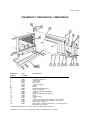
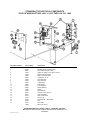
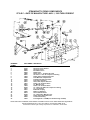
STEAMCRAFT II MECHANICAL COMPONENTS
REFERENCE
NUMBER
PART
NUMBER
DESCRIPTION
1
2
3
4
5
6
7
19177
66651
07138
04172
44039
19578
44037
58110
44040
19577
40589
02624
40588
58198
41423
62201
41101
41102
20602
20601
Sealing Screw (4 required)
Gasket Retainer Plate
Gasket. Door
Door Casting
Door Cover
Lower Door Spring
Latch
Handle
Handle Mounting Hardware
Upper Door Spring
Latch Pin & Retainer (2 required)
Bushing
Hinge Pin & Retainer (2 required)
Hinge
Slide Assembly
S trike
Drain Screen (used on units built before July 31,1982)
Drain Screen (used on units built after Aug. 1,1982)
Drip Trough — Plastic
Dnp Trough — Aluminum (Not Shown — Used only on units
built before Aug. 20.1979)
89
10
11
12
13
14
15
16
17
18
18A
CLEVELAND RANGE, INC. 1333 EAST 179th ST.. CLEVELAND, OHO 44110
Manufacturer reserves right of design improvement or modification, as warranted
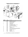
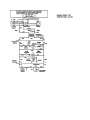
STEAMCRAFT II ELECTRICAL COMPONENTS
DATE OF MANUFACTURE: JAN. 31, 1979 THRU JULY 31, 1982
REFERENCE NUMBER
1
2
3
4
5
6
7
8
9
10
11
12
13
14
15
16
17
18
19
20
21
PART NUMBER
07142
08226
08225
19981
19980
40728
20533
43905
43956
16609
40462
62459
02626
41350
43908
03518
20477
23195
12330
43909
06340
06341
14908
DESCRIPTION
Heater Gasket
208-220V Heater. Immersion 5KW
240V Heater. Immersion 5KW
"Water On" Switch (on-off power switch)
Heater Protection Switch
Steam Control With Knob
Transformer. 75 VA
Timer With Knob
Panel Assembly
1" Brass Plug
Probe, Single
Probe Extension
Adaptor Bushing
Buzzer
Terminal Block
Contactor. 4 Pole. 30 Amp
Timer. Solid State
Water Level Control
Ground Lug
Terminal Block — Main Power
Fuse
Fuse Holder
Label (not shown)
CLEVELAND RANGE. MC. 1333 EAST 179th ST.. CLEVELAND, OHIO 44110
Manufacturer reserves right of design improvement or modification, as
warranted.
LITHO IN U.S-A 0982
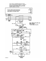
STEAMCRAFT II ELECTRICAL COMPONENTS DATE OF
MANUFACTURE: AUG. 1, 1982 THRU PRESENT
REFERENCE
NUMBER
1
2
3
4
5
6
7
8
9
10
11
12
13
14
15
16
17
18
19
20
PART
NUMBER
08228
08229
08231
07128
19993
40728
20533
43905
43956
44049
14908
20477
20478
41350
03518
43908
23195
03515
23198
16673
06344
06343
12330
43909
DESCRIPTION
208V Heater. Immersion. 5KW
220-240V Heater. Immersion. 5KW
480V Heater. Immersion. 5KW
Heater Gasket. 3" Square
O n-Off Power Switch
Steam Control With Knob
Transformer, 75VA
Timer With Knob
Panel Assembly (after 9/13/83)
Panel Assembly (from 8/1/82 through 9/12/83)
Label, Control Panel (not shown)
Timer, Solid State. 3 Second (Buzzer)
Timer, Solid State. 3 Minute (Water Flush)
Buzzer
Contactor, 4 Pole. 30 AMP
Terminal Block
Water Level Control Board (from 8/1/82 through 9/12/83)
Low Water Cut-Off S/S Board (from 8/1/82 through 9/12/83)
Water Control Board (after 9/13/83)
Probe. Dual
Fuse, 2 AMP. Type KTKR-2
Fuse Holder
Ground Lug
Terminal Block -Main Power
CLEVELAND RANGE, INC., 1333 EAST 179th ST., CLEVELAND, OHIO 44110
Manufacturer reserves nght of design improvement or modification, as warranted LITHO IN U.S.A.
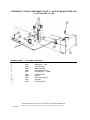
STEAMCRAFT II PIPING COMPONENTS STYLE A — DATE OF MANUFACTURE: JAN.
31, 1979 thru DEC. 10, 1980
REFERENCE NUMBER
PART NUMBER DESCRIPTION
1
2
43657
22216
Generator with Insulation
Safety Valve — 1 PSI
3
06188
Tee Tube Fitting
4
03350
Water Conditioner
5
22218
Valve. Water Solenoid
6
15463
Flow Regulator — 1/4 GPM
7
20245
Tee Male Branch
8
19880
Strainer
9
22217
Valve. Drain Solenoid
10
16478
Drain Pipe
11
14497
Condenser Nozzle
CLEVELAND RANGE. INC. 1333 EAST 179th ST., CLEVELAND. OHIO 44110
Manufacturer reserves right of design improvement or modification, as warranted
LITHO IN U.S A
Data Sheet 261 EK(
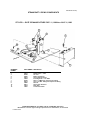
STEAMCRAFT II PIPING COMPONENTS
STYLE B — DATE OF MANUFACTURE: DEC. 11, 1980 thru JULY 31, 1982
REFERENCE
NUMBER
1
2
3
4
5
6
7
8
9
10
11
12
PART NUMBER DESCRIPTION
43657
22216
20199
03350
22218
15463
06196
06214
19880
22217
16478
14497
Generator with Insulation
Safety Valve — 1 PSI
1/4" Tee
Water Conditioner
Valve. Water Solenoid
Flow Regulator — 1/4 GPM
3/8Tee x '/4 MPT. 90'' Compression Fitting
1/4Tee x % MPT. 90degree Compression Pitting
Strainer
Valve. Drain Solenoid
Drain Pipe
Condenser Nozzle
CLEVELAND RANGE, INC. 1333 EAST 179th ST, CLEVELAND, OHIO 44110
Manufacturer reserves right of design improvement or modification, as warranted.
LITHO IN U.S.A.
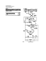
STEAMCRAFT II PIPING COMPONENTS
STYLE C—DATE OF MANUFACTURE: AUG. 1, 1982 THRU PRESENT
REFERENCE
NUMBER
1
2
3
4
5
6
7
8
9
10
11
12
13
14
15
16
17
18
19
20
21
22
23
24
PART NUMBER DESCRIPTION
43658
07143
66586
05263
22222
14480
06227
14553
16482
03395
16481
22221
14551
20247
14554
06192
19870
03641
16480
22218
06188
14552
02549
15463
Generator. With Insulation and Cover .
Generator Cover Gasket
Generator Cover
Ell. Radiator Union
Safety Valve
Nipple. 3/8" x 1 Threaded One End
1/4" Tube x 1 FPT. 90* Compression Pitting
Nozzle. Spray Compartment Drain
Drain Manifold. Compartment
Flexible Drain Pipe Connector
Drain Pipe, Generator
Valve, Drain, Special Solenoid
Nozzle, Jet. Generator Drain
1/2- Mate Run Tee
Nozzle, Jet. Generator Drain
1/4" Tube x 1/8" MPT, 90° Compression Fitting
1/4" Line Strainer
Bulkhead Coupling
Water Line Manifold
Valve. Water Solenoid
1/4" Tube Fitting, Male Run Tee
Nozzle, Spray, Generator Drain
Condenser Bushing
Flow Regulator. 1/4 GPM (from 8/1/82 through 11/30/83)
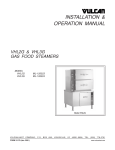
NOTE: FOR SAFETY PURPOSES, DRAM SCREEN COVER MUST BE IN PLACE WHEN OPERATING EQUIPMENT.
CLEVELAND RANGE, INC, 1333 EAST 179th ST.. CLEVELAND, OHIO 44110
Manufacturer reserves right of design improvement or modification, as warranted
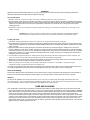
STEAMCRAFT II
208V & 220/240V (ONLY)
WIRING DIAGRAM
CLEVELAND RANGE DESCALING KIT
INSTRUCTIONS FOR CHEMICALLY DESCALING A
STEAMCRAFT II EQUIPPED WITH A DUAL PROBE
For a thorough understanding of proper procedures and precautions, read these instructions completely before proceeding.
IMPORTANT
Before using this acid descaling product, read the safety precautions and first aid' instructions found
on the container label.
Steamcraft IIIsteamers produced after August 1, 1982 are equipped with removable side panels on the outside wall of the
steam generator for ease of cleaning in addition to chemically descaling. Peel off the tape securing the generator side wall
insulation, then swing the insulation upward to access the generator removable side panel. Remove the lockwashers and nuts
securing the removable panel, then remove the panel and gasket. Using a scoop, or a tablespoon, or by hand, remove scale
build-up from the generator. Install a new gasket, then replace the side panel, securing it with the lockwashers and nuts to 30
inch-pounds torque. DO HOT OVER-TORQUE TEE NUTS, as the studs will break off. There is never any pressure in the
generator, and therefore, the nuts do not require heavy torquing to create a water-tight seal.
PREPARATION:
The plastic jar of descaling compound contains 10 pounds of sulfamic acid as a base chemical, plus a specially formulated
blend of a corrosion inhibitor, wetting agent, and color-change pH indicator to improve cleaning effectiveness in removing
hard water scales and other deposits. This product is water soluble and its solution performs most efficiently when maintained
at temperatures of 150 - 160°F (65 - 71°C). Also included is an 8 ounce poly-bag of soda ash (sodium carbonate) neutralizer.
Effective descaling and neutralizing of the Steamcraft II steam generator is generally accomplished by using 1 pound of
descaling powder (1/10 of the plastic Jar's contents) and 1 ounce of neutralizer (1/8 of the poly-bag's contents).
WARNING: Steam and hot water may cause serious
injury and bodily harm when it is accidentally or carelessly
released. Improper handling of acid could cause serious,
permanent injury. Therefore, service of the steam
generator should only be performed by 'trained and experienced personnel, thoroughly fami
liar with servicing generators.
Mix approximately 1 ounce (1/8 of the poly-bag's contents)
of soda ash neutralizer in 1 cup of water. Bicarbonate of
Soda or baking soda are suitable alternative neutralizers.
Keep this solution nearby to be used to neutralize acid that
may be accidentally spilled.
Turn off electrical power to the steamer at the main fused disconnect power switch. Remove the six screws (3 left & 3 right)
along the lower left and right edges of the once piece outer sheeting. Lift the outer sheeting straight up and off the steamer.
GENERATOR DESCALING
Locate the generator probe (top rear of generator). Remove the low water probe wire (red) and water
level probe wire (grey) from the probe terminals. Isolate probe wires to prevent inadvertent grounding
until required for reconnection. Remove the probe from the top of the generator.
Inspect the generator and probe to determine the severity of mineral scale build-up. If build-up is
considerable, side panel removal may be required. Using a fine grid emory paper remove any scale
build-up on the probe extensions before reinstallation.
Pour the premeasured one pound of descaler into the generator via the probe coupling. Install the probe
in generator and reconnect only the red probe wire.
Energize the electric power supply to unit and push power "ON" switch. The generator is now filling with
water. Open the compartment door and watch the steam port for water flow. When water starts to enter
compartment, reconnect grey generator probe wire. Water should stop flowing.
Turn the heat control switch to "10", setting. Once again view the compartment steam port for water
flow, approximately 3 minutes. Turn the heat control switch to "0" when steam or water starts to gurgle
from port.
Let the solution stand for several hours. The descaling process can range in time from a few hours, to
overnight, depending upon the severity of the scale.
When the descaling process is complete, push the steamer's power switch to the "OFF" position to drain
the generator of descaling solution.
GENERATOR FLUSH
Remove the two probe wires from the probe and isolate them. Remove probe from generator and
examine the generator for any scale residue. Connect the grey probe wire to the "ground" connection on
the top of the generator. Push the power on switch to the "ON" position. Pour the neutralizer solution
into the generator probe coupling. Replace the generator probe and tighten securely, make sure that the
probe terminals .are parallel with the rear wall of the unit. Remove grey wire from ground terminal isolate
wire until required.
Generator is now filling with water and neutralizing solution. Observe the compartment steam port for
water flow, approximately 45 seconds, and reconnect the grey wire to probe terminal. Allow solution to
stand in generator for 5 minutes. Push the power switch to the off position to drain the generator.
Disconnect the grey wire from the probe and isolate it once more. Energize the power on switch and
observe the compartment for water flow. De-energize the power switch when water appears in the
compartment and allow unit to complete the purge cycle. Turn off main electrical supply to unit.
Reconnect red and grey probe wires to the proper terminals with their lockwashers and nuts. Reenergize the main fused power connection.
STEAMER TESTING
Test the steamer for proper operation. Push the power switch to the "ON" position. The red light will illuminate
when the steamer is on. Turn the steam control knob to number "10". Leave the cooking compartment door open.
Steam should begin to appear inside the cooking compartment after approximately 5 minutes . Inspect plumbing for
leaks.
If the steamer is operational, push the power switch to the "OFF" position, then turn the steam control knob to zero.
Finally, reinstall the outer sheeting, securing it with the six screws.
TROUBLESHOOTING CHART
COMPLAINTS
1. NO OPERATION
(POWER LIGHT OUT)
POSSIBLE CAUSES
1.
No power being supplied to
terminal block.
2.
4.
Blown control circuit fuse in holder at
rear of steamer.
Broken or burned off wire connection
between terminal block and contactor.
Open stepdown transformer.
5.
Faulty power switch.
1.
Open circuit in heating element.
2.
Broken or burned wire connections
between element and contactor.
Contacts not making good contact in
3.
3. PRODUCING NO STEAM
(CONTACTOR DOES ENERGIZE)
3.
contactor.
4. PRODUCING NO STEAM BUT
POWER LIGHT IS ON
(CONTACTOR DOES NOT ENERGIZE)
1.
Steam control not turned on.
2.
3.
Faulty steam control switch.
Not enough water in generator.
(See : Generator Will Not Fill)
Faulty solid state liquid level
control.
Open contactor coil.
Contactor physically stuck open.
Drain valve stuck open, not allowing
generator to fill and activate low
water cutoff probe.
4.
5.
6.
7.
TROUBLESHOOTING CHART
COMPLAINT 5. GENERATOR WILL NOT FILL WITH WATER WHEN POWER SWITCH IS ON
POSSIBLE CAUSES
I.
If power light is off :
A.
Power switch
B.
Power supply
C.
Control fuse
II.
If power light is on and no voltage is measured across the fill solenoid coil :
A.
If no voltage is measured across LI & L2 on the level control board :
1.
Broken wire connection from power switch to level board.
B.
If 120 volts is measured across LI & L2 on the level control board and no
voltage is measured from L2 to WF on the level board :
1.
Faulty level control board.
2.
Check for grounded probe.
C.
If 120 volts is measured across LI & L2 on the level control board and 120
volts is measured from L2 to WF on the level board.
1.
Broken wire connection from WF to water fill solenoid or from solenoid
coil to transformer.
III. If power light is on and 120 volts is measured across the fill solenoid coil.
A.
Water supply off.
B.
Fill solenoid clogged with scale.
C.
Fill solenoid mechanically stuck.
D.
Fill solenoid coil open.
TROUBLESHOOTING CHART
COMPLAINT
6.
GENERATOR OVERFILLS & TEE POWER SWITCH IS ON
(WATER RUNS OVER INTO THE COOKING COMPARTMENT FROM STEAM
DISCHARGE)
POSSIBLE CAUSES
I.
If no voltage is measured across either the purge solenoid
coil or the fill solenoid coil.
A.
Foreign material or scale could be physically keeping
the plunger from seating, thus allowing water to
continually enter the generator through one of the
solenoids.
II.
If 120 volts is measured across the purge solenoid
coil.
A.
Purge timer contacts are stuck closed.
III. If 120 volts is measured across the fill solenoid coil.
A.
Faulty liquid level control board.
B.
Faulty probe.
C.
Broken or poor ground connection to common terminal
on levelcontrol board.
D.
Broken or poor probe wire connection from level board
to the probe.
E.
Scale buildup on probe.
F.
Heavy scale buildup in
generator.
TROUBLESHOOTING CHART
COMPLAINTS
POSSIBLE CAUSES
7. WATER OVERFLOWS INTO
COOKING CHAMBER THROUGH
DRAIN AND/OR STEAM
DISCHARGE
1. Drain not open to atmosphere.
2. Drain line not minimum 1 inch size.
3. Drain manifold or fittings clogged with
buildup or spilled food buildup.
Note : This condition is caused when the
condenser water or purge water
cannot exit through the drain
quickly enough.
8. LOW STEAM OUTPUT
1. Element partially burned out.
Note : Resistance for each of 3 paths
of element should be approximately :
31 ohms at 208 volts
36 ohms at 240 volts
48 ohms at 480 volts
2. Steam control switch set too low.
3. Excessive scale buildup on element
reducing heat transfer to generator
water.
4. Supply voltage not correct or too low.
9. EXCESSIVE ELEMENT FAILURE
1. Element tubes not split open or
overheated.
a. Improper supply voltage.
b. High voltage spikes from power
2. Element tubes split open or bright red
from overheating.
* THIS CONDITION CAN ONLY BE CAUSED
WHEN THE ELEMENT IS ENERGIZED WITHOUT
BEING IMMERSED IN WATER.
a. Check condition of probe - make
sure electrodes show no resistance
to ground. (Probe body should be
constructed of white teflon
including threads). If probe has
brass fitting or shows any
deformity, replace it.
TROUBLESHOOTING CHART
COMPLAINTS
POSSIBLE CAUSES
9. EXCESSIVE ELEMENT FAILURE
(Continued)
b. Excessive buildup of scale on
element and in generator.
c. Faulty level control board.
d. Shorted wiring to ground from probe
connections.
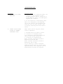
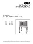
e. Probe chamber scaled shut. (See
drawing below)
If this area becomes blocked from scale buildup, false water
levels can be sensed by the electrodes. The generator must be
delimed and cleaned. This is a fairly frequent cause of element
failure.
TROUBLESHOOTING CHART
COMPLAINTS
10. CONTACTOR NOISY WHEN
ENERGIZED
POSSIBLE CAUSES
1. If the contactor is buzzing loudly, the
armature in the contactor is not
properly seated. This is usually do to
warped Bakelite parts, or broken parts.
Replace the contactor.
2. If the contactor is chattering loudly
when it is energized or de-energized,
one of the controls that energizes the
contactor coil has poor contact. This
is usually caused by the steam control
switch.
11. CONTROL CIRCUIT PUSES
ON BACK OF STEAMER
CONTINUALLY BLOW
These fuses control only the control
circuit components.
1. Shorted wiring in control circuit.
2. Contactor coil breaking down.
Coil resistance should be between 100
and 125 ohms (Gould Contactor).
3. Solenoid coil breaking down.
Water solenoid resistance should be
between 575 and 640 ohms.
Drain solenoid resistance should be
between 45 and 55 ohms.
If you find any of these components
measuring resistances out of the ranges
specified above, that component coil is
breaking down and must be replaced.
TROUBLESHOOTING CHART
COMPLAINTS
12. POWER SUPPLY CIRCUIT
BREAKER OR FUSES
CONTINUALLY BLOW
POSSIBLE CAUSES
1. Undersized breaker or fuses.
(See installation section for ratings.)
2. Wrong voltage supply to steamer.
(A 208 volt steamer supplied with 230
volts will draw approximately 33%
excess amperage over the rated
nameplate amps).
3. Shorted wiring or connections at
terminal block or contactor.
4. Faulty beating element.
5. Carbon buildup across contactor
contacts or heating element terminals.
AS A RULE OF THUMB, IF A CIRCUIT BREAKER
TRIPS IMMEDIATELY, THERE IS A SHORT
CIRCUIT. IF IT STAYS ON A WHILE AND TEEN
TRIPS IT IS OVERLOADED OR THE BREAKER OR
FUSE IS WEAK.
13. EXCESSIVE PROBLEM WITH
BURNED OFF WIRE CONNECTIONS
1. Factory wire connections are made very
carefully. During the life of any
machine, wire connections can bum off
due to loose connections, or faulty
controls.
WHEN A CONNECTION BURNS OFF, BOTH THE
WIRE AND THE TERMINAL CONNECTORS SHOULD
BE REPLACED. NEW TERMINALS ON BURNED
WIRE WILL JUST BURN OFF AGAIN.
TROUBLESHOOTING CHART
COMPLAINTS
14. WATER CONTINUALLY RUNS OUT
OF THE DRAIN LINE
POSSIBLE CAUSES
1. Power switch is off for over 5 minutes.
a. Fill solenoid leaking through its
seat.
b. Purge solenoid leaking through its
seat.
c. Condenser solenoid leaking through
its seat.
d. Purge timer contacts stuck closed.
2. Power switch is on & heat switch is
off.
a. Condenser solenoid is leaking
through its seat.
b. Drain solenoid is leaking through
its seat.
3. Power switch is on & steam switch is
on.
a. Normal operation - condenser water
is fed into drain line to condense
steam, so only condensate exits the
drain line.
15. STEAM LEAKS OUT OF COOKING
COMPARTMENT DOOR
1. The Steamcraft II is a pressureless
free venting steamer. Steam coming out
the door almost always indicates a
restricted or partially restricted
drain line. A condenser solenoid that
is not operating can also cause this
problem. The cold water in the drain,
condensing the steam* causes a natural
vacuum which helps draw the steam down
the drain.
2. A broken or badly swollen door gasket.
3. Food buildup on gasket keeping the
gasket from sealing properly.
TROUBLESHOOTING CHART
COMPLAINTS
POSSIBLE CAUSES
16. TIMER WILL NOT TIME OUT
1. Faulty timer - replace.
17. TIMER TIMES OUT BUT BUZZER
1. No voltage to buzzer.
WILL NOT SOUND
a. Timer contacts.
b. Solid State Delay Timer.
2. 120 volts to buzzer.
a. Inoperative buzzer - replace.
18. BUZZER WILL NOT SHUT OFF
1. Faulty solid state buzzer timer.