1
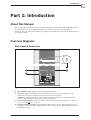
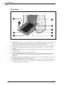
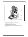
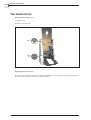
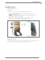
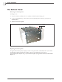
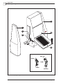
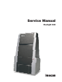
Service Manual
Flextight 848
0-2
© 2002 Imacon A/S. All rights reserved.
Imacon Flextight 848 Service Manual, revision 1.0
The information in this manual is furnished for informational use only, is subject to change without notice,
and should not be construed as a commitment by Imacon A/S.
Imacon A/S assumes no responsibility or liability for any errors or inaccuracies that may appear in this
manual.
Imacon A/S assumes no responsibility or liability for loss or damage incurred during or as a result of
using Imacon software or products.
Imacon, FlexColor and Flextight are trademarks of Imacon A/S. Adobe and Adobe Photoshop are
trademarks of Adobe Systems, Inc. Macintosh, Mac OS and ColorSync are registered trademarks of Apple
Computer, Inc.
Printed in Denmark.
Service Manual - Flextight 848
Table Of Contents
Table Of Contents
Part 1: Introduction
Part 6: The Drive System
About this Manual . . . . . . . . . . . . . . . . . . . 1-1
Overview Diagrams . . . . . . . . . . . . . . . . . . 1-1
Back Panel & Connectors . . . . . . . . . . . . 1-1
Front Panel . . . . . . . . . . . . . . . . . . . . . . 1-2
Cut-Away View . . . . . . . . . . . . . . . . . . . . 1-3
General . . . . . . . . . . . . . . . . . . . . . .
Replacing the Original Loader . . . . .
Replacing the Drum Motor . . . . . . . .
Replacing the Drum Position Sensor
Replacing the Drive Belts. . . . . . . . .
Part 2: Problem Diagnosis
Striping in Images . . . . . . . . . . . . . . . . . . . 2-1
Striping in Reflectives Only . . . . . . . . . . . 2-1
Striping in Dark Areas Only (or Light Areas for
Negatives). . . . . . . . . . . . . . . . . . . . . . . 2-1
General Striping Problems. . . . . . . . . . . . 2-1
Bands or Scattered Pixels . . . . . . . . . . . . . 2-1
No Image. . . . . . . . . . . . . . . . . . . . . . . . . . 2-2
Drive Problems . . . . . . . . . . . . . . . . . . . . . 2-2
Lost Originals. . . . . . . . . . . . . . . . . . . . . 2-2
If the Drum Motor Does Not Turn Off . . . . 2-2
If the Originals Are Not Loading Correctly . 2-2
Noise When Refocusing . . . . . . . . . . . . . 2-3
Focus Problems . . . . . . . . . . . . . . . . . . . . . 2-3
.
.
.
.
.
.
.
.
.
.
.
.
.
.
.
.
.
.
.
.
.
.
.
.
.
.
.
.
.
.
.
.
.
.
.
.
.
.
.
.
.
.
.
.
.
.
.
.
.
.
.
.
.
.
.
.
.
.
.
.
.
.
.
.
.
.
.
.
.
.
.
.
.
.
.
.
.
.
.
.
.
.
.
.
.
.
.
.
.
.
.
.
.
.
.
3-1
3-1
3-2
3-3
3-4
Part 4: Light Tubes
General . . . . . . . . . . . . . . . . . . . . . . . . . . . 4-1
Replacing the Light Tubes . . . . . . . . . . . . . 4-3
Replacing a Lamp Driver Board . . . . . . . . . 4-4
Service Manual - Flextight 848
.
.
.
.
.
.
.
.
.
.
.
.
.
.
.
.
.
.
.
.
.
.
.
.
.
6-1
6-1
6-3
6-4
6-5
.
.
.
.
.
.
.
.
.
.
.
.
.
.
.
.
.
.
.
.
7-1
7-1
7-3
7-4
Part 7: The Light Table
General . . . . . . . . . . . . . . . . . . . .
Replacing the Light Board . . . . . .
Adjusting the Light Table Damper.
Replacing the Light Table Damper
.
.
.
.
.
.
.
.
Part 8: Main Board
Saving Current Settings . . . . . . . . . . . . . . . 8-1
Main Board LED's. . . . . . . . . . . . . . . . . . . . 8-1
Replacing the Main Board . . . . . . . . . . . . . 8-2
General . . . . . . . . . . . . . . . . . . . . . . . . . . . 9-1
Saving/Loading Calibration Settings . . . . . . 9-2
Saving settings to a File . . . . . . . . . . . . . 9-2
Loading Settings from a File . . . . . . . . . . 9-2
Loading Factory Settings . . . . . . . . . . . . . 9-3
Focus Calibration. . . . . . . . . . . . . . . . . . . . 9-4
White Calibration for Reflectives . . . . . . . . 9-5
CCD Calibration . . . . . . . . . . . . . . . . . . . . . 9-7
Drum Position Calibration . . . . . . . . . . . . . 9-8
Advanced Focus and Position Calibration . . 9-9
Opening the Motor Positions Window . . . . 9-9
Part 10: Spare Parts
Spare parts for Flextight 848 . . . . . . . . . . 10-1
Part 5: Sensor and Optics
Testing the Sensor and Optics . . .
Cleaning the Sensor and Optics . .
Lubricating the Spindles . . . . . . .
Replacing the CCD Sensor Board .
Replacing the Optics . . . . . . . . . .
.
.
.
.
.
Part 9: Calibration
Part 3: Covers and Panels
General . . . . . . . .
The Front Panel . .
The Inside Cover .
The Side Covers. .
The Bottom Panel
.
.
.
.
.
.
.
.
.
.
.
.
.
.
.
.
.
.
.
.
.
.
.
.
.
.
.
.
.
.
5-1
5-2
5-4
5-5
5-8
0-3
0-4
Table Of Contents
Service Manual - Flextight 848
Introduction
About this Manual
Part 1: Introduction
About this Manual
This manual describes how to perform basic maintenance on the Imacon Flextight 848 scanner.
It is intended for use by trained technicians only. It must not be given to customers or
end-users. The procedures described here require a reasonable level of technical skill and access
to the proper tools.
Overview Diagrams
Back Panel & Connectors
5
C
B
D
A
Figure 1-1: Back panel features of Flextight 848
A Power Cable Socket: plug the power cable into this socket.
B SCSI Port: plug a SCSI cable here and connect it to the previous SCSI-device in your
SCSI-chain or to your computer if no other devices are connected.
NOTE! The scanner must always be connected as the last device in a SCSI-chain as the
scanner's SCSI interface has an internal active terminator.
C SCSI Address Selector: assign an address number using the + and - buttons. Use only 1, 2,
3, 4, 5, or 6. Do not use 0, 7, 8, or 9.
D FireWire Interface Sockets: plug a FireWire cable (max. 6 m) here and connect it to your
computer. You can use the second plug to connect another device (hard disk, printer etc.) to
the FireWire chain.
Service Manual - Flextight 848
1-1
1-2
Introduction
Overview Diagrams
Front Panel
A
D
E
F
B
G
C
H
Figure 1-2: Front panel features of Flextight 848
A Feed Table: must be in lower position for normal scanning. When scanner is not in use, you
can turn it to upright position flushing with the scanner front to protect it from dust etc.
Adjust to horizontal position when using the 35 mm slide mount holder.
B Light Table: for viewing originals. The grid helps you to align your transparent originals.
C Transparency Holder Guide: all transparency holders fit between two rails to keep them
straight.
D Original Holder Clasp: all original holders slide into a slot here and are held in place by a
magnetic clasp.
E Power Switch: press here to switch the unit on/off.
F Power Indicator (Green): Remains lit when ready to scan. Flashes when first installed to
indicate that firmware must be loaded (it will be loaded automatically when you run
FlexColor).
G Motor Drive Indicator (Yellow): lights when the scanner is repositioning the optics to scan
in a new format or when drum is repositioning.
H Scan Indicator (Red): lights when scanning. Do not touch the scanner while this indicator is
lit. If the light is flashing when not scanning, then an error has occurred - please contact
your Flextight dealer for assistance.
Service Manual - Flextight 848
Introduction
Overview Diagrams
Cut-Away View
A
B
C
FLEX
TIG
HT
OR
IGIN
AL
D
HO
LD
ER
PATE
NT
PE
ND
ING
E
F
G
Figure 1-3: Cut-away view of Flextight 848
A CCD Housing: this movable platform contains the CCD sensor.
B Positioning Lead Screws: for positioning of the CCD housing and optics housing for the
appropriate resolution and original size.
C Optics Housing: holds the optics (lens). Focuses the image of the original on the CCD.
D Upper Light Source: illuminates reflective originals.
E Lower Light Source: illuminates transparent originals.
F Drum: rotates the original into the scanner and steps it past the CCD line of focus.
G Original Holder: a transparency holder is shown mounted and with the top layer held
open.
Service Manual - Flextight 848
1-3
1-4
Introduction
Service Manual - Flextight 848
Problem Diagnosis
Striping in Images
Part 2: Problem Diagnosis
Striping in Images
One of the most common problems experienced by users of CCD scanners is the appearance of
unwanted vertical stripes in the images. This is caused by a flaw that affects a single pixel in the
CCD, which is then scanned across the full height of the image. Unfortunately, there are many
sources of this problem, making it one of the most challenging things to fix.
Striping in Reflectives Only
If the striping problem is only affecting reflective scans, then the problem is probably an invalid
white calibration. Try making a new white calibration as described in “White Calibration for
Reflectives” to see if this fixes the problem.
Striping in Dark Areas Only (or Light Areas for Negatives)
If striping is only appearing in the dark areas of the original, then you may need to make a CCD
calibration, which corrects for variations across the CCD for low light levels. This type of
striping is most noticeable when you are scanning 35 mm negatives. See “CCD Calibration” on
page 9-7 for instructions.
General Striping Problems
If striping is visible in all types of scans, regardless of the brightness or format of the original,
then there are many possible causes. Try to clean the CCD and lens as described in “Cleaning
the Sensor and Optics” on page 5-2. At the same time, inspect the CCD and optics for scratches.
If the optics and/or CCD surface are damaged, then you must replace them. See “Replacing the
CCD Sensor and/or Board” on page 5-5 and “Replacing the Optics” on page 5-8.
If this doesn’t help, and you have checked the other possible causes described in the sections
above, then there may be a problem with the electronics. Contact Imacon for advice; the result
may be that you need to replace the main board or CCD sensor board.
Bands or Scattered Pixels
If scans are showing colored bands or scattered colored pixels, then there may be a problem
with the home position of the drum. See “Drum Position Calibration” on page 9-8 for further
instructions.
Service Manual - Flextight 848
2-1
2-2
Problem Diagnosis
No Image
No Image
If no image appears when making either transparency or reflective scans only, then one of the
light tubes is probably burnt out or the respective lamp driver board is defective. Replace the
appropriate tube or board as described in “Replacing the Light Tubes” on page 4-3 and
"Replacing a Lamp Driver Board" on page 4-4.
If the lights are working, then there may be a faulty connection to the CCD. Check the wires
that connect to the CCD carriage (see “Replacing the CCD Sensor and/or Board” on page 5-5).
If there is no obvious problem, then you may need to change the CCD board or main board.
Contact Imacon for advice.
Drive Problems
Lost Originals
If a customer takes a preview or scan with the software set to use the A4 reflective holder, but
have instead mounted one of the transparency holders, then the scanner may draw the original
holder all of the way into the scanner and not eject it again.
It is possible for you to guide the customer through the procedure to fix this problem over the
telephone. However, if you have already received the scanner, you can easily fix it yourself.
To get the original holder out:
1. Turn off and unplug the scanner.
2. Lie the scanner down on its back.
3. Find the allen key (hex wrench) that came with your scanner and use it to remove the four
screws that hold on the bottom panel of the scanner (see “The Bottom Panel” on page 3-4).
4. It should be very easy to see the original holder inside the scanner. Remove it and make
sure that the flexible original loader has not been bent out of shape. If OK, then reassemble
the scanner otherwise you should replace the damaged part. See "Replacing the Original
Loader" on page 6-1.
If the Drum Motor Does Not Turn Off
Perform a "Drum Position Calibration" as described on page 9-8.
If this calibration does not solve the problem, and if, after ejecting an original, the drum motor
continues to operate, possibly making a clicking sound, then the drum position sensor is
probably defective or not properly connected. See "Replacing the Drum Position Sensor" on
page 6-4 for instructions.
If the Originals Are Not Loading Correctly
If the scanner makes a clicking sound instead of loading an original when you begin to scan, or
if the original holder rotates slightly as it is drawn in, then the passive rollers that regulate the
original loading may be sticking.
If the rollers are not the problem, then there may be something wrong with the springs or belts
that drive the drum. See “Replacing the Drive Belts” on page 6-5 for instructions.
Service Manual - Flextight 848
Problem Diagnosis
Focus Problems
Finally, there could be a problem with the drum motor itself, especially if you do not hear any
sound at all when the scanner should be loading the original. See “Replacing the Drum Motor”
on page 6-3 for instructions.
Noise When Refocusing
If the scanner is making squeaking sounds when refocusing, then you probably need to
lubricate the positioning screws. See “Lubricating the Spindles” on page 5-4 for instructions.
Focus Problems
Normally, focus problems will be solved by making a new focus calibration. Instructions and
materials for doing this are included with the user documentation. However, in some extreme
cases, this will not be enough. See “Part 9: Calibration” for more information about how to deal
with focus and other calibration problems.
Service Manual - Flextight 848
2-3
2-4
Problem Diagnosis
Service Manual - Flextight 848
Covers and Panels
General
Part 3: Covers and Panels
General
Most of the maintenance procedures described in this manual require you to remove at least
one of the scanner covers or panels. The sections in this chapter describe how to dismount all
of the main covers and panels from the scanner.
You will not usually need to remove all of the parts, so do not begin by executing all of the
procedures in this chapter. Instead, start with the section of this manual that describes the
procedure you want to perform (for example, changing a light tube). From there you will be
referred back to the appropriate section(s) of this chapter when necessary.
The Front Panel
Removing the front panel:
(See Figure 3.1)
Pull the front panel outwards at the bottom to release it and then lift it upwards.
NOTE! It may require a firm pull to release the panel.
Figure 3.1: The Front Panel
Replacing the front panel:
Use the reverse of the procedure as when removing the panel, but make sure to give it a firm
push at the bottom to click it properly into position.
Service Manual - Flextight 848
3-1
3-2
Covers and Panels
The Inside Cover
The Inside Cover
Removing the inside cover:
(See Figure 3.2)
Pull the cover upwards.
Notch
Notch
hole
Figure 3.2: The inside cover
Replacing the inside cover:
Use the reverse of the procedure as when removing the cover, but make sure that the notches at
the cover bottom fits into the holes in the base plate.
Service Manual - Flextight 848
Covers and Panels
The Side Covers
The Side Covers
Removing the side covers:
(See Figure 3.3)
1. Remove the front panel as described in "The Front Panel" on page 3-1.
2. Remove the two black allen screws (one in each side) using a 3 mm allen key.
Do not remove any other screws.
NOTE! It may be easier to remove the screws if you have removed the inside cover as
described in "The Inside Cover" on page 3-2.
3. Remove the covers by pushing them slightly upwards and then outwards.
NOTE! It may require a firm push upwards to release the covers.
Keyhole
2 pcs.
black allen screws
3 mm
Keyholes
Figure 3.3: The Side Covers
Replacing the side covers:
Use the reverse of the procedure as when removing the covers, but make sure that the 3 screws
on the inside of each cover fits into the keyholes in the scanner chassis.
Service Manual - Flextight 848
3-3
3-4
Covers and Panels
The Bottom Panel
The Bottom Panel
Removing the bottom panel:
(See Figure 3.4)
1. Lay the scanner carefully down on its back, with the bottom facing you.
2. Use a 2.5 mm allen key to remove the screws located at each of the four corners of the
bottom panel.
3. Remove the bottom panel.
Flush
3
1
2
4
Figure 3.4: The Bottom Panel
Replacing the bottom panel:
To replace the bottom panel, simply use the reverse procedure as described above, but make
sure that the bottom panel flushes with the side covers. Tighten the screws in an
opposite-diagonal sequence (e.g., top-left, bottom-right, top-right, bottom-left), as indicated in
Figure 3.4.
Service Manual - Flextight 848
Light Tubes
General
Part 4: Light Tubes
General
The scanner contains two light tubes: one for illuminating reflective originals from above, the
other for shining light through transparencies from below. Each tube is controlled by a lamp
driver board.
If scans are suddenly coming out black (or all white if you are scanning negatives), then one of
the light tubes or lamp driver boards may be defective.
Make a preview using both types of scans (transparent and reflective) to find out which tube is
affected.
• If transparencies are not working, then the bottom tube may be burned out or its lamp driver
board may be defective.
• If reflectives are not working, then the top tube may be burned out or its lamp driver board
may be defective.
Replacing a defective light tube or lamp driver board is described on the following pages.
IMPORTANT! After changing the light tube for the reflectives, you should make a new white
calibration, or you should remember to inform the customer that he must make the calibration
when receiving the repaired scanner. See "White Calibration for Reflectives" on page 9-5 for
more information.
Service Manual - Flextight 848
4-1
4-2
Light Tubes
Replacing the Light Tubes
B
2
C
F
A
E
D
PULL OUT
PRESS
à
PRESS
PULL OUT
Figure 4.1: Replacing the Light Tubes
Service Manual - Flextight 848
Light Tubes
Replacing the Light Tubes
Replacing the Light Tubes
(See Figure 4.1 opposite).
1. Get the appropriate replacement lamp. See "Part 10: Spare Parts" for ordering information.
2. Turn off and unplug the scanner from the primary power supply.
3. IMPORTANT: Let the light tubes cool down for app. 10 minutes before proceeding.
4. Remove the front panel (A) as described in "The Front Panel" on page 3-1.
5. Remove the two side covers (B ) and (C) as described in "The Side Covers" on page 3-3.
6. Turn the light table (D) to upright position.
7. Locate the tube to be replaced and dismount the plug (E).
8. Remove the defective tube:
• Press the flaps backwards to release the tube.
• Pull the tube gently out of the holders and then sideways out of the scanner.
9. Insert the replacement tube and mount it into the holders making sure that it is properly
held in place by the flaps.
10. Connect the plug (E).
IMPORTANT: The "T" on the lamp board cover (F) indicates the socket for the
transparencies tube.
11. Lower the light table (D).
12. Replace the two side covers (B ) and (C) as described in "The Side Covers" on page 3-3.
13. Replace the front panel (A) as described in "The Front Panel" on page 3-1.
14. Turn on the scanner and check function of the new light tube(s).
Service Manual - Flextight 848
4-3
4-4
Light Tubes
Replacing a Lamp Driver Board
Replacing a Lamp Driver Board
1. Get the appropriate replacement lamp driver board. The boards are identical for both the
reflectives and the transparencies light tubes. See "Part 10: Spare Parts" for ordering
information.
2. Turn off and unplug the scanner from the primary power supply.
3. Remove the front panel and the left side cover as described in "The Front Panel" on page 3-1
and "The Side Covers" on page 3-3.
Lamp board
cover
Screws
Reflectives
Lamp Driver Board
Transparencies
Lamp Driver Board
Figure 4.2: The Lamp Boards
4. Dismount the lamp board cover by removing the two allen screws (2.5 mm).
5. Disconnect the plugs from the lamp board you are replacing and remove the board by
removing the 2 screws holding it.
6. Mount the new board using the screws and connect the plugs.
IMPORTANT: The "T" on the lamp board cover indicates the socket for the transparencies
tube.
7. Replace all covers and panels using the reverse procedures as when they were removed.
Service Manual - Flextight 848
Sensor and Optics
Testing the Sensor and Optics
Part 5: Sensor and Optics
Testing the Sensor and Optics
FlexColor includes a hidden diagnostics feature for testing the response of the CCD. Use this
feature to make sure light is reaching the CCD across its full length and to look for signs of dust
on the lens, CCD or light source.
1. Connect the scanner to a computer that has FlexColor installed. Turn on both the computer
and the scanner and start FlexColor.
2. Remove the original holder from the scanner, if there is one, and make a preview scan.
3. Type “debg” on the keyboard.
4. From the Maintenance menu choose Monitor.
Figure 5.1: The Monitor window
The Monitor window (Fig. 5.1) shows the light levels read by each of the color sensors. Adjust
the value of the Light field until all three lines are low enough so that none of them clips
(becomes flat at the top). All three lines should be more or less smooth and even, as shown in
Fig. 5.1. If light is not reaching some points on the CCD, you will see a dip or drop-off.
If you notice two, three or more pixels dipping (as shown in Fig. 5.1) it indicates the presence of
dust or scratches on the lens or CCD. See "Cleaning the Sensor and Optics" on page 5-2 for
instructions about how to fix this. If you discover that the CCD is scratched, then replace it as
described in "Replacing the CCD Sensor and/or Board" on page 5-5.
The menu Frame allows you to choose from all of the available frames if required.
The menu Take allows you to drive the CCD in different resolution modes. Take 1 is the max
resolution mode. Take 4 is the low resolution mode used for preview.
Service Manual - Flextight 848
5-1
5-2
Sensor and Optics
Cleaning the Sensor and Optics
Cleaning the Sensor and Optics
1. Connect the scanner to a computer that is capable of operating the scanner (i.e., has a
FireWire or SCSI connector and FlexColor installed).
2. Make a preview with the software set to scan a 60x60 frame (you do not need to mount an
original or original holder). This will put the CCD and lens carriages in the positions shown
in Figure 5.2, which makes the CCD and lens easily accessible.
3. Turn off the scanner.
4. Remove the front panel and inside cover as described in "The Front Panel" on page 3-1 and
"The Inside Cover" on page 3-2.
CCD carriage
(behind bracket)
CCD cover plate
Lens carriage
Finger screws
Exposed CCD
Figure 5.2: The CCD and Lens carriages
5. Remove the two finger screws that hold the CCD cover plate to the bottom of the CCD
carriage. Carefully remove the CCD cover plate, thereby exposing the CCD sensor.
6. Use a clean anti-static brush to brush dust away from the CCD sensor and from the top and
bottom surfaces of the lens on the lens carriage.
7. Clean the CCD sensor and both lens surfaces with a dust-free tissue.
8. If the CCD sensor and/or lens surfaces are still dirty (for example, with fingerprints), then
use a small amount of "Lens-cleaner" or isopropyl alcohol and a dust-free tissue to clean
them further.
9. Carefully replace the CCD cover plate using the finger screws, again being careful not to
scratch the CCD itself.
10. Reassemble the scanner.
Service Manual - Flextight 848
Sensor and Optics
Cleaning the Sensor and Optics
11. To be extra sure the scanner is as clean as possible, remove the light tubes and wipe them
with a clean, dust-free tissue. See "Part 4: Light Tubes" for more information about how to
remove the tubes.
Service Manual - Flextight 848
5-3
5-4
Sensor and Optics
Lubricating the Spindles
Lubricating the Spindles
For each original format, the lens and CCD carriages are repositioned to make best use of the
CCD resolution. Each carriage moves along a central rail and is positioned independently by a
separate drive screw (spindle). After some time, it may become necessary to lubricate the
spindles. This problem is indicated by a squeaking or rattling sound when the carriages are
being repositioned.
Lubricating the spindles:
1. Obtain a tube of spindle grease from Imacon (see "Part 10: Spare Parts" for order numbers).
2. Remove the front panel and inside cover as described in "The Front Panel" on page 3-1 and
"The Inside Cover" on page 3-2
.
CCD carriage spindle
Central Rail
Lens carriage spindle
Figure 5.3: The drive spindles and central rail
3. Use a clean cloth to wipe away as much of the existing grease as possible from both
spindles.
Be careful not to get any grease on the optics or CCD.
4. Use a brush to apply a very thin layer of grease equally along the full length of each spindle.
Make sure to get the grease well into the threading of the spindles.
IMPORTANT! Do not apply the grease in thick layers as the high rotating velocity of the
spindles will spread the grease all over the inside of the scanner.
5. Reassemble the scanner and connect it to a computer that is capable of operating the
scanner (i.e., has a FireWire or SCSI connector and FlexColor installed).
6. Make a few previews to move the two carriages inside the scanner and spread out the
grease (you do not need to mount an original or original holder). For example:
• Make an A4 preview.
• Turn the scanner off and on again (the carriages will move to top position).
• Make a 35 mm preview
• Turn the scanner off and on.
Service Manual - Flextight 848
Sensor and Optics
Replacing the CCD Sensor Board
Replacing the CCD Sensor Board
1. Obtain a replacement CCD sensor board assembly from Imacon (see "Part 10: Spare Parts"
for order numbers).
2. Connect the scanner to a computer that is capable of operating the scanner (i.e., has a
FireWire or SCSI connector and FlexColor installed).
3. Make a preview with the software set to scan a 24x36 frame (you do not need to mount an
original or original holder). This will put especially the CCD carriage in a position where
the CCD board is easy accessible.
4. Turn off the scanner.
5. Remove the front panel and inside cover as described in "The Front Panel" on page 3-1 and
"The Inside Cover" on page 3-2.
CCD ribbon cable
Bracket plate
CCD cover plate
Finger screws
CCD board plugs
Figure 5.4: Replacing the CCD sensor board
6. Remove the bracket plate in front of the CCD carriage by removing the 4 allen screws (3.0
mm) holding it.
7. Remove the two finger screws that hold the CCD cover plate to the bottom of the CCD
carriage. Carefully remove the CCD cover plate, thereby exposing the CCD sensor.
8. Disconnect the two plugs from the CCD board. Do this by grabbing the plugs and pulling
up (do not pull on the cables themselves).
9. Remove the CCD board cover plate (the one with all the small holes) from underneath the
carriage by removing the 4 allen screws (2.5 mm).
10. Use a 5.5 mm wrench to remove the 4 studs that hold the CCD board to the bottom of the
CCD carriage.
Service Manual - Flextight 848
5-5
5-6
Sensor and Optics
Replacing the CCD Sensor Board
11. Carefully remove the CCD board. Make sure that you also remove the small heat
transmission plate located between the CCD board and the CCD carriage bottom.
12. Remove the small CCD cooling element from behind the CCD sensor.
Heat transmission plate
CCD cooling element
CCD board
Figure 5.5: CCD board with heat transmission plate and cooling element
13. Use a lint free cloth to clean off all cooling-pasta residues from all surfaces on the heat
transmission plate, cooling element and CCD sensor (if reusing the existing one). Also clean
the area underneath the CCD carriage, where the heat transmission plate will be applied.
Installing the new CCD-board:
14. IMPORTANT! When handling the CCD sensor board, never lay it on a dirty, hard or rough
surface.
15. Apply a thin, even layer of cooling-pasta on the surfaces indicated in Figure 5.6. Use i.e. a
small piece of cardboard to disperse the pasta evenly on the surfaces.
WARNING! Make sure that you apply a very thin layer only, as the pasta has to ensure
proper contact of the surfaces - if the layer is too thick it will have an insulating effect
instead.
Apply cooling-pasta
Apply cooling-pasta
Apply cooling-pasta
Figure 5.6: Applying cooling pasta
Service Manual - Flextight 848
Sensor and Optics
Replacing the CCD Sensor Board
16. Insert the cooling element and push it back and forth a couple of times to make proper
contact with the CCD sensor.
IMPORTANT! Make sure that the cooling element is inserted with the "Supercool" side
down (facing the back of the CCD sensor) and with the plug facing the connector on the
CCD board. Do not connect it yet.
17. Replace the heat transmission plate and make sure of proper contact with the cooling
element.
18. Make sure that the CCD window is clean and free of fingerprints and dust. If necessary, use
a piece of lens paper to clean it.
19. Replace the board in the CCD carriage using the reverse procedure that you used to remove
it. Always be careful that the CCD does not get scratched while you work.
NOTE! The plug for the cooling element must go through the small rectangular hole in the
CCD carriage bottom.
20. Connect both plugs to the CCD board (see Figure 5.4).
NOTE! The big plug from the ribbon cable can be a little tricky as it has to go past the
special "EMC contact spring"
21. Mount all covers, brackets and panels in the reverse order of when they were removed.
Service Manual - Flextight 848
5-7
5-8
Sensor and Optics
Replacing the Optics
Replacing the Optics
1. The optics of two parts: A Lens Unit (the glass lenses) and a Back Lens Ring (including a
permanent infrared filter). Obtain the part you wish to replace from Imacon (see "Part 10:
Spare Parts" for order numbers).
2. Connect the scanner to a computer that is capable of operating the scanner (i.e., has a
FireWire or SCSI connector and FlexColor installed).
3. Make a preview with the software set to scan a 24x36 frame (you do not need to mount an
original or original holder). This will put the lens carriage in a position where the optics
parts are easy accessible.
4. Turn off the scanner.
5. Remove the front panel and inside cover as described in "The Front Panel" on page 3-1 and
"The Inside Cover" on page 3-2.
Back Lens Ring
with Infrared Filter
Lens Unit (lens glasses)
Figure 5.7: The Optics
6. The lens unit is held in place by the back lens ring, which you can see by looking inside the
top of the lens carriage. Hold the bottom part of the lens with one hand and unscrew the
ring with your other hand. Try not to touch the glass with your fingers. When the ring
comes off, remove the ring and the lens.
7. Replace any of the parts as required. Reuse any part that is not damaged.
9. Check all lens surfaces for dust and fingerprints; clean as required (See "Cleaning the Sensor
and Optics" on page 5-2).
10. Reassemble the lens and mount it inside the scanner using the reverse procedure you used
to remove it, being careful not to touch the top or bottom surfaces of the lens assembly.
11. Mount all covers and panels in the reverse order of when they were removed.
Service Manual - Flextight 848
The Drive System
General
Part 6: The Drive System
General
This chapter provides procedures for replacing the various mechanical parts that are
responsible for operating the drum that moves the originals in and out of the scanner. These
include:
• The original loader
• The drum motor
• The drum position sensor
• The drive belts
Replacing the Original Loader
1. Obtain the part you wish to replace from Imacon (see "Part 10: Spare Parts" for order
numbers).
2. Remove the bottom panel as described in "The Bottom Panel" on page 3-4.
3. Now you have access to the drum as shown in Figure 6.1.
Original holder screws (3 pcs.)
Spring device
Original holder "gripper"
Figure 6.1: Drum and Original Loader
4. Turn the drum until you have full access to the original loader.
NOTE! If you turn the drum too fast you might hear a clicking sound - this will not damage
the drum or any other related part, but you should try to avoid it.
5. Remove the 3 screws holding the original loader onto the drum, then push the spring device
backwards and you can easily remove the original loader.
IMPORTANT! To remove the screws it is very important to use the suitable 2.0 mm allen
key, otherwise you might damage the screws. If this should happen anyway, you can use a
torx-bit to remove the screws.
Service Manual - Flextight 848
6-1
6-2
The Drive System
Replacing the Original Loader
6. Do one of the following:
• If you are replacing the complete original loader, jump to step 9 to continue with the
installation of the new loader.
• If you are replacing the flexible holder only, you will have to move the "gripper" to the
new flexible holder as described in the following.
Flexible Holder
"Gripper"
Magnets
Figure 6.2: Original Loader assembly
7. Dismount the "gripper" by removing the 3 allen screws (see Figure 6.2).
8. Assemble the "gripper" with the new flexible holder as shown. Make sure that the magnets
are placed properly into the grooves on the lower "gripper" part.
9. Mount the loader on the drum in the reverse order as when you removed it.
IMPORTANT! Make sure that the lower "gripper" part fits properly onto the brackets on
the drum before you tighten the screws.
10. Mount the bottom panel as described in "The Bottom Panel" on page 3-4.
11. The drum will automatically move to "feed-position" when the scanner is switched on.
Service Manual - Flextight 848
The Drive System
Replacing the Drum Motor
Replacing the Drum Motor
The drum motor rotates the drum when originals are loaded into the scanner. If, when you try
to scan an image, you can hear the scanner position the optics, but it stops making
sound and does not load the original, then you may need to replace the drive motor.
Use the procedure below.
1. Obtain a new drum motor from Imacon (see "Part 10: Spare Parts" for order numbers).
2. Switch off and unplug the scanner.
3. Remove the bottom panel as described in "The Bottom Panel" on page 3-4 and the right side
cover as described on page 3-3.
Inner belt
tension spring
Stud
Drum tension spring
Drum motor
Figure 6.3: Drum motor and tension springs
4. Remove the inner belt tension spring to release the drive belt from the drum motor drive
wheel. If necessary remove the drum tension spring as well.
5. Remove the plug from the drum motor and remove the two allen screws (2.5 mm) holding
the motor.
6. Mount the new motor and connect the plug.
7. Mount the drive belt on the drive gear.
8. Place the tension springs in their original positions. If you have removed the drum tension
spring, make sure that it is stretched around the stud.
9. Mount the panels and covers in the reverse order as when they were removed.
Service Manual - Flextight 848
6-3
6-4
The Drive System
Replacing the Drum Position Sensor
Replacing the Drum Position Sensor
After making a scan, the drum rotates to the feed position and stops there. The drum position
sensor detects when the drum has reached this position and turns off the motor.
If the sensor is defective, the drum will not stop in the feed position, but continue to turn until it
hits the light table. As a result, the motor continues to turn and the drive belt begins to slip so
that the scanner makes a clicking sound.
To replace the sensor use the procedure below.
1. Obtain a new drum position sensor from Imacon (see "Part 10: Spare Parts" for order
numbers).
2. Switch off and unplug the scanner.
3. Remove the bottom panel as described in "The Bottom Panel" on page 3-4 and the right side
cover as described on page 3-3.
Drum drive wheel
Sensor plug
á á
Drum position sensor
á á
Sensor unit locks
Figure 6.4: Drum position sensor
4. Pull out the plug from the inside.
5. Remove the sensor by pressing together the two small locks underneath the bracket.
6. Mount the new sensor and finally connect the plug.
7. Mount the panels and covers in the reverse order as when they were removed.
Service Manual - Flextight 848
The Drive System
Replacing the Drive Belts
Replacing the Drive Belts
The scanner has two drive belts, which make the mechanical connection from the drum motor
to the drum. They are made of rubber and might possibly become stretched or broken. They are
held in place by tensions springs, which might also come loose or break. Either of these
problems will have the following effects:
• If one or more of the drive belts is broken, then the original will never be drawn into the
scanner when scanning. You will hear the motor, but no other unusual sound.
• If a belt is loose or slipping because it has stretched or if a tension spring has come loose, then
the original will move into the scanner at an uneven rate and the scans will be distorted. You
may also hear a clicking sound as the belt slips.
The solution to this problem is to replace one or both of the drive belts using the procedure
below.
1. Obtain two drive belts and three tension springs from Imacon. See "Part 10: Spare Parts" for
ordering information.
2. Remove the right side cover (on your right when you are looking at the front of the scanner)
as described in "The Side Covers" on page 3-3.
Rear drive wheel
Drum tension spring
Securing plate
Outer belt
tension spring
Stud
Outer drive belt
Inner belt
tension spring
Inner drive belt
Drive wheel
Figure 6.5: Replacing the drive belts
3. Remove the inner and outer belt tension springs. Each of these springs is stretched between
two screws. To remove them, stretch them slightly and pull them away from the relevant
screws.
NOTE! Do not remove the drum tension spring.
4. Remove the outer drive belt.
5. Use a 2.5 mm allen key to remove the three allen screws from the securing plate on the
outside of the top wheel.
6. Remove the plate.
NOTE! The rear drive wheel will also come off when you do this.
7. Remove the inner drive belt.
Service Manual - Flextight 848
6-5
6-6
The Drive System
Replacing the Drive Belts
8. Replace the inner drive belt with one of the replacement belts (both belts are identical).
When you do this, first loop the belt over the small motor drive gear, then insert the large
gear into the loop and hold it in place; it will not stay there by itself until you replace the
securing plate. Make sure that you do not allow other protruding parts to get inside the belt
loop.
9. Replace the securing plate and tighten the three screws.
10. Take the other replacement drive belt and install it in the front position as shown in Figure
6.5.
11. Inspect all of the tension springs. If any are broken or fatigued, then replace them with new
ones.
12. Replace the three tension springs in their original positions (see Figure 6.5).
IMPORTANT! Make sure that the drum tension spring is stretched around the stud.
13. Mount the right side cover as described in "The Side Covers" on page 3-3.
Service Manual - Flextight 848
The Light Table
General
Part 7: The Light Table
General
The light table contains a board supplying the light for aligning your originals to the light table
grid. If the light is not lit when you turn on the scanner, then you may need to replace the
board.
Also the light table is equipped with a special damper device to ensure a smooth operation
when closing and especially when opening the light table. The damper device can be either
adjusted or replaced, whatever is necessary.
Replacement and adjusting procedures are described in the following.
Replacing the Light Board
1. Obtain a replacement light board from Imacon. See "Part 10: Spare Parts" for ordering
information.
2. Remove the 2 allen screws (2.5 mm), 1 in each side, as shown in Figure 7.1.
Screw
Screw
Figure 7.1: Light table screws
3. Now turn the top of the light table to upright position as shown in Figure 7.2 on the next
page.
Service Manual - Flextight 848
7-1
7-2
The Light Table
Replacing the Light Board
Metal bracket
Metal bracket
Ribbon cable
Figure 7.2: Light board with ribbon cable and screws
4. Disconnect the ribbon cable from the plug by pulling the plug's locking device downwards
to release the cable (see Figure 7.2).
5. Remove the 4 allen screws (3 mm) and take out the light board. Note that when you remove
the screws the two metal brackets will also come loose.
6. Mount the new light board and make sure that the board edges goes properly underneath
the metal brackets.
Gap
Screw hole in metal bracket
Figure 7.3: Light board assembling
7. Assemble the light table again, observing the following (see Figure 7.3):
• If there is a gap at the light table front you will have to loosen the board again and
readjust it. Repeat until there is no gap.
• The screw holes in the metal brackets inside are placed a little higher than the holes in the
light table sides. This is to ensure that the screws will pull the light table top into its
proper position when tightened.
Service Manual - Flextight 848
The Light Table
Adjusting the Light Table Damper
Adjusting the Light Table Damper
When opening the light table from its upright position it should lower smoothly into its lowest
position. If the damper is adjusted too tight it results in a too slow movement and the light table
will not reach its lowest position unless pushed down manually, whereas a too loose
adjustment will result in the light table coming down too quick.
Adjusting the damper:
1. Remove the left side cover (on your left when you are looking at the front of the scanner) as
described in "The Side Covers" on page 3-3.
2. Turn the light table to upright position.
Cover plate
13 mm wrench
Damper
5 mm allen key
Loosen
Tighten
Figure 7.4: Adjusting the light table damper
3. Open the cover plate below the light table.
4. Insert a 5 mm allen key in the damper screw and hold it in position while slightly loosening
the nut on the inside using a 13 mm wrench.
5. Now make the required adjustment:
• To tighten the damper turn the allen key clockwise (when looking at the scanner's left
side).
• To loosen the damper turn the allen key counterclockwise (when looking at the scanner's
left side).
6. Hold the allen key in place while tightening the nut.
7. Remove the tools and lower the cover plate.
8. Check light table movement. If necessary readjust until a satisfactory movement has been
obtained.
NOTE! If a satisfactory movement can not be obtained, you may have to replace the damper
device. See "Replacing the Light Table Damper" on page 7-4 for details.
9. Mount the left side cover as described in "The Side Covers" on page 3-3.
Service Manual - Flextight 848
7-3
7-4
The Light Table
Replacing the Light Table Damper
Replacing the Light Table Damper
1. Obtain a replacement damper from Imacon. See "Part 10: Spare Parts" for ordering
information.
2. Remove the left side cover (on your left when you are looking at the front of the scanner) as
described in "The Side Covers" on page 3-3.
3. Turn the light table to upright position.
Cover plate
13 mm wrench
Damper
5 mm allen key
Rod
Loosen
Stud
Tighten
Figure 7.5: Replacing the light table damper
4. Open the cover plate below the light table.
5. Use a 5 mm allen key and a 13 mm wrench to remove the damper.
6. Mount the new damper and tighten it with your fingers only.
NOTE! Make sure that the rod is mounted onto the appropriate stud.
8. Now make default adjustment:
Turn the allen key clockwise (when looking at the scanner's left side) and from the point
where the rod holds on to the stud, turn another 3/4 round.
9. Hold the allen key in place while tightening the nut.
10. Remove the tools and lower the cover plate.
11. Check light table movement. See "Adjusting the Light Table Damper" on page 7-3 for
information about correct movement of the light table and for readjusting it if necessary.
9. Mount the left side cover as described in "The Side Covers" on page 3-3.
Service Manual - Flextight 848
Main Board
Saving Current Settings
Part 8: Main Board
Saving Current Settings
The main board holds two flash-PROM chips, which contain the basic instructions used to start
up the scanner and enable communication with a computer. Also all calibration information is
stored on the flash-PROMs. If for some reason you have to replace the main board, all
calibration settings will be lost and you will have to recalibrate the scanner. Therefor we
strongly recommend that when having properly calibrated the scanner, you save the calibration
settings to a file on your harddisk or on a diskette. Having done this you will be able to load the
settings at any time if necessary. See "Part 9: Calibration" for details about saving and loading
calibration files.
Main Board LED's
On the main board there are two LED's supplying useful information for trouble shooting
purposes:
• LED7 indicates if scanner is "ON".
• LED8 indicates if 24V power is supplied to the main board from the external power supply.
Figure 8.1 below shows the locations of the LED's on the main board.
LED8
24 V from
external
power supply
LED7
Scanner "ON"
Figure 8.1: Main board LED's
Service Manual - Flextight 848
8-1
8-2
Main Board
Replacing the Main Board
Replacing the Main Board
1. If possible save all your calibration settings as described in "Saving Settings to a File" on
page 9-2.
2. Obtain a replacement board from Imacon. See "Part 10: Spare Parts" for ordering
information.
3. On the backside of the scanner locate the two allen screws (2.5 mm) as pointed out in Figure
8.2.
Loosen the screws app. 3 rounds - do not remove them.
SCSI address selector switch
Ribbon cable holder
Rear panel
Main board cover
Screws
Figure 8.2: Replacing the main board
4. Lift the rear panel upwards and then turn it outwards against yourself.
5. Remove the ribbon cable holder and unplug all connectors from the board.
6. Lift the back panel assembly off the scanner.
7. If the replacement main board you have received is already built into a rear panel, you
should jump to Step 13 to continue the installation, otherwise continue from Step 8.
8. Remove all of the 11 allen screws that you can see on the face of the grey metal cover and
remove the cover.
9. Unplug the SCSI address selector switch.
10. Use a 5.5 mm wrench or socket wrench to remove all of the 11 stud screws holding the main
board onto the rear panel.
11. Position the new main board on the back panel in the same position as the one you
removed, and secure it using all of the stud screws.
12. Mount the grey cover using the 11 allen screws.
13. Mount the rear panel assembly on the scanner by lowering the hinge brackets into the
appropriate slots on the left side.
Service Manual - Flextight 848
Main Board
Replacing the Main Board
14. Reconnect all of the cables to the connectors on the main board. There are 3 cables in all.
Also remember to connect the plug from the SCSI address selector switch.
15. Replace the ribbon cable holder .
16. Turn the rear panel into its original position, then lift it slightly upwards until the slots in
the panel sides catches the screws. Now lower the panel making sure that it slides inside the
two screws at the bottom and finally tighten these two screws.
Service Manual - Flextight 848
8-3
8-4
Main Board
Service Manual - Flextight 848
Calibration
General
Part 9: Calibration
General
The scanner may require the following types of calibration:
• Focus calibration adjusts the positioning of the scanners optics for each zoom level. If your
scans are coming out unfocused or at slightly the wrong size, then you may need to make a
new focus calibration to adjust the zoom mechanism.
See "Focus Calibration" on page 9-4 for details.
• White calibration is only required for reflective scans (it is done automatically for
transparencies). During calibration, the scanner scans a white target to establish the white
point along the full length of the scanners CCD.
See "White Calibration for Reflectives" on page 9-5 for details.
• CCD calibration ensures that all of the pixels in the CCD react equally to low-level light.
CCD calibration is done at the factory for all new scanners.
See "CCD Calibration" on page 9-7 for details.
• Drum position calibration ensures that the preview is in the right vertical position. Also if
the preview image has a vertical wide black stripe throughout the image, or if the preview
image is entirely missing, these problems might be solved by calibrating the drum position.
See "Drum Position Calibration" on page 9-8 for details.
All of the calibration procedures are simple and are initiated from the FlexColor program.
If the normal "Focus Calibration" procedures does not fully fix a focusing problem, it is possible
for technicians to access an advanced set of focus calibration parameters. This may become
necessary if the focus has become too inaccurate for the standard procedure to work.
The advanced procedure is described in "Advanced Focus and Position Calibration" on page
9-9.
Service Manual - Flextight 848
9-1
9-2
Calibration
Saving/Loading Calibration Settings
Saving/Loading Calibration Settings
Saving settings to a File
The values for the various calibration procedures are stored in the flash-PROMs on the
scanner's main board and thereby preserved, when you move your scanner to another
computer. On the other hand this also means that all settings will be lost if the main board is
replaced.
For this reason we strongly recommend that you save all your calibration settings to a file on
your harddisk or a diskette, once the scanner has been properly calibrated, enabling you to load
the settings at any time.
IMPORTANT! Only the values for focus and drum position calibration can be saved to a file,
meaning that you will have to perform white calibration and in some cases also CCD calibration
again when having replaced the main board.
Save your settings to a file following the procedure below:
1. Follow the procedure in "Opening the Motor Positions Window" on page 9-9.
2. In the Motor Positions window (see Figure 9.1) click on the Write file button, then name
your file and select where you want to save it and finally click on Save.
You can load your settings any time (see "Loading Settings from a File" below for details).
Loading Settings from a File
It is possible to load the values of the focus and drum position calibrations from a file. There can
be several reasons why you might want to do this:
• You have been experimenting with the settings and need to restore the original values.
• Imacon has provided you with a diskette to help you with a specific focus problem.
• You have replaced the main board on a scanner, so the factory settings, which were
stored on the old main board, are no longer available. In this case, you can use the
calibration diskette that came with the scanner if you have it. If you do not have the
diskette, you may be able to get a new copy from Imacon because we keep a database of
the factory calibration for every scanner by serial number.
In either case, you will have a file on your harddisk or on a diskette with values that you must
load into the scanner.
Use the following procedure to do so:
1. Follow the procedure in "Opening the Motor Positions Window" on page 9-9.
2. In the Motor Positions window (see Figure 9.1) click on the Use file button, then locate the
calibration file you want to load and click on Open. This will load the values from the file
into the Current area.
3. Click on OK to close the Motor Positions window and save the new settings (Flash area
will be updated with the loaded settings).
Service Manual - Flextight 848
Calibration
Saving/Loading Calibration Settings
Loading Factory Settings
If you are having trouble with the focus calibration at one or more resolution settings, then the
problem will usually be solved by returning the scanner to its factory settings and then
recalibrating the scanner as usual.
1. Follow the procedure in "Opening the Motor Positions Window" on page 9-9.
2. The Flash Factory area displays the factory settings. Before proceeding, check that the
values look reasonable; if all values are i.e. 0, you should not use the settings. In this case
you should contact Imacon to obtain a copy of the settings for this specific scanner.
3. In the Motor Positions window (see Figure 9.1) click on the Use factory button. Confirm
that you want to overwrite the current positions with the factory positions by clicking OK.
4. Now the values shown in the Flash Factory area are loaded into the Current area,
effectively returning the scanner to its factory settings.
5. Click on OK to close the Motor Positions window and save the new settings (Flash area
will be updated with the loaded settings).
6. Recalibrate the scanner as described in "Focus Calibration" on page 9-4 and test the focus at
each resolution by making test scans. If you are still having trouble, you may need to adjust
the CCD and/or optics position settings. Contact Imacon for advice about how best to do
this.
Figure 9.1: The Motor Positions window
Service Manual - Flextight 848
9-3
9-4
Calibration
Focus Calibration
Focus Calibration
The scanner uses an adjustable zoom and focus mechanism to optimize its scanning resolution
for each of the original formats it can handle. If you suspect your scans are not as sharp as they
should be, then you may need to calibrate your scanner. Note that you must not calibrate the
scanner every day. It is intended that the scanner is calibrated not more than once every three
months. In most cases, this procedure will never be necessary.
The focus calibration is stored in the scanner's flash-PROMs on the main board, which means
that you must make a new focus calibration if you replace the main board.
Use the procedure below to make Focus Calibration:
1. Connect the scanner to a computer that has FlexColor installed. Turn on both the computer
and the scanner and start FlexColor.
2. Locate a "Focus sheet" like the one that comes with the scanner. It is a 8 x 9 cm (3" x 3.5")
square of transparent film with a black image on it.
Focus sheet
PN:40900026, rev. 1.10
3. Load the sheet into the 6 x 6 original holder with the lines pointing towards the scanner
(vertically). Place the sheet as straight as possible. Use the scanners light table grid and the
corners marked on the sheet to help align it.
4. Select Focus Calibration from the Maintenance menu.
5. Click on the Calibrate button, and the focus calibration starts.
6. When the focus calibration is finalized, the focus calibration window closes again.
Your scanner is now calibrated for all resolutions and for both transparent and reflective
originals.
Service Manual - Flextight 848
Calibration
White Calibration for Reflectives
White Calibration for Reflectives
The scanner uses a white reference to make sure that all elements in the scanner's CCD react
consistently to light brightnesses.
The first time you make a reflective scan, a window will appear reminding you to make a white
calibration scan. Thereafter, the calibration will be stored in the scanners flash-PROM, so it is
preserved when you move the scanner to a new computer.
Use the procedure below to make White Calibration:
1. Get a white calibration sheet like the one that comes with the scanner. It is a square white
piece of paper (219 x 219 mm (8.6" x 8.6")). If you do not have an original Imacon white
calibration sheet, then you can use a flat (non-textured), perfectly white piece of paper of the
same dimensions.
2. Get a new clear plastic cover sheet for the reflective original holder and mount the original
holder on the scanner.
3. Align the top edge of the sheet with the dotted line near the top of the original holder (see
Figure 9.2 below). Align each side of the target with the edges of the original holder.
Align the top edge of the
calibration card with the
dotted line printed near
the top of the original
holder.
Align the side edges of
the calibration card with
the side edges of the
original holder.
Figure 9.2: Positioning the white calibration sheet on the reflective holder
Service Manual - Flextight 848
9-5
9-6
Calibration
White Calibration for Reflectives
4. Select White Calibration from the Maintenance window. The External White Calibration
window appears.
5. Click on Calibrate. The scanner will take several scans of the white target. The process will
take about eight minutes.
Service Manual - Flextight 848
Calibration
CCD Calibration
CCD Calibration
To make sure all of the pixels in the CCD react equally to low levels of light, the scanner's CCD
should be calibrated. If it is not, you may see some faint single-pixel striping in very dark areas
of positives or in light areas of images that were scanned from negatives. The problem, which is
present in all CCD scanners, is most noticeable when you scan 35 mm negatives.
The CCD calibration information is stored in a flash-PROM on the main board inside the
scanner, not on the hard disk. This means that the CCD calibration is preserved when you move
the scanner to a new computer. However, if you change the main board, then you must make a
new CCD calibration.
Use the procedure below to calibrate your CCD sensor using FlexColor:
1. Connect the scanner to a computer that has FlexColor installed. Switch on both the
computer and scanner and start FlexColor.
2. In FlexColor, type “debg”.
3. Find or make a color negative original showing a clear blue sky, or something similar. The
original must not have too many sharp contours in it.
4. Mount the original in the 36 x 24 (landscape) original holder and set the original format in
the Frame pop-up menu as usual.
5. Choose CCD calibration from the Maintenance menu. The CCD calibration window
appears.
6. Read the information provided in the CCD calibration window, then click on Calibrate.
The scanner will scan the image. When it is done, mark the Use calibration checkbox, then
click on Done. (Note that if the scanner was calibrated at the factory, then a warning will
appear if you try to make a new CCD calibration. It is possible to dismiss the warning and
continue, but we do not recommend that you recalibrate.)
Service Manual - Flextight 848
9-7
9-8
Calibration
Drum Position Calibration
Drum Position Calibration
If the preview is in the wrong vertical position it might be necessary to calibrate the drum
position.
Also if the preview has a vertical wide black stripe throughout the image, or if the preview
image is missing entirely the problem might be solved by a drum calibration.
Use the procedure below to calibrate the drum position:
1. Connect the scanner to a computer that has FlexColor installed. Switch on both the
computer and scanner and start FlexColor.
2. In FlexColor, type “debg”.
3. From the Maintenance menu choose Position. This will open the Service Positions
window.
4. Verify that the Holder parameter has a negative value (normally in the range -5.000 through
-25.000).
5. Make sure that no original holder is mounted on the scanner, then click the Find button.
6. The scanner will now search for the home position. This takes about ½ minute.
7. When the scanner has found the home position of the drum, it is saved in the scanner and
no further action is necessary.
8. Make a new preview with a holder mounted to verify that the image is in the right position.
Service Manual - Flextight 848
Calibration
Advanced Focus and Position Calibration
Advanced Focus and Position Calibration
When the scanner executes its self-calibration procedure for focus, it tests a range of focus
settings to find the sharpest position. However, if the focus has drifted too far away from its
correct setting, the automatic procedure will fail to find the correct position. This will require
you either to return to the factory settings or to enter a new position value from which the
scanner can initiate the self-calibration procedure to find the optimal setting.
The advanced focus and position settings are available through the FlexColor software, but are
hidden from the user. "Opening the Motor Positions Window" below explains how to access
and use these settings.
Opening the Motor Positions Window
1. Connect the scanner to a computer that has FlexColor installed. Switch on both the
computer and scanner and start FlexColor.
2. In FlexColor, type “debg”.
3. From the Maintenance menu choose Motor Positions. This will open the Motor Positions
window.
The scanner utilizes floating resolutions which enables it to scan in optical true resolutions in
the range 960 - 8000 dpi. The references for calculating the proper positions for the CCD and
the lens in the entire range are 4 calibrated fix positions. These 4 calibrated positions can be
found in the Motor Positions window. The 4 calibrated resolutions are not specific and they
might vary slightly from scanner to scanner. FlexColor will try to find the motor positions for
the following 4 resolutions:
• 5760 dpi
• 2800 dpi
• 1440 dpi
• 960 dpi
The resolutions actually found during the calibration are saved in the flash-PROMs of the
scanner and can be found in the DPI column. The last two digits are really decimals but it is
not possible to put a comma in the readout. To read the resolution, simply divide by 100. The
precise CCD and Optic (Lens) positions are shown in corresponding row.
It is possible to adjust the calibrated motor positions manually if a fine-tuning is necessary. This
is done by editing the CCD and Optic parameters in the Current area.
Service Manual - Flextight 848
9-9
9-10
Calibration
Advanced Focus and Position Calibration
For instance, the motor positions for the approximate 5760 dpi will primarily influence the
frames 24x36 and 36x24. The motor positions for the approximate 2800 dpi will primarily
influence the 60x60 frame and other frame in the vicinity of 60 mm width.
If you wish to make adjustments to the motor positions this should be done in relatively small
intervals. A change of 500 -1000 steps at the time is recommended.
The CCD and Optic positions should be changed in pairs (together) and with the same amount.
Adding to the motor positions will move the focal point downwards.
Subtracting from the motor positions will move the focal point upwards. It is a good idea to
save a copy of the Motor Positions to a file before making any changes - see "Saving Settings to
a File" on page 9-2. The saved Motor Positions can then be retrieved from the file if something
goes wrong - see "Loading Settings from a File" on page 9-2. The Motor Positions window
shows the position settings for the CCD carriage and Optics carriage for each of several
resolutions and formats, plus the Drum position at which the scan starts for each format.
Service Manual - Flextight 848
Spare Parts
Spare parts for Flextight 848
Part 10: Spare Parts
Spare parts for Flextight 848
Below is a list of available spare parts, service kits and replacement accessories for Flextight 848.
Contact Imacon for the latest pricing information.
Item Description
Light Tube, Ushio
Lamp Driver Board, Ushio
Light Board
Main Board
CCD Board Assembly
CCD Cooling Unit
Tube of Cooling Compound
Gear Belt
Gear Module
Power Unit
Drum Motor
Drum Position Sensor
Flexible Loader
(Serial Nos. FX010110xx - FX02051xxx)
Light Table Damper Assembly
Rubber Roller Assembly
Spindle Grease
Lens
Back Ring w/Infrared Filter
Misc. Screws & Springs Kit
White Calibration Sheet 219 x 219 mm
Focus Calibration Sheet
Service Manual - Flextight 848
Item Number
10700022
10700023
50100029
50100026
50200271
30900004
10600007
50200307
40250014
10400018
30900003
40100962
(40100906)
50200328
50200311
10800025
10700002
10700009
50900002
40900002
40900026
10-1
10-2
Spare Parts
Service Manual - Flextight 848