1
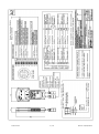
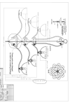
KIT ECO–SONAR ITA L/MIN 200.302.62 ECO - SONAR KIT ENG L/MIN 200.302.63 Lingua Italiana – Unità metriche – l/min English language – Metric units – l/min Versione programma 1.4 Software release 1.4 Questo documento è parte integrante dell’apparecchiatura e deve accompagnarla sempre anche in caso di vendita o cessione. BRAGLIA può apportare revisioni al prodotto e al presente documento senza alcun preavviso This manual is an integral part of the equipment and must accompany it in case of sale or change of ownership. BRAGLIA reserves the right to modify the equipment and this manual at any time and without notice. INSTALLAZIONE, USO E MANUTENZIONE INSTALLATION, USE AND MAINTENANCE SOMMARIO CONTENTS Avvertenze Introduzione Contenuto dell’imballo Specifiche del prodotto Informazioni gestite Installazione Schema di collegamento Pulsantiera Struttura dei menù Programmazione Impiego Menù gestione dati Smaltimento Garanzia 200.1012.2 2 / 16 Warnings Introduction Contents of packaging Product specifications Data managed Installation Wiring diagram Control unit Menu structure Programming Use Data management menu Disposal at the end of service Warranty Rev.03 05/12/2014 AVVERTENZE Tutte le operazioni di installazione devono essere eseguite con la batteria scollegata; L’installazione deve essere eseguita da personale qualificato dotato di attrezzature e strumenti di protezione idonei; Assicurarsi che la batteria sia sempre in buone condizioni e che fornisca la tensione corretta (12Vdc – 13.5Vdc max.); Utilizzare solamente i cavi e gli accessori forniti o con caratteristiche idonee all’uso; Fare attenzione a non rompere, tensionare e strappare i cavi forniti nella confezione. In caso di danni provocati da cablaggi non idonei, si intende risolta ogni forma di garanzia; Evitare di sostare davanti ai sensori attivi; Serrare sempre completamente i connettori completi di guarnizione sulle bobine delle elettrovalvole; Non esporre la pulsantiera ai raggi diretti del sole, alle intemperie e al contatto diretto con i composti chimici; Se necessario, pulire la pulsantiera e gli altri componenti con un panno morbido inumidito utilizzando detergenti neutri; Non aprire mai la pulsantiera. Gli interventi di diagnostica e riparazione possono essere eseguiti solamente da BRAGLIA; Spegnere la pulsantiera ogni volta che non è in funzione per evitare l’esaurimento della batteria ed il surriscaldamento delle bobine delle elettrovalvole. 200.1012.2 WARNINGS The installation works must be done with the battery disconnected; The installation works must be done by qualified technicians with suitable toolings and wearing suitable safety equipment; The battery must be always in good conditions. Check the correct voltage (12 to 13.5Vdc Max.) Use supplied cables and components only or with the same specifications; Do not break or apply tension to cables. The use of unsuitable cables voids warranty; Avoid exposure to activated sensors; Always tighten carefully the supplied connectors and gasket on valve coil; Do not expose the control unit to sun rays, rain and to chemicals direct contact; Always clean the control unit with slightly damp cloth using, if strictly necessary, some neutral soap or similar detergent; Never open the control unit. It has no parts which can be repaired by the users. Return the complete unit to BRAGLIA for diagnostics, repairing or replacing; To avoid battery consumption and solenoid overheating, always switch off the control unit when not in use. 3 / 16 Rev.03 05/12/2014 INTRODUZIONE INTRODUCTION Il Kit Eco – Sonar, installato sull’atomizzatore, controlla automaticamente l’apertura e la chiusura delle sezioni del gruppo di comando elettrico ( non fornito ) composto da valvole della serie M200 / M201 ed è indicato per la gestione dell’irrorazione in piantagioni con massa fogliare discontinua. Rileva la presenza della pianta da trattare mediante l’impiego di una coppia di sensori ad ultrasuoni e controlla la quantità di liquido erogata e residua. The Eco – Sonar kit, fitted to the mist blower, automatically controls the M200/M201 valve assembly (not supplied) operations and sprays to trees only and not to the empty spaces. Consente di ridurre la quantità di principio attivo utilizzato con la conseguente riduzione dei costi e dell’impatto ambientale. The Eco – Sonar detects the trees using two ultrasonic sensors and controls the sprayed and residual tank volume. The Eco – Sonar kit allows chemical use and waste reduction preserving the environments. The valve operation can automatic, manual or semi automatic. La gestione delle valvole può essere impostata in modo automatico, semiautomatico o manuale. CONTENUTO DELL’IMBALLO CONTENTS OF PACKAGING 200.1012.2 200.1317.10 200.1611.6 Manuale Pulsantiera ITA l/min Scatola di derivazione completa per collegamento valvole, sensori e flussometro 2 x 200.1614.1 Sensore 2 x 200.231.10 Protezione sensore 200.231.10 Cavo batteria 12vdc 200.1012.2 200.1012.2 200.1317.11 200.1611.7 Manual Eng l/min control unit Complete wiring box for valves, flow meter and sensor 2 x 200.1614.1 Sensor 2 x 200.231.10 Sensor protection 200.231.10 12Vdc battery cable 4 / 16 Rev.03 05/12/2014 SPECIFICHE DEL PRODOTTO Pulsantiera anti urto a fissaggio magnetico facilmente amovibile. Semplifica le operazioni di verifica nelle fasi di programmazione iniziale / primo impianto. La pulsantiera può essere facilmente rimossa dalla cabina del trattore e riposta con il trainato; Cavi pulsantiera: Alimentazione 12Vdc 1.8m; Connessione scatola derivazione 3.3m; Cavo alimentazione 12Vdc: 2.5m N° 2 Sensori con dadi di fissaggio, connettori a cablare e protezioni sensore. Distanza massima operativa dei sensori: 6m; Scatola di derivazione cablata per collegamento elettrovalvole (4.5m), sensori (6.7m) e flussometro (1.5m). Flussometro non fornito; Presenza tensione di alimentazione; Led di controllo funzionamento sensori e valvole, segnalazione presenza pianta e di allarme per alimentazione, valvole e sensori; Alimentazione 12Vdc – 13.5Vdc max.; Assorbimento max. senza carico: 120mA; Potenza max. ammissibile: 55W a 12vdc; Uscite per N° 2 elettrovalvole da 27W max.; Uscite sensori: N° 2 24Vdc 120mA max.; Ingressi: N°2 ingressi sensori; N°1 ingresso flussometro analogico e digitale; N°1 per rilevatore di sovra pressione N.A. Fusibili: Ø5x20 5 A interno; A lamina automobilistico 7.5 A esterno; Protezione elettronica da corto circuito dei sensori e delle elettrovalvole. PRODUCT DESCRIPTION Shock proof control unit. Magnetic fixing. Easy to remove from tractor cabin. Can be stored on towed sprayer. Easy programming and set up operations; Control unit cables: 12Vdc power supply 4.3m; Cable to wiring box connection 3.3m; Battery connection cable 12Vdc: 2.5m Two ultrasonic sensors with nuts, wiring connector and sensor protection. Max. detected distance: 6m; Wiring box completed with cables for valves (4.5m), sensors (6.7m) and flow meter (1.5m). Flow meter not supplied; Battery power voltage pilot light; LED pilot light for: sensors, valves, tree detection. Alarms for voltage, valves and sensors; Power supply 12Vdc to 13.5Vdc max.; Max. current at no consumption: 120mA; Max. admissible power: 55W at 12Vdc; Outputs for two 27W max. solenoid valves; Sensor outputs: two 24Vdc 120mA max.; Inlets: No. 2 sensors; No. 1 for analogic and digital flow meters; No. 1 for N.A. safety valve; Fuses: Ø5x20 5 A internal; Automotive 7.5 A external; Electronic protection from electric shocks coming from sensors and solenoid valves. INFORMAZIONI GESTITE Prodotto distribuito per ogni albero, numero di piante trattate con conteggio totale, parziale ed azzeramento; Quantità totale e parziale dei litri distribuiti con azzeramento, visualizzazione continua della quantità di litri erogata; Quantità di liquido residuo nel serbatoio; Programma di temporizzazione apertura valvole in decimi di secondo; Possibilità di lavoro in modalità manuale; 5 memorie per la registrazione dei trattamenti effettuati; DATA MANAGED Volume sprayed for each tree, number of sprayed trees with partial and total quantity. Reset function; Total and partial volume sprayed with reset function. Continuous visualization of sprayed flow rate; Tank residue level; Timed valve opening programming (0.1s steps ); Manual mode use; 5 memories to store spraying sessions 200.1012.2 5 / 16 Rev.03 05/12/2014 INSTALLAZIONE Stendere il cavo 200.231.10 e fissare la presa multi polare all’interno della cabina del trattore; Posizionare la pulsantiera 200.1317.10 all’interno della cabina, utilizzando la piastra magnetica, in una posizione confortevole per l’operatore; Stendere i cavi della pulsantiera e collegare la spina alla presa del cavo della batteria; Fissare la scatola di derivazione 200.1611.6 in una posizione facilmente raggiungibile dall’operatore e dal cavo corrispondente della pulsantiera; Collegare il cavo multipolare della pulsantiera alla spina della scatola di derivazione; Installare i sensori 200.1614.1. I sensori devono essere fissati anteriormente all’assieme della ventola in posizione parallela al terreno e perpendicolare rispetto alle piante da trattare; Stendere i cavi solidali con la scatola di derivazione in modo da raggiungere facilmente il gruppo valvole ed i sensori Cablare i connettori dei sensori e delle valvole seguendo lo schema di collegamento allegato; Collegare il flussometro se presente nella configurazione; Collegare i terminali del cavo 200.231.10 alla batteria. 200.1012.2 INSTALLATION Lay the cable 200.231.10 and assemble the socket inside the tractor cabin; Fit the control unit 200.1317.11 inside the tractor cabin using the magnetic plate. Select a comfortable position for the user; Lay the switch box cable and connect the control unit plug to the battery cable socket; Fix the complete wiring box 200.1611.6. The location must be easy accessible to the user and to the connection cable coming from the switch box; Connect the control unit cable plug to the wiring box socket; Assemble the 200.1614.1 sensors. They must be assembled before the blower assembly and positioned parallel to the ground and at 90° to the trees; Lay the cables of the wiring box. These cables must be carefully layered to reach easily both the valve assembly and sensors; Wire the connectors supplied with sensors and valves following the enclosed drawing; Connect the flow meter if supplied; Connect the power supply cable 200.231.10 to the battery. 6 / 16 Rev.03 05/12/2014 200.1012.2 7 / 16 Rev.03 05/12/2014 PULSANTIERA CONTROL UNIT Accensione / On Spegnimento / Off Allarme batteria Battery alarm Allarme valvola Valve alarm Allarme sensore Sensor alarm Accesso menu e selezione Menu access and selection Conferma dati Data confirmation CALCOLATRICE Mostra la quantità di litri spruzzata per pianta CALCULATOR Shows the liquid volume in liters sprayed for each trees. Scorrimento e modifica valori Data reading and data entry Scorrimento e modifica valori Data reading and data entry Modalità automatica Automatic mode Modalità manuale Manual mode Modalità selezionata Selected mode Batteria Battery DISPLAY Litri in cisterna Liters inside tank N° piante trattate Sprayed trees In lavoro sinistra Left side spraying 200.1012.2 Volume irrorato ( l ) – parz./tot. Sprayed volume ( l ) – part./tot. In lavoro destra Right side spraying 8 / 16 Rev.03 05/12/2014 STRUTTURA DEI MENU’ MENU STRUCTURE Premere . Si accede ai menù disponibili per programmare e gestire il funzionamento di ECO – Press to see the available functions for programming and managing the Eco – Sonar. With SONAR. Il pulsante consente di scorrere i menù disponibili in rapida successione. Per ritornare alla button the user can easily slide the available functions. To return to the main display, press visualizzazione iniziale, premere . . LITRI CISTERNA LITERS TANK LITRI PARZIALI PARTIAL LITERS LITRI TOTALI TOTAL LITERS IMPULSI 1 LITRO (per flussometro) PULSE 1 LITER (for flow meter) RITARDO VALVOLA SX 00.0 LEFT VALVE DELAY 00.0 RITARDO VALVOLA DX 00.0 RIGHT VALVE DELAY 00.0 TOTALE PIANTE TOTAL TREES CANCELLARE CONTALITRI PARZIALE CANCEL PARTIAL LITER - COUNTER CANCELLARE PIANTE PARZIALE CANCEL PARTIAL TREES CANCELLARE PIANTE TOTALE CANCEL TOTAL TREES VERSIONE (Release software) VERSION (Software release) IMPOSTAZIONI DI FABBRICA FACTORY SETTINGS PROGRAMMAZIONE PROGRAMMING Prima di utilizzare Eco - Sonar si devono introdurre i parametri di base per consentire il corretto funzionamento del flussometro (se installato) e del tempo di ritardo delle elettrovalvole dopo il rilevamento della pianta da parte del sensore. Before using the Eco – Sonar, the user must enter the data to manage the flow meter (if fitted) and the valve operation delay after the tree detection from sensor. Questi parametri devono essere impostati una sola volta. Dovranno essere modificati nel caso sia necessario utilizzare una diversa quantità di liquido in cisterna e in coltivazioni con una diversa distribuzione delle piante. These data must be entered one time only. These data must be modified when changing the total volume of liquid inside the tank or when the trees density is quite different. In case of system errors, the warning LED lights on the switch box will display the error occured. In caso di errore in una qualsiasi parte del sistema, il pannello di controllo indica la causa mediante l’accensione dei LED di allarme corrispondenti. 200.1012.2 9 / 16 Rev.03 05/12/2014 1) LITRI CISTERNA 1) LITERS TANK Premere Press Premere ; Sul display appare “LITRI CISTERNA 00000”; Press ; The display will show “LITERS TANK 00000”; Premere due volte Press two times Le migliaia (00000) lampeggiano. Premendo The second digit (00000) will flash. Pressing e ; ; si modifica il valore numerico; Premere ; Le centinaia (00000) lampeggiano. Premendo e si modifica il valore numerico; Impiegando la stessa modalità impostare , se necessario, il valore per le decine e le unità; Con cisterna. si conferma il valore di litri in E’ possibile entrare nel menù seguente solo se il litri cisterna sono confermati (nessun valore deve lampeggiare). Premere premere ; ; and the numeric value will change; Press ; The third digit (00000) will flash. Pressing the numeric value will change; Using the same process we will enter the other digits; Pressing and the data will be stored. It will be possible to enter the next menu only if the liter tank data is stored (no digit flashing). Press to return to the main menu or press for the next menu. per ritornare al menù iniziale oppure per passare ai menù successivi. 2) IMPULSI 1 LITRO Questo è un dato impostato dal fornitore del flussometro*. Se impostato, ad esempio, su 617 indica che 617 impulsi del sensore del flussometro* equivalgono a un litro di fluido erogato. 2) PULSE 1 LITRE This value is preset by the flow meter* manufacturer. If set for example to 617, it means that 617 pulses from flow meter* sensor is equal to 1 liter of liquid flowing trought the flow meter body. *IMPORTANTE: il flussometro non è compreso e deve essere acquistato a parte. La sua assenza non pregiudica il funzionamento del sistema ma in questo modo non è possibile misurare la quantità di liquido erogata e pertanto limita le funzionalità del prodotto. IMPORTANT: the flow meter is not included and must be purchased aside. The Eco – Sonar will work also without a flow meter but not knowing the volume sprayed will limit the information supplied from this system. Per inserire o modificare questo dato: To enter this data: Premere ; Sul display si visualizza il valore “LITRI CISTERNA” precedentemente impostato; Press ; The display will show the “LITERS TANK” value previously entered; Premere tre volte per visualizzare il menù “ IMPULSI / LITRO 0000“; Press three times LITRE 0000” menu; 200.1012.2 10 / 16 to show the “PULSE 1 Rev.03 05/12/2014 Premere due volte . Le centinaia (0000) lampeggiano. Premendo il valore numerico; Premere e si modifica ; will flash. Pressing value will change; . The second digit (0000) and the numeric Press Le decine (0000) lampeggiano. Premendo The third digit (0000) will flash. Pressing e si modifica il valore numerico; Impiegando la stessa modalità, impostare il valore per le unità; the numeric value will change; Using the same process we will enter the other digits; Pressing Premendo impostato. premere si conferma il valore Press ; and the data will be stored. to return to the main menu or press for the next menu. per ritornare al menù iniziale oppure per passare ai menù successivi. 3) RITARDO VALVOLE SINISTRA E DESTRA Questo valore deve essere inserito dall’utente in funzione della velocità del trattore e della distanza tra i sensori e le elettrovalvole. Quando i sensori non intercettano più la pianta da irrorare emettono un segnale che chiude l’elettrovalvola compromettendo l’irrorazione completa della pianta stessa. Il valore del ritardo delle elettrovalvole è misurato in secondi. Quando il sensore non intercetta più la pianta la chiusura dell’elettrovalvola è ritardata del tempo pre impostato in modo che la pianta sia irrorata completamente. Per inserire o modificare questo dato: Premere Premere quattro volte per visualizzare il “ RITARDO VALVOLA SX 00.0”; ; Premere tre volte Premere Premere per VALVOLA DX 00.0”. 3) LEFT AND RIGHT VALVE DELAY This value must be entered by the user and must be based on the tractor speed and the distance from sensor and the valve unit. When the sensor stops detecting the tree, it send a signal that immediately close the valve compromising the complete spray coverage of the tree. The delay of valves is measured in seconds. When the sensor stops detecting the tree, the valve shut off is delayed of this pre set value so that the complete tree is sprayed. To enter this value: Press Press four times DELAY 00.0”; to show “LEFT VALVE Press three times to select the third digit per evidenziare il numero dopo il punto (00.0). Premendo modifica il valore numerico; Press two times Premere e a “ RITARDO Ripetere i passi precedenti e premere (00.0). Pressing value will change; and the numeric si ; accedere ; Press ; Press to show “RIGHT VALVE DELAY 00.0”; Repeat the same step as before and then press to return to the main menu or press for the next menu. per tornare al menù iniziale oppure premere per passare ai menù successivi. 200.1012.2 11 / 16 Rev.03 05/12/2014 IMPIEGO USE Il display di controllo mostra in alto la quantità di litri introdotta in cisterna, il contatore parziale di piante trattate e la quantità di liquido che si sta irrorando. The upper section of the main control display shows the litres introduced into the tank, the partial counter of trees and the quantity of liquid being sprayed. Nella parte bassa del display si controlla la modalità di lavoro dei sensori e delle valvole delle due raggiere destra e sinistra. In the lower section the user will control the operating mode for both sensors and valves of the right and left booms. Questo diagramma mostra la modalità di lavoro selezionata. I LED indicano quali componenti del sistema sono in lavoro. The diagram shows the selected operating mode. The LED show which component is working. La modalità di lavoro può essere automatica, manuale o semi automatica. 1) MODALITA’ AUTOMATICA Attendere la visualizzazione di ‘MODALITA’ DESTRA E SINISTRA’ nella parte inferiore del display. Eco - Sonar è dotato di due sensori (uno per lato) per rilevare la presenza delle piante da irrorare. In seguito all’inserimento dei dati di programmazione richiesti, con questa modalità si gestisce, senza l’intervento dell’operatore, l’apertura e la chiusura delle elettrovalvole utilizzando i segnali provenienti dai sensori. Contemporaneamente si tiene sotto controllo la quantità di liquido erogata. I tre pulsanti consentono di gestire in modo automatico le singole sezioni destra e sinistra oppure entrambe le sezioni (pulsante centrale). Le sezioni attive in modalità automatica sono evidenziate sul display con la lettera A. 200.1012.2 The operating mode can be automatic, manual or semi automatic. 1) AUTOMATIC MODE Wait until the display shows ‘FUNCTION MODE RIGHT AND LEFT’ on the bottom part of the screen. The Eco – Sonar is supplied with two sensors (one for each side) to detect trees to be sprayed. After the programming step required, with this operating mode the system will manage the valve operation using only the inputs coming from the sensors and will keep under control the sprayed volume. The three buttons controls the right, left and right + left (central button) boom sections. The spraying sections activated in automatic mode are displayed with the letter A on the main screen. 12 / 16 Rev.03 05/12/2014 2) MODALITA’ MANUALE 2) MANUAL MODE Nella modalità manuale i sensori non sono attivi. L’apertura e la chiusura delle elettrovalvole è demandata all’operatore. I tre pulsanti consentono di gestire manualmente le singole sezioni di destra e sinistra oppure entrambe le sezioni (pulsante centrale). In the manual mode the sensors are not working. The equipment only sprays when the selected boom section button is pressed by the user. The central button operates both valves. Le sezioni attive in modalità manuale evidenziate sul display con la lettera M. The spraying sections activated in manual mode are displayed with the letter M on the main screen. sono 3) MODALITA’ SEMI AUTOMATICA Se le condizioni della coltivazione lo richiedono, è possibile utilizzare ECO- SONAR in modalità mista automatico + manuale. Per esempio è possibile gestire la modalità automatica sul lato destro e quella manuale sul lato sinistro. 3) SEMI AUTOMATIC MODE The Eco – Sonar can be used in this mode to operate, for example, one side in automatica mode and the other one in manual mode. MENU’ GESTIONE DATI DATA MANAGEMENT MENU 1) LITRI PARZIALI E TOTALI Questo menù serve per visualizzare la quantità di liquido parziale e totale irrorata. La quantità parziale può essere azzerata mentre la quantità totale no. 1) PARTIAL AND TOTAL LITRES This menu will show the partial and total volume of liquid sprayed. The partial quantity can be set to zero but not the total quantity. Premere Press Premere . Si visualizzerà il valore numerico dei litri parziali; Press . The display will show the value of the partial volume of liquid sprayed; Premere Press ; per ritornare al menù iniziale oppure premere per visualizzazione dei litri totali; Premere passare per ritornare al menù iniziale. 2) TOTALE PIANTE Questo menù serve per visualizzare il numero totale di piante trattate. In lavoro il display visualizza il numero delle piante parziale trattate in una sessione. 200.1012.2 press sprayed; alla Press ; to return to the main menu or to display the total volume of liquid to return to the main menu; 2) TOTAL TREES This menu will show the total quantity of trees sprayed. During the spraying session the display will show the partial number of trees sprayed. 13 / 16 Rev.03 05/12/2014 Premere ; Press ; Premendo sei volte si visualizzerà il valore numerico delle piante totali trattate 0000000; Pressing six times the display will show the total number of trees sprayed 0000000; Premere Press per ritornare al menù iniziale. NOTA IMPORTANTE: il contatore delle piante contabilizza un solo lato della pianta (quella sottoposta all’irrorazione) per ogni rilevazione del sensore. to return to the main menu. IMPORTANT NOTICE: the trees counter will detect, for each sensor detection, only one side of the tree sprayed. 3) CANCELLARE LITRI PARZIALI 3) CANCEL PARTIAL LITER – COUNTER Premere ; Premendo sette volte si visualizzerà “CANCELLARE CONTALITRI PARZIALE”; Premere. . Apparirà “CANCELLATO”; Premere per tornare al menù iniziale. Press ; Pressing seven times the display will show “CANCEL PARTIAL LITER – COUNTER”; Press . “CANCELLED”; Press The display will show to return to the main menu. 4) CANCELLARE PIANTE PARZIALE 4) CANCEL PARTIAL TREES Premere Press Premendo otto volte si “CANCELLARE PIANTE PARZIALE”; Pressing eight times the display will show “CANCEL PARTIAL TREES”; Premere. Apparirà “CANCELLATO”; Press . “CANCELLED”; Premere per tornare al menù iniziale. Press ; visualizzerà ; The display will show to return to the main menu. 5) CANCELLARE PIANTE TOTALE 5) CANCEL TOTAL TREES Premere Press Premendo nove volte si “CANCELLARE PIANTE TOTALE”; Pressing nine times the display will show “CANCEL TOTAL TREES”; Premere. Apparirà “CANCELLATO”; Press . “CANCELLED”; Premere per tornare al menù iniziale. Press 200.1012.2 ; visualizzerà 14 / 16 ; The display will show to return to the main menu. Rev.03 05/12/2014 NOTA Può accadere che il contatore delle piante trattate sia in disaccordo con il numero di piante che l’utilizzatore ha rilevato manualmente, fornendo un valore superiore. Questo può accadere in quanto il sensore rileva tutto quello che incontra, sia esso una pietra, un arbusto o una persona. NOTE Some times there will be some discrepancy between the number of trees detected and those manually checked by the end user. This can occur because the sensor will detect everything within their range (bushes, rocks and humans also). Inoltre se la massa fogliare è continua tra i due tronchi di una stessa pianta, il sensore rileva un solo segnale. Se invece lo spazio libero nella vegetazione è compreso tra 60 e 90 centimetri il sensore rileva due segnali continuando l’erogazione grazie alla programmazione del ritardo dell’elettrovalvola eseguita precedentemente. Furthermore, if the leaf mass is without interruption between two trunks of the same tree, the sensors will detect only one tree. If there is a 60 to 90cm free space between the leaf mass of these two trunks, the sensor will detect two trees owing to the valve delay programming. SMALTIMENTO Questo prodotto non può essere smaltito come rifiuto domestico. E’ necessario smaltirlo secondo lo schema di raccolta degli apparecchi elettrici ed elettronici. Per ulteriori informazioni sullo smaltimento di questo apparecchio, contattare l’ Ente della propria città o il servizio di smaltimento rifiuti. Il recupero dei materiali aiuterà a preservare le risorse naturali. DISPOSAL AT THE END OF SERVICE This product can not be disposed as household waste. It must be disposed by handling it over to the applicable take-back scheme for the recycling of electrical and electronic equipment. For more information concerning the recycling of this product, please contact your waste disposal service. The recycling of materials will help to preserve the environment. GARANZIA I nostri prodotti sono controllati secondo campionamento statistico contro ogni difetto di produzione. La garanzia ha durata di 12 mesi dalla data di consegna con sostituzione o riparazione gratuita dei prodotti che presentino eventuali difetti di fabbricazione. Ci riserviamo la facoltà di ispezionare il prodotto, la sua installazione e di verificarne le modalità di impiego. I prodotti eventualmente difettosi devono essere ritornati franco di porto. Se i prodotti saranno ritenuti coperti da garanzia, le spese di riparazione e sostituzione saranno a nostro carico. Non verranno riconosciute spese accessorie e qualsiasi altra richiesta di danni o indennizzi. WARRANTY Our products are inspected by MIL STD sampling against any manufacturing defects. The warranty is valid for 12 months from the date of delivery with replacement or repair free of charge of products having proven manufacturing faults. We reserve the right to inspect the returned products, to verify the installation and use. The faulty products must be returned to us freight prepaid while all repair and replacement charges will be at our expenses. We will not refund any further expenses nor will accept any damage claims. 200.1012.2 15 / 16 Rev.03 05/12/2014 Via Martin Lutero, 4 – I 42029 Masone – Reggio Emilia – ITALY – UE Tel. 0522 340648 – Export ++39 0522 340648 Fax Italia 0522 345025 – Fax Export ++39 0522 340897 Internet : http://www.braglia.it – Email : [email protected] CF e P.IVA 00443530357 200.1012.2 16 / 16 Rev.03 05/12/2014