1
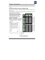
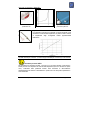
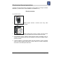
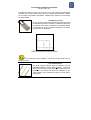
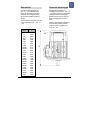
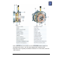
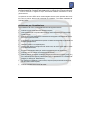
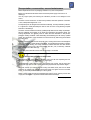
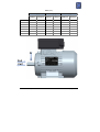
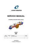
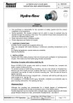
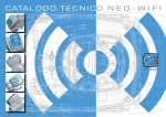
MONO MOTORI ELETTRICI MONOFASE SINGLE PHASE MOTORS DELPHI MOTORI ELETTRICI TRIFASE THREE PHASE MOTORS motive power transmission Technical Manual delphi series universal motors rev.12 page 1 of 72 indice Titolo Caratteristiche tecniche Protezioni elettriche e termiche Collegamento elettrico Schemi di collegamento Messa in servizio Condizioni di funzionamento Tettuccio parapioggia Motori autofrenanti serie Delphi AT.. Motori servoventilati - serie SV Encoder Trasporto, conservazione, uso e manutenzione Lubrificazione cuscinetti Lista ricambi Marcatura CE Dichiarazione di conformità index title Technical characteristics Electrical and thermal protections Electrical connection Wiring diagrams Start Working conditions Rain shield Brake motors AT.. series Assisted power cooling – SV series Encoder Transportation, conservation, use and maintenance Bearings Lubrication Spare parts list CE marking Conformity Declaration Technical Manual delphi series motors rev.12 page 2 of 72 Caratteristiche tecniche I motori Motive DELPHI (trifase) e MONO (monofase) sono realizzati secondo le norme internazionali di unificazione ed adatti ad un uso universale; ogni dimensione, per tutte le forme costruttive, è stata dedotta facendo riferimento alle tabelle relative alla norma IEC 72-1; Le forme costruttive realizzate, secondo IEC 34-7, sono B3, B5, B14, B3/B5, B3/B14, B14B I motori asincroni trifase Motive sono di tipo chiuso, con ventilazione esterna. La carcassa, fino al tipo 132 incluso, è ottenuta da pressofusione di lega d’alluminio, dal 160 in poi da fusioni in ghisa. Hz 50 56-132 Tutti i motori trifase sono multitensione, e multifrequenza 50/60Hz secondo i valori esposti a destra classe di isolamento F, servizio continuo S1*, protezione IP55. Il rendimento è classificato in targa IE2/IE3 come da norma IE 60034-30 size Tutti i dati di caratterizzazione dei motori, quali prestazioni e dimensioni sono dettagliatamente illustrati nel catalogo e nel sito www.motive.it. Volts 60 *S1 - Servizio continuo: funzionamento a carico costante. 230 220 240 260 220 265 280 400 380 415 440 380 460 480 (Pn=100%) (Pn=100%) (Pn=100%) (Pn=110%) (Pn=100%) (Pn=115%) (Pn=120%) 400 380 415 440 380 460 480 690 660 720 760 660 795 830 (Pn=100%) (Pn=100%) (Pn=100%) (Pn=110%) (Pn=100%) (Pn=115%) (Pn=120%) N a 132-400 50 b Tmax c d 60 a= carico b= perdite elettriche c= temperature d= tempo N= tempo funzionamento a carico costante Tmax= temperatura massima raggiunta Technical Manual delphi series motors rev.12 page 3 of 72 Technical characteristics Motive motors are built according to international standard regulations for universal use; each size throughout the construction forms is calculated with reference to the tables of standard IEC 72-1; The shapes built per IEC 34-7, are B3, B5, B14, B3/B5, B3/B14, B14B Motive asynchronous three-phase are closed and externally ventilated. The frame, up to 132 included, is made in die casting aluminium alloy, from 160the frame is made in cast iron All technical details, as performance data and dimensions, are thoroughly described in the product catalogue and in www.motive.it F Class insulation, Continuous duty service S1*, IP55 protection Efficiency is classified on the plate IE2/IE3 according to the norm IE 60034-30 *S1 - Continuous duty service: operating at constant load size Volts Hz 50 56-132 All three-phase motors are multiple voltage, and multiple frequency 50/60Hz, according to the data on the right 60 N 230 220 240 260 220 265 280 400 380 415 440 380 460 480 (Pn=100%) (Pn=100%) (Pn=100%) (Pn=110%) (Pn=100%) (Pn=115%) (Pn=120%) 400 380 415 440 380 460 480 690 660 720 760 660 795 830 (Pn=100%) (Pn=100%) (Pn=100%) (Pn=110%) (Pn=100%) (Pn=115%) (Pn=120%) a b Tmax c d Technical Manual delphi series motors rev.12 132-400 50 60 a= load b= electric losses c= temperature d= time N= steady load operating time Tmax= max temperature achieved page 4 of 72 Protezioni elettriche e termiche le protezioni devono essere scelte in base alle specifiche condizioni di esercizio secondo le norme EN 60204-1 (per motori destinati ad essere installati in atmosfere esplosive, vedi EN60079-14 ed EN61241-14). Protezioni esterne Si possono avere: 1. protezioni contro i sovraccarichi; questa protezione si può ottenere tramite relè termico, che comanda un interruttore di potenza automatico sezionatore 2. protezione contro le sovracorrenti, tramite relè magnetico che controlla un interruttore automatico di potenza sezionatore , o con fusibili; questi devono essere tarati sulla corrente a rotore bloccato del motore. protezione contro la sovravelocità, ad esempio nel caso in cui il carico meccanico possa trascinare il motore e questa possa diventare una condizione di pericolo. protezione, se particolari condizioni di funzionamento in sincronia con altre macchine o parti di macchine lo richiedono, contro l’interruzione della tensione di alimentazione o la riduzione della stessa tramite relè di minima tensione che controlla un interruttore automatico di potenza sezionatore 3. 4. Technical Manual delphi series motors rev.12 page 5 of 72 Protezioni termiche interne: (secondo CEI 2-3 / IEC 34-1) Le protezioni elettriche presenti sulla linea di alimentazione del motore possono essere insufficienti ad assicurare la protezione dai sovraccarichi. Infatti, se peggiorano le condizioni di ventilazione, il motore si surriscalda ma le condizioni elettriche non si modificano e ciò inibisce le protezioni sulla linea. Si ovvia a questo inconveniente installando intimamente protezioni sugli avvolgimenti: dispositivo bimetallico PTO è un dispositivo elettromeccanico che, normalmente chiuso, una volta raggiunta la temperatura di scatto si apre elettricamente; si ripristina automaticamente quando la temperatura scende sotto il limite di scatto. Tr= opening temperature (il motore si ferma) Ti= re-closing temperature (il motore torna a funzionare) il dispositivo PTO non è ammesso per motori “Delphi Ex - II 3G Ex nA” ed altri motori ATEX per Gas dispositivo termistore PTC questo dispositivo varia la sua resistenza in modo repentino e positivo una volta raggiunta la temperatura di intervento. I motori “Delphi Ex - II 3G Ex nA” e comunque tutti i motori dal tipo 160 al tipo 355L sono equipaggiati di serie con 3 termistori PTC immersi nell’avvolgimento, con temperatura di intervento di 120-130°C nei motori in classe F (standard) (o 150-160°C nei motori in classe H, Technical Manual delphi series motors rev.12 page 6 of 72 comunque non ammessi in “Delphi-Ex”). grandezza 160-400 posizione PTC Ti= temperatura di intervento pressacavo per PTC dispositivo PT100 è un dispositivo che varia con continuità, e in modo crescente, la sua resistenza in funzione della temperatura. Si presta al rilievo continuo di temperatura degli avvolgimenti tramite apparecchiature elettroniche. Nel rispetto della norma IEC34-1 tutti i motori possono sopportare sovraccarichi di 1,5 volte la corrente nominale per 2 minuti e 1,6 volte la coppia nominale per 15 secondi (V e Hz nominali) Avvertenza per motori ATEX: Se alimentati da un dispositivo inverter, o nel caso in cui non siano ventilati, i motori devono essere provvisti di un dispositivo di controllo della temperature (PTO non ammessi in questo caso). L’intervento della protezione termica deve assicurare la disconnessione dell’alimentazione del motore. L’alimentazione in questo caso non deve potersi ripristinare in modo automatico. Technical Manual delphi series motors rev.12 page 7 of 72 Electrical and thermal protections protections must be chosen based on the specific running conditions, according to standards EN 60204-1 (for ATEX motors, see also EN60079-14 and EN61241-14). External protections It is possible to have: 1. Protection against overloads. A thermal cut-out relay, which automatically controls a knife switch. 2. Protection against peak currents by magnetic relay that controls an automatic knife switch, or by fuses; these must be set to the locked rotor current. 3. if the application requires, protection against excessive speed of the electric motor, for example if the mechanical load may drive the electric motor itself and thereby create a hazardous situation. 4. If special conditions or synchronised operation with other machines or parts of machines require it, protection against power failures or dips by means of a minimum voltage relay that controls an automatic power knife switch. Technical Manual delphi series motors rev.12 page 8 of 72 Inner thermal overload cut-out switches (per CEI 2-3/IEC 34-1) The electrical protections on the motor power line may not be sufficient to protect against overloads. If the cooling conditions worsen, the motor overheats but the electrical conditions do not change, which inhibits line protections. Installing built-in protections on the windings solves this problem: bimetallic device “PTO” this is a normally-closed electromechanical device that opens when the threshold temperature is reached; it automatically resets when the temperature falls below the threshold level. Bimetallic devices are available with various intervention temperatures and without automatic reset, per EN 60204-1. Tr= Opening temperature (motor stops) Ti= Re-closing temperature (motor works again) PTO is not allowed in motors “Delphi Ex - II 3G Ex nA” and other ATEX motors for Gas environments PTC thermistor device this device promptly, positively adjusts its resistance once the threshold temperature is reached. Motors “Delphi Ex - II 3G Ex nA” and all motors from type 160 to type 355L are equipped with 3 PTC thermistors in the winding, with temperature intervention of 120130°C in Class F motors (standard) (150-160°C in H Class motors, not Delphi Ex) Technical Manual delphi series motors rev.12 page 9 of 72 PTC position Ti= activating temperature Size 160-400 PTC cable gland PT100 device this is a device that continuously, increasingly adjusts its resistance according to the temperature. It is useful for constant measuring of the winding temperatures using electronic In compliance with IEC34-1, all motors can be exposed to overload conditions of 1,5 times the rated current for 2 min and 1,6 times the rated torque for 15 sec (at rated V and Hz) According to IEC34-1 norm, all motors withstand a temporary overload of 1.5 times the rated current for 2 minutes, and 1.6 times the rated torque for 15 seconds (at rated V and Hz) Warning for atex motors: When connected to inverter, or in case that the motor is not ventilated, motors must be provided of a temperature control by means of sensors (PTO not allowed in this case). The thermal protection intervention must assure the power supply disconnection. He motor power supply system must then not be able return connected automatically. Technical Manual delphi series motors rev.12 page 10 of 72 collegamento elettrico electrical connection Le operazioni di collegamento alla rete elettrica The operations for the connection to the electric (valide anche per circuiti ausiliari) devono essere network (valid for auxiliary circuits, too) must be effettuate in ottemperanza alle seguenti prescrizioni: performed in compliance with the following qualunque operazione sull’impianto deve essere indications: il motore deve essere disattivato ed isolato; ̀ any operation on the plant must be run by trained personnel; assicurarsi che non sia possibile un riavvio accidentale; ̀ the motor must be disabled and isolated; make sure that a casual start can not occur; accertarsi dell’assenza di tensione; ̀ make sure that there is no voltage; dove la rete non sopporta la corrente d’inserimento diretto, il motore può essere avviato mediante un commutatore stellatriangolo. Ciò può avvenire soltanto nei motori il cui collegamento degli avvolgimenti per la tensione nominale è triangolo. ̀ If the network does not sustain the direct input voltage, the motor can be started by means of a star/delta commutator, which is possible only in motors where the connection of the winding for rated voltage is delta. effettuata da personale addestrato; ̀ l’allacciamento deve essere effettuato in modo tale da garantire un collegamento elettrico duraturo e sicuro; assicurare il corretto dimensionamento dei cavi di alimentazione ̀ assicurarsi che nella scatola collegamenti non siano presenti nè corpi estranei, né sporcizia o umidità. Chiudere i pressacavi non utilizzati e serrare bene il coperchio della scatola coprimorsettiera per prevenire la penetrazione di polvere ed acqua; ̀ nel caso di motori dotati di freno (serie AT..), verificare il corretto funzionamento del freno prima della messa in servizio; ̀ il cambio del senso di rotazione si può ottenere intercambiando le due fasi. Technical Manual delphi series motors rev.12 the electric connection must be made in order be long-lasting and safe; assure correct dimensioning of power supply cables make sure that in the box for the connection there is neither foreign bodies, nor dirty/humid parts. Close the unused cable glands and tight terminal box lid in order to prevent the entrance of dust and water; when testing without output components secure the keyway; in motors with brake (AT.. series), please verify the brake switching before the starting process; you can change to counter-rotation an be obtained by interchanging the two phases. page 11 of 72 Schemi di collegamento (DELPHI 3PH) Motore tipo 56 63-100 112 132 pressacavo diam cavi mm M16 3-7 M20 10-14 M25 9-16 M32 13-20 160-180 200-225 250-355 400 2xM40 2xM50 2xM63 3xM63 20-26 25-31 29-35 29-35 Il collegamento dei cavi d'alimentazione alla morsettiera deve essere eseguito capocorda su capocorda Coppia di serraggio (N.m) sui dadi delle morsettiere: M4 M5 M6 M8 M10 M12 M16 steel 2 3,2 5 10 20 35 65 brass 1 2 3 6 12 20 50 Nm Technical Manual delphi series motors rev.12 page 12 of 72 Gli avvolgimenti dei motori trifase serie Delphi possono essere collegati a stella o a triangolo. U1 U1 V1 W1 W1 V1 Collegamento a stella Il collegamento a stella si ottiene collegando insieme i terminali W2, U2, V2 e alimentando i terminali U1, V1, W1. Collegamento a triangolo Il collegamento a triangolo si ottiene collegando la fine di una fase all’inizio della fase successiva. Per gli schemi di collegamento dei motori autofrenanti, vedi il capitol “serie Delphi AT...”. Technical Manual delphi series motors rev.12 page 13 of 72 Wiring Diagrams (DELPHI 3PH) Motor type 56 63-100 112 132 Cable gland Cables diam mm M16 3-7 M20 10-14 M25 9-16 M32 13-20 160-180 200-225 250-355 400 2xM40 2xM50 2xM63 3xM63 20-26 25-31 29-35 29-35 Correct and wrong connection of the power cables terminal lugs to the terminal block: Torque (Nm) on the terminal block nuts M4 M5 M6 M8 M10 M12 M16 steel 2 3,2 5 10 20 35 65 brass 1 2 3 6 12 20 50 Nm Technical Manual delphi series motors rev.12 page 14 of 72 Delphi series three phase motors can be connected “Star” or “Delta” . U1 U1 V1 W1 W1 V1 Star connection Star connection is obtained by connecting together the terminals W2, U2, V2 and supplying the terminals U1, V1, W1. Delta connection Delta connection is obtained by connecting the end of a phase with the beginning of the following one. series” chapter For brake motors wiring diagrams, see “AT.. Delphi Technical Manual delphi series motors rev.12 page 15 of 72 Double polarity motor, single winding (Dahlander) Motore doppia polarità singolo avvolgimento (Dahlander) High-speed connection Low-speed connection Connessione alta velocità Connessione basa velocità W2 V2 W1 W1 U2 V1 U1 V1 U1 To use the 2 speeds, you must adopt a 6+1 wires cable and connect an external switch Per sfruttare entrambe le velocità, adottare un cavo a 6+1 fili e collegare un commutatore esterno Technical Manual delphi series motors rev.12 page 16 of 72 Double polarity motor, with double winding High-speed connection Connessione alta velocità Motore doppia polarità a doppio avvolgimento Low-speed connection Connessione bassa velocità U2 V2 W2 W1 V1 U1 To use the 2 speeds, you must adopt a 6+1 wires cable and connect an external switch Per sfruttare entrambe le velocità, adottare un cavo a 6+1 fili e collegare un commutatore esterno Technical Manual delphi series motors rev.12 page 17 of 72 Single phase motors MONO Technical Manual delphi series motors rev.12 Motori monofase MONO page 18 of 72 NEO-WiFi Technical Manual delphi series motors rev.12 (motor 230VΔ/400VY) page 19 of 72 NEO-WiFi Technical Manual delphi series motors rev.12 (motor 400VΔ/690VY) page 20 of 72 Messa in servizio Start Prima dell’avviamento del motore effettuare un controllo generale, assicurandosi di aver rispettato tutte le procedure di installazione. In particolar modo verificare: ̀ Before starting make an overall check of the motor to make sure that all the indications about installation have been applied. In particular che la tensione di alimentazione del motore corrisponda a quella prevista in targa; ̀ make sure that the voltage of the motor is equivalent to the one expected (see motor plate) and controllare il raccordo della piastrina di collegamento, serrare tutti i suoi dadi e fissare il coperchio della morsettiera avendo cura di non danneggiare la guarnizione; ̀ check the union of the connecting link, close all its dies and secure the cover of the terminal board without damaging the gasket; verificare la libera rotazione dell’albero manualmente; ̀ check if there is voltage in all the phases and controllare se tutte le fasi hanno tensione e, possibilmente, misurare che il loro valore sia conforme al valore nominale di targa. Technical Manual delphi series motors rev.12 verify the free rotation of the motor shaft manually; eventually measure their value to check their conformity to the plate values. page 21 of 72 Condizioni di funzionamento Umidità: L’equipaggiamento elettrico deve essere in grado di funzionare con un’umidità relativa compresa tra il 30 ed il 95% (senza condensazione). Effetti dannosi di condensazioni occasionali devono essere evitati mediante un progetto adeguato dell’equipaggiamento oppure, se necessario, mediante misure aggiuntive (per es. scaldiglie incorporate per il riscaldamento, fori di drenaggio). Gli avvolgimenti sono impregnati a vuoto (vacuum) – procedimento VPI – senza evaporazione, e adatti perciò a climi tropicali Altitudine e temperatura: le potenze indicate si intendono per motori la cui utilizzazione normale di funzionamento è prevista ad una altezza inferiore a 1000m sul livello del mare ed una temperatura ambiente compresa tra i -15° e +40°C per motori di potenza nominale uguale o superiore a 0,6kW (IEC 34-1): per condizioni di esercizio diverse da quelle specificate (altitudine e/o temperatura superiori) la potenza diminuisce del 10% per ogni 10° di sovratemperatura, e dell’8% per ogni 1000 metri di altitudine in più. Non è consentito usare motori idonei all’utilizzo in atmosfere esplosive in ambienti con temperature fuori dal range -20°C +40°C. Non è necessario ridurre la potenza nominale nel caso in cui ad una altitudine superiore ai 1000 m e inferiore ai 2000 m corrisponda una temperatura ambiente massima di 30°C o 19°C massimi per un funzionamento ad altitudini tra i 2000 m ed i 3000 m. Tensione - Frequenza: E’ ammessa al massimo una variazione della tensione del +-10% del valore nominale. In questo intervallo i ns motori forniscono la potenza nominale. Nel funzionamento continuo, ai limiti di tensione sovraindicati, si può avere una fluttuazione della temperatura di riscaldamento fino a +/- 20°C max. Isolamento: l’avvolgimento dello statore è eseguito con filo di rame ed isolamento di cava in classe F, che garantisce una elevata protezione alle sollecitazioni elettriche e meccaniche. Le temperature massime limite (Tmax) delle classi di isolamento definite dalle norme EN 60034-1 sono Classe T (°C) Tmax (°C) A 60+5° 105 E 75+5° 120 B 80+5° 130 F 105+5° 155 H 125 180 Technical Manual delphi series motors rev.12 I motori Motive, al fine di garantire un servizio continuo S1, sono costruiti in modo tale da avere un livello di riscaldamento classe B o inferiore, quindi ampiamente sotto il loro limite di protezione della classe F. page 22 of 72 Working conditions Humidity: The electrical equipment must be able to work with a relative humidity between 30 and 95% (without condensation). Damaging effects of occasional condensation must be avoided by adequate equipment design or, if necessary, by additional measures (for example, built-in heating device, drainage holes). The winding are vacuum pressure impregnated (VPI process, evaporation free, medium category), and are therefore suitable for tropical climates Altitude and temperature: the powers indicated are intended for regular use at altitudes below 1000 mt above sea level and a temperature between +5°C and +40°C for motors having a rated power below 0.6 kW, or between -15°C and 40°C for motors having a rated power equal to or greater than 0.6 kW (IEC 34-1): For higher altitude and/or temperature the power decreases of 10% each 10°C of higher temperature, and of 8% for each 1000 mt of higher altitude. It is not allowed to use motors designed for explosive atmospheres in environment temperatures out of -20°C and +40°C range. Voltage - Frequency: The maximum variation of the supply voltage is +-10%. Within this tolerance Motive motors supply the rated power. Within such range, the temperature rise of the motor can fluctuate up to +/-20°C Insulation: the stator winding is made of resin coated copper wire and insulation materials in F class, that provide high protection against electrical and mechanical stresses. The max temperatures (Tmax) for insulation classes defined by EN 60034-1 standard are Class T (°C) Tmax (°C) A 60+5° 105 E 75+5° 120 B 80+5° 130 F 105+5° 155 H 125 180 The temperature rise of the Delphi series is class B or lower, much under the limits of F class motors, thus permitting a longer motor life Technical Manual delphi series motors rev.12 page 23 of 72 Rain shield Tettuccio parapioggia For outdoor applications with V5 – V18 – V1 – V15 installation(shaft down), we recommend to mount a rain shield. This configuration may also be used in textiles processing industry. Per applicazioni all’aperto con montaggio in posizione V5 – V18 – V1 – V15 (albero in basso) è consigliabile montare un tettuccio parapioggia. Questa esecuzione si può utilizzare anche in ambienti per lavorazioni tessili The rain shield is compulsory in ATEX motors with mounting V5 – V18 – V1 – V15 Tipo L 63 71 80 90S 90L 100 112 132S 132M 160M 160L 180M 180L 200L 225S 225M 250M 280S 280M 315S 315M 315L 355M 355L 215 323 369 403 428 469 453 573 613 770 825 915 955 1025 1155 1160 1220 1265 1315 1540 1570 1680 1840 1870 Technical Manual delphi series motors rev.12 Il tettuccio para-pioggia è obbligatorio nei motori atex, quando gli stessi vengono montati in posizione V5 – V18 – V1 – V15 L page 24 of 72 Serie Delphi AT.. AT.. Delphi series I motori autofrenanti serie Delphi ATDC, AT24, ATTDe ATTD24 prevedono l’impiego di freni a pressione di molle alimentati in corrente continua, calettati saldamente su uno scudo in ghisa nella parte posteriore del motore. AT24 e ATTD24 sono dotati di freni a 24V per poter essere alimentati direttamente dalle separate uscite24V di cui la maggior parte degli inverter sono dotati. Si possono effettuare due tipi diversi di regolazione per i motori ATDC e AT24. Delphi ATDC, AT24, ATTD and ATTD24 series self-braking motors use one or 2 spring-pressure brakes, firmly spliced onto a cast iron shield at the back of the motor. On AT24 and ATTD24, the 24Vdc single or double brakes are designed to be directly connected to an inverter (usually having a 24Vdc plug). Two different types of adjustment are possible for motors ATDC and AT24 Regolazione del traferro S Per un corretto funzionamento, il traferro S tra l’elettromagnete e l’ancora mobile dev’essere compreso tra i seguenti valori: Motore tipo traferro S (mm) 63~71 0.40~0.50 80~160 0.50~0.60 La regolazione si effettua agendo sulle bussole filettate controllando mediante spessimetro che si sia raggiunto il valore di traferro desiderato. Regolazione della coppia frenante Si ottiene agendo sui grani di regolazione . La coppia frenante è già regolata dalla motive sul valore massimo e si consiglia di non variarla S air gap adjustment For proper operation, the air gap S between electromagnet and the mobile armature must be between the following indicated limits: Motor type S air gap (mm) 63~71 0.40~0.50 80~160 0.50~0.60 The adjustment is made by using the threaded bushes , using a thickness gauge to make sure that the wished air gap is reached.. Braking torque adjustment The braking torque can be increased by tightening the adjuster screws . The setting has already been made by motive at the max value, and therefore we suggest to not to intervene on it . Technical Manual delphi series motors rev.12 page 25 of 72 Nota: L’utilizzo del freno non è ammesso nei motori atti ad essere installati in ambienti con atmosfere esplosive (zona 2 - gas). Per ulteriori dettagli vedere l’”addendum ATEX”. Note: Brake motors are generally not admitted in ATEX motors. For further details, see the file “ATEX addendum” Technical Manual delphi series motors rev.12 page 26 of 72 Technical Manual delphi series motors rev.12 page 27 of 72 I freni Motive ATDC sono freni a corrente continua alimentati da un raddrizzatore di tensione installato nel coprimorsettiera.. Le prestazioni di velocità mSec, potenza W, ed il momento torcente Nm di tali freni, sono esposti nel sito www.motive.it . La seguente tabella riporta le alimentazioni di raddrizzatore e freno nella serie ATDC Type Volt in entrata al raddrizzatore [Vac] Volt da raddrizzatore a freno [Vdc] ATDC 63-100 220-280 99-126 ATDC 112-280 380-480 171-216 A meno di diversa richiesta scritta in fase d’ordine, Motive fornisce i motori ATDC con il raddrizzatore già connesso al morsetto principale del motore attraverso 2 ponticelli (fig. 1, 2, 3 e 4), al fine di consentire che l’alimentazione diretta sul motore agisca contemporaneamente sul freno. In nessun caso il raddrizzatore può essere alimentato da convertitore di frequenza / inverter / soft-start. In caso di alimentazione del motore da inverter (fig. 5a e 5b), o con tensione speciale, o ad avviamento a tensione ridotta, o in presenza di carichi aventi un possibile movimento inerziale, come i carichi sollevati (in questo caso allo spegnimento dell’alimentazione del motore, il carico può muovere il motore e farlo agire come generatore sul raddrizzatore del freno e quindi sul freno, evitandone il blocco) bisogna provvedere a scollegare tali ponticelli predisposti da motive ed alimentare separatamente il raddrizzatore (cap. “schemi di collegamento”, fig. 5, 6, e 7). Il raddrizzatore in versione TA risolve il problema del carico inerziale senza richiedere un’alimentazione separata del raddrizzatore (fig 3 and 4) Technical Manual delphi series motors rev.12 page 28 of 72 ATDC brakes are DC brakes power supplied by a rectifier installed inside the motor main terminal box. The performance of all brakes, in terms of Watt, Nm and speed in mSec are shown in motive website www.motive.it . The following tablechart shows the tensions on the rectifier and the brake of ATDC model Type input voltage on rectifier [Vac] output voltage to brake [Vdc] ATDC 63-100 220-280 99-126 ATDC 112-280 380-480 171-216 Unless there’s a different request of the client, motive supplies ATDC brake motors with the rectifier already connected directly to the main terminal block of the motor (fig. 1, 2, 3 and 4), in order to permit to the motor switching to act at the same time on the brake. The rectifier cannot be power-supplied by frequency inverters or soft-start devices In case that the motor is power supplied by a frequency inverter (fig. 5a and 5b), or at a special voltage*, or at a low tension during the start, or in case that the motor is used to move loads which can have an inertial movement, like lifted weights (such inertial movement can move the motor when the power is switched off, and the motor can act like a generator on the rectifier avoiding the brake locking), disconnect the motor main terminal board from the rectifier, and connect separately the rectifier (ATDC) (fig. 5a, 5b, 6 and 7). TA special rectifier permits to solve the problem of inertial movements with no need for a separate power supply to the rectifier (fig 3 and 4) Technical Manual delphi series motors rev.12 page 29 of 72 U1 ATDC 112-280 W1 Technical Manual delphi series motors rev.12 V1 - 400Vac/180Vdc rectifier (fig.1) page 30 of 72 U1 ATDC 63-100 W1 Technical Manual delphi series motors rev.12 V1 - 230Vac/104Vdc rectifier (fig.2) page 31 of 72 U1 ATDC 112-280 W1 Technical Manual delphi series motors rev.12 V1 400Vac/180Vdc TA rectifier (fig.3) page 32 of 72 U1 ATDC 63-100 W1 Technical Manual delphi series motors rev.12 V1 + 230Vac/104Vdc TA rectifier (fig.4) page 33 of 72 U1 ATDC 112-280 W1 V1 (separate 400Vac/180Vdc rectifier) + inverter (fig. 5°) Technical Manual delphi series motors rev.12 page 34 of 72 U1 ATDC 63-100 W1 V1 (separate rectifier 230Vac/104Vdc) + inverter (fig. 5b) Technical Manual delphi series motors rev.12 page 35 of 72 U1 ATDC 112-280 W1 V1 + separate 400Vac/180Vdc rectiifer connection (fig. 6) Technical Manual delphi series motors rev.12 page 36 of 72 U1 ATDC 63-100 W1 V1 + separate 230/104Vdc rectifier connection (fig. 7) Technical Manual delphi series motors rev.12 page 37 of 72 Sblocco Manual release La leva di sblocco è di serie ma, se non desiderata, è come una vite e può essere smontata semplicemente girandola. Motive brake motors are supplied with the manual release lever in their standard version. If not wished, the lever is like a screw, that can be taken away simply turning it I motori con freno tandem ATTD e ATTD24 dalla taglia 180 alla taglia 280 non sono provvisti di leva di sblocco. ATTD and ATTD24 tandem brake motors, from size 180 up to sized 280, cannot have the manual release Technical Manual delphi series motors rev.12 page 38 of 72 IP IP I freni AT… sono IP66 da un punto di vista elettrico, ma meccanicamente, per un uso esterno, andrebbero protetti dalla ruggine e da effetti di incollatura del disco dovuti all’umidità. In tale caso si consiglia l’uso dei nostri anelli protettivi in gomma AT.. brakes are IP66 under an electrical point of view, but mechanically, in case of an outdoor use, they should be protected by rust and by disc adhesion effects given by humidity. In such a case, we suggest to use our protective rubber ring seals Tale anello previene l’uscita o l’ingresso di polvere, umidità, sporco, fuori o dentro l’area di frenatura. This device prevents the exit or ingress of dust, humidity, dirt, etc., out of or into the braking area. Esso viene montato inserendolo nell’apposita scanalatura predisposta sul freno. Se il freno non è provvisto di tale scanalatura, va ordinato un freno specificando la richiesta di tale requisito. It is inserted into the groove on the stator. If your brake doesn’t have such a groove, you must order a specifically machined brake for that. Per il mantenimento della coppia frenante nel tempo, è necessario svuotare periodicamente le parti interne all’anello dalla polvere generata dal ferodo del freno Technical Manual delphi series motors rev.12 In order to safeguard the braking torque, it is necessary to clean periodically the parts inside the rubber ring seal by the dust created by the disc lining. page 39 of 72 disco di contatto freno in inox Su richiesta, laddove l’umidità presente nell’aria può comportare una precoce ossidazione della superficie di contatto tra disco freno e scudo in ghisa del motore, è possibile aggiungere una copertura in inox stainless steel braking surface When high humidity in the air can rust fastly the contact surface between the brake disc and the cast-iron NDE shield of the motor, you can request to motive to add a stainless steel shield microinterruttori di rilevamento posizione freno micro-switches to detect brake position opzionali Optional Technical Manual delphi series motors rev.12 page 40 of 72 Conversione motore da standard ad autofrenante ATDC con “kit-ATDC/AT24” PARTI KIT-ATDC/AT24 (solo IEC90-160) Technical Manual delphi series motors rev.12 From a standard motor to an ATDC brake motor thanks to “kit-ATDC/AT24” KIT-ATDC/AT24 PARTS (IEC 90-160 only) page 41 of 72 PASSI Technical Manual delphi series motors rev.12 STEPS page 42 of 72 Technical Manual delphi series motors rev.12 page 43 of 72 + motor type DH 90 M8X19 100 M10X22 112 M10X22 132 M12X28 160 M16X36 Technical Manual delphi series motors rev.12 page 44 of 72 AT24: Technical Manual delphi series motors rev.12 page 45 of 72 ATDC: Technical Manual delphi series motors rev.12 page 46 of 72 (See Fig 1-7) Technical Manual delphi series motors rev.12 page 47 of 72 Assisted power cooling – SV series For applications with a power supply below a frequency of 50Hz, the appropriate assisted power cooling must be mounted as there are too many variables involved to determine the various possible thermal duties, and thus the temperatures reached by the motors Motori servoventilati serie SV Per applicazioni con coppia nominale al di sotto della velocità a 50Hz del motore, si impone il montaggio della servoventilazione adeguata, in quanto sono troppe le variabili in gioco per la determinazione dei vari servizi termici possibili e quindi le temperature raggiunte dai motori power capacity L Tipo type W m3/h mm 245 63 21 140 71 30 300 320 L 366 80 35 350 90S 50 500 400 90L 50 500 425 100 65 650 466 112 65 1000 450 132S 90 880 570 132M 90 880 610 160M 90 1100 710 160L 90 1100 765 180M 100 1200 805 845 180L 100 1200 200L 180 2500 910 225S 200 3800 1035 225M 200 3800 1040 250M 320 4200 1110 280S 370 5000 1160 280M 370 5000 1210 315S 500 6000 1410 315M 500 6000 1440 315L 500 6000 1550 355M 600 6500 1735 355L 600 6500 1765 Technical Manual delphi series motors rev.12 page 48 of 72 Encoder A seconda del tipo di ventilazione, l’encoder può essere montato dalla Motive nei due modi rappresentati di seguito. According to the requested ventilation, encoders can be mounted by motive in the 2 following ways. Motive raccomanda encoder di propria selezione, le cui caratteristiche vengono segnalate in fase d’ordine. Motive recommends the encoder types that it selected. Their features can be communicated upon request. Technical Manual delphi series motors rev.12 page 49 of 72 Trasporto, conservazione, uso e manutenzione La Motive srl fornisce i motori in imballi idonei ad ogni tipo di trasporto. Prima di ogni intervento assicurarsi che l’alimentazione elettrica sia disconnessa. Usare solo ricambi originali Il motore deve essere conservato in ambiente coperto, asciutto, privo di vibrazioni e polvere, a temperatura superiore a -15°C. Le parti esposte, come flange ed estremità dell’albero, devono essere protette con lubrificante. E’ opportuno ruotare periodicamente l’albero per assicurare nel tempo la completa lubrificazione dei cuscinetti. Il motore deve essere installato e utilizzato da personale qualificato e a conoscenza dei requisiti di sicurezza. Anche le operazioni di installazione devono avvenire in ambiente asciutto e protetto dagli agenti atmosferici. La temperatura e l’umidità di esercizio deve essere compresa nei limiti descritti nel precedente paragrafo “condizioni di funzionamento”. Lo smontaggio e l’assemblaggio del motore devono essere effettuati da personale qualificato. Qualsiasi intervento sulla scatola coprimorsettiera deve essere effettuato solo dopo aver interrotto l’alimentazione. Eventuali ispezioni devono essere eseguite con l’uso di appositi strumenti (estrattori), evitando l’uso di attrezzi che possano arrecare danni al motore, quali martelli o attrezzi ad impatto. E’ opportuno eseguire ispezioni periodiche, per garantire le migliori condizioni di lavoro, effettuando: pulizia del motore, verifica della ventilazione, identificazione di eventuali rumori anomali e vibrazioni. In questo caso controllare i cuscinetti (vedi la tabella nr 1) e, se necessario, sostituirli, come pure il paraolio. Verificare infine il corretto fissaggio del motore sulla flangia o sui piedini. I motori non devono essere immagazzinati in ambienti con rischio di esplosione. Prima di utilizzare il motore, pulire le connessioni di terra e l’involucro da eventuali residui di polveri e/o tracce di ossidazione. Raccomandazioni speciali per motori atex Tutte le operazioni di verifica e manutenzione dei motori devono essere eseguite in modo da rispettare la Norma EN 60079-17. In particolar modo bisogna prestare attenzione che tutte le viterie devono essere serrate a fondo. La sostituzione di alcune parti soggette ad usura (es. guarnizioni di tenuta sull’albero, cuscinetti) deve essere effettuata con componenti identici a quelli forniti dal costruttore al fine di garantirne il mantenimento dei requisiti di sicurezza e del grado di protezione. Technical Manual delphi series motors rev.12 page 50 of 72 La superficie dei giunti (es. accoppiamento carcassa/scudi; giunti passaggio d’albero) NON DEVONO ESSERE NE’ LAVORATE NE’ VERNICIATE. Tali superfici devono essere tenute pulite e, contro la corrosione o l’ingresso di acqua, deve essere mantenuto sulle stesse un velo di grasso siliconico Le riparazioni dei motori ATEX devono essere eseguite secondo quanto prescritto nella norma IEC 79-19, e possono essere svolte “solamente dal costruttore” o da officine autorizzate dal costruttore stesso Avvertenze per l’installazione Per l’installazione del motore, è consigliabile attenersi alle seguenti indicazioni: verificare che non vi siano stati danni durante il trasporto; ̀ pulire adeguatamente i componenti dell’impianto da residui dell’imballaggio e da eventuali prodotti protettivi; ̀ verificare che il valore della tensione di alimentazione stampigliata sulla targhetta del motore, coincida con la tensione di rete; ̀ la verniciatura non deve interessare le superfici di contatto dei collegamenti equipotenziali e la targhetta di identificazione; ̀ installare il motore su una superficie piana; accertarsi che i piedini o la flangia siano ben serrati e che, nel caso di giunto diretto, il motore sia perfettamente allineato; ̀ far ruotare manualmente l’albero per verificare l’assenza di rumori da strisciamento; ̀ verificare il senso di rotazione con trasmissione disinnestata; ̀ calettare (estrarre) gli elementi condotti (es. puleggia per trasmissione a cinghia, giunto, ecc.), solo mediante dispositivi appositi (calettamento a caldo). Evitare tensioni non consentite sulla puleggia (rif. catalogo par. distinta tecnica); ̀ non ostacolare la ventilazione. L’aria scaricata, compresa quella proveniente da altri gruppi, non deve essere subito riaspirata; verificare la corretta messa a terra del motore Technical Manual delphi series motors rev.12 page 51 of 72 Messa a terra (DELPHI 3PH) Earth connection (DELPHI 3PH) La messa a terra può essere fatta sia all’interno del coprimorsettiera (fig.1) che utilizzando l’apposito fissaggio sulla carcassa (fig.2). Quest’ultimo tipo di connessione può essere richiesto nel caso in cui il cavo di connessione alla morsettiera manchi del 4° filo per la terra, oppure perché prescritto da apposite normative (es. ATEX), o per collegare in serie la messa a terra di più motori da carcassa a carcassa, o in prodotti customizzati senza morsettiera. Earth connection can be done either inside the terminal box (Fig.1) or by using the screw on the housing (Fig.2). This last connection can be requested when the cable going into the terminal box is a 3 wires cable, without the earth one, or when prescribed by some norms (like ATEX), or to connect in series several motors earth by connecting their frames eachother, or in customized motors without terminal block and terminal box. Fig.1 Fig.2 Technical Manual delphi series motors rev.12 page 52 of 72 Transportation, conservation, use and maintenance Motive dispatches the motors in packagings suitable for any kind of transportation. Before any maintenance intervention make sure that the power supply of the motor is off disabling it; Use only original spare parts following the indications provided in the catalogue for the motors; The motor must be conserved in covered and dry ambient, without the presence of vibrations or dust, a temperature higher then -15°C. The exposed parts, like flanges and the shaft drive extremity, must be protected by lubricant. It is opportune to rotate periodically the shaft in order to ensure a long-standing complete lubrication of the bearings. The motor must be installed and used by qualified people that know the safety requirements. Also the installation must happen in dry climate and protected by atmospheric agents. The working temperature and humidity must be within the limits described in the previous paragraph “working conditions”. Motor dismantling and assembling must be done by qualified people. Any intervention on the connection box must be done only after having disconnected the power supply. Eventual inspections must be done with proper tools, avoiding means that could damage the motor. It is opportune to make periodical inspections, to guarantee the best working conditions and making: motor cleaning, fan cooling verification, eventual abnormal noise and vibration identification. In this last case, check the bearings (see tab.1) and, if necessary, substitute them, as well as the rubber seal rings. Finally, verify the correct fixture of the motor on the flange or on the feet. Recommended precautions for ATEX motors All maintenance and control operations on ATEX motors must be done respecting the norm EN 60079-17. Pay attention that all screws are closed tightly. The replacement of parts subject to wear, (like bearings and oil seals, must be done using only original spare parts in order to preserve the safety requirements and protection degree. The joints surfaces (for instance between housing and shields, shaft) must not be neither machined nor painted. Such surfaces must be kept clean and, against corrosion and water entryu, you must keep on the same a layer of silicon grease. Repair of ATEX motors must be done respecting the norm IEC 79-19, and they can be done only by the manufacturer or by trained and authorized external workshops. Technical Manual delphi series motors rev.12 page 53 of 72 Installation precautions For the installation of the motor please consider the following: make sure that no damages have occurred during transportation; carefully remove the components of the plant from the wrapping material and any other protective devices; make sure that the value of the voltage on the rating plate is the same as the voltage of mains; the surfaces in contact with the electric bonding and the rating plate must not be varnished; set the motor on a flat surface; make sure that the bearings or the flange are well fixed and that in case of direct joint the motor is perfectly aligned; make the rotor rotate manually in order to verify the absence of any dragging; verify the rotation sense removing the joint; key (extract) the output components (i.e. joint, belt pulley, etc.) only using apt devices (shrinking-on). Avoid not allowed tension on the pulley (ref. catalogue par. technical sheet); in the models in which the shaft is with the end downwards, use the protective cover. If the end of the shaft is upwards, use a cover preventing any penetration of external parts into the fan; do not hinder ventilation. The discharged air, together with the air coming from other groups, must not be immediately re-aspirated; verify the correct grounding of the motor Technical Manual delphi series motors rev.12 page 54 of 72 Lubrificazione cuscinetti (DELPHI 3PH) I motori con cuscinetti stagni autolubrificati a vita non richiedono lubrificazione. La durata dei cuscinetti varia dai 3 ai 5 anni a seconda dei carichi assiali e radiali applicati all’albero e secondo le condizioni ambientali di impiego del motore. I motori previsti con il dispositivo di lubrificazione dei cuscinetti devono essere lubrificati con il motore in moto secondo gli intervalli di lubrificazione e la quantità indicati nella tabella 2. Sui cuscinetti a rulli "NU" e a contatto obliquo "7..", gli intervalli di cui sopra si dimezzano Usare grasso al litio con olio di base minerale adatto ad una temperatura max di esercizio di ameno 130°C Bearings lubrication (DELPHI 3PH) Motors with staunch bearings, that are self-lubricating for life, do not require any lubrication. Bearings life vary from 3 up to 5 years according to the axial and radial loads that are charged on the shaft and to environmental conditions the motor is used in. Motors from size 180 provided with the bearings lubrication unit are to be lubricated while running according to the lubricating intervals and the grease quantity as per table 2. On roller "NU" bearings and oblique contact "7.." bearings, the lubrication intervals timing is half Use lithium grease with mineral oil basis suitable for a max working temp. of at least 130°C Tab. 2 motore motor grandezza size 180-200 225 250 280 315 355 Quantità grasso (g) Grease quantity (g) 2 poli 4-6-8 poli 2 poles 4-6-8 poles 25 25 30 28 36 36 45 45 60 Technical Manual delphi series motors rev.12 Intervalli di lubrificazione in ore operative Lubrication intervals in operation hours 2 Poli 4 Poli 6 Poli 8 Poli 2 Poles 4 Poles 6 Poles 8 Poles 3800 9300 12400 15200 3800 8900 12200 14800 3100 4100 5900 6900 800 3900 5600 6700 800 2300 4100 5100 700 2000 4000 4500 page 55 of 72 Lista ricambi - Spare parts list DELPHI (3PH) Technical Manual delphi series motors rev.12 page 56 of 72 DELPHI (3PH) Tipo Poli Paraolio - Rubber seal ring Type poles 56 2-8 12x25x7 12x25x7 6201 ZZ-C3 6201 ZZ-C3 63 2-8 12x25x7 12x25x7 6201 ZZ-C3 6201 ZZ-C3 71 2-8 15x30x7 15x30x7 6202 ZZ-C3 6202 ZZ-C3 80 2-8 20x35x7 20x35x7 6204 ZZ-C3 6204 ZZ-C3 Cuscinetti - Bearings 90 2-8 25x40x7 25x40x7 6205 ZZ-C3 6205 ZZ-C3 100-112 2-8 30x47x7 30x47x7 6206 ZZ-C3 6206 ZZ-C3 132 2-8 40x62x8 40x62x8 6208 ZZ-C3 6208 ZZ-C3 160 2-8 45x62x8 45x62x8 6309 ZZ-C3 6309 ZZ-C3 180 2-8 55x72x8 55x72x8 6311-C3 6311-C3 200 2-8 60x80x8 60x80x8 6312-C3 6312-C3 225 2-8 65x80x10 65x80x10 6313-C3 6313-C3 250 2-8 70x90x10 70x90x10 6314-C3 6314-C3 280 2 70x90x10 70x90x10 6314-C3 6314-C3 280 4-8 85x100x12 80x100x12 6317-C3 6317-C3 315 2 85x110x12 85x110x12 6317-C3 6317-C3 315 4-8 95x120x12 95x120x12 NU 319-C3 6319-C3 355 2 95x120x12 95x120x12 6319-C3 6319-C3 355 4-8 110x130x12 110x130x12 NU 322-C3 6322-C3 400 4-8 130x160x12 130x160x12 NU 326-C3 6326-C3 Technical Manual delphi series motors rev.12 page 57 of 72 MONO (1PH) N° 1 2 3 4 5 6 7 8 9 10 11 12 13 14 15 16 17 18 19 20 21 Technical Manual delphi series motors rev.12 CODICE 1PNSTA 1PNTOR 1PNFRA 1PNFBE 1PNBBE 1PNFOS 1PNBOS 1PNBSH 1PNB03 1PNB05 1PNB14 1PNFEE 1PNWAV 1PNFAN 1PNFCV 1PNUCB 1PNBCB 1PNTER 1PNCAP 1PNCON 1PNCCB page 58 of 72 MONO (1PH) 4 6 7 5 Tipo Poli Type poles 63 2-4 VR14 VR14 6202ZZ 6202ZZ 71 2-4 VR14 VR14 6202ZZ 6202ZZ 80 2-4 VR19 VR19 6204ZZ 6204ZZ 90 2-4 VR24 VR24 6205ZZ 6205ZZ 100 2-4 VR28 VR28 6206ZZ 6206ZZ 112 2-4 VR28 VR28 6306ZZ 6306ZZ Technical Manual delphi series motors rev.12 V Ring Cuscinetti - Bearings page 59 of 72 carichi massimi – max admitted loads DELPHI (3PH) Technical Manual delphi series motors rev.12 page 60 of 72 MONO (1PH) Fr [N] Fa1 [N] Fa2 [N] 3000rpm 1500rpm 3000rpm 1500rpm 3000rpm 1500rpm 56 275 360 120 160 120 160 63 300 375 120 160 120 160 71 330 410 200 250 200 250 80 550 690 260 340 260 340 90 600 770 340 460 340 460 100 880 1100 480 590 480 590 112 1000 1200 480 700 480 700 Fr Fa1 Fa2 Technical Manual delphi series motors rev.12 page 61 of 72 Marcatura CE Il marchio CE marking marking is referred to: si riferisce a: Al fine di raggiungere tale obiettivo, i prodotti della Motive rispettano le seguenti normative di prodotto (ultima edizione): EN60034-1. Macchine elettriche rotanti: caratteristiche nominali e di funzionamento EN60034-5. Macchine rotanti: definizione gradi di protezione EN 60034-6. Macchine rotanti: sistemi di raffreddamento EN60034-7 Macchine elettriche rotanti - Parte 7: Classificazione delle forme costruttive e dei tipi di installazione nonchè posizione delle morsettiere (Codice IM) EN60034-8 Marcatura dei terminali e senso di rotazione per macchine elettriche rotanti EN60034-2-1. Macchine elettriche rotanti: Metodi di prova per determinare le perdite e l’efficienza EN60034-30. Macchine elettriche rotanti: classi di efficienza per motori a induzione trifase ad una velocità. EN50347 Motori asincroni trifase di uso generale con dimensioni e potenze normalizzate - Grandezze da 56 a 315 e numeri di flangia da 65 a 740 EN60335-1 Sicurezza degli apparecchi elettrici d’uso domestico e similare EN61000-6-4. Compatibilità elettromagnetica (EMC): Parte 6-4: Norme generiche - Emissione per gli ambienti industriali In order to reach this conformity, Motive products respect the following product standards (last issue): EN60034-1 Rotating Electrical Machines. Part 1: rating and performance EN60034-5 Rotating Electrical Machines. Part 5: classification of degrees of protection EN 60034-6 Rotating Electrical Machines. Part 6: methods of cooling (IC code) EN60034-7 Rotating Electrical Machines. Part 7: Classification of Types of Construction, Mounting Arrangements and Terminal Box Position (IM Code) EN60034-8 Rotating electrical machines. Part 8: Terminal markings and direction of rotation EN60034-2-1 (last issue). Rotating electrical machines. Standard methods for determining losses and efficiency from tests EN60034-30 (last issue). Rotating electrical machines. Part 30: Efficiency classes of singlespeed, three-phase, cage-induction motors EN50347 General purpose three-phase induction motors having standard dimensions and outputs. Frame numbers 56 to 315 and flange numbers 65 to 740 EN60335-1 Household and similar electrical appliances – Safety EN61000-6-4 Electromagnetic compatibility (EMC) - Part 6: Generic standards - Section 4: Emission standard for industrial environments Direttiva Bassa Tensione (LVD) 2014/35/CE Direttiva sulla Compatibilità elettromagnetica (EMC) 2004/108 EEC Direttiva sulla progettazione ecocompatibile dei prodotti connessi all’energia CEE 2009/125 NB: la Direttiva Macchine (MD) 2006/42/CE espressamente esclude dal suo campo di applicazione i motori elettrici (Art.1, comma 2) Technical Manual delphi series motors rev.12 Low Voltage Directive (LVD) 2014/35 EEC, Electromagnetic Compatibility Directive (EMC) 2004/108 EEC Eco-design Directive for Energy-related Products (Erp) 2009/125 EEC Note: the Machinery Directive (MD) 200&/42/EC excludes from its scope the electric motors (Art.1, comma 2) page 62 of 72 Technical Manual delphi series motors rev.12 page 63 of 72 Technical Manual delphi series motors rev.12 page 64 of 72 Technical Manual delphi series motors rev.12 page 65 of 72 Technical Manual delphi series motors rev.12 page 66 of 72 Technical Manual delphi series motors rev.12 page 67 of 72 Technical Manual delphi series motors rev.12 page 68 of 72 Technical Manual delphi series motors rev.12 page 69 of 72 Technical Manual delphi series motors rev.12 page 70 of 72 Responsabilità del costruttore Manufacturer liability Il costruttore declina ogni responsabilità in caso di: Motive disclaims all responsibility in case of: Uso dei motori contrario alle leggi nazionali sulla sicurezza e sull’infortunistica Mancata o errata osservanza delle istruzioni fornite nel presente manuale Difetti di alimentazione elettrica Modifiche o manomissioni del motore Operazioni eseguite da parte di personale non addestrato La sicurezza dei motori è subordinata anche alla osservanza delle prescrizioni riportate nel presente manuale. Leggere integralmente le istruzioni ed osservare tutte le precauzioni indicate ed in particolare occorre: Operare sempre nei limiti di impiego del motore Affidare le manutenzioni a personale qualificato Use of the motors against national safety law Missing or wrong observance of the instructions provided in this manual Problems with the power supply Motor modifications or tampering Operations run by non-trained personnel The safety in the motors is also due to the observance of the indications provided in this manual. Read carefully the instructions and keep to all the recommended precautions, too. In particular it is necessary to: Work always within the operational limits Have maintenance done by qualified personnel Utilizzare esclusivamente ricambi originali Use only original spare parts Attenzione! Le istruzioni riportate nel presente manuale non sostituiscono, ma compendiano gli obblighi della legislazione vigente sulle norme di sicurezza Warning! The instructions contained in this handbook do not substitute but summarize the duties derived from the regulations in force about safety. Technical Manual delphi series motors rev.12 page 71 of 72 TUTTI I DATI SONO STATI REDATTI E CONTROLLATI CON LA MASSIMA CURA. NON CI ASSUMIAMO COMUNQUE NESSUNA RESPONSABILITÀ PER EVENTUALI ERRORI OD OMISSIONI. MOTIVE srl PUÒ A SUO INSINDACABILE GIUDIZIO CAMBIARE IN QUALSIASI MOMENTO LE CARATTERISTICHE DEI PRODOTTI VENDUTI. ALL INFORMATIONS HAVE BEEN DRAWN AND CONTROLLED WITH THE MAXIMUM CARE. HOWEVER, WE ARE NOT RESPONSIBLE FOR EVENTUAL ERRORS OR MISSING INFORMATION MOTIVE srl CAN CHANGE IN ANY MOMENT THE CHARACTERISTICS OF ITS PRODUCTS PER MOTORI ATEX, VEDI L’INTEGRAZIONE “ADDENDUM” FOR ATEX MOTORS, THE “ADDENDUM” FILE COMPLETES THIS MANUAL MADE IN ITALY Motive srl www.motive.it [email protected] Tel: +39 030 2677087 Fax: +39 030 2677125 Technical Manual delphi series motors rev.12 page 72 of 72