1
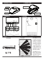
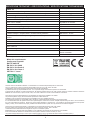
COMPLIANT
EN50131-2-2:2008
SMILE 18
Sensore infrarosso
pir detector
DETECTEUR INFRAROUGE
Installazione
installation
INSTALLATION
Italiano
1. Introduzione
SMILE 18 è un sensore ad infrarosso passivo con un sistema di calcolo dell’amplificazione del segnale
(piroelettrico a 2 elementi) con copertura in lunghezza di oltre 15 mt e in larghezza di 90°, garantendo
un’assoluta sicurezza contro i falsi allarmi. La qualità delle soluzioni elettroniche fanno dello SMILE 18 un
apparecchio affidabile, sia per la robustezza che per il funzionamento, anche in condizioni particolari (caldo eccessivo, umidità eccessiva). L’ingegnerizzazione meccanica è stata realizzata in modo tale da non
utilizzare viti, sia per il fissaggio della scheda all’interno della cover che per l’apertura del sensore stesso.
Per accedere alla scheda elettronica sarà sufficiente fare pressione su un tasto sul fondo della cover (vedi
figura) e, facendo leva sui blocchetti in ABS, si potrà estrarre la scheda elettronica e lavorare in piena libertà. Grazie all’ingresso di BLOCCO SENSORE (B/S) è possibile attivare e disattivare completamente il
sensore (led compreso).
2. Installazione
- Utilizzando uno strumento sottile (esempio mini cacciavite a taglio), spingere il tastino tondo sul lato anteriore del sensore (figura 1) e aprire la cover.
- rimuovere la scheda elettronica dal fondo della cover facendo leva sulla clips lato morsetti (fig.2)
- forare gli sfondabili che si desidera utilizzare per il fissaggio, oppure utilizzare l’apposito snodo (opzionale).
Altezza consigliata per il fissaggio 2m.
- fare scorrere il cavo di collegamento attraverso l’apposita guida sul retro della cover facendolo uscire dal
foro in alto.
- cablare il circuito seguendo la guida ai collegamenti (figura 3).
NB: in fase di chiusura del rivelatore, porre particolare attenzione affinchè la molla del contatto
tamper si posizioni correttamente nella sede conica ricavata sul frontale dello stesso.
ATTENZIONE: Non oscurare parzialmente o totalmente il campo di visione del rivelatore.
3. Collegamento e regolazione
Per il collegamento alla centrale fare riferimento allo schema (fig. 3).
Per disabilitare completamente il led walk test si può aprire il jumper LED (fig. 4)
Se invece si desidera disabilitare completamente il sensore (led compreso) quando la centrale è disattivata,
fornire una tensione 13.8Vcc sul morsetto B/S .
Nella fig. 3 è mostrato un esempio di disabilitazione del sensore a centrale disarmata. Utilizzare una resistenza da 1KΩ e collegarla ad un’uscita OPEN-COLLECTOR e programmare la stessa per chiudere a
negativo ad impianto armato.
english
1. introduction
SMILE 18 is a 2-element passive IR detector. The processing of the signal generated by the PIR is able to
ensure a coverage of 15 m at a horizontal angle of 90°, assuring an absolute immunity to false alarms. The
quality of the electronic solutions make it a very reliable detector, both for its solidity and for its functionality,
even in particular conditions (extreme heat or humidity). The housing does not require any screws neither
to fasten the electronic board to the base nor to open the detector. To disassemble the detector just press
the tooth on the bottom of the case (see figure) and pull out the PCB by pushing the clip and by levering
on the ABS supports (see figure). In this way it will be possible to freely work on the PCB. Thanks to the
terminal BLOCK SENSOR (B/S) it is possible to activate and disable the Walk Test LED without opening
the housing.
www.amcelettronica.com
Installation Instructions v1.1
SMILE 18 Pir Detector
1
2. installation procedure
- By using a thin screwdriver, push the round tooth on the bottom and open the housing (see figure 1)
- Remove the PCB from the base (figure 2) by levering on the ABS supports (see figure 2)
- Use a screwdriver to pierce the knockouts on the side of the base where you wish to attach the detector to
the wall or use the optional swivel bracket. (height 2m)
- Route the wires via the rear channel into the base and let them pass through the hole on the top of the
housing (see figure)
- Wire up the terminals following the connections shown in figure 3.
WARNING: closing the detector’s cover, check that the tamper’s spring fits in conical seat in the
cover.
CAUTION: Do not partially or totally obscure the field of view of the detector.
3. CONNECTIONS AND settings
As for the connections with the control unit please refer to figure 3.
To disable the LED WALK TEST open the jumper LED (fig. 4).
Instead, if you want to disable completely the detector (led included) only when the control unit isn’t armed,
apply a voltage 13.8 Vdc at terminal B/S.
In figure 3 is shown a detector disable when the control unit is disarmed.
Use a 1 KΩ resistor to connect to a system status open collector output, that gives a ground voltage when
the control unit is armed.
FRANÇAIS
1. INTRODUCTION
Le SMILE 18 est un détecteur infrarouge passif avec un système de calcul de l’amplification du signal (pyroélectrique à deux éléments) avec une portée de 15m et un angle de couverture de 90° garantissant une
protection optimale contre les déclenchements intempestifs. La qualité des solutions techniques font du
SMILE 18 un détecteur extrêmement fiable pour tout type d’installation et ce même dans des conditions
particulières (longueur de cable excessive, locaux humides). La conception mécanique a été réalisée de
telle façon à ne pas utiliser de vis pour la fixation de la platine électronique à l’intérieur du détecteur et pour
l’ouverture du capot du SMILE 18.
2 INSTALLATION
Pour l’installation, ouvrir le détecteur en pressant sur le petit clip se trouvant dans la partie inférieure à l’aide
d’un petit tournevis (voir fig1) puis déclipser la platine électronique (voir fig 2). Défoncer les pré-percements
ou utiliser une rotule suivant le type d’installation puis faire sortir le cable de raccordement dans la partie
supérieure et fixer le fond. En phase de fermeture du détecteur , faire attention que le ressort du contact
tamper soit positionné correctement dans le logement conique qui se trouve sur le couvercle.
ATTENTION: Ne pas occulter partiellement ou totalement le champ de vision du détecteur.
3 CABLAGE ET REGLAGE
Pour le raccordement, se référer à la fig.3
Pour désactiver la led de test, retirer le cavalier LED
Pour désactiver le détecteur, fournir une tension +12v à la borne B/S
On peut aussi désactiver le détecteur en cablant une résistance entre le +12v et la borne B/S et en fournissant une tension de -12v à la borne B/S (voir fig.3)
www.amcelettronica.com
SMILE 18 Pir Detector
2
Installation Instructions v1.1
1. General view
2. Inside view
Sfondabili per fissaggio
Mounting knockouts
Led WALK TEST
Lente / Lens
Premere qui per aprire
Press here to open
Fissaggio circuito
Clip for electronic board
3. TERMINALS
4. board
CENTRALE
CONTROL PANNEL
13.8VDC
+
24H
OPEN
COLLECTOR
ALARM
ARM/DISARM CONTACT
-
1K
JUMPER LED
SUPPLY
ALIMENTAZIONE
SUPPLY
13.8
TAMPER
B/S
TAMPER
STOP
WALK
TEST
N.C.
ALLARME
ALARM
5. lens
AMC SMILE 18 permette
una copertura di 15 mt,
la speciale conformazione della lente permette
un’apertura orizzontale
di oltre 90° con 29 fasci
su 5 livelli (5 antiavvicinamento,6 a corta portata, 7 a media portata, 6
a media-lunga portata, 5
a lunga portata).Si raccomnda di non oscurare
ne parzialmente ne completamente il campo di
visione del rivelatotre.
AMC SMILE 18 allows a
range of 15 mt, the special lens shape provides
a horizontal coverage of
more than 90° with 29
patterns on 5 levels.
www.amcelettronica.com
SMILE 18 Pir Detector
3
Installation Instructions v1.1
Specifiche tecniche / specifications / SPECIFICATIONS TECHNIQUES
SMILE 18
Alimentazione / Input Voltage / Alimentation
Consumo / Current Drain / Consommation - Alarm/Stand-By
Portata in lunghezza / Coverage / Portee
Portata in larghezza / Angle / Angle de couverture
Piroelettrico / PIR / Pyroelettrique
Lente / Lens / Lentille
Durata allarme / Alarm period /Duree alarme
Antiapertura / Anti-opening / Autoprotection
Antistrisciamento / Creep zone / Detection sous le detectour
Contatto di allarme / Alarm contact / Contact d’alarme
Contatto di tamper / Tamper switch / Contatct d’auto-protection
9 to 15 Vcc
(18 mA/9.5mA) @ 13.8 Vcc
15 mt
90°
2 elementi / 2 elements
29 patterns on 5 levels
4 sec.
✔
✔
0.2 A - 24 Vcc
Max 40 mA - 30 Vcc
Temperatura di esercizio / Operating temperature / Temperature de fonction- From -10 °C to +55 °C
nement
Temperatura di stoccaggio / Storage temperature / Temperature de stockage
From -20 °C to 60 °C
RFI Protezione / Protection / Protection
10 V / m (20 MHz - 2000 MHz)
✔
✔
ABS
Snodo orientabile / Swivel bracket /
Rotule orientable*
110 x 60 x 46 mm
Led WALK TEST
WALK TEST IN
Cover / Housing / Boiter
Accessori / Accessories / Accessoires
Dimensioni / Dimensions
*: Non coperto da omologazione IMQ.
Meets the requirements:
Conforme ai requisiti:
R&TTE 99/5/CE
EN 50131-2-2: 2008
EN 50131-2-2 Grade 2
EN 50131-2-2 Class 2
CEI 79-2: I° Level
Prodotto conforme alla Direttiva 99/5/CE. La dichiarazione di conformità è disponibile presso la nostra sede.
Tutti i ns. prodotti sono conformi ai requisiti richiesti dalla norma CEI 79-2 2°ed. 1998 + Ab 2000.
L’installazione deve essere eseguita a regola d’arte da personale specializzato.
Il produttore declina ogni responsabilità nel caso in cui il prodotto venga manomesso da persone non autorizzate.
Si raccomanda di verificare il corretto funzionamento del sistema d’allarme almeno una volta al mese, tuttavia un sistema di allarme elettronico
affidabile non evita intrusioni, rapine, incendi o altro, ma si limita a diminuire il rischio che tali situazioni si verifichino.
This product comply the 99/5/CE directive. The declaration of conformity is available at our offices.
Our products/systems comply with the essential requirements of EEC directives.
Installation must be carried out following the local installation norms by qualified personnel.
The manufacturer refuses any responsibility when changes or unauthorized repairs are made to the product/system.
It is recommended to test the operation of the alarm product/system at least once a month. Despite frequent testing and due to, but not limited to,
any or all of the following: tampering, electrical or communication disruption or improper use, it is possible for the product/system to fail to prevent
burglary, rubbery, fire or otherwise. A properly installed and maintained alarm system can only reduce the risk that this happens.
Produit conforme à la Directive 99/5/CE. La déclaration de conformité est disponible chez notre société.
Tous nos produits sont conformes aux requises prévu par la norme CEI 79-2°ed. 1998 + Ab 2000.
L’installation doit ètre effectuée dans les règles de l’art par un installateur qualifié.
AMC Elettronica S.r.l. décline toute responsabilité en cas d’utilisation des produits par des personnes non habilitées.
Il est recommandé de vérifier le bon fonctionnement du système d’alarme au moins une fois par mois.
Un système d’alarme électronique n’exclut pas le risque d’intrusion, de vol, d’incendie mais limite et diminue fortement celui-ci
www.amcelettronica.com
SMILE 18 Pir Detector
4
Installation Instructions v1.1


![[User manual] - KX_series_user_EN](http://vs1.manualzilla.com/store/data/005985322_1-73e2348e6003cbf1e0abe0da04f5dcec-150x150.png)