1
PV-IB _Eng_IT_Hyoshi 08.3.6 9:49 ページ1
!!
PV-IB-Italian 08.3.6 10:02 ページ1
Italiano
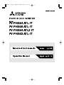
INVERTER FOTOVOLTAICO
MODELLO
PV-PNS04ATL-IT
PV-PNS06ATL-IT
PV-PNS04ATL2-IT
PV-PNS03ATL-IT
Manuale di funzionamento
per gli utenti.
●Leggere con attenzione questo manuale per utilizzare l’inverter fotovoltaico
(inverter PV) in modo corretto e sicuro. Si prega di prestare particolare attenzione alla sezione “Precauzioni di sicurezza” prima di usare l’inverter PV.
●Il manuale dovrebbe essere sempre a disposizione dell’operatore dell’inverter PV.
L’inverter PV-PNS04ATL-IT / PV-PNS06ATL-IT / PV-PNS04ATL2-IT / PV-PNS03ATLIT è progettato in base alle normative definite dalla DK 5940. Pertanto, il proprietario può usare l’inverter PV solo nei paesi o nelle aree nelle quali queste normative sono in vigore.
PV-IB-Italian 08.3.6 10:02 ページ2
Sommario
Pagina
Presentazione •
• • • • • • • • • • • • • • • • • • • • • • • • • • • • • • • • • • • • • • • • • • • • •
4
1 Precauzioni di sicurezza • • • • • • • • • • • • • • • • • • • • • • • • • • • • • • • • • • 5∼7
2 Norme applicabili • • • • • • • • • • • • • • • • • • • • • • • • • • • • • • • • • • • • • • • • • • 8
3 Configurazione del sistema PV
• • • • • • • • • • • • • • • • • • • • • • • • • • • •
9∼10
4 Parti e nomi rispettivi • • • • • • • • • • • • • • • • • • • • • • • • • • • • • • • • • • • 11∼12
4.1 Aspetto • • • • • • • • • • • • • • • • • • • • • • • • • • • • • • • • • • • • • • • • • • • • 11
4.2 Schermo e pulsanti•
4.3 Passacavi • • • • • • •
5 Funzionamento •
• • • • • • • • • • • • • • • • • • • • • • • • • • • • • • • • • • •
• • • • • • • • • • • • • • • • • • • • • • • • • • • • • • • • • • •
• • • • • • • • • • • • • • • • • • • • • • • • • • • • • • • • • • • • • •
11
12
13∼40
5.1 Procedura di funzionamento • • • • • • • • • • • • • • • • • • • • • • • • • 13∼14
5.1.1 Avvio (accensione) • • • • • • • • • • • • • • • • • • • • • • • • • • • • • • • • 13
5.1.2 Stop (spegnimento)
• • • • • • • • • • • • • • • • • • • • • • • • • • • • • • •
5.2 Verifica dello stato operativo
• • • • • • • • • • • • • • • • • • • • • • • • •
14
15∼18
5.2.1 Schermo LCD e LED • • • • • • • • • • • • • • • • • • • • • • • • • • • 15∼17
5.2.2 Accensione del LED di errore • • • • • • • • • • • • • • • • • • • • • • • • 18
5.3 Verifica dei dati operativi
• • • • • • • • • • • • • • • • • • • • • • • • • • • •
5.3.1 Selezione dell’elemento a schermo
• • • • • • • • • • • • • • • •
19∼40
19∼21
5.3.2 Descrizione degli elementi a schermo• • • • • • • • • • • • • • • 22∼26
5.3.3 Impostazione di data e ora • • • • • • • • • • • • • • • • • • • • • • • • • • 27
5.3.4 Impostazione della lingua • • • • • • • • • • • • • • • • • • • • • • • • • • • 28
5.3.5 Impostazione del prezzo unitario • • • • • • • • • • • • • • • • • • • • • • 29
5.3.6 Modalità AUTO TEST • • • • • • • • • • • • • • • • • • • •
5.3.7 Impostazione del numero di indirizzo -Interfaccia
• • • • • •
30∼37
RS485 con dispositivo esterno • • • • • • • • • • • • • • • • • • • 38∼39
5.3.8 Procedura di impostazione per interfaccia RS485
con invertitori multipli • • • • • • • • • • • • • • • • • • • • • • • • • • • • • • 40
6 Manutenzione •
• • • • • • • • • • • • • • • • • • • • • • • • • • • • • • • • • • • • • • •
41∼46
6.1 Operazioni di manutenzione giornaliera • • • • • • • • • • • • • • • • • 41∼43
6.2 Verifiche quotidiane • • • • • • • • • • • • • • • • • • • • • • • • • • • • • • • • • • • 44
6.3 Guasti•
• • • • • • • • • • • • • • • • • • • • • • • • • • • • • • • • • • • • • • • • •
2
45∼46
PV-IB-Italian 08.3.6 10:02 ページ3
7 Dati tecnici •
• • • • • • • • • • • • • • • • • • • • • • • • • • • • • • • • • • • • • • • • •
47∼52
7.1 Specifiche • • • • • • • • • • • • • • • • • • • • • • • • • • • • • • • • • • • • • • • 47∼49
7.2 Impostazioni• • • • • • • • • • • • • • • • • • • • • • • • • • • • • • • • • • • • • • • • • 50
9 Registrazione dell’energia generata •
3
• • • • • • • • • • • • • • • • • • • • • • •
54∼55
Italiano
7.3 Codici di errore • • • • • • • • • • • • • • • • • • • • • • • • • • • • • • • • • • • 51∼52
8 Glossario • • • • • • • • • • • • • • • • • • • • • • • • • • • • • • • • • • • • • • • • • • • • • • • 53
PV-IB-Italian 08.3.6 10:02 ページ4
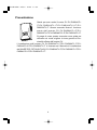
Presentazione
Grazie per aver scelto l’inverter PV PV-PNS04ATLIT/PV-PNS06ATL-IT/PV-PNS04ATL2-IT/PVPNS03ATL-IT. Questo manuale illustra il funzionamento dell’inverter PV PV-PNS04ATL-IT/PVPNS06ATL-IT/PV-PNS04ATL2-IT/PV-PNS03ATL-IT.
Si prega di usare questo manuale come guida per
utilizzare nel modo migliore la ricca gamma di funzionalità offerte dall’inverter PV.
L’installazione dell’inverter PV PV-PNS04ATL-IT/PV-PNS06ATL-IT/PVPNS04ATL2-IT/PV-PNS03ATL-IT è illustrata nel “Manuale di installazione
dell’INVERTER FOTOVOLTAICO PV-PNS04ATL-IT/PV-PNS06ATL-IT/PVPNS04ATL2-IT/PV-PNS03ATL-IT”.
4
PV-IB-Italian 08.3.6 10:02 ページ5
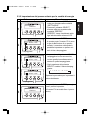
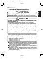
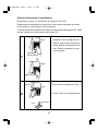
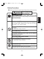
1 Precauzioni di sicurezza
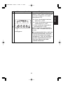
●I seguenti simboli denotano il tipo e il grado di pericolo che può derivare
da un uso errato del dispositivo.
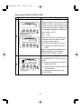
Prima di lavorare sull’inverter PV, premere sempre il
pulsante POWER dell’inverter PV per interrompere
Importante l’esecuzione. Disattivare entrambi gli interruttori AC e DC.
In caso contrario l’utente può subire scosse elettriche.
Non lasciare incustodito un inverter PV guasto.
Se si rilevano odori anomali o fumi, per prima cosa disattivare
immediatamente l’apparecchiatura usando il pulsante POWER.
In secondo luogo, disattivare entrambi gli interruttori AC e DC Quindi,
contattare il rivenditore.
Non usare l’inverter PV per finalità difformi dalla
generazione di PV.
In caso contrario possono svilupparsi incendi e l’utente può subire
lesioni.
Proibito
Non ispezionare personalmente l’inverter PV.
In caso contrario l’utente può subire scosse elettriche.
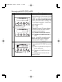
Non collocare o inserire oggetti metallici o liquidi nelle
aperture di ventilazione dell’inverter PV.
In caso contrario l’utente può subire scosse elettriche.
Non salire sull’inverter PV né aggrapparsi ad esso.
L’unità può cadere e provocare lesioni.
Non smontare o modificare l’inverter PV.
In caso contrario possono svilupparsi incendi e l’utente può subire
lesioni.
Non smontare o
modificare
Non toccare l’inverter PV durante un temporale o in caso di
calamità naturali.
In caso contrario l’utente può subire scosse elettriche.
Non toccare Non aprire il pannello anteriore dell’inverter PV.
Toccando le parti interne dell’inverter PV l’utente può subire scosse elettriche.
5
Italiano
AVVERTENZA
Avverte del possibile pericolo di morte
o di lesioni gravi che si può correre
utilizzando l’inverter PV in modo errato.
PV-IB-Italian 08.3.6 10:02 ページ6
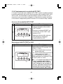
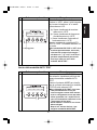
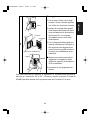
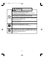
ATTENZIONE
Avverte di possibili lesioni o danni
all’edificio o agli oggetti dell’abitazione
che possono verificarsi se si utilizza
l’inverter PV in modo errato.
Non collocare alcun oggetto sull’inverter PV.
Non ostruire l’apertura di ventilazione dell’inverter PV.
In caso contrario possono svilupparsi incendi e l’utente può subire
lesioni.
Non esporre l’inverter PV a getti di aria fredda o di vapore.
L’accumulo di brina potrebbe causare problemi di alimentazione o
cortocircuiti.
Proibito
Non utilizzare l’inverter PV nei pressi di attrezzature ad alta
frequenza quali ad esempio i walkie-talkie.
Un errore di captazione del segnale potrebbe portare a un cortocircuito.
Non pulire l’inverter PV con un panno umido.
In caso contrario l’utente può subire scosse elettriche.
Indossare i guanti di protezione quando si pulisce l’inverter
PV.
Spigoli vivi come quelli delle aperture di ventilazione possono
Importante provocare lesioni.
Non toccare le aperture di ventilazione dell’inverter PV o le
zone circostanti durante il funzionamento o nei momenti
immediatamente successivi allo spegnimento. La
Non toccare temperatura delle superfici in questione può superare i 60°C.
Si possono verificare ustioni.
6
PV-IB-Italian 08.3.6 10:02 ページ7
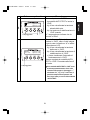
ATTENZIONE
・All’esterno, o in luoghi analoghi (※È PROIBITA l’installazione dell’inverter
PV in luoghi che non possono essere separati da ambienti esterni, quali
ad esempio rimesse aperte su un lato e sprovviste di pareti o porte in
grado di bloccare l’apertura).
・Luoghi nei quali il dispositivo può essere esposto a luce solare diretta.
・Luoghi angusti e privi di ventilazione.
・Luoghi nei quali il dispositivo è esposto al contatto con l’acqua
・Luoghi nei quali l’umidità sia elevata in modo significativo, quali ad esempio le lavanderie o i bagni
・Luoghi nei quali sia presente una quantità eccessiva di vapore, vapori d’olio, fumo, polvere o sostanze corrosive
・Luoghi nei quali il dispositivo può essere esposto a fumi oleosi, quali ad
esempio le cucine.
・Luoghi nei quali sono presenti gas infiammabili o esplosivi.
・Luoghi nei quali le installazioni sono vulnerabili alle vibrazioni o agli urti.
・Luoghi nelle vicinanze di materiali infiammabili
・Luoghi con condizioni inusuali e diverse da quelle indicate in precedenza
(quali ad esempio a bordo di imbarcazioni o veicoli a motore)
・Luoghi nei quali si possono subire danni da aria salmastra
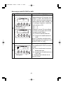
Nota
Evitare di installare l'inverter PV nei seguenti luoghi:
(In caso contrario, l'inverter PV potrebbe indurre gli elettrodomestici a
generare disturbi).
・Luoghi nei quali i disturbi o i disturbi di natura elettrica sono strettamente
controllati
・Luoghi nei pressi di cavi e antenne radio-televisive
7
Italiano
Evitare di installare l’inverter PV nei seguenti luoghi:
(In caso contrario, l’inverter PV può subire guasti oppure può risultare
impossibile usarlo in modo sicuro; inoltre, la garanzia del prodotto può
risultare invalidata).
PV-IB-Italian 08.3.6 10:02 ページ8
2 Norme applicabili
L’inverter PV si conforma alle regole e alle normative indicate da LVD, EMC e
CE. Inoltre si conforma alle normative definite nella EN, CEI 11-20 e nella DK
5940. L’inverter PV, infine, soddisfa le disposizioni definite in relazione alla
compatibilità elettromagnetica (EMC) e alla direttiva per le basse tensioni
(LVD) certificata nella dichiarazione CE.
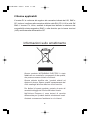
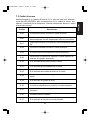
Informazioni sullo smaltimento
Questo prodotto MITSUBISHI ELECTRIC è stato
fabbricato con materiali e componenti di alta qualità,
che possono essere riciclati e riutilizzati.
Questo simbolo significa che i prodotti elettrici ed
elettronici devono essere smaltiti separatamente dai
rifiuti casalinghi alla fine della loro vita di servizio.
Per disfarsi di questo prodotto, portarlo al centro di
raccolta/riciclaggio dei rifiuti solidi urbani locale.
Nell’Unione Europea ci sono sistemi di raccolta
differenziata per i prodotti elettrici ed elettronici usati.
Aiutateci a conservare l’ambiente in cui viviamo!
8
PV-IB-Italian 08.3.6 10:02 ページ9
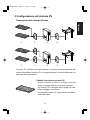
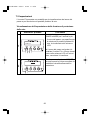
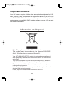
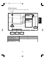
3 Configurazione del sistema PV
Panoramica del sistema di base
Italiano
①
②
③
④
①
②
③
④
L’inverter PV converte l’energia elettrica a corrente continua generata dal
modulo fotovoltaico (modulo PV) in energia elettrica a corrente alternata e la
trasmette alla rete elettrica.
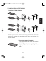
① Modulo fotovoltaico (modulo PV)
Questo modulo converte l’energia luminosa
solare in energia elettrica a corrente continua.
Un modulo PV è composto da un gruppo di celle
solari collegate l’una all’altra.
Un gruppo di moduli PV viene definito una batteria di celle solari.
9
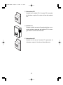
PV-IB-Italian 08.3.6 10:02 ページ10
② Interruttore DC
Inserito tra il modulo PV e l’inverter PV, permette
di chiudere o aprire il circuito sul lato del modulo
PV.
③ Inverter PV
Questo modulo converte l’energia elettrica a corrente continua generata dal modulo PV in energia elettrica a corrente alternata.
④ Interruttore AC
Inserito tra la rete e l’inverter PV, permette di
chiudere o aprire il circuito sul lato della rete.
10
PV-IB-Italian 08.3.6 10:02 ページ11
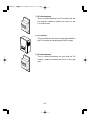
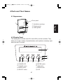
4 Parti e nomi rispettivi
Italiano
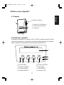
4.1 Aspetto
Pannello anteriore
①
①
②
① Aperture di ventilazione
② Schermo del pannello
③ Passacavi
③
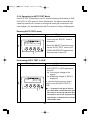
4.2 Schermo e pulsanti
Il dispositivo presenta uno schermo LCD, tre LED e quattro pulsanti. Questi
comandi consentono di visualizzare una varietà di dati operativi e di eseguire
tutte le operazioni necessarie al funzionamento dell’inverter PV.
⑧
⑦
⑥
①
②
③
④
⑤
① LED POWER
⑤ Pulsante ENTER
② Pulsante POWER
⑥ LED GRID
③ Pulsante MODE
⑦ LED ERROR
④ Pulsante SELECT
⑧ Schermo LCD
11
PV-IB-Italian 08.3.6 10:02 ページ12
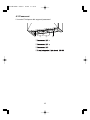
4.3 Passacavi
L’inverter PV dispone dei seguenti passacavi.
④
①
②
③
④
①
②
③
12
PV-IB-Italian 08.3.6 10:02 ページ13
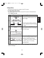
5 Funzionamento
Quanto segue illustra il funzionamento dell’inverter PV.
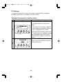
5.1 Procedura di funzionamento
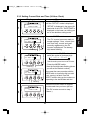
5.1.1 Avvio (accensione)
Schermo e pulsanti
Procedura
Quando l’inverter PV è inattivo, premere e tenere premuto il pulsante
POWER per due secondi o più.
・L’inverter PV si avvia: il “cancello”
visualizzato sull’LCD inizia ad aprirsi.
1
Lo schermo LCD mostra la scritta
“AVVIO” per 3 secondi e quindi passa
alla modalità STATUS.
AVV I O
2
ATTENDERE PREGO
1 2 3 4 5 kWh
(Per: preparazione per l’esecuzione)
3
Successivamente lo schermo LCD
mostra informazioni quali i messaggi, lo
stato della generazione di energia eletI N F UNZ I ONE
trica, l’energia totale generata, ecc.,
1 2 3 4 5 kWh
disponibili nelle sue varie modalità di
(Per: esecuzione con la rete collegata) funzionamento.
Per ulteriori dettagli, fare riferimento a
“5.2 Verifica dello stato operativo” .
Dopo aver attivato l’inverter PV, questo funziona automaticamente sulla
base della quantità di luce solare ricevuta.
13
Italiano
La procedura di funzionamento per l’avvio e lo stop dell’inverter PV è illustrata qui sotto.
PV-IB-Italian 08.3.6 10:02 ページ14
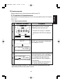
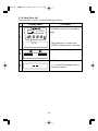
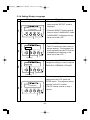
5.1.2 Stop (spegnimento)
Per interrompere il funzionamento dell’inverter PV, usare la procedura
seguente.
Schermo e pulsanti
I N FUNZ I ONE
1 2 3 4 5 kWh
1
STOP
2
Procedura
Quando l’inverter PV è in esecuzione,
premere e tenere premuto il pulsante
POWER per due secondi o più.
・Questo interrompe il funzionamento
dell’inverter PV: il messaggio
“STOP” viene visualizzato per 3
secondi.
Il “cancello” inizia a chiudersi sullo
schermo LCD.
L’inverter PV interrompe l’esecuzione.
3
・Il messaggio “----” visualizzato sullo
schermo LCD indica che l’inverter
PV è inattivo.
14
PV-IB-Italian 08.3.6 10:02 ページ15
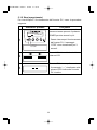
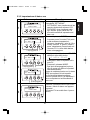
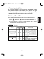
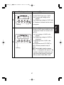
5.2 Verifica dello stato di funzionamento
5.2.1 Verifica dello schermo LCD e dei LED
Ogni stato operativo visualizzato sullo schermo LCD e sui LED è elencato
qui sotto.
※ LED:
Inattività.
indica Attività,
indica lampeggiamento, e
indica
※ Un valore numerico che rappresenta l’energia generata in kWh compare sul lato destro dello schermo LCD.
STOP
(spegnimento)
LCD
LED
POWER GRID ERROR
Descrizione
Lo schermo LCD e tutti i LED
sono inattivi durante i momenti
in cui (1) la luce solare è minima, ad esempio di notte,
oppure (2) l’interruttore DC è in
posizione di disattivazione.
Questo avviene perché l’alimentatore dell’inverter PV
viene disattivato in queste circostanze.
(Lo schermo è inattivo)
L’inverter PV ha “interrotto”
l’esecuzione.
La pressione del pulsante
POWER avvia l’esecuzione
dell’inverter PV.
15
Italiano
L’inverter PV visualizza il proprio stato di funzionamento sullo schermo LCD e sui LED in base alle sue effettive condizioni operative.
Schermo LCD e LED sono inattivi durante la notte o nei momenti in
cui la luce solare è minima. Questo avviene perché l’alimentatore dell’inverter PV viene disattivato in queste circostanze.
PV-IB-Italian 08.3.6 10:02 ページ16
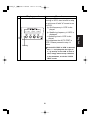
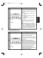
<Attesa> (accensione)
RUN
LCD
LED
POWER GRID ERROR
L’inverter PV è nella fase di
preparazione alla generazione dell’energia. L’inverter PV inizia l’esecuzione.
ATTENDERE PREGO
1 2 3 4 5 kWh
Il livello di irradiazione è temporaneamente calato. L’inverter PV è in
stato di standby sino al ritorno dell’irradiazione a un livello predefinito.
BASSA POTE NZA
1 2 3 4 5 kWh
Dato che l’irradiazione è insufficiente,
l’inverter PV evita l’esecuzione in
modalità con rete collegata.
Si è verificato un blackout oppure
l’interruttore AC è in posizione OFF.
BLACKOUT
1 2 3 4 5 kWh
La funzione di protezione della
rete è attiva. L’inverter PV è in
stato di standby, in attesa del
ripristino della rete al suo livello
normale.
NON CONNESSO
1 2 3 4 5 kWh
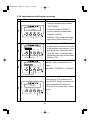
Lampeggiante
STANDBY
Descrizione
La funzione di protezione della
rete è attiva. Il valore numerico
sul lato superiore destro dello
schermo LCD indica il tempo in
secondi che deve trascorrere
prima che l’inverter PV riprenda
la generazione di energia elettrica.
20sec
1 2 3 4 5 kWh
16
PV-IB-Italian 08.3.6 10:02 ページ17
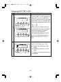
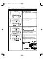
<Generazione>
RUN
LCD
LED
POWER GRID ERROR
Descrizione
I N F UN Z I ONE
1 2 3 4 5 kWh
ERROR
LCD
LED
POWER GRID ERROR
Si è verificato un guasto nella
rete o nel sistema di generazione PV; il guasto ha attivato
il dispositivo di sicurezza integrato. Il codice [E-**](dove ** è
un numero a due cifre) nel lato
superiore destro è un codice di
errore. Per una spiegazione del
suo significato, vedere p.51
“Codici di errore”.
(Tipico)
E RROR E
Descrizione
E - 24
1 2 3 4 5 kWh
Se il LED ERROR è acceso, seguire la procedura descritta a p.18
“Accensione del LED di errore”.
17
Italiano
Il dispositivo sta generando
energia elettrica. La barra di
alimentazione sul lato inferiore
sinistro dello schermo LCD
indica l’energia generata nell’occasione.
PV-IB-Italian 08.3.6 10:02 ページ18
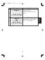
5.2.2 Accensione del LED di errore
Se il LED ERROR è illuminato, procedere come segue.
Schermo e pulsanti
Procedura
1. Premere il pulsante POWER per 2
secondi o più. Questo interrompe
l’esecuzione dell’inverter PV.
2. Accertarsi che sia visualizzato il
messaggio “----”, quindi premere
nuovamente il pulsante POWER
per due secondi o più. Questo
avvia l’inverter PV.
Se la procedura illustrata qui sopra non risolve il problema (cioè se il LED
ERROR si accende di nuovo), procedere come segue.
Schermo e pulsanti
Procedura
1. Premere il pulsante POWER per 2
secondi o più. Questo interrompe
l’esecuzione dell’inverter PV.
2. Portare in posizione OFF l’interruttore DC.
3. Portare in posizione OFF l’interruttore AC.
4. Contattare il rivenditore per le
riparazioni.
18
PV-IB-Italian 08.3.6 10:02 ページ19
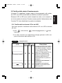
5.3 Verifica dei dati operativi
5.3.1 Selezione dell’elemento a schermo
(1) Dati operativi correnti: potenza di uscita, tensione di ingresso, tensione
della rete, corrente di uscita, (di oggi) potenza massima di uscita, data e
ora
(2) Dati cumulativi: energia totale generata, importo, riduzione di CO2, ore
di funzionamento
(3) Dati operativi giornalieri: energia generata oggi, importo, riduzione di
CO2, ore di funzionamento, energia generata ieri
(4) Dati operativi mensili: energia generata questo mese, importo, riduzione
di CO2, ore di funzionamento, energia generata lo scorso mese
(5) Dati operativi annuali: energia generata quest’anno, importo, riduzione
di CO2, ore di funzionamento, energia generata l’anno scorso
Inoltre, l’operatore può impostare informazioni pertinenti agli elementi quali
data e ora mentre li visualizza sullo schermo LCD.
L’operatore può passare da un elemento all’altro azionando i pulsanti
MODE o SELECT.
Tuttavia, lo schermo torna alla visualizzazione di STATUS se l’operatore
lascia passare 30 secondi o più senza intervenire sui dati operativi visualizzati.
19
Italiano
Oltre allo stato operativo illustrato nella sezione 5.2, l’operatore può utilizzare lo schermo LCD per sorvegliare numerosi dati operativi.
PV-IB-Italian 08.3.6 10:02 ページ20
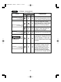
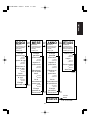
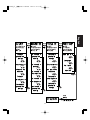
La tabella seguente illustra le relazioni esistenti tra le modalità e gli elementi a schermo.
È possibile selezionare ogni modalità
premendo il pulsante MODE.
È possibile selezionare la voce sotto ogni
modalità premendo il pulsante SELECT.
STATUS
AVVIO
Premere
MODE
ATTUALE
IN FUNZIONE
BASSA
POTENZA
TOTALE
(Modalità di
visualizzazione del
valore corrente)
Vedere p.22
(Modalità di
visualizzazione del
valore cumulativo
complessivo)
Vedere p.23
Potenza di
uscita
Energia totale
generata
Premere
Tensione di
ingresso
↓SELECT
Importo totale
Premere
↓SELECT
Premere
↓SELECT
Riduzione di
CO2 totale
Tensione
della rete
Premere
↓SELECT
Corrente di
uscita
Premere
↓SELECT
Ore totali di
funzionamento
Premere
↓SELECT
BLACKOUT
Potenza
massima di uscita
Premere
↓SELECT
NON CONNESSO
Data e ora
STANDBY
ERRORE
20
Premere
MODE
Premere
↓SELECT
STOP
ATTENDERE
PREGO
Premere
MODE
Premere
SELECT
Premere
SELECT
PV-IB-Italian 08.3.6 10:02 ページ21
Italiano
OGGI
(Modalità di
visualizzazione del
valore cumulativo
giornaliero)
Vedere p.24
Premere
MODE
Energia
generata oggi
(Modalità di
visualizzazione del
valore cumulativo
mensile)
Vedere p.25
Premere
MODE
Energia
generata
questo mese
Premere
↓SELECT
Riduzione di
CO2 di oggi
Ore di
funzionamento
di oggi
Premere
Premere
SELECT
Lingua
Premere
↓SELECT
Prezzo unitario
Premere
↓SELECT
Premere
Auto Test
Riduzione di
CO2 di
quest’anno
Premere
SELECT
Premere
Premere
↓SELECT
↓SELECT
Premere
↓SELECT
Riduzione di
CO2 di questo
mese
Premere
(Modalità di
visualizzazione
delle informazioni
dell’impostazione)
Vedere pp. 27-39
↓SELECT
Importo di
quest’anno
Premere
SETTAGGIO
Data e ora
Premere
↓SELECT
↓SELECT
(Modalità di visualizzazione del
valore cumulativo
annuale)
Vedere p.26
Press
MODE
↓SELECT
Importo di
questo mese
Premere
↓SELECT
ANNO
Energia
generata
quest’anno
Premere
↓SELECT
Importo di oggi
Energia
generata ieri
MESE
↓SELECT
Ore di
funzionamento
di quest’anno
Ore di
funzionamento di
questo mese
Premere
Premere
↓SELECT
↓SELECT
Energia
generata lo
scorso mese
Energia
generata lo
scorso anno
Premere
SELECT
Premere
SELECT
Premere
MODE
STATUS
21
A "STATUS"
PV-IB-Italian 08.3.6 10:02 ページ22
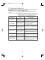
5.3.2 Descrizione degli elementi a schermo
I dati operativi visibili con l’aiuto degli elementi a schermo sono descritti qui sotto.
●ATTUALE (Modalità di visualizzazione del valore corrente)
ATTUAL E
Elemento a schermo
1. Premere il pulsante MODE diverse volte per visualizzare “ATTUALE” nel lato superiore sinistro
dello schermo LCD.
2. Premere il pulsante SELECT per visualizzare l’elemento voluto. Gli elementi compaiono nell’ordine
seguente.
LCD
Descrizione
ATTUALE 2 . 9 kW
POT . I N USC I TA
(Valore istantaneo) La potenza di uscita
viene visualizzata sul lato superiore destro.
(Numero intero a 2 cifre, 1 cifra decimale,
unità: kW)
Tensione di
ingresso
ATTUALE 4 5 2 . 2Vd c
TENS I ONE DC
(Valore istantaneo) La tensione di ingresso del modulo PV viene visualizzata sul lato superiore destro.
(Numero intero a 3 cifre, 1 cifra decimale, unità:
V c.c.)
Tensione della
rete
ATTUALE 2 3 0 . 2Va c
TENS I ONE D I RETE
(Valore istantaneo) La tensione della rete
viene visualizzata sul lato superiore destro.
(Numero intero a 3 cifre, 1 cifra decimale,
unità: V c.a.)
Corrente di uscita
ATTUALE 1 2 . 8Aa c
CORREN T E USC I TA
(Valore istantaneo) La corrente di uscita
viene visualizzata sul lato superiore destro.
(Numero intero a 3 cifre, 1 cifra decimale,
unità: A c.a.)
Potenza massima
di uscita
ATTUALE 3 . 0 kW
POT . MA X OD I ERNA
La potenza massima di uscita per la giornata corrente viene visualizzata sul lato superiore destro.
(Numero intero a 2 cifre, 1 cifra decimale, unità:
kW)
15 : 21 : 34
ORA
2 5 AGO 2 0 0 6
(Corrente) Ora, minuti e secondi sono
visualizzati sul lato superiore destro.
(Corrente) Giorno, mese e anno
sono visualizzati nella seconda riga.
Potenza di uscita
Data e ora
22
PV-IB-Italian 08.3.6 10:02 ページ23
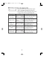
●TOTALE (Modalità di visualizzazione del valore cumulativo)
TOTALE
Elemento a schermo
LCD
Energia totale
generata
TOTALE 1 2 3 4 5 kWh
ENERG I A GENER A T A
L’energia totale generata viene visualizzata sul lato superiore destro.
(Numero intero a 5 cifre, unità: kWh)
Importo totale
TOTALE
5 3 6 0EUR
I MPOR TO
L’importo totale dell’energia elettrica venduta alla società produttrice di energia elettrica
viene visualizzata sul lato superiore destro.
(Numero intero a 5 cifre, unità: EUR)
totale
TOTAL E
2 1 8 5 k gC
R I DUZ I ONE CO2
La quantità totale di CO2 eliminata
dal sistema PV viene visualizzata sul
lato superiore destro.
(Numero intero a 5 cifre, unità: kgC)
Ore totali di funzionamento
TOTAL E 1 4 0 0 2 h r
OR E D I FUN Z I ONE
Le ore totali di funzionamento sono
visualizzate sul lato superiore destro.
(Numero intero a 5 cifre, unità: hr)
Riduzione di CO2
Descrizione
23
Italiano
1. Premere il pulsante MODE diverse volte per visualizzare “TOTALE” nel lato superiore sinistro dello
schermo LCD.
2. Premere il pulsante SELECT per visualizzare l’elemento voluto. Gli elementi compaiono nell’ordine
seguente.
PV-IB-Italian 08.3.6 10:02 ページ24
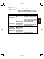
●OGGI (modalità di visualizzazione del valore giornaliero complessivo)
OGG I
1. Premere il pulsante MODE diverse volte per visualizzare “OGGI” nel lato superiore sinistro dello
schermo LCD.
2. Premere il pulsante SELECT per visualizzare l’elemento voluto. Gli elementi compaiono nell’ordine
seguente.
Elemento a schermo
LCD
Descrizione
Energia generata
oggi
OGG I
2 6 kWh
ENERG I A GENER A T A
L’energia generata oggi viene visualizzata sul lato superiore destro.
(Numero intero a 5 cifre, unità: kWh)
Importo di oggi
OGG I
I MPOR TO
L’importo dell’energia venduta oggi
viene visualizzata sul lato superiore
destro.
(Numero intero a 5 cifre, unità: EUR)
La riduzione di
CO2 di oggi
OGG I
5 k gC
R I DUZ I ONE CO2
La quantità totale di CO2 eliminata dal
sistema PV nella data corrente viene
visualizzata sul lato superiore destro.
(Numero intero a 5 cifre, unità: kgC)
Ore di funzionamento
di oggi
OGG I
10h r
OR E D I FUN Z I ONE
Le ore di funzionamento di oggi vengono visualizzate sul lato superiore
destro.
(Numero intero a 5 cifre, unità: hr)
Energia generata
ieri
OGG I
2 3 kWh
ENERG I A I ER I
L’energia generata ieri viene visualizzata sul lato superiore destro.
(Numero intero a 5 cifre, unità: kWh)
1 1EUR
24
PV-IB-Italian 08.3.6 10:02 ページ25
●MESE (Modalità di visualizzazione del valore cumulativo mensile)
MESE
Elemento a schermo
LCD
Descrizione
Energia generata
questo mese
MESE
2 9 7 kWh
ENERG I A GENER A T A
L’energia generata questo mese
viene visualizzata sul lato superiore
destro.
(Numero intero a 5 cifre, unità: kWh)
Importo di questo
mese
MESE
I MPOR TO
L’importo dell’energia venduta
questo mese viene visualizzata sul
lato superiore destro.
(Numero intero a 5 cifre, unità: EUR)
1 2 9EUR
La riduzione di
CO2 di questo
mese
MESE
5 3 k gC
R I DUZ I ONE CO2
La quantità totale di CO2 eliminata
dal sistema PV viene visualizzata sul
lato superiore destro.
(Numero intero a 5 cifre, unità: kgC)
Ore di funzionamento di questo
mese
MESE
300h r
OR E D I FUN Z I ONE
L’energia generata questo mese
viene visualizzata sul lato superiore
destro.
(Numero intero a 5 cifre, unità: hr)
MESE
2 8 5 kWh
OT T 2 0 0 6 ENERG I A
L’energia generata lo scorso mese
viene visualizzata sul lato superiore
destro.
(Numero intero a 5 cifre, unità: kWh)
Energia generata
lo scorso mese
25
Italiano
1. Premere il pulsante MODE diverse volte per visalizzare “MESE” nel lato superiore sinistro dello
schermo LCD.
2. Premere il pulsante SELECT per visualizzare l’elemento voluto. Gli elementi compaiono nell’ordine
seguente.
PV-IB-Italian 08.3.6 10:02 ページ26
●ANNO (Modalità di visualizzazione del valore cumulativo annuale)
ANNO
1. Premere il pulsante MODE diverse volte per visualizzare “ANNO” nel lato superiore sinistro dello
schermo LCD.
2. Premere il pulsante SELECT per visualizzare l’elemento voluto. Gli elementi compaiono nell’ordine
seguente.
Elemento a schermo
LCD
Descrizione
Energia generata
quest’anno
ANNO
3 2 1 8 kWh
ENERG I A GENER A T A
L’energia generata quest’anno viene
visualizzata sul lato superiore destro.
(Numero intero a 5 cifre, unità: kWh)
Importo di
quest’anno
ANNO
1 3 9 7EUR
I MPOR TO
L’importo dell’energia venduta
quest’anno viene visualizzato sul lato
superiore destro.
(Numero intero a 5 cifre, unità: EUR)
La riduzione di
CO2 di quest’anno
ANNO
5 7 0 k gC
R I DUZ I ONE CO2
La quantità totale di CO2 eliminata
dal sistema PV quest’anno viene
visualizzata sul lato superiore destro.
(Numero intero a 5 cifre, unità: kgC)
Ore di funzionamento
di quest’anno
ANNO
3650h r
OR E D I FUN Z I ONE
Energia generata
lo scorso anno
ANNO
3 3 0 2 kWh
2 0 0 5 ENERG I A
26
Le ore di funzionamento di quest’anno vengono visualizzate sul lato
superiore destro.
(Numero intero a 5 cifre, unità: hr)
L’energia generata lo scorso anno
viene visualizzata sul lato superiore
destro. Lo scorso anno di calendario
viene visualizzato sul lato inferiore
sinistro.
(Numero intero a 5 cifre, unità: kWh)
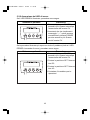
PV-IB-Italian 08.3.6 10:02 ページ27
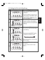
5.3.3 Impostazione di data e ora
Schermo e pulsanti
Lampeggiante
・A questo punto l’inverter PV è pronto ad accettare impostazioni.
Vengono visualizzati i valori di “Ora,
minuti, secondi” e “giorno, mese e
anno” attualmente memorizzati nell’inverter PV. La cifra delle decine
inizia a lampeggiare.
ORA
15 : 21 : 34
2 5 AGO 2 0 1 6
1. Ogni pressione del pulsante SELECT
cambia la cifra delle decine:
→ 1 → 2 → …9 → 0
ORA
15 : 21 : 34
2 5 AGO 2 0 0 6
2
・Selezionare il valore da impostare sull’inverter PV.
3
Lampeggiante
ORA
15 : 21 : 34
2 5 AGO 2 0 0 6
Lampeggiante
SETT AGG I O
DA T A / ORA
4
2. Premere il pulsante MODE.
・Ora inizia a lampeggiare la prima
cifra (il punto nel quale si imposta il
valore desiderato).
Ripetere la medesima procedura con il pulsante
MODE per scegliere la cifra da impostare.
La cifra selezionata inizia a lampeggiare.
Premere il pulsante SELECT per visualizzare il
valore corrispondente ai valori desiderati di
data e ora..
Premere il pulsante ENTER per memorizzare i valori di data e ora appena
impostati.
(L’inverter PV torna alla fase 1 precedente).
27
Italiano
1
SETT AGG I O
DA T A / ORA
Procedura
Premere il pulsante MODE per accedere
alla modalità “SETTAGGIO”.
・“SETTAGGIO” viene visualizzato sul lato
superiore sinistro dello schermo LCD.
“DATA/ORA” viene visualizzato nella
riga inferiore: questo indica che ci si
trova nella modalità di impostazione di
data e ora.
Premere il pulsante ENTER.
PV-IB-Italian 08.3.6 10:02 ページ28
5.3.4 Impostazione della lingua a schermo
Schermo e pulsanti
SETT AGG I O
L I NGUA
1
Procedura
1. Premere il pulsante MODE diverse
volte per accedere alla modalità
“SETTAGGIO”.
2. Premere il pulsante SELECT
diverse volte per accedere alla
modalità “LINGUA”.
・“LINGUA” viene visualizzato nella
riga inferiore dello schermo LCD.
Premere il pulsante ENTER.
SETT AGG I O L I NGUA
I NGLESE
2
Lampeggiante
SETT AGG I O L I NGUA
I TA L I ANO
3
・A questo punto l’inverter PV è pronto ad accettare impostazioni. La lingua attualmente impostata sull’inverter PV viene visualizzata (lampeggiante) nella riga inferiore dello
schermo LCD.
Ogni pressione del pulsante SELECT
cambia il valore visualizzato come
segue
“INGLESE→TEDESCO→ITALIANO”.
Lampeggiante
SETT AGG I O
L I NGUA
4
Appena la lingua da impostare appare
sullo schermo LCD, premere il pulsante ENTER. Questo memorizza la
lingua impostata nell’inverter PV.
(L’inverter PV torna alla fase 1 precedente).
28
PV-IB-Italian 08.3.6 10:02 ページ29
5.3.5 Impostazione del prezzo unitario per la vendita di energia
Schermo e pulsanti
2. Premere il pulsante SELECT
diverse volte per accedere alla
modalità “PREZZO”.
・“PREZZO” viene visualizzato sulla
riga inferiore dello schermo LCD.
Premere il pulsante ENTER.
SETT AGG I O PRE ZZO
0 4 3 . 4EUR¢ / kWh
2
・A questo punto l’inverter PV è pronto per la definizione di un prezzo
unitario. La sezione nella quale è
possibile impostare un prezzo unitario inizia a lampeggiare.
Lampeggiante
SETT AGG I O PRE ZZO
0 4 3 . 4EUR¢ / kWh
3
Lampeggiante
SETT AGG I O PRE ZZO
0 5 3 . 4EUR¢ / kWh
1. La pressione del pulsante MODE fa
lampeggiare la cifra successiva,
ovvero quella immediatamente a
destra di quella lampeggiante.
2. Ogni pressione del pulsante
SELECT cambia il valore lampeggiante:
→ 1 → 2 → …9 → 0
Ripetere la procedura per impostare il
valore desiderato.
Lampeggiante
SETT AGG I O
PRE ZZO
4
Premere il pulsante ENTER per registrare il prezzo impostato.
(L’inverter PV torna alla fase 1 precedente).
29
Italiano
1
SETT AGG I O
PRE ZZO
Procedura
1. Premere il pulsante MODE diverse
volte per accedere alla modalità
“SETTAGGIO”.
PV-IB-Italian 08.3.6 10:02 ページ30
5.3.6 Funzionamento in modalità AUTO TEST
L’inverter PV prevede una modalità AUTO TEST; questa modalità consente
la verifica automatica del corretto funzionamento delle modalità OVR, UVR,
OFR o UFR. La funzionalità va attivata soltanto quando l’inverter PV è in
esecuzione con la rete attiva collegata e un’illuminazione solare sufficiente.
La funzione è indisponibile quando l’inverter PV è in stato di Stop o Attesa.
Accesso alla modalità AUTO TEST
Schermo e pulsanti
Procedura
1. Premere il pulsante MODE diverse
volte per accedere alla modalità
“SETTAGGIO”.
AUTO TES T
OVR / UVR / OFR / UF R
1
2. Premere il pulsante SELECT per
visualizzare “AUTO TEST” sullo
schermo LCD.
・Sulla riga inferiore dello schermo
LCD compare il messaggio
‘OVR/UVR/OFR/ UFR’.
Esecuzione di AUTO TEST in OVR
Schermo e pulsanti
1 : OVR
2
Vg 2 3 0 . 5V
Vp 2 7 6 . 0V
Procedura
Premere il pulsante ENTER.
・Sullo schermo LCD compare “AUTO
TEST” in ‘OVR’.
・Vg: Viene visualizzata la tensione
attuale della rete.
・Vp: Viene visualizzata la tensione di
stabilizzazione in ‘OVR’.
Oppure, è possibile semplicemente
passare alla fase 5 qui sotto per omettere AUTO TEST in ‘OVR’.
● Se ‘---.-V’ compare alla destra di ‘Vg’
e ‘Vp’, la modalità AUTO TEST è
indisponibile dato che l’inverter PV
non è collegato a una rete attiva. In
tal caso, è possibile semplicemente
passare alla fase 14 qui sotto per
uscire dalla modalità “AUTO TEST”.
30
PV-IB-Italian 08.3.6 10:02 ページ31
Procedura
Schermo e pulsanti
Premere il pulsante ENTER.
Vg 2 3 0 . 5V
Vp 2 7 4 . 3V
3
Lampeggiante
#OVR >
t 0 . 06s
4
Lampeggiante
Vg 2 3 0 . 5V
Vp 2 3 0 . 8V
・la modalità AUTO TEST si avvia in
‘OVR’
・Vg: Viene visualizzata la tensione
attuale della rete.
・Vp: La tensione di stabilizzazione in
‘OVR’ scende.
“*” lampeggia per indicare che la
prova è in corso.
Quando l’inverter PV avvia l’esecuzione in ‘OVR’, allora il relè integrato per la rete si disattiva e “#” si attiva
sullo schermo LCD.
・Vg: Viene visualizzata la tensione
della rete in ‘OVR’.
・Vp: Viene visualizzata la tensione di
stabilizzazione in ‘OVR’.
・t: Viene visualizzato l’intervallo di
funzionamento in ‘OVR’.
Questo completa la modalità AUTO
TEST in ‘OVR’. Procedere alla fase 5
qui sotto.
● Se la modalità AUTO TEST in ‘OVR’ viene
terminata prematuramente, allora sullo
schermo LCD compare il messaggio ‘---’
alla destra di ‘t’, ‘Vg’ e ‘Vp’. In tal caso, è
possibile semplicemente passare alla
fase 14 qui sotto per uscire dalla modalità
“AUTO TEST”.
31
Italiano
*OVR >
PV-IB-Italian 08.3.6 10:02 ページ32
Esecuzione di AUTO TEST in UVR
Schermo e pulsanti
Procedura
Premere il pulsante SELECT.
2 : UVR
Vg - - - . - V
Vp - - - . - V
Lampeggiante
5
Rete attiva collegata
2 : UVR
Vg 2 3 0 . 5V
Vp 1 8 4 . 0V
・Sullo schermo LCD compare “AUTO
TEST” in ‘UVR’. Se l’inverter PV è in
‘OVR’ alla fine di questa operazione,
allora passa allo stato “standby” con
il messaggio seguente visualizzato
sullo schermo LCD.
Vg: ---.-V
Vp: ---.-V
・Quando l’inverter PV torna all’esecuzione con la griglia attiva, allora
compare quanto segue.
Vg: Tensione attuale della rete
Vp: Tensione di stabilizzazione in
‘UVR’.
Oppure, è possibile semplicemente
passare alla fase 8 qui sotto per omettere AUTO TEST in ‘UVR’.
Premere il pulsante ENTER.
*UVR >
6
Lampeggiante
Vg 2 3 0 . 5V
Vp 1 9 2 . 3V
・la modalità AUTO TEST si avvia in
‘UVR’
・Vg: Viene visualizzata la tensione
attuale della rete.
・Vp: La tensione di stabilizzazione in
‘UVR’ sale.
“*” lampeggia per indicare che la
prova è in corso.
32
PV-IB-Italian 08.3.6 10:02 ページ33
Schermo e pulsanti
7
Lampeggiante
Vg 2 3 0 . 5V
Vp 2 3 0 . 2V
Quando l’inverter PV avvia l’esecuzione in ‘UVR’, allora il relè integrato
per la rete si disattiva e “#” si attiva
sullo schermo LCD.
・Vg: Viene visualizzata la tensione
della rete in ‘UVR’.
・Vp: Viene visualizzata la tensione di
stabilizzazione in ‘UVR’.
・t: Viene visualizzato l’intervallo di
funzionamento in ‘UVR’.
Questo completa la modalità AUTO
TEST in ‘UVR’. Procedere alla fase 8
qui sotto.
● Se la modalità AUTO TEST in ‘UVR’ viene
terminata prematuramente, allora sullo
schermo LCD compare il messaggio ‘---’
alla destra di ‘t’, ‘Vg’ e ‘Vp’. In tal caso, è
possibile semplicemente passare alla
fase 14 qui sotto per uscire dalla
modalità “AUTO TEST”.
33
Italiano
#UVR >
t 0 . 16s
Procedura
PV-IB-Italian 08.3.6 10:02 ページ34
Esecuzione di AUTO TEST in OFR
Schermo e pulsanti
Procedura
Premere il pulsante SELECT.
3 : OFR
8
f g - - . - -Hz
f p - - . - -Hz
Lampeggiante
Rete attiva collegata
3 : OFR
f g 5 0 . 0 5H z
f p 5 0 . 3 0H z
・Sullo schermo LCD compare “AUTO
TEST” in ‘OFR’. Se l’inverter PV è in
‘UVR’ alla fine di questa operazione,
allora passa allo stato “standby” con
il messaggio seguente visualizzato
sullo schermo LCD.
fg: --.-- Hz
fp: --.-- Hz
・Quando l’inverter PV torna all’esecuzione con la rete attiva, allora
compare quanto segue.
・fg: Frequenza della rete corrente
・fp: Frequenza di stabilizzazione in
‘OFR’.
Oppure, è possibile semplicemente
passare alla fase 11 qui sotto per
omettere AUTO TEST in ‘OFR’.
Premere il pulsante ENTER.
*OFR >
f g 5 0 . 0 5H z
f p 5 0 . 2 0H z
9
Lampeggiante
・la modalità AUTO TEST si avvia in
‘OFR’
・fg: Viene visualizzata la frequenza
attuale della rete.
・fp: La frequenza di stabilizzazione in
‘OFR’ scende.
“*” lampeggia per indicare che la
prova è in corso.
34
PV-IB-Italian 08.3.6 10:02 ページ35
Schermo e pulsanti
10
Lampeggiante
f g 5 0 . 0 5H z
f p 5 0 . 1 0H z
Quando l’inverter PV avvia l’esecuzione in ‘OFR’, allora il relè integrato
per la rete si disattiva e “#” si attiva
sullo schermo LCD.
・fg: Viene visualizzata la frequenza
della rete in ‘OFR’.
・fp: Viene visualizzata la frequenza
di stabilizzazione in ‘OFR’.
・t: Viene visualizzato l’intervallo di
funzionamento in ‘OFR’.
Questo completa la modalità AUTO
TEST in ‘OFR’. Procedere alla fase 11
qui sotto.
● Se la modalità AUTO TEST in ‘OFR’
viene terminata prematuramente, allora sullo schermo LCD compare il messaggio ‘---’ alla destra di ‘t’, ‘Vg’ e ‘Vp’.
In tal caso, è possibile semplicemente
passare alla fase 14 qui sotto per
uscire dalla modalità “AUTO TEST”.
35
Italiano
# OFR >
t 0 . 00s
Procedura
PV-IB-Italian 08.3.6 10:02 ページ36
Esecuzione di AUTO TEST in UFR
Procedura
Schermo e pulsanti
Premere il pulsante SELECT.
4 : UFR
11
f g - - . - -Hz
f p - - . - -Hz
Lampeggiante
Rete attiva collegata
4 : UFR
f g 5 0 . 0 5H z
f p 4 9 . 7 0H z
・Sullo schermo LCD compare “AUTO
TEST” in ‘UFR’. Se l’inverter PV è in
‘OFR’ alla fine di questa operazione,
allora passa allo stato “standby” con
il messaggio seguente visualizzato
sullo schermo LCD.
fg: --.-- Hz
fp: --.-- Hz
・Quando l’inverter PV torna all’esecuzione con la rete attiva, allora
compare quanto segue.
・fg: Frequenza della rete corrente
・fp: Frequenza di stabilizzazione in
‘UFR’.
Oppure, è possibile semplicemente
passare alla fase 14 qui sotto per
omettere AUTO TEST in ‘UFR’.
Premere il pulsante ENTER.
*UFR >
f g 5 0 . 0 5H z
f p 4 9 . 8 0H z
12
Lampeggiante
・La modalità AUTO TEST si avvia in
‘UFR’
・fg: Viene visualizzata la frequenza
attuale della rete.
・fp: Frequenza di stabilizzazione in
‘UFR’.
“*” lampeggia per indicare che la
prova è in corso.
36
PV-IB-Italian 08.3.6 10:02 ページ37
Schermo e pulsanti
f g 5 0 . 0 5H z
f p 5 0 . 0 0H z
13
Lampeggiante
Quando l’inverter PV avvia l’esecuzione in ‘UFR’, allora il relè integrato
per la rete si disattiva e “#” si attiva
sullo schermo LCD.
・fg: Viene visualizzata la tensione
della rete in ‘UFR’.
・fp: Viene visualizzata la frequenza
di stabilizzazione in ‘UFR’.
・t: Viene visualizzato l’intervallo di
funzionamento in ‘UFR’.
Questo completa la modalità AUTO
TEST in ‘UFR’. Procedere alla fase 14
qui sotto.
● Se la modalità AUTO TEST in ‘UFR’ viene
terminata prematuramente, allora sullo
schermo LCD compare il messaggio ‘--’
alla destra di ‘t’, ‘fg’ ed ‘fp’. In tal caso, è
possibile semplicemente passare alla
fase 14 qui sotto per uscire dalla
modalità “AUTO TEST”.
Uscita dalla modalità AUTO TEST
Schermo e pulsanti
AUTO TES T
OVR / UVR / OFR / UF R
Procedura
Premere il pulsante SELECT. Passare
allo schermo visualizzato all’inizio dell’esecuzione della modalità AUTO
TEST.
Premere il pulsante MODE per visualizzare la consueta schermata (in modalità
STATUS) sullo schermo LCD.
● Se la modalità AUTO TEST viene inter-
14
rotta prematuramente o non può
essere eseguita a causa della mancanza di un collegamento a una rete attiva,
allora controllare che i moduli PV ricevano un’illuminazione sufficiente e che
l’interruttore AC sia attivo.
Quindi attivare l’inverter PV con la rete
attiva collegata.
Dopo di ciò, tornare alla fase 1 per
eseguire la modalità AUTO TEST.
37
Italiano
# UFR >
t 0 . 00s
Procedura
PV-IB-Italian 08.3.6 10:02 ページ38
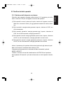
5.3.7 Impostazione del numero di indirizzo - Interfaccia RS485 con dispositivo esterno
Schermo e pulsanti
V I SUA L I ZZ A
* [ kWh ] / [ kW ]
1
I ND I R I Z ZO I NV .
( 01 )
Procedura
Premere gli interruttori POWER ed
ENTER per due secondi o più a lungo.
Sul pannello LCD compare l'indicazione "VISUALIZZA".
Premere due volte l'interruttore
ENTER. Sul pannello LCD compare
l'indicazione "INDIRIZZO INV".
2
Lampeggiante
I ND I R I Z ZO I NV .
( 01 )
1. Ogni pressione del pulsante
SELECT cambia il valore lampeggiante:
→ 1 → 2 → …9 → 0
Lampeggiante
I ND I R I Z ZO I NV .
( 01 )
3
Lampeggiante
2. Se si preme l'interruttore MODE,
inizia a lampeggiare un'altra cifra.
Ripetere la procedura per impostare il valore desiderato, nell'intervallo da 1 a 30.
L'interruttore RS485 nell'invertitore PV situato più indietro è impostato su ON e gli
altri invertitori PV sono impostati su OFF.
Jack modulare per
interfaccia RS485
Morsetto DC RS485
ON
OFF
Interruttore RS485
38
PV-IB-Italian 08.3.6 10:02 ページ39
Schermo e pulsanti
4
5
Se si desidera terminare l'impostazione
dell'indirizzo, premere l'interruttore
POWER per due o più secondi.
Sul pannello LCD viene visualizzata
l'indicazione "----".
39
Italiano
I ND I R I Z ZO I NV .
( 01 )
Procedura
Premere l'interruttore ENTER per registrare il numero di indirizzo.
(L’inverter PV torna alla fase 1 precedente).
PV-IB-Italian 08.3.6 10:02 ページ40
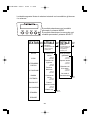
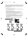
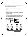
5.3.8 Procedura di impostazione per interfaccia RS485 con invertitori multipli
Se, tramite l'interfaccia RS485, si esegue la comunicazione con più di due
invertitori, è necessario impostare il numero di indirizzo degli invertitori e
dell'interruttore RS485.
(1) Impostazione del numero di indirizzo
5.3.7 Impostazione del numero di indirizzo - Interfaccia RS485 con dispositivo esterno.(Vedere p.38)
(2)Impostazione dell'interruttore RS485
L'interruttore RS485 è situato sul lato sinistro del terminale in c.c.
L'interruttore RS485 è del tipo a tre posizioni. Quando l'interruttore è
impostato verso l'alto, la resistenza terminale è connessa.
Quando l'interruttore si trova nella posizione mediana o in quella inferiore, la resistenza terminale non è connessa.
Con l'invertitore che connette la maggioranza dell'estremita della linea di
comunicazione, l'interruttore RS485 va impostato in posizione "ON".
L'interruttore RS485 dell'altro invertitore deve essere impostato in
posizione "OFF".
(Impostazione predefinita: interruttore RS485 in posizione "ON").
Jack modulare per interfaccia RS485
(uno serve per la comunicazione e l'altro
per la linea a ricadute multiple)
Interruttore RS485
(3 posizioni)
ON
OFF
OFF
Indirizzo = 9
Interruttore
RS485=
ON
Indirizzo = 8
Interruttore
RS485=
Indirizzo = 2
Interruttore
RS485=
OFF
OFF
Dispositivo di comunicazione
40
Indirizzo = 1
Interruttore
RS485=
OFF
PV-IB-Italian 08.3.6 10:02 ページ41
6 Maintenance
6.1 Operazioni di manutenzione giornaliera
Disattivare sempre gli interruttori AC e DC prima di eseguire operazioni di
manutenzione ordinaria. (In caso contrario l’utente può subire scosse elettriche).
ATTENZIONE
Non usare olio, detergenti o altri agenti simili elencati qui sotto
per pulire l’inverter PV.
Diluente, alcol, benzene, gas, olio di carbone, spray, detersivi, ecc.
In caso contrario si possono verificare perdite di colore o deterioramento.
Non pulire l’inverter PV con un panno umido.
L’utente può subire una scarica elettrica.
Indossare i guanti di protezione quando si pulisce l’inverter PV.
Spigoli vivi come quelli delle aperture di ventilazione possono provocare lesioni.
Non toccare le aperture di ventilazione dell’inverter PV o le zone circostanti
durante il funzionamento o nei momenti immediatamente successivi allo
spegnimento. La temperatura delle superfici in questione può superare i 60°C.
L’utente può subire un’ustione.
Eseguire le seguenti operazioni di manutenzione giornaliera dell’inverter PV.
Prima di utilizzare il dispositivo
1. Tenere premuto il pulsante POWER per due secondi o più per
disattivare l’inverter PV (vedere p.14).
2. Disattivare l’interruttore DC
3. Disattivare l’interruttore AC
●Aspirare con regolarità la polvere dall’apertura di ventilazione, almenoogni tre mesi. Eventuali aperture ostruite riducono la ventilazione attraverso
l’inverter PV, con effetti negativi sulla potenza di uscita.
●Pulire eventuali contaminazioni dello schermo con un panno asciutto, o
con un mezzo simile.
●Verificare con regolarità, almeno annualmente eventuali guasti o sganciamenti. Verificare anche se la posizione dell’inverter PV continua a
essere corretta (a piombo).
41
Italiano
AVVERTENZA
PV-IB-Italian 08.3.6 10:02 ページ42
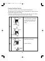
Pulizia dell’apertura di ventilazione
Disattivare l’inverter PV. Disattivare gli interruttori AC e DC.
Subito dopo la disattivazione l’apertura è molto calda. Attendere per alcuni
minuti prima di pulire l’apertura di ventilazione.
※Pulire l’apertura di ventilazione SOLO sul lato destro dell’inverter PV. NON
toccare l’apertura sul lato sinistro dell’inverter PV.
Rimozione
Griglia
1
Spingere in alto la griglia di protezione. Sganciare ed estrarre la
griglia agendo sull’estremità inferiore. Questo consente di rimuovere la griglia.
Spingere
verso l'alto
Griglia
Sganciare
Pulizia
1. Far scorrere ed estrarre il filtro.
Manopola
Filtro
2. Pulire il filtro con l’aspirapolvere.
2
Aspirapolvere
Filtro
42
PV-IB-Italian 08.3.6 10:02 ページ43
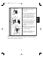
Montaggio
Filtro
Fessura
Linguetta
2. Inserire la linguetta della griglia
nella fessura della sezione superiore dell’apertura di ventilazione
dell’inverter PV. La linguetta
dovrebbe scorrere verso l’alto
nella fessura.
3. Con la linguetta della griglia ben
inserita nella fessura, spingere in
alto e quindi tirare leggermente
verso il basso la griglia mentre la
si spinge con delicatezza verso
l’apertura.
3
Supporto A
Apertura di ventilazione
Griglia
● Questo movimento permette di
Inserire
agganciare il supporto A della
griglia nel supporto A dell’apertura di ventilazione.
4. Accertarsi che la griglia sia ben
fissata.
Fissare
Una volta terminato di eseguire le operazioni di manutenzione giornaliera,
attivare gli interruttori AC e DC. Premere e tenere premuto il pulsante
POWER per due secondi o più per assicurarsi che l’inverter PV si avvii.
43
Italiano
1. Far scorrere il filtro sino a fargli
toccare il fondo. Questo significa
che il filtro è in posizione corretta.
PV-IB-Italian 08.3.6 10:02 ページ44
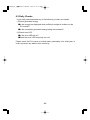
6.2 Verifiche quotidiane
Se la verifica quotidiana rileva quanto segue, contattare il rivenditore.
(1)Verifica dell’energia generata
●Se la luce solare che illumina il modulo PV è sufficiente, sullo schermo
LCD compare la barra dell’energia?
●Il valore cumulativo dell’energia generata cresce?
(2)Verifica del LED ERROR
● Il LED ERROR rimane acceso?
● Il LED ERROR si accende frequentemente?
Verificare l’inverter PV su base quotidiana, particolarmente nel suo primo
anno, per prevenire l’insorgenza di eventuali difetti.
44
PV-IB-Italian 08.3.6 10:02 ページ45
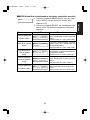
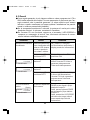
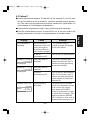
6.3 Guasti
●Come regola generale, si può ritenere valido un valore compreso tra il 70 e
Schermo
Causa
Rimedio
Nessuna informazione Nessuna informazione Se i moduli PV ricevono
viene visualizzata sullo un’illuminazione sufficiente, il
visualizzata.
schermo LCD durante display mostra le informazioni.
la notte o quando la
luce solare è minima.
L’interruttore DC è in Portare l’interruttore DC in
posizione OFF?
posizione ON.
STANDBY 2 0 s e c
1 2 3 4 5 kWh
Si è verificato un
blackout?
è visualizzato.
BLACKOUT
1 2 3 4 5 kWh
è visualizzato.
Il LED ERROR è
attivo.
(Tipico)
ERRORE
E - 09
1 2 3 4 5 kWh
è visualizzato.
Dopo un intervallo dai 2 ai 5
minuti l’inverter PV inizia a
generare potenza senza
l’intervento dell’operatore.
Si è verificato un
blackout?
L’interruttore AC è in Trascorsi dai 2 ai 5 minuti dopo
posizione OFF?
il ritorno dell’alimentazione,
l’inverter PV inizia a generare
potenza senza l’intervento
dell’operatore.
Si attiva il dispositivo Premere e tenere premuto il pulsante
POWER per due secondi o più per
di sicurezza.
disattivare l’inverter PV.
Quindi, premere il pulsante POWER
per due secondi o più per riattivare
l’inverter PV.
Quindi, accertarsi che il LED ERROR
sia inattivo e che nessun codice di
errore compaia dopo l’inizio del
funzionamento.
45
Italiano
l’80% della capacità del modulo PV come parametro di riferimento per l’energia massima che è possibile generare. (Il valore effettivo può essere
inferiore a quello menzionato qui sopra qualora l’installazione sia parzialmente in ombra o presenti altri problemi).
● Se la temperatura ambiente è elevata, la potenza di uscita può subire
drastiche riduzioni. In tal caso, contattare il rivenditore.
● Se l’inverter PV non funziona, oppure se si accende il LED ERROR o
compare un messaggio di errore, fare riferimento all’elenco di contromisure indicato nella tabella seguente.
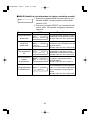
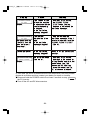
PV-IB-Italian 08.3.6 10:02 ページ46
Schermo
PREGO PUL I RE
I L F I L TR O !
lampeggia.
PREGO PUL I RE
I L F I L TR O !
continua a
lampeggiare. Il
pulsante ENTER
non si disattiva al
prompt.
Bassa potenza di
uscita
NESSUNA DATA / ORA
I MPOSTARE !
lampeggia.
Causa
Rimedio
Questo messaggio
lampeggia a intervalli
regolari per richiedere
la verifica delle aperture
di ventilazione.
LÕapertura di
ventilazione bloccata?
Premere il pulsante ENTER.
Il messaggio "PREGO
PULIRE IL FILTRO!" smette
di lampeggiare.
Quindi, vedere p. 44 per
pulire le aperture di
ventilazione.
La temperatura
interna troppo
elevata.
LÕapertura di
ventilazione
bloccata?
Vedere p. 44 per pulire le
aperture di ventilazione.
Quando il sistema ritorna alla
normalit il messaggio
"PREGO PULIRE IL FILTRO!"
si disattiva.
LÕapertura di
Vedere p. 44 per pulire le
ventilazione bloccata? aperture di ventilazione.
Non viene impostata Premere il pulsante ENTER.
alcuna data e ora.
Questo fa comparire lo
schermo per lÕimpostazione
di data e ora. Impostare data
e ora. La sottosezione "5.3.3
Impostazione data e ora" (p.
27) serve da riferimento.
Se, anche dopo aver eseguito le azioni suggerite, l’errore persiste, procedere come segue e quindi contattare il rivenditore per operazioni di
riparazione o checkup.
●Premere e tenere premuto il pulsante POWER per 2 secondi
o più per disattivare l’inverter PV.
●Disattivare gli interruttori AC e DC.
46
PV-IB-Italian 08.3.6 10:02 ページ47
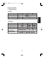
7 Dati tecnici
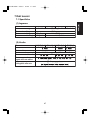
7.1 Specifiche
PV-PNS03ATL-IT PV-PNS04ATL2-IT PV-PNS04ATL-IT PV-PNS06ATL-IT
Elemento
700 V c.c.
Max. tensione ingresso
150 V c.c.
Min. tensione di ingresso
18,0 A c.c.
Max. corrente di ingresso 12,0 A c.c.
2
3
Numero max. di stringhe
(2) Uscita
Elemento
PV-PNS03ATL-IT PV-PNS04ATL2-IT PV-PNS04ATL-IT PV-PNS06ATL-IT
Uscita nominale
2,5 kW
3,3 kW
4,6 kW
Max. uscita
3,0 kW
3,5 kW
5,0 kW
230 V c.a.
Tensione uscita nominale
Max. corrente di uscita
13,0 A c.a.
15,2 A c.a. 21,7 A c.a.
Gamma operativa, col A valori stabilizzati, OVR, UVR, OFR e UFR
legato alla rete attiva
Collegabile alla rete
230 V c.a. monofase
(collegabile con sistema monofase)
47
Italiano
(1) Ingresso
PV-IB-Italian 08.3.6 10:02 ページ48
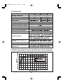
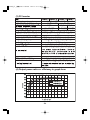
(3) Inverter PV
Elemento
Requisiti ambientali
Max. efficienza di conversione
Efficienza di conversione EUROPEA
Gamma MPPT
Fattore di potenza dell’onda di uscita
Fattore di distorsione della corrente armonica
Consumo energetico notturno
Rumore
Sistema di conversione
Sistema di commutazione
Tipo di messa a terra
Controllo potenza
Controllo della corrente di
ingresso
Avvio e stop automatici
Controllo della ventola di raffreddamento
! "#$! "%&' & (#)!*+! %! (*" *,*)*
#!- %*"%#* *&&.#"%* !+*&
/0 + / (! %**"%1 "+* / %!!&&! /& $! / "!
"+* 2 * !/* "#"!/*&
"+* "!&*! ")* *"(!+*!
7#)!* ! 5& ,*&& $,"- +*4' $!)*
/ #"%* +*4 %! / #"%* +*4 %! /
5""!' #*,* " &* +$*#* * "*&
* 89 *&&!* &.#"%* , &+** *& !
/&&* $!)* +*""+* / #"%*'
3#"* %! , %!!&&** +!/! /* ! %!"
& "#$*+! /& ,*&! +*4' %! / 5""!'
&&* "6#)* / *,,! "!$'
!!&&* &* ,!&* / *((//*+! :*"**"#&&* +$*#*
* &* $!)* / #"%* 5!&*/! & (&#""! /&&.**'
(4) Tasso di potenza di uscita ed efficienza in forma di grafico
!"
!"
!"
!"
#$%&"'
#$%&"'
#$%&"'
#$%&"'
48
PV-IB-Italian 08.3.6 10:02 ページ49
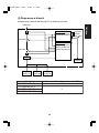
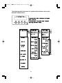
(5) Diagramma a blocchi
Il diagramma a blocchi dell’inverter PV è illustrato qui sotto.
Dalla rete
monitoraggio della frequenza,
rilevamento del guasto di terra
Interruttore
POWER
Stop
Run
Relè principale
Controller 1
Tensione della rete, monitoraggio della frequenza,
rilevamento dell’effluenza DC,
rilevamento del guasto di terra
Relè rete
DC/AC
Schermo
Stringa
modulo PV
Stringa
modulo PV
Modello
PV-PNS03ATL-IT
PV-PNS04ATL2-IT
PV-PNS04ATL-IT
PV-PNS06ATL-IT
Stringa
modulo PV
Numero della stringa del modulo PV
2
3
49
Italiano
Inverter PV
Controller 2
PV-IB-Italian 08.3.6 10:02 ページ50
7.2 Impostazioni
L’inverter PV presenta una modalità per la visualizzazione del nome del
paese e per la soluzione di possibili problemi di rete.
Visualizzazione dell’impostazione della funzione di protezione
della rete
Schermo e pulsanti
Procedura
Premere simultaneamente gli interruttori
POWER e MODE per 2 secondi o più.
I MPOS T A TO
I TA L I A
1
・Il nome del paese, una specifica per
la soluzione di possibili problemi di
rete, è visualizzato sullo schermo
LCD.
Se il nome del paese nel quale si è
installato l’inverter PV e il luogo visualizzato nello schermo LCD non coincidono, consultare il rivenditore.
2
Quindi, premere il pulsante POWER
per due secondi o più per annullare la
modalità di visualizzazione dell’impostazione.
50
PV-IB-Italian 08.3.6 10:02 ページ51
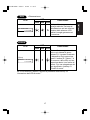
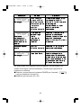
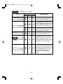
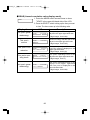
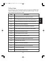
7.3 Codici di errore
Codice
Descrizione
E-00
L’interruttore interno funziona in modo anomalo.
E-05
Le informazioni di configurazione incl. le impostazioni sono
state recuperate in modo inappropriato all’avvio del sistema.
E-07
Impossibile rilevare le informazioni sulla temperatura interna.
E-08
Il circuito di controllo funziona in modo improprio.
E-09
È stata rilevata una temperatura interna eccessiva.
E-20
La tensione di ingresso ha superato il valore massimo di
tensione di ingresso ammesso.
E-24
Si è verificata una sovracorrente in uscita.
E-25
Si è verificata una sovratensione in uscita.
E-26
Si è verificata una caduta di tensione in uscita.
E-28
La corrente diretta è in sovrapposizione con la corrente di
uscita.
E-29
Si è verificato un guasto di terra.
E-30
Il circuito di amplificazione funziona in modo improprio.
E-31
Il circuito di rilevazione dei guasti di terra funziona in modo
improprio.
E-35
Il fusibile termico è saltato.
E-37
Si è verificato un errore nel circuito booster.
51
Italiano
Nell’eventualità di un guasto all’inverter PV o alla rete che porti all’accensione del LED ERROR e alla visualizzazione di un codice di errore, contattare il rivenditore per la riparazione. Questa sottosezione descrive i codici
di errore più comuni.
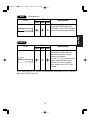
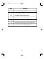
PV-IB-Italian 08.3.6 10:02 ページ52
Codice
Descrizione
E-43
Si è verificato un errore nel circuito booster.
E-44
Le impostazioni predefinite sono errate.
E-62
Sovratensione nel circuito booster.
E-64
Sovracorrente nel circuito inverter.
E-66
Si è verificata una sovratensione in ingresso
(livello elevato).
E-72
Si è verificata una sovratensione nel circuito di amplificazione (livello elevato).
E-73
Si è verificata una sovracorrente nell’elemento di commutazione.
52
PV-IB-Italian 08.3.6 10:02 ページ53
8 Glossario
AC
Acronimo di corrente alternata.
Un dispositivo elettronico che fornisce energia quando viene irradiato. Un
gruppo di celle collegate l’una all’altra compone un modulo PV.
Corrente di uscita
Corrente elettrica di uscita dall’inverter PV.
DC
Acronimo di corrente continua.
Effluenza DC
Componente DC incluso nella potenza di uscita rilevata sull’inverter PV.
Energia
Indica l’energia elettrica cumulativa generata dal modulo PV.
Energia acquistata
L’energia elettrica acquistata dalla società produttrice necessaria per ripanare i consumi degli elettrodomestici.
Energia venduta
Energia generata nel sistema PV e venduta alla società elettrica.
Energia cumulativa totale
Energia totale generata nel sistema PV, accumulata dal momento in cui
l’inverter PV è stato installato sino al presente.
Energia solare
L’energia fornita dal sole in forma di radiazioni quali la luce solare che
include calore e onde ultraviolette.
Guasto di terra
Segnala la rilevazione di una corrente di guasto di terra sull’inverter PV.
Importo
Si riferisce all’importo di energia elettrica venduta alla società produttrice.
LCD
Acronimo di schermo a cristalli liquidi. I vari stati operativi dell’inverter PV
sono visualizzati sullo schermo LCD integrato.
Potenza di uscita
Potenza elettrica di uscita dell’inverter PV.
PV
Un termine impiegato per indicare la conversione di energia solare in
energia elettrica.
Riduzione di CO2
Quando appare sullo schermo LCD, indica la riduzione di CO2 (generata
altrimenti) ottenuta dal sistema PV.
Stringa
Un gruppo di moduli PV collegato in serie.
Tensione di ingresso
Tensione di ingresso dell’inverter PV.
53
Italiano
Cella solare
PV-IB-Italian 08.3.6 10:02 ページ54
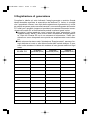
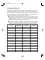
9 Registrazione di generazione
Compilare la tabella qui sotto indicando l’energia generata e venduta. Questa
tabella dovrebbe agevolare la supervisione del sistema PV. Inoltre, si consiglia
che il proprietario conservi una copia della registrazione di generazione in modo
da poterla recuperare anche successivamente a un eventuale guasto dell’inverter
PV. Infatti non è possibile (neppure al produttore) recuperare informazioni memorizzate nell’inverter PV ed eventualmente perdute a causa di guasti o altro.
●Annotate il valore mostrato come energia del mese precedente (nella
modalità display “MESE”) nelle colonne sotto l’intestazione “Energia generata”. Dato che l’inverter PV non è uno strumento di misurazione, i valori visualizzati non vanno interpretati come precisi ma semplicemente come indicativi.
●Nelle colonne che stanno sotto l’intestazione “Energia ceduta”, annotare l’energia indicata sul conto o sulla fattura fornita dalla società elettrica. Si possono inoltre annotare le letture del contatore di una giornata definita di ogni
mese.
AA MM GG
Energia
generata (kWh)
Energia
venduta (kWh)
54
Energia
acquistata (kWh)
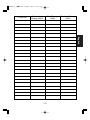
PV-IB-Italian 08.3.6 10:02 ページ55
AA MM GG
Energia
generata (kWh)
Energia
venduta (kWh)
Energia
acquistata (kWh)
Italiano
55
PV-IB-Italian 08.3.6 10:02 ページ56
PV-IB_IT_英表示-3.3 08.3.6 10:14 ページ57
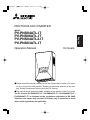
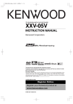
PHOTOVOLTAIC INVERTER
MODEL
English
PV-PNS04ATL-IT
PV-PNS06ATL-IT
PV-PNS04ATL2-IT
PV-PNS03ATL-IT
Operation Manual
for Users
●Please read this manual carefully to use the Photovoltaic inverter (PV inverter) in a correct and safe manner. Please pay particular attention to the section "Safety Precautions" before using the PV inverter.
●The manual should always be readily available to the operator of the PV inverter.
The PV inverter PV-PNS04ATL-IT / PV-PNS06ATL-IT / PV-PNS04ATL2-IT /
PV-PNS03ATL-IT is designed to the regulations stipulated in DK 5940.
Therefore, the owner may use the PV inverter only in countries or areas
where such regulations are applicable.
57
PV-IB_IT_英表示-3.3 08.3.6 10:14 ページ58
Table of Contents
Page
Introduction •
• • • • • • • • • • • • • • • • • • • • • • • • • • • • • • • • • • • • • • • • • • • • • •
60
1 Safety Precautions • • • • • • • • • • • • • • • • • • • • • • • • • • • • • • • • • • • • 61∼63
2 Applicable Standards • • • • • • • • • • • • • • • • • • • • • • • • • • • • • • • • • • • • • • 64
3 Configuration of PV System
• • • • • • • • • • • • • • • • • • • • • • • • • • • • •
65∼66
4 Parts and Their Names • • • • • • • • • • • • • • • • • • • • • • • • • • • • • • • • • 67∼68
4.1 Appearance • • • • • • • • • • • • • • • • • • • • • • • • • • • • • • • • • • • • • • • • • 67
4.2 Display Panel •
4.3 Cable Glands •
5 Operation •
• • • • • • • • • • • • • • • • • • • • • • • • • • • • • • • • • • • • • • •
• • • • • • • • • • • • • • • • • • • • • • • • • • • • • • • • • • • • • • •
• • • • • • • • • • • • • • • • • • • • • • • • • • • • • • • • • • • • • • • • • •
67
68
69∼96
5.1 Operating Procedure • • • • • • • • • • • • • • • • • • • • • • • • • • • • • • • 69∼70
5.1.1 Start (Turn on) • • • • • • • • • • • • • • • • • • • • • • • • • • • • • • • • • • • 69
5.1.2 Stop (Turn off)
• • • • • • • • • • • • • • • • • • • • • • • • • • • • • • • • • • •
5.2 Viewing Operating Status
• • • • • • • • • • • • • • • • • • • • • • • • • • •
70
71∼74
5.2.1 Viewing LCD and LEDs • • • • • • • • • • • • • • • • • • • • • • • • • 71∼73
5.2.2 Actions When Error LED Turns On • • • • • • • • • • • • • • • • • • • • 74
5.3 Viewing Operation Data •
• • • • • • • • • • • • • • • • • • • • • • • • • • • •
5.3.1 Selecting Display Item
• • • • • • • • • • • • • • • • • • • • • • • • •
75∼96
75∼77
5.3.2 Description of Display Items • • • • • • • • • • • • • • • • • • • • • • 78∼82
5.3.3 Setting Current Date and Time (24 Hour Clock) • • • • • • • • • • • 83
5.3.4 Setting Display Language • • • • • • • • • • • • • • • • • • • • • • • • • • • 84
5.3.5 Setting Unit Price for Selling Energy • • • • • • • • • • • • • • • • • • • 85
5.3.6 Operating in AUTO TEST Mode • • • • • • • • • • •
5.3.7 Setting Address Number - RS485 interface with
• • • • • • •
86∼93
external device • • • • • • • • • • • • • • • • • • • • • • • • • • • • • • • 94∼95
5.3.8 Procedure of setup for RS485 interface with multiple inverters • • • • • 96
6 Maintenance •
• • • • • • • • • • • • • • • • • • • • • • • • • • • • • • • • • • • • • • •
97∼102
6.1 Daily Care• • • • • • • • • • • • • • • • • • • • • • • • • • • • • • • • • • • • • • • 97∼99
6.2 Daily Checks • • • • • • • • • • • • • • • • • • • • • • • • • • • • • • • • • • • • • • • 100
6.3 Failure!? •
• • • • • • • • • • • • • • • • • • • • • • • • • • • • • • • • • • • • •
58
101∼102
PV-IB_IT_英表示-3.3 08.3.6 10:14 ページ59
7 Technical Data
• • • • • • • • • • • • • • • • • • • • • • • • • • • • • • • • • • • • •
103∼108
7.1 Specifications • • • • • • • • • • • • • • • • • • • • • • • • • • • • • • • • • • 103∼105
7.2 Settings • • • • • • • • • • • • • • • • • • • • • • • • • • • • • • • • • • • • • • • • • • • 106
7.3 Error Codes • • • • • • • • • • • • • • • • • • • • • • • • • • • • • • • • • • • 107∼108
8 Glossary • • • • • • • • • • • • • • • • • • • • • • • • • • • • • • • • • • • • • • • • • • • • • • 109
9 Generation Record
• • • • • • • • • • • • • • • • • • • • • • • • • • • • • • • • • •
110∼111
English
59
PV-IB_IT_英表示-3.3 08.3.6 10:14 ページ60
Introduction
Thank you for selecting the PV inverter PVPNS04ATL-IT / PV-PNS06ATL-IT / PV-PNS04ATL2IT / PV-PNS03ATL-IT. This manual illustrates the
operation of the PV inverter PV-PNS04ATL-IT / PVPNS06ATL-IT / PV-PNS04ATL2-IT / PV-PNS03ATLIT. Please use this manual as a guide to enjoy the
wealth of features offered by the PV inverter.
Installation of the PV inverter PV-PNS04ATL-IT / PV-PNS06ATL-IT / PVPNS04ATL2-IT / PV-PNS03ATL-IT is illustrated in the separate "PHOTOVOLTAIC INVERTER PV-PNS04ATL-IT / PV-PNS06ATL-IT / PVPNS04ATL2-IT / PV-PNS03ATL-IT Installation Manual".
60
PV-IB_IT_英表示-3.3 08.3.6 10:14 ページ61
1 Safety Precautions
●The following symbols denote the type and degree of danger that may result from incorrect use.
WARNING
Important
Alerts you of the danger of death or
serious injury anticipated if the PV inverter
is worked on in the wrong manner.
Before working on the PV inverter, always press the Power
switch on the PV inverter to stop running. Turn off both the AC
and DC disconnectors.
Do not leave faulty PV inverter unseen to.
If any fume or abnormal odor is detected, first turn the equipment off
with its power switch. Second, turn off both the AC and DC
disconnectors. Then, contact your dealer.
Do not use the PV inverter in purposes other than PV
generation.
Fire, electric shock, or injury may result.
Prohibited Do not inspect the PV inverter yourself.
Electric shock may result.
Do not place or feed any metal or water into the ventilation
opening of the PV inverter.
Electric shock may result.
Do not climb or hang on the PV inverter.
It may fall, resulting in injury.
Do not disassemble or modify the PV inverter.
Fire, electric shock, or injury may result.
Don’t disassemble
or modify
Do not touch the PV inverter during a thunderstorm or a natural disaster.
Electric shock may result.
Don’t touch Do not open the front panel of the PV inverter.
Touching the inside of the PV inverter could cause an electric shock.
61
English
Electric shock may result.
PV-IB_IT_英表示-3.3 08.3.6 10:14 ページ62
CAUTION
Warns you of potential injury or damages
anticipated to the building or household stuff if the
PV inverter is worked on in the wrong manner.
Do not place any thing on the PV inverter.
Do not obstruct the ventilation opening of the PV inverter.
Fire, electric shock, or injury may result.
Do not expose the PV inverter to cold air or steam.
Any accumulated frost could cause faulty current or burnout.
Prohibited
Do not run the PV inverter in the vicinity of high-frequency
equipment such as walkie-talkies.
A glitch could cause burnout.
Do not wipe the PV inverter with a wet cloth.
Electric shock may result.
Wear gloves when wiping the PV inverter.
Edges such as the ventilation openings may cause injury.
Important
Do not touch the PV inverter’s ventilation opening or its
surroundings when running, or immediately after stopped
running. It can be higher than 60℃.
Don’t touch Burn may occur.
62
PV-IB_IT_英表示-3.3 08.3.6 10:14 ページ63
CAUTION
Do not install the PV inverter in the following places:
(Otherwise, the PV inverter may fail or its safe use may be impeded.
The product warranty shall also be voided.)
・Outdoors, or places similar to outdoors (※It is PROHIBITED to install the
PV inverter in places unable to be separated from outdoor environment,
such as garage open at one side, no wall or door able to block such side,
・Places where it is exposed to direct sunlight
・Narrow places lacking ventilation
・Places where it is exposed to water
・Places where humidity is significantly high such as lavatory or bathroom
・Places where excessive steam, oil vapor, smoke, dust, or corrosive substance is present
・Places where it is exposed to oily smoke, such as a kitchen
・Places where explosive or flammable gases are present
・Places installations are exposed to vibration or shock
・Places in the vicinity of flammable materials
・Places with unusual conditions other than those indicated above (such as
seafaring vessels or motor vehicles)
・Places where damage from salt air could occur
Note
Avoid installing the PV inverter in the following places:
(Otherwise, the PV inverter might cause appliances to generate noises.)
・Places where noises or electric noises are under strict control
・Places in the vicinity of television or radio antennas or cables
63
English
provided.)
PV-IB_IT_英表示-3.3 08.3.6 10:14 ページ64
2 Applicable Standards
Your PV inverter complies with the rules and regulations stipulated by LVD,
EMC, and CE. It also complies with the regulations defined in EN, CEI 11-20
and DK 5940. The PV inverter also meets the provisions defined regarding
electromagnetic compatibility (EMC) and low voltage directive (LVD) as certified in the CE declaration.
Information on Disposal
Note: This symbol mark is for EU countries only.
This symbol mark is according to the directive 2002/96/EC
Article 10 Information for users and Annex IV.
Your MITSUBISHI ELECTRIC product is designed and manufactured
with high quality materials and components which can be recycled
and reused.
This symbol means that electrical and electronic equipment, at their endof-life, should be disposed of separately from your household waste.
Please, dispose of this equipment at your local community waste
collection/recycling centre.
In the European Union there are separate collection systems for used
electrical and electronic product.
Please, help us to conserve the environment we live in !
64
PV-IB_IT_英表示-3.3 08.3.6 10:14 ページ65
3 Configuration of PV System
Overview of Basic System
②
③
④
①
②
③
④
The PV inverter converts direct-current energy generated by Photovoltaic
modules (PV modules) into alternating-current energy, and provides it for
use with the grid.
① Photovoltaic module (PV module)
This converts solar light energy into direct-current energy.
A group of solar cells makes up a PV module.
A group of PV modules is called a PV module
array.
65
English
①
PV-IB_IT_英表示-3.3 08.3.6 10:14 ページ66
② DC disconnector
This is inserted between the PV module and the
PV inverter, makes or breaks the circuit on the
PV module side.
③ PV inverter
This converts direct-current energy generated by
the PV module into alternating-current energy.
④ AC disconnector
This is inserted between the grid and the PV
inverter, makes or breaks the circuit on the grid
side.
66
PV-IB_IT_英表示-3.3 08.3.6 10:14 ページ67
4 Parts and Their Names
4.1 Appearance
Front panel
①
①
② Display panel
English
②
① Ventilation openings
③ Cable glands
③
4.2 Display Panel
The display panel includes one LCD, three LEDs, and four switches. They
allow you to view a variety of operation data, and to perform necessary operations on the PV inverter.
⑧
⑦
⑥
①
②
③
④
⑤
① POWER LED
⑤ ENTER switch
② POWER switch
⑥ GRID LED
③ MODE switch
⑦ ERROR LED
④ SELECT switch
⑧ LCD
67
PV-IB_IT_英表示-3.3 08.3.6 10:14 ページ68
4.3 Cable Glands
The PV inverter has the following cable glands.
④
①
②
③
① ② ③ ④
68
PV-IB_IT_英表示-3.3 08.3.6 10:14 ページ69
5 Operation
The following illustrates the operation of the PV inverter.
5.1 Operating Procedure
The operating procedure to start or stop the PV inverter is illustrated below.
5.1.1 Start (Turn on)
Display panel
Procedure
1
・The PV inverter starts up, with the
"gate" displayed on the LCD starting
to open.
The LCD displays "START" for 3 seconds, and then switches to the display
in STATUS mode.
START
2
PLEASE WA I T . . .
1 2 3 4 5 kWh
(For: Preparing itself for running)
3
RUNN I NG
1 2 3 4 5 kWh
Afterwards the LCD displays information such as messages, state of power
generation, total generated energy,
etc., available in its modes of operation.
(For: Running with the grid connected) For details, refer to "5.2 Viewing
Operating Status".
After turning on inverter, the PV inverter automatically runs depending on
amount of sunlight.
69
English
When the PV inverter is inactive, press
and hold the POWER switch for 2 seconds or longer.
PV-IB_IT_英表示-3.3 08.3.6 10:14 ページ70
5.1.2 Stop (Turn off)
To stop the PV inverter, use the following procedure.
Display panel
RUNN I NG
1 2 3 4 5 kWh
Procedure
When the PV inverter is running, press
the POWER switch for 2 seconds or
longer.
1
STOP
・This stops the PV inverter and
"STOP" is displayed for 3 seconds.
The "gate" starts closing on the LCD.
2
The PV inverter stops.
3
・"----" on the LCD indicates the PV
inverter is inactive.
70
PV-IB_IT_英表示-3.3 08.3.6 10:14 ページ71
5.2 Viewing Operating Status
The PV inverter displays on its LCD and LEDs the status as dictated
by its operating condition in that instance. All of the LCD and LEDs
are off during the night or at a time when little sunlight is present. This
is caused by the power source turned off on the PV inverter.
5.2.1 Viewing LCD and LEDs
Each operating status displayed on the LCD and LEDs is listed below.
denotes on,
denotes flashing, and
denotes off.
※ A numerical value is shown on the lower right-hand side of the LCD
representing the generated energy in kWh.
STOP
(Turn off)
LCD
LED
POWER GRID ERROR
Description
The LCD and all LEDs are off
during times in which (1) little
sunlight is present such as at
night, or (2) the DC disconnector is off. This is caused by the
power source turned off on the
PV inverter.
(Display is off)
The PV inverter has "stopped"
running.
Operating the POWER switch
will turn on the PV inverter.
71
English
※ LED:
PV-IB_IT_英表示-3.3 08.3.6 10:14 ページ72
<Waiting> (Turn on)
RUN
LCD
LED
POWER GRID ERROR
The PV inverter is in the preparation stage for generating power.
The PV inverter then starts running.
PLEASE WA I T . . .
1 2 3 4 5 kWh
The irradiation level has temporarily dropped. The PV inverter is on standby until the irradiation returns to a certain level.
LOW I NPUT POWER
1 2 3 4 5 kWh
Since it is low on irradiation, the PV
inverter avoids running in a mode in
which the grid is connected.
A blackout is encountered, or
the AC disconnector is off.
BLACKOUT
1 2 3 4 5 kWh
The grid-protection function is
active. The PV inverter is on
standby, waiting until the grid is
restored to its normal level.
STANDBY
1 2 3 4 5 kWh
Flashing
STANDBY
Description
The grid-protection function is
active. The numerical value on
the upper right-hand side of the
LCD denotes the time in seconds until the PV inverter
resumes the generation of
power.
20sec
1 2 3 4 5 kWh
72
PV-IB_IT_英表示-3.3 08.3.6 10:14 ページ73
<Generating>
RUN
LCD
LED
POWER GRID ERROR
Description
Power is being generated. The
power bar on the lower lefthand side of the LCD illustrates
current power being generated.
RUNN I NG
1 2 3 4 5 kWh
English
ERROR
LCD
LED
POWER GRID ERROR
A failure in the grid or in the PV
generation system that has
activated the built-in safety
device is indicated.
The [E-**](** for number) on the
upper right-hand side corresponds to an error code.For
error codes, see p.107 "Error
Codes."
(Typical)
ERROR
Description
E - 24
1 2 3 4 5 kWh
If the Error LED is on, follow the procedure described in p.74 "Actions
When Error LED Turns On."
73
PV-IB_IT_英表示-3.3 08.3.6 10:14 ページ74
5.2.2 Actions When Error LED Turns On
The following action should be taken if the ERROR LED is illuminated.
Display panel
Procedure
1. Press the POWER switch for 2
seconds or longer to turn off the
PV inverter.
2. Make sure that "----" is displayed,
and then press the POWER switch
again for 2 seconds or longer to
restart the PV inverter.
If the procedures illustrated above do not remedy the error (i.e., the
ERROR LED turns on again ), then take the following action.
Display panel
Procedure
1. Press the POWER switch for 2
seconds or longer to turn off the
PV inverter.
2. Turn off the DC disconnector.
3. Turn off the AC disconnector.
4. Contact your dealer for repair or
checkup.
74
PV-IB_IT_英表示-3.3 08.3.6 10:14 ページ75
5.3 Viewing Operation Data
5.3.1 Selecting Display Item
In addition to the operating status illustrated in 5.2, you can monitor a variety of operation data on the LCD.
(1) Current operation data: output power, input voltage, grid voltage, output
current, (today's) maximum output power, date and time
(3) Daily operation data: today's generated energy, amount, CO2 reduction,
operating hours, yesterday's generated energy
(4) Monthly operation data: this month's generated energy, amount, CO2
reduction, operating hours, last month's generated energy
(5) Annual operation data: this year's generated energy, amount, CO2
reduction, operating hours, last year's generated energy
Also, you set information relevant to the items such as date and time while
bringing them up on the LCD.
You can select the items by operating the MODE or SELECT switch.
However, it reverts to STATUS display if 30 seconds and more passe without any actions.
75
English
(2) Total cumulative data: total generated energy, amount, CO2 reduction,
operating hours
PV-IB_IT_英表示-3.3 08.3.6 10:14 ページ76
The following table illustrates the relationships between the modes
and their display items.
$ %
" &'
")*
"!
!#)"
+)
*,---
#+ -!,
!+*
$ %
" &(
!
↓"# !
↓"# !
↓"# !
↓"# !
↓"# !
↓"# !
↓"# !
↓"# .#) /,
")-.
***
76
!
"# !
"# PV-IB_IT_英表示-3.3 08.3.6 10:14 ページ77
Press
MODE
value display
mode)
See p.80
MONTH
(Monthly
Press
MODE
cumulative value
display mode)
See p.81
YEAR
(Annual
cumulative value
display mode)
See p.82
Today's
generated
energy
This month's
generated
energy
This year's
generated
energy
Today's amount
Press
↓SELECT
This month's
amount
This year's amount
Press
↓SELECT
This month's
CO2 reduction
Press
↓SELECT
Yesterday's
generated
energy
Last month's
generated
energy
Press
↓SELECT
Unit price
Press
↓SELECT
Auto test
Press
SELECT
This year's
operating hours
Press
↓SELECT
Press
↓SELECT
Press
SELECT
Language
Press
↓SELECT
This month's
operating hours
Press
↓SELECT
Press
↓SELECT
This year's CO2
reduction
Press
↓SELECT
Today's
operating hours
Date and time
Press
↓SELECT
Press
↓SELECT
SETUP
(Setting
information
display mode)
See pp.83-93
Press
↓SELECT
Press
↓SELECT
Today's CO2
reduction
Press
MODE
Press
SELECT
Last year's
generated
energy
STATUS
77
Press
SELECT
Press
MODE
To "STATUS"
English
DAY
(Daily cumulative
PV-IB_IT_英表示-3.3 08.3.6 10:14 ページ78
5.3.2 Description of Display Items
Operation data viewable in connection with the display items are described below.
(Current value display mode)
●PRESENT(
PRESENT
Display Item
1. Press the MODE switch several times to show
"PRESENT" on the upper left-hand side of the LCD.
2. Press the SELECT switch to bring up the item you want
to view. The item comes up in the following order.
LCD
Description
(Instantaneous value for) Output power is
Output power
PRESENT 2 . 9 kW
OUTPUT POWER
displayed in the upper right-hand side.
(2 digit integer, 1 digit decimal, unit: kW)
Input voltage
PRESENT 4 5 2 . 2Vd c
I NPUT VOL TAGE
Grid voltage
PRESENT 2 3 0 . 2V a c
GR I D VOL TAGE
(Instantaneous value for) Input voltage
present on the PV module is displayed in
the upper right-hand side.
(3 digit integer, 1 digit decimal, unit: Vdc)
(Instantaneous value for) Grid voltage is
displayed in the upper right-hand side.
(3 digit integer, 1 digit decimal, unit: Vac)
Output current
Maximum output
power
Date and time
(24 Hour clock)
PRESENT 1 2 . 8Aa c
OUTPUT CURRENT
(Instantaneous value for) Current
output from the PV inverter is displayed in the upper right-hand side
(3 digit integer, 1 digit decimal, unit: Aac)
PRESENT 3 . 0 kW
MAX OUT PU T TODAY
Maximum output power for today is
displayed in the upper right-hand side.
(2 digit integer, 1 digit decimal, unit:
kW)
15 : 21 : 34
T I ME
2 5 AUG 2 0 0 6
(Current) Hour, minute, and second is
displayed in the upper right-hand side.
(Current) Day, month, and year is
displayed on the lower line.
78
PV-IB_IT_英表示-3.3 08.3.6 10:14 ページ79
(Total cumulative value display mode)
)
●TOTAL(
1. Press the MODE switch several times to show
"TOTAL" in the upper left-hand side of the LCD.
2. Press the SELECT switch to bring up the item you want
to view. The item comes up in the following order.
TOTAL
Display Item
Total generated
energy
Total CO2 reduc-
Description
Total cumulative generated energy is
TOTAL
1 2 3 4 5 kWh
GENERATED ENERGY
displayed in the upper right-hand side.
(5 digit integer, Unit: kWh)
TOTAL
AMOUNT
5 3 6 0 EUR
tion
TOTAL
2 1 8 5 k gC
CO2 REDUCT I ON
Total operating
hours
TOTAL
14002h r
OPERAT I NG HOURS
Total amount of electrical energy
sold to the utility company is displayed in the upper right-hand side.
(5 digit integer, Unit: EUR)
Total quantity of CO2 reduced by the
PV system is displayed in the upper
right-hand side.
(5 digit integer, Unit: kgC)
Total operating hours is displayed in
the upper right-hand side.
(5 digit integer, Unit: hr)
79
English
Total amount
LCD
PV-IB_IT_英表示-3.3 08.3.6 10:14 ページ80
●DAY (Daily cumulative value display mode)
DAY
Display Item
1. Press the MODE switch several times to show
"DAY" in the upper left-hand side of the LCD.
2. Press the SELECT switch to bring up the item you want
to view. The item comes up in the following order.
LCD
Description
Today's generated energy is dis-
Today's generated energy
DAY
2 6 kWh
GENERATED ENERGY
Today's amount
DAY
AMOUNT
played in the upper right-hand side.
(5 digit integer, Unit: kWh)
Amount of energy sold today is dis-
1 1EUR
played in the upper right-hand side.
(5 digit integer, Unit: EUR)
Today's CO2
reduction
DAY
5 k gC
CO2 REDUCT I ON
Today's operating
hours
DAY
10h r
OPERAT I NG HOURS
Yesterday's generated energy
Today's quantity of CO2 reduced by
the PV system is displayed in the
upper right-hand side.
(5 digit integer, Unit: kgC)
Today's operating hours is displayed
in the upper right-hand side.
(5 digit integer, Unit: hr)
Yesterday's generated energy is dis-
DAY
2 3 kWh
YESTERDAY ENERGY
played in the upper right-hand side.
(5 digit integer, Unit: kWh)
80
PV-IB_IT_英表示-3.3 08.3.6 10:14 ページ81
●MONTH (Monthly cumulative value display mode)
MONTH
Display Item
This month's generated energy
This month's CO2
LCD
Description
This month's generated energy is dis-
MONTH
2 9 7 kWh
GENERATED ENERGY
played in the upper right-hand side.
(5 digit integer, Unit: kWh)
Amount of energy sold this month is
MONTH
AMOUNT
1 2 9EUR
displayed in the upper right-hand side.
(5 digit integer, Unit: EUR)
reduction
MONTH
5 3 k gC
CO2 REDUCT I ON
This month's
operating hours
MONTH
300h r
OPERAT I NG HOURS
Last month's generated energy
MONTH
2 8 5 kWh
OCT . 2 0 0 6 ENERGY
This month's quantity of CO 2
reduced by the PV system is displayed in the upper right-hand side.
(5 digit integer, Unit: kgC)
This month's operating hours is displayed in the upper right-hand side.
(5 digit integer, Unit: hr)
Last month's generated energy is displayed in the upper right-hand side.
(5 digit integer, Unit: kWh)
81
English
This month's
amount
1. Press the MODE switch several times to show
"MONTH" in the upper left-hand side of the LCD.
2. Press the SELECT switch to bring up the item you want
to view. The item comes up in the following order.
PV-IB_IT_英表示-3.3 08.3.6 10:14 ページ82
●YEAR (Annual cumulative value display mode)
YEAR
Display Item
This year's generated energy
This year's
amount
This year's CO2
reduction
This year's operating hours
Last year's generated energy
1. Press the MODE switch several times to show
"YEAR" in the upper left-hand side of the LCD.
2. Press the SELECT switch to bring up the item you want
to view. The item comes up in the following order.
LCD
Description
This year's generated energy is dis-
YEAR
3 2 1 8 kWh
GENERATED ENERGY
played in the upper right-hand side.
(5 digit integer, Unit: kWh)
Amount of energy sold this year is dis-
YEAR
AMOUNT
1 3 9 7EUR
played in the upper right-hand side.
(5 digit integer, Unit: EUR)
YEAR
5 7 0 k gC
CO2 REDUCT I ON
This year's quantity of CO2 reduced
by the PV system is displayed in the
upper right-hand side.
(5 digit integer, Unit: kgC)
This year's operating hours is dis-
YEAR
3650h r
OPERAT I NG HOURS
played in the upper right-hand side.
(5 digit integer, Unit: hr)
YEAR
3 3 0 2 kWh
2 0 0 5 ENERGY
82
Last year's generated energy is displayed in the upper right-hand
side.The year is displayed in the
lower left-hand side.
(5 digit integer, Unit: kWh)
PV-IB_IT_英表示-3.3 08.3.6 10:14 ページ83
5.3.3 Setting Current Date and Time (24 Hour Clock)
Display panel
1
SETUP
DA T E / T I ME
Procedure
Press the MODE switch several times
until the "SETUP" mode is displayed.
・"SETUP" is displayed in the upper lefthand side of the LCD. "DATE/TIME" is
displayed on the lower row, telling you
are in the date/time setting mode.
T I ME
15 : 21 : 34
2 5 AUG 2 0 0 6
2
Flashing
T I ME
15 : 21 : 34
2 5 AUG 2 0 1 6
・The PV inverter becomes ready to
accept settings. "Hour, minute, second" and "day, month, and year"
currently registered on the PV
inverter is displayed. The denary
digit starts flashing.
1. Each push of the SELECT switch will
switch the number of the denary digit:
→ 1 → 2 → …9 → 0
Select the number you want to set on the PV inverter.
2. Press the MODE switch.
3
Flashing
・Now the first digit starts flashing (where
you will set the desired number).
T I ME
15 : 21 : 34
2 5 AUG 2 0 0 6
Flashing
SETUP
DA T E / T I ME
4
Then repeat the same procedure with the
MODE switch to choose the digit you wish
to set, causing it to flash. Press the
SELECT switch to bring up the number corresponding to the desired date and time.
Press the ENTER switch to register
the date and time you have just set.
(The PV inverter reverts to step 1
above.)
83
English
Press the ENTER switch.
PV-IB_IT_英表示-3.3 08.3.6 10:14 ページ84
5.3.4 Setting Display Language
Display panel
SETUP
L ANGUAGE
1
Procedure
1. Press the MODE switch several
times until the "SETUP" mode is
displayed.
2. Press the SELECT switch several
times to enter "LANGUAGE" mode.
・"LANGUAGE" is displayed on the
lower row of the LCD.
Press the ENTER switch.
SETUP
L ANGUAGE
ENGL I SH
2
・The PV inverter becomes ready to
accept settings. The language currently registered on the PV inverter
is displayed and flashing on the
lower row of the LCD.
Flashing
SETUP
L ANGUAGE
I TA L I AN
3
Each push of the SELECT switch
changes the display in such a way as
"ENGLISH→GERMAN→ITALIAN".
Flashing
SETUP
L ANGUAGE
4
With the language you want to set,
displayed on the LCD, press the
ENTER switch. This registers the set
language on the PV inverter.
(The PV inverter reverts to step 1
above.)
84
PV-IB_IT_英表示-3.3 08.3.6 10:14 ページ85
5.3.5 Setting Unit Price for Selling Energy
Display panel
1
SETUP
UN I T PR I CE
Procedure
1. Press the MODE switch several
times until the "SETUP" mode is
displayed.
2. Press the SELECT switch several
times to enter "Unit PRICE" mode.
SETUP UN I T PR I CE
0 4 3 . 4EUR¢ / kWh
2
・Your PV inverter is now ready for
setting a unit price. The section in
which you can set a unit price starts
flashing.
Flashing
SETUP UN I T PR I CE
0 4 3 . 4EUR¢ / kWh
3
Flashing
1. Pressing the MODE switch causes
the next (or right-hand side) digit to
start flashing.
2. Each push of the SELECT switch
changes the flashing number:
SETUP UN I T PR I CE
0 5 3 . 4EUR¢ / kWh
→ 1 → 2 → …9 → 0
Repeat the procedure to bring up the
desired number.
Flashing
SETUP
UN I T PR I CE
4
Press the ENTER switch to register
the set price.
(The PV inverter reverts to step 1
above.)
85
English
・"UNIT PRICE" is displayed on the
lower row of the LCD.
Press the ENTER switch.
PV-IB_IT_英表示-3.3 08.3.6 10:14 ページ86
5.3.6 Operating in AUTO TEST Mode
An AUTO TEST is featured on your PV inverter, allowing self-checking in OVR,
UVR, OFR, or UFR mode for correct functionality. The feature should be activated only when the PV inverter is running with active grid connected in sufficient daylight. It is unavailable when the PV inverter is in Stop or Waiting state.
Entering AUTO TEST mode
Display panel
AUTO TES T
OVR / UVR / OFR / UF R
1
Procedure
1. Press the MODE switch several
times until the "SETUP" mode is
displayed.
2. Press the SELECT switch to bring
up the "AUTO TEST" on the LCD.
・'OVR/UVR/OFR/UFR' appears on
the lower row of the LCD.
Performing AUTO TEST in OVR
Display panel
Procedure
Press the ENTER switch.
1 : OVR
2
Vg 2 3 0 . 5V
Vp 2 7 6 . 0V
・AUTO TEST" in 'OVR' appears on
the LCD.
・Vg: Current grid voltage is displayed.
・Vp: Stabilizing voltage in 'OVR' is
displayed.
Or, you can simply move to step 5
below to omit the AUTO TEST in
'OVR'.
● If '---.-V' appears to the right of 'Vg' and
'Vp', AUTO TEST is unavailable since your
PV inverter is not running with active grid
connected. In such a case, simply move to
step 14 below, in the meantime, to exit the
"AUTO TEST" mode.
86
PV-IB_IT_英表示-3.3 08.3.6 10:14 ページ87
Procedure
Display panel
Press the ENTER switch.
*OVR >
Vg 2 3 0 . 5V
Vp 2 7 4 . 3V
3
・AUTO TEST starts up in 'OVR'.
・Vg: Current grid voltage is displayed.
・Vp: Stabilizing voltage in 'OVR' falls.
"*" flashes to indicate that the test is
in progress.
Flashing
#OVR >
t 0 . 06s
4
Flashing
Vg 2 3 0 . 5V
Vp 2 3 0 . 8V
・Vg: Grid voltage in 'OVR' is displayed.
・Vp: Stabilizing voltage in 'OVR' is
displayed.
・t: Operating time in 'OVR' is displayed.
This completes the AUTO TEST in
'OVR'. Please proceed to step 5
below.
● If the AUTO TEST in 'OVR' is aborted,
then '---' is displayed to the right of 't', 'Vg'
and 'Vp' on the LCD. In such a case, simply move to step 14 below, in the meantime, to exit the "AUTO TEST" mode.
87
English
When your PV inverter is up and starts
running in 'OVR', then its built-in relay
for grid turns off with "#" turned on on
the LCD.
PV-IB_IT_英表示-3.3 08.3.6 10:14 ページ88
Performing AUTO TEST in UVR
Display panel
Procedure
Press the SELECT switch.
2 : UVR
5
Vg - - - . - V
Vp - - - . - V
Flashing
Active grid connected
2 : UVR
Vg 2 3 0 . 5V
Vp 1 8 4 . 0V
・"AUTO TEST" in 'UVR' appears on
the LCD. If your PV inverter is in
'OVR' at the last minute of this operation, then it turns to "standby" with
the following displayed on the LCD.
Vg: ---.-V
Vp: ---.-V
・When your PV inverter reverts to
running with active grid connected,
then the following is displayed.
Vg: Current grid voltage
Vp: Stabilizing voltage in 'UVR'
Or, you can simply move to step 8
below to omit the AUTO TEST in
'UVR'.
Press the ENTER switch.
*UVR >
6
Flashing
Vg 2 3 0 . 5V
Vp 1 9 2 . 3V
・AUTO TEST starts up in 'UVR'.
・Vg: Current grid voltage is displayed.
・Vp: Stabilizing voltage in 'UVR'
rises.
"*" flashes to indicate that the test is
in progress.
88
PV-IB_IT_英表示-3.3 08.3.6 10:14 ページ89
Display panel
Procedure
When your PV inverter is up and starts
running in 'UVR', then its built-in relay
for grid turns off with "#" turned on on
the LCD.
#UVR >
t 0 . 16s
Flashing
This completes the AUTO TEST in
'UVR'. Please proceed to step 8
below.
● If the AUTO TEST in 'UVR' is aborted, then
'---' is displayed to the right of 't', 'Vg' and
'Vp' on the LCD. In such a case, simply
move to step 14 below, in the meantime,
to exit the "AUTO TEST" mode.
89
English
7
Vg 2 3 0 . 5V
Vp 2 3 0 . 2V
・Vg: Grid voltage in 'UVR' is displayed.
・Vp: Stabilizing voltage in 'UVR' is
displayed.
・t: Operating time in 'UVR' is displayed.
PV-IB_IT_英表示-3.3 08.3.6 10:14 ページ90
Performing AUTO TEST in OFR
Display panel
Procedure
Press the SELECT switch.
3 : OFR
f g - - . - -Hz
f p - - . - -Hz
Flashing
8
Active grid connected
3 : OFR
f g 5 0 . 0 5H z
f p 5 0 . 3 0H z
・"AUTO TEST" in 'OFR' appears on
the LCD. If your PV inverter is in
'UVR' at the last minute of this operation, then it turns to "standby" with
the following displayed on the LCD.
fg: --.-- Hz
fp: --.-- Hz
・When your PV inverter reverts to
running with active grid connected,
then the following is displayed.
・fg: Current grid frequency
・fp: Stabilizing frequency in 'OFR'
Or, you can simply move to step 11
below to omit the AUTO TEST in
'OFR'.
Press the ENTER switch.
*OFR >
9
Flashing
f g 5 0 . 0 5H z
f p 5 0 . 2 0H z
・AUTO TEST starts up in 'OFR'.
・fg: Current grid frequency is displayed.
・fp: Stabilizing frequency in 'OFR'
falls.
"*" flashes to indicated that the test
is in progress.
90
PV-IB_IT_英表示-3.3 08.3.6 10:14 ページ91
Display panel
Procedure
When your PV inverter is up and starts
running in 'OFR', then its built-in relay
for grid turns off with "#" turned on on
the LCD.
# OFR >
t 0 . 00s
Flashing
・fg: Grid frequency in 'OFR' is displayed.
・fp: Stabilizing frequency in 'OFR' is
displayed.
・t: Operating time in 'OFR' is displayed.
This completes the AUTO TEST in
'OFR'. Please proceed to step 11
below.
● If the AUTO TEST in 'OFR' is aborted,
then '---' is displayed to the right of
't', 'fg' and 'fp' on the LCD. In such a
case, simply move to step 14 below,
in the meantime, to exit the "AUTO
TEST" mode.
91
English
10
f g 5 0 . 0 5H z
f p 5 0 . 1 0H z
PV-IB_IT_英表示-3.3 08.3.6 10:14 ページ92
Performing AUTO TEST in UFR
Procedure
Display panel
Press the SELECT switch.
4 : UFR
11
f g - - . - -Hz
f p - - . - -Hz
Flashing
Active grid connected
4 : UFR
f g 5 0 . 0 5H z
f p 4 9 . 7 0H z
・"AUTO TEST" in 'UFR' appears on
the LCD. If your PV inverter is in
'OFR' at the last minute of this operation, then it turns to "standby" with
the following displayed on the LCD.
fg: --.-- Hz
fp: --.-- Hz
・When your PV inverter reverts to
running with active grid connected,
then the following is displayed.
・fg: Current grid frequency
・fp: Stabilizing frequency in 'UFR'
Or, you can simply move to step 14
below to omit the AUTO TEST in
'UFR'.
Press the ENTER switch.
*UFR >
12
Flashing
f g 5 0 . 0 5H z
f p 4 9 . 8 0H z
・AUTO TEST starts up in 'UFR'.
・fg: Current grid frequency is displayed.
・fp: Stabilizing frequency in 'UFR'
rises.
"*" flashes to indicated that the test
is in progress.
92
PV-IB_IT_英表示-3.3 08.3.6 10:14 ページ93
Display panel
Procedure
When your PV inverter is up and starts
running in 'UFR', then its built-in relay
for grid turns off with "#" turned on on
the LCD.
# UFR >
t 0 . 00s
f g 5 0 . 0 5H z
f p 5 0 . 0 0H z
Flashing
This completes the AUTO TEST in
'UFR'. Please proceed to step 14
below.
● If the AUTO TEST in 'UFR' is aborted,
then '---' is displayed to the right of 't', 'fg'
and 'fp' on the LCD. In such a case, simply move to step 14 below, in the meantime, to exit the "AUTO TEST" mode.
Exiting AUTO TEST mode
Display panel
Procedure
Press the SELECT switch. Move yourself to the display viewed when the
AUTO TEST is first initiated.
AUTO TES T
OVR / UVR / OFR / UF R
14
Pressing the MODE switch brings the
usual display (in STATUS mode) back
on the LCD.
● If the AUTO TEST was aborted, or
could not be performed due to none of
active grid connected, then check that:
The PV modules are sufficiently lighted, and the AC disconnector is on.
And then activate the PV inverter
with active grid connected.
After then, return to step 1 above to
perform the AUTO TEST.
Flashing
93
English
13
・fg: Grid frequency in 'UFR' is displayed.
・fp: Stabilizing frequency in 'UFR' is
displayed.
・t: Operating time in 'UFR' is displayed.
PV-IB_IT_英表示-3.3 08.3.6 10:14 ページ94
5.3.7 Setting Address Number - RS485 interface with external device
Display panel
D I SPL AY MODE
* [ kWh ] / [ kW ]
1
DEV I CE ADDRESS
( 01 )
Procedure
Press the POWER and ENTER switch
for 2 seconds or longer.
Then“DISPLAY MODE”is displayed
on the LCD.
Press the ENTER switch 2 times.
Then“DEVICE ADDRESS” is displayed on the LCD.
2
Flashing
DEV I CE ADDRESS
( 01 )
1. Each push of the SELECT switch
changes the flashing number:
→ 1 → 2 → …9 → 0
2. Pressing the MODE switch causes
another digit to start flashing.
Flashing
DEV I CE ADDRESS
( 01 )
3
Flashing
Repeat the procedure to bring up the
desired number, some one between 1
and 30.
RS485 switch in the rearmost PV
Inverter is ON and other PV Inverters
are OFF.
94
PV-IB_IT_英表示-3.3 08.3.6 10:14 ページ95
Display panel
DEV I CE ADDRESS
( 01 )
4
Press the POWER switch for 2 seconds or longer if you want to finish the
address setting. Then the display
show “----”on the LCD.
95
English
5
Procedure
Press the ENTER switch to register
the address number.
(The PV inverter reverts to step 1
above.)
PV-IB_IT_英表示-3.3 08.3.6 10:14 ページ96
5.3.8 Procedure of setup for RS485 interface with multiple inverters
If you communicate with more than 2 inverters by RS485, you have to set
address number of inverter and RS485 switch.
(1)Set up of Address number
5.3.7 Setting Address Number - RS485 interface with external device.
(See p.94)
(2)Set up of RS485 switch
RS485 switch is located in left side of DC terminal.
RS485 switch is 3-position type. When the switch is upper side, termination resistor is connected.
When the switch is middle side or lower side, termination resistor is not
connected.
If the inverter, which connected most end of communication line, RS485
switch should be set "ON" position. The other inverter's RS485 switch
should be set "OFF" position. (Default setting, RS485 switch is "ON".)
!!
!!
" # 9
#
ON
" # 8
#
" # 2
#
OFF
OFF
$ %
96
" # 1
#
OFF
PV-IB_IT_英表示-3.3 08.3.6 10:14 ページ97
6 Maintenance
6.1 Daily Care
WARNING
Always turn off the AC and DC disconnectors, before
performing daily care. (Electric shock could occur.)
Do not use oil, cleanser, or other such agents as listed
below to clean the PV inverter.
Thinner, alcohol, benzene, gas, coal oil, spray cans, cleansers, etc.
Discoloration or deterioration may result.
Do not wipe the PV inverter with a wet cloth.
Doing so could result in an electric shock.
Wear gloves to wipe dry the PV inverter.
Edges around ventilation openings, etc., may cause injury.
Do not touch the PV inverter’s ventilation opening or its surroundings when
running or immediately after stopped running. It can be higher than 60℃.
Doing so could result in burns.
Perform daily care of the PV inverter as follows.
1. Hold the POWER switch for two seconds or more, to deactivate the
PV inverter (See p.70).
2. Turn off the DC disconnector.
3. Turn off the AC disconnector.
●Vacuum dust out of the ventilation opening regularly, or about every three
months. Any clogged openings deteriorate ventilation through the PV
inverter, lowering output power.
●Clean any contamination from the display with a dry cloth, or something similar.
●Regularly, or at least annually, check for any failure or disengagement, or
if the PV inverter has become off-plumb.
97
English
CAUTION
PV-IB_IT_英表示-3.3 08.3.6 10:14 ページ98
Cleaning Ventilation Opening
Turn off the PV inverter. Turn off the AC and DC disconnectors.
The openings are hot immediately after it is deactivated. So, wait for several
minutes before cleaning the opening.
※Clean the ventilation opening ONLY on the right side of the PV inverter.
DO NOT open the opening on the left side of the PV inverter.
Removing
Gallery
Push up the gallery. Disengage
and pull down the gallery at its
lower end. This removes the
gallery.
Push up
1
Gallery
Detach
Cleaning
1. Slide to pull out the filter.
Knob
Filter
2. Vacuum the filter.
2
Filter
Vacuum
cleaner
98
PV-IB_IT_英表示-3.3 08.3.6 10:14 ページ99
Mounting
1. Slide the filter until it bottoms.
This fits it in.
Filter
Slit
Wire
3. With the wire of the gallery rest in
the slit, push up and then pull
slightly down the gallery while
lightly pressing it against the
opening.
3
Hanger A
Ventilation opening
● This snugly fits the hanger A of
Gallery
Put in
the gallery in the hanger A of the
ventilation opening.
4. Make sure that the gallery does
not jounce in the opening.
Fit in
When finished performing daily care, always turn on the AC and DC disconnectors. Then press and hold the power switch for 2 seconds or longer to
ensure that the PV inverter is starting up.
99
English
2. Put the wire of the gallery into the
slit in the upper section of the
ventilation opening of the PV
inverter. The wire should slide in
the slit upwardly from below.
PV-IB_IT_英表示-3.3 08.3.6 10:14 ページ100
6.2 Daily Checks
If your daily check detected any of the following, contact your dealer.
(1)Check generated energy
●Is the energy bar displayed when sufficient sunlight is incident on the
PV module?
●Is the cumulative generated energy being accumulated?
(2)Check error LED
●Is the error LED left on?
●Does the error LED frequently turn on?
Please check the PV inverter on a daily basis, particularly in its initial year, in
order to prevent any defects from occurring.
100
PV-IB_IT_英表示-3.3 08.3.6 10:14 ページ101
6.3 Failure!?
●A value somewhere between 70 and 80% of the capacity of your PV mod-
ule can be used as a rule of thumb for maximum possible energy generated. (The value may be lower than the above mentioned in case where it is
in the shadow or its installation has drawback.)
●If the ambient temperature is high, output power may drop extremely.
●If the PV inverter does not work, its error LED is on, or an error code is dis-
played, please refer to the list of countermeasures in the table below.
No information is
displayed.
STANDBY 2 0 s e c
1 2 3 4 5 kWh
Cause
No information is
If PV modules receive
displayed on the LCD sunlight enough, the display
during the night or
shows information.
times when there is
little incident sunlight.
Is the DC
disconnector off?
Turn on the DC disconnector.
Has there been a
blackout?
From 2 to 5 minutes after
power has returned, the PV
inverter will start generating
power automatically.
is displayed.
BLACKOUT
1 2 3 4 5 kWh
is displayed.
ERROR LED is on.
(Typical)
ERROR
Remedy
Has there been a
blackout?
Is the AC
disconnector off?
Turn on the AC disconnector.
After 2 to 5 minutes, the PV
inverter will start generating
power without any operator
intervention.
Safety device is
activated.
Press and hold the POWER
switch for 2 seconds or longer
to turn off the PV inverter.
Next, press the POWER
switch for 2 seconds or longer
to restart the PV inverter. Then,
make sure that the ERROR
LED is off and no error code is
displayed after starting to run.
E - 09
1 2 3 4 5 kWh
is displayed.
101
English
Display
PV-IB_IT_英表示-3.3 08.3.6 10:14 ページ102
Display
PLEASE CLEAN
F I L T ER !
flashes.
PLEASE CLEAN
F I L T ER !
continues flashing.
The ENTER switch
does not turn off
the prompt.
Low output power
NO DATE / T I ME SET
PRESS ENTER !
flashes.
Cause
Remedy
This flashes at fixed
intervals to ask you
to check whether the
ventilation opening
is clogged.
Is the ventilation
opening clogged?
Press the ENTER switch.
The "PLEASE CLEAN
FILTER!" stops flashing.
Then, see p. 98 to clean the
ventilation openings.
The internal
temperature is too
high.
Is the ventilation
opening clogged?
See p. 98 to clean the
ventilation openings. When it
reverts to its normal level, the
"PLEASE CLEAN FILTER!"
will be off.
Is the ventilation
opening clogged?
See p. 98 to clean the ventilation
openings.
No current date and Press the ENTER switch.
time are set.
This brings up the screen for
setting the date and time. Set
the date and time. The
subsection "5.3.3 Setting
Current Date and Time" (p.
83) serves as a reference.
If, even after the above illustrated actions have been taken, the error persists,
please do as follows and then contact your dealer for repair or checkup.
●Press and hold the POWER switch for at least 2 seconds to stop
the PV inverter.
●Turn off the AC and DC disconnectors.
102
PV-IB_IT_英表示-3.3 08.3.6 10:14 ページ103
7 Technical Data
7.1 Specifications
(1) Input
(2) Output
Item
PV-PNS03ATL-IT PV-PNS04ATL2-IT PV-PNS04ATL-IT PV-PNS06ATL-IT
Rated AC power
2.5kW
3.3kW
4.6kW
Max. AC power
3.0kW
3.5kW
5.0kW
Rated AC voltage
230 VAC
Max. AC current
13.0A AC
15.2A AC 21.7A AC
Working range, activeUpon stabilized values, OVR, UVR, OFR and UFR
grid connected
Grid connectable
Single-phase, pair, 230 VAC
(Connectable with single-phase pair system)
103
English
PV-PNS03ATL-IT PV-PNS04ATL2-IT PV-PNS04ATL-IT PV-PNS06ATL-IT
Item
Max. DC voltage
700 VDC
Min. DC voltage
150 VDC
Max. input current
18.0A DC
12.0A DC
2
3
Max. numbers of strings
PV-IB_IT_英表示-3.3 08.3.6 10:14 ページ104
(3) PV Inverter
℃
!
"
!"# "$%& ' ! ( ) *+*%" ,*-"-
*&&. "*% *) *)" '),')
# / 0 10 1)# %**%)" -) %- $ &)*!" )2," %'") %)& -2-)"0
% "(*+" 3 -2-)"0
& -&*)" )*-10"&"-- -2-)"0
'
( % - ( ) )" *!"-. 0*$ '),') ,("# 0*$ '),')
%'")# * 0*$ ,') %'") 6("+"# 1 )" )"*&
)"0,"*)'" -"- ) 78℃# )" )" '),') ( && 9" & 0 )"
( ) 1 )" 0*$ 0'0 '),') ,("
)&&" - *- ) ) *&&( ,') %'") ) -',*-- 0*$ ,') %'")
4, -)*) * -), -"5'"%"
)&- )" %& ! 1* 9*-" )" )"
*& )"0,"*)'" * '),') ,("# *:'-) !
)" * 1&(
(4) Output power ratio vs. efficiency in graph form
!"" # #$
%&'()*+&,*
%&'()*+&,*
%&'()*+&,*
%&'()*+&,*
104
PV-IB_IT_英表示-3.3 08.3.6 10:14 ページ105
(5) Block diagram
The block diagram for the PV inverter is shown below.
From grid
PV Inverter
Controller 2
Power switch
Frequency monitoring,
Earth fault detect
Stop Run
Main relay
English
Controller 1
Grid voltage, Frequency monitoring,
DC effluence detect,
Earth fault detect
Grid relay
DC/AC
Display
PV module
string
PV module
string
Model
PV-PNS03ATL-IT
PV-PNS04ATL2-IT
PV-PNS04ATL-IT
PV-PNS06ATL-IT
PV module
string
Number of PV module string
2
3
105
PV-IB_IT_英表示-3.3 08.3.6 10:14 ページ106
7.2 Settings
A mode for viewing the name of the country, a specification for attuned
possible grid failures, is available on the PV inverter.
Viewing Grid-protection function setting
Display panel
Procedure
Press the POWER and MODE switches simultaneously for 2 seconds or
longer.
SET TO
I TAL I AN
1
・The name of the country, a specification addressing possible grid failures, is displayed on the LCD.
If the name of the country where your
PV inverter has been installed, and the
place displayed on the LCD conflict
with each other, please consult your
dealer.
2
Press the POWER switch for 2 seconds or more to cancel the mode for
viewing the setting.
106
PV-IB_IT_英表示-3.3 08.3.6 10:14 ページ107
7.3 Error Codes
If any failed grid or your PV generation system has caused the ERROR LED
to light up, displaying the error code, contact your dealer for repair. This subsection describes the typical error codes.
Code
Description
Internal switch works in an abnormal manner.
E-05
Configuration information incl. settings has been retrieved
in an inappropriate manner when the system starts up.
E-07
Internal temperature information cannot be detected.
E-08
Control circuit works improperly.
E-09
Extremely high internal temperature is detected.
E-20
Input voltage surpassed the maximum input voltage.
E-24
Overcurrent occurred in output.
E-25
Overvoltage occurred in output.
E-26
Dropped voltage occurred in output.
E-28
Direct current overlapped with output current.
E-29
Earth fault has occurred.
E-30
Booster circuit works improperly.
E-31
Earth-fault detecting circuit works improperly.
E-35
Thermal fuse is blown.
E-37
Error occurred in booster circuit.
107
English
E-00
PV-IB_IT_英表示-3.3 08.3.6 10:14 ページ108
Code
Description
E-43
Error occurred in booster circuit.
E-44
Default setting(s) is faulty.
E-62
Overvoltage occurred in booster circuit.
E-64
Overcurrent occurred in inverter circuit.
E-66
Overvoltage occurred in output (at high level).
E-72
Overvoltage occurred in booster circuit (at high level).
E-73
Overcurrent occurred in switching element.
108
PV-IB_IT_英表示-3.3 08.3.6 10:14 ページ109
8 Glossary
AC
Acronym for alternating-current.
Amount
109
English
Amount of electric energy sold to utility company.
CO2 reduction
Quantity of CO2 reduced in the PV system, otherwise generated.
DC
Acronym for direct-current.
DC effluence
DC component included in output power detected on the PV inverter.
Earth fault
Earth fault current detected on the PV inverter.
Energy
Cumulative electric energy generated by PV inverter.
Input voltage
Voltage input into the PV inverter.
LCD
Acronym for Liquid Crystal Display. A variety of operational states of the
PV inverter is displayed on one built-in LCD.
Output current
Electric current output from the PV inverter.
Output power
Electric power output from the PV inverter.
Purchased energy
Power purchased from utility company which is required to make up that
needed by home appliances.
PV
Abbreviation of photovoltaic. New word for solar energy.
Solar cell
An electronic device to supply energy when irradiated. A group of cells
connected to each other make up a PV module.
Solar energy
Energy supplied by the sun in the form of radiation such as sunlight which
involves heat and ultraviolet waves.
Sold energy
Energy generated in PV system and sold to your utility company.
String
A group of PV modules connected in series.
Total cumulative energy
Total energy generated in the PV system, accumulated from the time
when the PV inverter was installed to the present.
PV-IB_IT_英表示-3.3 08.3.6 10:14 ページ110
9 Generation Record
Please fill out the generated and sold energy in the table below. It should facilitate positive supervision of your PV system. Also, it is recommended that the
owner keep a copy of the generation record so that it could be recovered even
after a fault experienced on the PV inverter. Otherwise, neither the owner nor
us can recover any lost info recorded on the PV inverter.
●Write down the value displayed as the previous month's energy (in the
"MONTH" display mode) in the columns under the heading "Generated
Energy". Since your PV inverter is not a measuring instrument, the values
displayed should be recognized as of a rule of thumb.
●Into the columns under the heading "Sold Energy", write down the energy
indicated on the tally or bill issued by your utility company. You may also
take and write down readings from the meter on a set day every month.
YY MM DD
Generated
Energy (kWh)
Sold Energy
(kWh)
110
Purchased Energy
(kWh)
PV-IB_IT_英表示-3.3 08.3.6 10:14 ページ111
YY MM DD
Generated
Energy (kWh)
Sold Energy
(kWh)
Purchased Energy
(kWh)
English
111
PV-IB_IT_英表示-3.3 08.3.6 10:14 ページ112
PV-IB _Eng_IT_Hyoshi 08.3.6 9:49 ページa
Italian Representative
Mitsubishi Electric Europe B.V.
Via Colleoni, 7 - Centro direzionale Colleoni
20041 Agrate Brianza (Milano) Italy
Mar. 2008