1
http://skoda.datriware.com
DAVES 2005
CARBURATORI
SERIE D C O E
D C O E SERIE
CARBURETORS
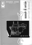
manuale di servizio
service manual
Promessa
4-5
6-7
Smontaggio carburatore
dal motore
Introduction
Removal of carburetor
from engine
Filtro a docantazlone
Coperchio carburatore
Fuel decantation filter
Carburetor cover
Galleggiante e valvola a spillo
Livellatura del galleggiante
8-9 Float and needle valve
Levelling of float
Getti principali
Tubetti emusionatori
Getti aria di freno
Rettifica sede di tenuta
getti principali
10-11 Main jets
Emulsioning tubes
Air corrector jets
Grinding of seat of main Jets
12-13
Gettt del minimo
Ispezioni viti registro
miscela minimo
Idling jets
Inspection of idling mixture
adjusting screws
Pompa di accelerazione
Montaggio stantuffo pompa
di accelerazione
Dispositivo avviamento
14-15 Accelerating pump
Assembling of accelerating
pump piston
Starter device
Rettifica e battitura
allogglamento
valvole avviamento
16-17 Grinding and riveting
of starter valves housing
Centratorl di miscela
e diffusori
Canalizzazioni
18-19 Chokes
and auxiliary ventur!
Pipe inspection
20-21
22-23 Throttle valves and shaft
Valvole a farfalla e alberino
CARBURATORI SERIE
CARBURETORS TYPE
DCOE
Montaggio alberino e valvole
a farfalia
shaft and throttle
24-25 Assembling
valves
indice generale
general index
Controllo corsa asta pompa
Anomalie di funzionamento
pump piston stroke
26-27 Check
Running faults
Assortimento ricambi
per revisione carburatori
Spare part assortments for
28-29 overhauling
carburetors
Attrezzatura Weber per la
revisione dei carburatori
tools
30-31 Weber
for overhauling carburetors
PREMESSA
INTRODUCTION
Scopo della presente pubblicazione e di fornire sia
all'Utente privato, sia al personate addetto alle
Stazioni di Servizio e Assistenza, un manuale di
servizio che possa rispondere alle necessita pratiche per le periodiche ispezioni e pulizie del carburatore.
Per rendere queste norme di facile attuazione, sono state illustrate le varie operazioni necessarie
per una corretta manutenzione del carburatore
trattando singolarmente i vari dispositivi che lo
costituiscono.
Questo genere di lavoro deve essere effettuato con
la massima cura per ottenere tutti i vantaggi che i
carburatori WEBER serie DCOE possono fornire.
Le norme indicate nella presente pubblicazione sono di carattere orientativo, in quanto non e sempre possibile procedere nell'ordine da noi indicato per lo smontaggio e rimontaggio dei complessivi dei carburatori, poiche cio e in funzione
defle necessita contingent!.
The purpose of this booklet is to supply to both
private users and to the maintenance Staff of Service Stations a service handbook which should meet
the practical needs of periodical service and cleaning of the carburetor.
In order to simplify these instructions, the various
operations necessary for the proper maintenance
of the carburetor have been described, and the
various devices which compose it have been individually dealt with.
This type of work must be done with the greatest care in order to enjoy all the benefits which
the WEBER DCOE series of carburetors can give.
The instructions given in this booklet are purely
of a general nature, as it is not always possible
to follow the order we have suggested for disassembling and assembling the carburetors, this
depending on the existing conditions.
Compito del carburatore
II solo ed unico compito specifico del carburatore
e quello di fornire una miscela di aria e carburante in proporzioni ben stabilite, fornendo al motore le quantita piu adeguate a seconda delle condizioni di funzionamento.
E' pertanto indispensabile, prima di addebitare al
carburatore eventuali difetti di funzionamento, controlIare lo stato di efficienza delle varie parti del
motore con particolare riguardo alla accensione
(grado di anticipo, candele, spinterogeno ecc.):
alia parte meccanica (compressione, registrazione
delle punterie, registrazione della distribuzione ecc.)
come pure alla qualita e al tipo dell'olio di lubrificazione del motore, che logicamente dovra essere quello indicato per le condizioni stagionaii di
impiego del veicolo.
Task of the carburetor
The one and only task of the carburetor is that
of delivering a mixture of air. and fuel in well defined proportions, supplying the engine with the
most suitable amounts in accordance with the running conditions.
Therefore, before blaming the carburetor for faults
in running, it is essential to check the efficiency
of the various parts of the engine especially as
regards the ignition system (advance, plugs, coil
ignition, etc.), the mechanical parts (compression,
valve tappet adjustment, timing adjustment, etc.)
and also the grade and type of lubricating oil
used, which naturally should be the one prescribed
for the seasonal conditions of use of trie vehicle.
Collaudo e regolazione
dei carburatori
Test and setting of carburetor
I carburatori WEBER della serie DCOE vengono forniti collaudati e provvisti della regolazione stabilita per I'autoveicolo cui sono destinati. Ogni manomissione e pertanto arbitraria e pub pregiudicare il regolare funzionamento del motore.
Consigliamo quindi di non apportare modifiche al
carburatore montato su vetture in origine dalla
Casa, salvo non esistano particolari disposizioni
emanate dai Servizi Tecnici interessati.
The WEBER DCOE series of carburetors are delivered tested and set as prescribed for the vehicle they
have been made for. No alteration of the setting
should consequently take place, as this might upset
the regular running of the engine. We suggest,
therefore, that no alterations should be introduced
into the setting of the carburetor as originally
assembled on the vehicle by the makers unless
the Technical Services concerned specify differently.
Assistenza
Salvo casi di impossibilita e sempre consigliabile
rivolgersi alle Stazioni di Servizio ed Officine Autorizzate WEBER, per la manutenzione e riparazione dei carburatori.
Assistance
Whenever possible, users requiring service or repairs to carburetors should apply to WEBER
Service Stations and Authorised Workshops.
4
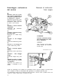
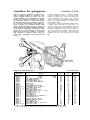
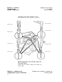
Smontaggio carburatore
dal motore
Removal of carburetor
from engine
1
Smontare il filtro aria o presa
aria e relativi collegamenti ai
carburatori (qualora cio possa effettuarsi in vettura)
Disconnect the air filter or air
intake and relative carburetor
connections (when this can
be clone in the vehicle)
2
Smontare il tirante comando
acceleratore
Disconnect the carburetor
connecting rod
3
Smontare il supporto ancoraggio presa d'aria
Disconnect air intake fixing
support
4
Allentare
guaina
la
vite fissaggio
ATTENZIONE
Smontati i carburatori proteggere I'imboccatura dei collettori di aspirazione
Loosen the sheath fixing screw
5
WARNING
Sbloccare la vite fissaggio filo
After removal of the carburetors, protect the manifold
suction port
Loosen cable fixing screw
6
Togliere il raccordo ingresso
benzina
Disconnect petrol pipe fitting
965O.12O.OOO1 bis (14)
7
Smontare
flangie
i
dadi
fissaggio
Disconnect flange fixing nuts
8
Smontare al banco, se necessario la presa di aria comune
ai carburatori
Disconnect the common air
intake, if necessary at the
bench.
All'atto del rimontaggio, che si effettua con procadimento inverso, prima di collegare il raccordo carburante, controllare lo stato di conservazione delle guarnizioni e la perfetta tenuta dei piani.
On re-assemb!ing, carried out by inverting the above procedure, check the state of gaskets and the flat
surfaces for perfect sealing before connecting fuel pipe.
5
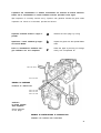
Filtro a decantazione
Fuel decantation filter
SMONTAGGIO E RIMONTAGGIO
DISASSEMBLING AND ASSEMBLING
Svitare il tappo del filtro
Remove the filter tap
Controllare la perfetta funzionalita della guarnizione
Check the perfect efficiency of the gasket
Accertarsi che la reticella filtrante non sia deformata
Make sure that filter gauze is not clamaqed
9650.120.0001 (18/19)
Piano di tenuta: controllare che la superficie non presenti intaccature
Condotto ingresso carburante da proteggersi
durante I'operazione di
pulizia del vano dt decantazione
Tightness: check that
surface has not been
scratched
Protect the fuel admission pipe during
cleaning of the filter
cavity
RIMONTARE con procedimento inverso dopo
aver alloggiato la reticella e boccola di ritegno nel vano del tappo, curando inoltre la
perfetta aderenza della guarnizione al piano
EFFETTUARE IL LAVAGGIO
CON BENZINA
di tenuta con adeguato serraggio.
E LA PULIZIA
CON ARIA COMPRESSA
RINSE IN PETROL
AND BLOW
OUT WITH
COMPRESSED AIR
ASSEMBLE with inverted procedure after
placing the gauze and retaining bush in the
tap housing, making sure also that the
gasket is in perfect contact with surface by
tightening the screws.
6
Carburetor cover
Coperchio carburatore
DISASSEMBLING AND ASSEMBLING
SMONTAGGIO E RIMONTAGGIO
A
ATTENZIONE
Smontaggio preventivo se necessario delle prese d'aria a
trombetta per i modelli che
ne sono muniti
Sollevare il coperchio con precauzione per evitare eventuali
deformazioni del galleggiante
Previous removing, if necessary, of air intake horns
where fitted.
W A R N I NG
Lift the cover carefully to avoid damaging the float
B
Smontare
il
coperchietto
ispezione getti svitando II
galletto a mano
9610.065.0039
Remove the jets inspection
cap
by
unscrewing
the
thumb-nut
C
Togliere le viti fissaggio coperchio
Remove cover fixing screws
D
Smontare la piastrina
Take off small metal plate
E
Togliere il coperchietto fondo
vaschetta
Take out well-bottom cap
9610.065.0039
Tappo ispezione filtro
Guarnizione per tappo
ispezione filtro
Reticella ftltrante
Filter inspection tap
Gasket for filter
inspection tap
Filter gauze
7
PARTICOLARI Dl
PIU' FREQUENTE SOSTITUZIONE
PARTS REQUIRING
FREQUENT REPLACEMENT
Viti fissaggio
coperchio carburatore
Carburetor cover
fixing screw
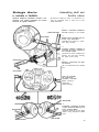
Galleggiante e
valvola a spillo
SMONTAGGIO E RIMONTAGGIO
II peso del galleggiante e elemento di regolazione
Riparazioni di fortuna (stagnature, ecc.) ne pregiudicano il funzionamento
Float and needle valve
DISASSEMBLING AND ASSEMBLING
The weight of the float is
a control element. Casual
repairs (tinning, etc.) will
influence its operation
9650.150.0083
Durante lo smontaggio
avere cura
di trattenere lo spillo
nella valvola
During disassembly
keep the needle
carefully in the valve
Posizione
di marcatura
Marking
position
Verificare la tenuta
Pulizia accurata
con aria compressa
a filtro smontato
Check sealing
Carefully clean
with compressed air
whilst filter
is disassembled
CONTROLLARE LO STATO
DI CONSERVAZIONE DELLA
GUARNIZIONE DEL COPERCHIO
Sfilare il perno fulcro e togliere il galleggiante
CHECK THE STATE OF PRESERVATION OF THE COVER
GASKET
Remove needle valve
PARTICOLARI DI
PIU' FREQUENTE SOSTITUZIONE
PARTS REQUIRING
FREQUENT REPLACEMENT
Remove the pivot and take out float
Smontare la valvola a spillo
Valvola a spillo
Guarnizione per coperchio carburatore
Guarnizione per valvola a spillo
Galleggiante
Perno fulcro galleggiante
Needle valve
Gasket for needle valve
Gasket for carburetor cover
Float
Float fulcrum pin
8
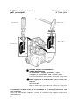
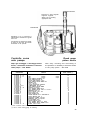
Livellatura del galleggiante
Tenere il eoperchio carburatore in posizione verticale. In queste condizioni la linguetta ( 1 ) deve
trovarsi a leggero contatto con la sfera ( 2 ) e contemporaneamente i due semigalleggianti ( 3 ) devono
trovarsi alla distanza A dal piano del coperchio
con guarnizione montata, a seconda del modello
del carburatore elencato nella tabella di livellatura.
Per il controllo usare I'apposito calibro Weber (indicato in tabella) le cui scanalature devono essere
poste in coincidenza delle costole ( 5 ) di unione dei
semigalleggianti. A livellatura effettuata controllare
che la corsa del galleggiante corrisponda a quella
prevista per il tipo di carburatore in esame. Vedi
tabella B. All'occorrenza modificare la posizione
delta linguetta ( 4 ) . Controllare inoltre, a fine operazione, che il galleggiante scorra liberamente sul
perno ( 6 ) .
Levelling of float
Hold the carburetor cover in a vertical position.
In these conditions the tab (1) must be in light
contact with the ball (2) and, at the same time,
the two semi-floats (3) must be A mm. from the
surface of the cover with gasket mounted, according to the model of carburetor, as listed in the
levelling table below.
For checking, use the special Weber gauge (shown
in table), taking care that its slots are in line
with the joints (5) of the semi-floats. After the
levelling has been clone, check that the stroke of
the float corresponds to the carburetor being examined. See Table B. If necessar adjust the position of the tab (4). Check also, at the end of the
operation, that the float runs freely on its pivot
(6).
9620.175.1990
9620.175.2909
TABELLA Dl LIVELLATURA
CARBURATORE
CARBURETOR
38
38
38
40
40
40
40
40
40
40
40
40
40
40
40
42
42
42
45
45
45
45
45
45
45
45
45
DCOE
DCOE
DCOE
DCOE
DCOE
DCOE
DCOE
DCOE
DCOE
DCOE
DCOE
DCOE
DCOE
DCOE
DCOE
DCOE
DCOE
DCOE
DCOE
DCOE
DCOE
DCOE
DCOE
DCOE
DCOE
DCOE
DCOE
13-14
16 - 17
25
2
2
2
4
8
9
18
20-21
24
25 - 26
27
28
8
12
12
9
9
9
9
9
12
13
14
15-16
LEVELLING TABLE
A(*)
VETTURA
VEHICLE
FIAT 2300/S Coupe
FIAT
2300/S
FIAT
2300/S
ALFA ROMEO GIULIETTA S.V
ALFA ROMEO GIUL1A S.S
LOTUS FORD ANGLIA 100 E
ALFA ROMEO GIULIA SPRINT G.T
PEUGEOT 404
A.S.A. 1000 G.T
LOTUS ELAN-FORD CORTINA
LAMBORGHINI 300 G.T. - 400 G.T
ALFA ROMEO GIULIA Super
RENAULT 8 Gordini
ALFA ROMEO SPRINT G.T.V
ALFA ROMEO GIULIA 1300 G.T. « Junior »
MASERATI 3500 G.T
B.P.M. ARCTIC 130 e 155
B.P.M. IONIC 125
ALFA ROMEO 2600
ASTON MARTIN D.B. 4 VANTAGE G.T
ASTON MARTIN D.B. 5
COVENTRY CLIMAX 1500 G.T
MASERATI 3500 G.T. Speciale
B.P.M. RACER 2500
AUSTIN HEALEY 3000
ALFA ROMEO GIULIA Til. Super - G.T.A
B.M.W. 1800 T.L./SA
mm.
Coupe
Coupe
8,5
7,5
8,5
8,5
8,5
8,5
8,5
7
7
8,5
8,5
8,5
8,5
8,5
8,5
5
7
7
7
5
7
5
5
7
8,5
8,5
7,5
( * ) Per le livellature sopraelencate, usare i calibri 9620.175.1990 e 9620.175.2909.
( * ) Use gauges 9620.175.1990 and 9620.175.2909 for the above levelling operations.
9
B
mm.
15
14
15
15
15
15
15
13,5
15
15
15
15
15
15
15
13,5
15
15
13,5
13,5
13,5
13,5
13,5
15
15
15
14
CORSA
STROKE
6,5
6,5
6,5
6,5
6,5
6,5
6t5
6,5
8
6,5
6,5
6,5
6,5
6,5
6,5
8,5
8
8
6,5
8,5
6,5
8,5
8,5
8
6,5
6,5
6,5
Getti principali
Tubetti emulsionatori
Getti aria di freno
Main jets
Emulsioning tubes
Air corrector jets
SMONTAGGIO E RIMONTAGGIO
DISASSEMBLING AND ASSEMBLING
9610.065.0O39
1
Smontaggio preventivo del coperchietto di protezione
First remove protection cap
Posizioni di
marcatura
2
Marking
position
Smontare i tubetti emulsionatori
Remove emulsioning tubes
3
Sfilare a mano i porta tubetti getti aria di freno getti principali
Take out tube holders - air
corrector jets - main jets by
hand
PARTICOLARI DI
PIU' FREOUENTE SOSTITUZIONE
PARTS REQUIRING
FREQUENT REPLACEMENT
Getti aria di freno
Getti principali
Air corrector jets
Main jets
10
Rettifica sede di tenuta
getti principali
9410.280.0014
Grinding of seat
of main jets
9650 355.0003 1
9610.315.0815
9600.325.0773
PULITURA POZZETTI ALLOGGIAMENTO
TUBETTI EMULSIONATORI
Si raccomanda di eseguire I'operazione a mano
CLEANING OF EMULSIONING TUBE HOUSING WELLS
It is recommended that this operation be carried out by hand
BATTITURA SEDI
Battere ieggermente la sede ruotando il perno centrale delI'attrezzo
SEAT RIVETING
Beat the seats lightly and rotate the central pin of the tool
AD OPERAZIONI ULTIMATE PULIRE 6LI ALLOGGIAMENTI E LE RELATIVE CONDUTTURE CON
ARIA COMPRESSA
WHEN THE OPERATION IS COMPLETE, CLEAN THE HOUSINGS AND RELATIVE DUCTS WITH
COMPRESSED AIR
11
Getto del minimo
Idling jets
SMONTAGGIO E RIMONTAGGIO
DISASSEMBLING AND ASSEMBLING
Smontaggio preventivo del coperchietto di prote-
First remove protection cap
Unscrew jet-holders.
zione
Svitare i portagetti
9610.065.0039
Posizione di marcatura
Marking position
Sfilare a mano
i getti del minimo
Slip out the idling jets
PULIZIA ACCURATA
CON ARIA
COMPRESSA
CAREFULLY CLEAN
WITH
COMPRESSED AIR
Rettifica sedi di tenuta
getti del minimo
Grinding and riveting of seats
of idling jets
9650.355.0003/1
RIPASSATURA SEDI
L'operazione deve essere eseguita a
mano
9610.280.0014
OVERHAULING OF SEATS
The operation must be done by hand
BATTITURA SEDI
Battere leggermente le sedi ruotando
il perno centrale dell'attrezzo
RIVETING OF SEATS
Beat the seals lightly and rotate the
centre! pin of the lool
AD OPERAZIONI ULTIMATE PULIRE
L'ALLOGGIAMENTO DEI GETTI DEL
MINIMO E LE RELATIVE CONDUTTURE CON ARIA COMPRESSA
WHEN THE OPERATIONS ARE COMPLETE, CLEAN THE HOUSING OF THE
IDLING JETS AND RELATIVE DUCTS
WITH COMPRESSED AIR
9600.325.0766
9610.315.0817
12
Inspection of idling mixture
adjusting screws
Ispezioni viti registro
miscela minimo
9610.065.0039
Controllare I'efficienza
della conicita delle viti
di registro
Check taper efficiency
of adjusting screws
Pulire mediante aria
compressa con getti
del minimo smontati
Clean with compressed
air with idling jets removed
Registrazione
del minimo
1/2 giro dalla posizione
di chiusura
1/2 turn from locking point
3/4 di giro dalla posizione di chiusura
3/4 turn from locking
9610.065.0039 point
Slow-running
adjustment
Effettuare
la
regolazione
provvisoria delle viti di registro
Carry out temporary setting
of the adjusting screws
Vite registro miscela minimo
Getti del minimo
Idling mixture adjusting screw
Idling jets
13
PARTICOLARI DI
PIU' FREQUENTE SOSTITUZIONE
PARTS REQUIRING
FREQUENT REPLACEMENT
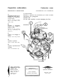
Pompa di accelerazione
SMONTAGGIO E RIMONTAGGIO
Accelerating pump
DISASSEMBLING AND ASSEMBLING
Accertarsi
della scorrevolezza
delta sfera
nella valvola
di aspirazione
9610.535.0035
9610.065.0039
9610.065.0039
9610.065.0038
Make certain
that ball
of inlet valve
slides freely
Posizione
di marcatura
Marking
position
Accertarsi delI a scorrevolezza delI a sfera e
premisfera valvola
mandata pompa.
Make certain of easy
movement of the ball
and ball-stop of pump
delivery valve
Posizione
di marcatura
Marking
position
PULIZIA ACCURATA DELLE SEDl E DEI CONDOTTI CON ARIA
COMPRESSA
CAREFULLY CLEAN SEATS AND
DUCTS WITH COMPRESSED AIR
14
Montaggio stantuffo pompa di accelerazione
Assembling of accelerating pump piston
Effettuare il rimontaggio tenendo
presente che la piastrina ritegno
molla va alloggiata a prestione
Re-assemble, keeping in mind that
spring retaining plate must be
pressed into seat.
9610.065.0039
ACCERTARSI
DEL
REGOLARE
SCORRIMENTO DELL'ASTA COMANDO STANTUFFC APRENDO
LE FARFALLE
CHECK FREE SLIDING OF PUMP
CONTROL SHAFT BY OPENING
THROTTLES
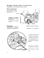
Dispositivo
avviamento (starter)
Starter device (starter)
SMONTAGGIO E RIMONTAGGIO
DISASSEMBLING AND ASSEMBLING
I carburatori tipo 42 DCOE 12
e 45 DCOE 12 sono sprovvisti
del dispositivo avviamento. II
vano dell'alloggiamento e pertanto chiuso da una piastrina
metallica.
Carburetor mod. 42 DCOE 12
and 45 DCOE 12 are not fitted
with starters so the housing
9610.065.0038
space is closed by a metal
plate
15
PER I MODELLI MUNITI Dl DISPOSITIVO AVVIAMENTO:
FOR MODELS FITTED WITH STARTER:
9610.065.0038
Direzione
caricamento
molla
Spring
stretching
direction
9650.150.0083
9610.065.0039
Posizione
corretta
degli alberini
settori
PULIZIA
CON ARIA COMPRESSA
Correct
position
of sector
spindles
CLEAN
WITH COMPRESSED AIR
16
Rettifica e battitura
alloggiamento
valvole avviamento
Grinding and riveting
of starter
valves housing
L'operazione deve essere eseguita a mano
The operation must be carried out by hand
9650.355.0003/1
9610.280.0014
9610.315.0820
9600.035.0422
9610.280.0014
9650.355.0003/1
9600.325.0815
9610.315.0817
Battere leggermente le sedi ruotando il perno centrale degli attrezzi
Lightly beat the seats, rotating the central pin
of the tools
Rettifica e battitura sedi
alloggiamento getti avviamento
17
Grinding and riveting ot starting jet
housing seats
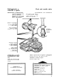
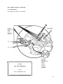
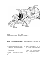
Centratori di miscela
e diffusori
SMONTAGGIO E RIMONTAGGIO
Auxiliary Venturis
and chokes
DISASSEMBLING AND ASSEMBLING
9610.150.0O3S
9610.150.0034
Posizione di
marcatura
Marking
position
Posizione di
marcatura
9610.065.0039
Marking
position
1 Smontaggio preliminare se necessario dei getti pompa
Preliminary disassembling, if necessary, of pump jets
2 Per i carburatori delI a serie 45 DCOE, smontare le viti di fissaggio
For carburetors of the 45 DCOE series, remove fixing screws
3
Estrarre i centratori di miscela e i diffusori mediante gli appositi attrezzi Weber
Extract the auxiliary Venturis and chokes with appropriate WEBER tools
18
Pipe inspection
Canalizzazioni
1
Canali del minimo
Idling ducts
2
Canali miscela minimo-progressione
Idle-progression mixture ducts
3
Canali awiamento
Starting ducts
4
Canali pompa di accelerazione
Accelerating pump ducts
ATTENZIONE
WARNING
NEI CARBURATORI 42 DCOE 12 - 45 DCOE 12
MANCA IL DISPOSITIVO DI A W I A M E N T O E
RELATIVE CANALIZZAZIONI
IN CARBURETORS 42 DCOE 1 2 - 4 5 DCOE 12
STARTER DEVICE AND RELATIVE DUCTS ARE
MISSING
19
L'ispezione alle canalizzazioni si effettua normalmente con iniezione di benzina. Nell'eventualita che la canalizzazione in esame risultasse ostruita, procedere come segue:
Pipe inspection is normally carried out by injection with gasoline. Should the pipes under
inspection be found to be blocked, proceed as follows:
a
Remove the lead plugs by boring
Ispezionare i canali mediante gli appositi utensili Weber
b
Inspect the pipes with the special Weber
tools
Pulire le canalizzazioni mediante energica soffiatura con aria compressa
c
Clean the pipes by blowing out energetically with compressed air
Asportare mediante foratura i tappi in
piombo
9650.355.0003/1
9610.315.0823
ESEMPIO DI ISPEZIONE
EXAMPLE OF INSPECTION
9620.175.1846
9620.175.1847
9620.175.1848
Verificare
la tenuta perfetta
della tappatura
Check tightness
of the plugs
ESEMPIO DI PASTIGLIATURA E PUNZONATURA
EXAMPLE OF PASTING AND PUNCHING
20
Valvole a farfalla
e alberino
Throttle valves and shafts
SMONTAGGIO E RIMONTAGGIO
1
DISASSEMBLING AND ASSEMBLING
Togliere le viti fissaggio valvole a farfalla
Remove the throttle-fixing screws
2
Sfilare le farfalle
Withdraw the throttles
3 Togtiere piattello ritegno moll a richiamo alberino
Take out spindle return spring retaining plate
9610.535.0034
4
Tolto il coperchietto, smontare spina connex leva comando
pom pa
9610.535.0033
After removing cap, take off pump control lever link pin
9610.535.0033
9610.065.0038
9650.355.0003/1
9610.535.0035
21
9610.065.0038
9610.065.0038
9650.150.0088
9650.150.0088
9650.355.0016022
5 Aprire le rosette di sicurezza
Open the tab washers
6 Smontare i dadi USANDO GLI APPOSITI ATTREZZI WEBER
Unscrew nuts USING APPROPRIATE WEBER TOOLS
7 Sfilare I'alberino completo di un cuscinetto
Withdraw spindle complete with a bearing
22
9650.355.0016 0 22
9610.315.0959
3 Smontare a mano leva o rosetta, coperchietti, mode e copripolvere
Take off lever or washer, caps, springs and dustcovers by hand
9 Con piazzamento in morsa, sfilare I'alberino dal cuscinetto
By placing in a vice, draw out spindle from bearings
10 Rimontare il solo alberino nel corpo e quindi smontare l'altro cuscinetto
Re-assemble the spindle alone in the body and then disassemble
the other bearing.
9650.355.0016022
23
Assembling shaft and
throttle valves
Montaggio alberino
e valvole a farfalla
Should the shaft be worn or deformed, it
may be replaced with a new one of the
same diameter
Qualora I'alberino risultasse usurato o deformato, puo essere sostituito con nuovo
alberino di uguale diametro
1
Montare il cuscinetto nell'alberlno
9650.355.0016022
Assemble bearing in the spindle
2
9610.315.0956
Montare I'altro cuscinetto nella sede del corpo carburatore
Assemble other bearing in carburetor body housing
3
Introdurre I'alberino complete di
cuscinetto, nel corpo, inserendo la
leva comando pompa
Introduce the shaft, complete with
bearing, into the body, inserting
the pump control lever
9610.315.0956
4
Montare i copripolvere con apposito attrezzo
Put on the dustcovers with special
tool
9610.315.0957
Prima del montaggio
del copripolvere
ingrassare i cuscinetti
Before mounting
dustcovers,
grease bearings
9610.065.0038
5
Completare il montaggio da ambo
le parti utilizzando sempre gli appositi strumenti Weber
Complete assembly on both sides,
always using appropriate Weber
tools
9650.150.0088
9610.065.0038
9650.150.0088
24
9620.175.2555
9610.535.0034
9610.020.0507
2410.176.0812 0 2
9610.280.0006/2
9610.535.0035
9610.315.0958
9610.065.0038
9610.535.0033
9650.355.0003/1
6
8
7
Montare spina connex leva comando pompa
Montare la molla e relativo plattello di ritegno
Assemble pump control lever link
pin
Assemble spring and relative retaining plate
Montare le valvolc a farfalla
Assemble the throttle valves
IN CASO DI SOSTITUZIONE DEU'ALBERINO
SHOULD REPLACEMENT OF THE SPINDLE BE
PROCEDERE ALLA FORATURA COL SEGUENTE
NECESSARY CARRY OUT BORING IN THE
PROCEDIMENTO:
FOLLOWING MANNER:
a - fissare la posizione esatta del la leva sulI'alberino con I'apposito attrezzo Weber
a - decide on exact position of lever on
shaft by means of appropriate Weber
tool
b - portare la leva alia posizione di corsa
mediante I'apposito calibro Weber da
fissare al corpo
c - eseguire la foratura con punta ad elica
0 2
23
b - put the lever into the running position
by means of the appropriate Weber
gau ge to be mounted on the body
c - carry out boring with 0 2 twist drill
9610.315.0833
Assicurare il dado piegando
I'apposita linguetta
Secure nut by bending
appropriate tab.
9610.535.0035
Aggraffare le viti e controllare la
scorrevolezza defl'alberino agendo
sulia leva
Countersink the screws and check,
by acting on the lever, the smooth
movement of the spindle
Controllo corsa
asta pompa
Check pump
piston stroke
Dopo ogni montaggio e rimontaggio dell'alberino, e necessario controllare la corsa delI'asta pompa - vedi tabella
CARBURATORE
CARBURETOR
38
38
38
40
40
40
40
40
40
40
40
40
40
40
40
42
42
42
45
45
45
45
45
45
45
45
45
45
DCOE
DCOE
DCOE
DCOE
DCOE
DCOE
DCOE
DCOE
DCOE
DCOE
DCOE
DCOE
DCOE
DCOE
DCOE
DCOE
DCOE
DCOE
DCOE
DCOE
DCOE
DCOE
DCOE
DCOE
DCOE
DCOE
DCOE
DCOE
13 - 14
16 - 17
25
2
2
2
4
8
9
18
20-21
24
25 - 26
27
28
8
12
12
9
9
9
9
9
12
13
14
14
15 - 16
After every mounting and re-mounting of
the spindle it is necessary to check the stroke
of the pump piston - see table
VETTURA
VEHICLE
FIAT 2300/S Coupe
FIAT
2300/S
FIAT
2300/S
ALFA ROMEO G1ULIETTA S.V
ALFA ROMEO GIULIA S.S
LOTUS FORD ANGLIA 100 E
ALFA ROMEO GIULIA SPRINT G.T
PEUGEOT 404
A.S.A. 1000 G.T
LOTUS ELAN-FORD CORTINA
LAMBORGHINI 350 G.T
ALFA ROMEO GIULIA SUPER
RENAULT 8 Gordini
ALFA ROMEO SPRINT G.T.V
ALFA ROMEO GIULIA 1300 G.T. « Junior »
MASERATI 3500 G.T
B.P.M. ARCTIC 130 e 155
B.P.M. IONIC 125
ALFA ROMEO 2600
ASTON MARTIN D.B. 4 VANTAGE G.T
ASTON MARTIN D.B. 5
COVENTRY CLIMAX 1500 G.T
MASERATI 3500 G.T. Speciale
B.P.M. RACER 2500
AUSTIN HEALEY 3000
ALFA ROMEO GIULIA T.I. Super
ALFA ROMEO GIULIA SPRINT G.T.A.
B.M.W. 1800 T.I./S.A
CORSA POMPA ( * )
PUMP STROKE ( * )
Coupe
Coupe
14
14
14
14
14
10
14
10
10
10
10
14
10
14
14
10
14
14
10
10
10
10
10
14
10
10
10
14
(*) Per iI controllo usare un nor male calibro a corsoio.
( * ) Use a normal sliding gauge for checking.
26
ANOMALIE Dl F U N Z I O N A M E N T O
RUNNING FAULTS
A) DIFFICOLTA' Dl AVVIAMENTO A MOTORE FREDDO
A) ENGINE WILL NOT START FROM COLD
CONTROLLARE:
CHECK:
— IMPIANTO ELETTRICO Dl ACCENSIONE: in genere
— CANDELE: distanza elettrodi
— OLIO Dl LUBRIFICAZIONE:
alle indicazioni del I a Casa
— ELECTRICAL EQUIPMENT: generally
— PLUGS: gap between paints
deve
corrispondere
— LUBRICATING OIL:
recommendations
must correspond to maker's
— DISPOSITIVO Dl AVVIAMENTO: con pomello tirato a fondo corsa il dispositivo deve risultare
inserito
— STARTER DEVICE: pulling the starter knob full
ont the device must be switched on
— MINIMO: normale registrazione
— SLOW RUNNING: normal adjustment
Non premere il pedale dell'acceleratore durante I'avviamento a mot ore freddo.
B) DIFFICOLTA' Dl
AVVIAMENTO A MOTORE CALDO
Effettuare i controlli come indicato in ( A ) considerando che in questo caso NON SI DEVE USARE IL DISPOSITIVO Dl AVVIAMENTO; quindi pomello in posizione
di riposo.
L'avviamento difettoso puo essere causato anche da
forte evaporazione del carburante in vaschetta dovuta
a surriscaldamento del mo tore: si vengono a formare
in questo caso vapori di carburante che si raccolgono
nel filtro aria e nelle condutture provocando I'ingolfamento del motore. E' PERTANTO NECESSARIO PREMERE IL PEDALE DELL'ACCELERATORE FINO A META' CORSA, tenendolo fermo in tale posizione mentre si effettua l'avviamento.
C) MINIMO IRREGOLARE
B) ENGINE WILL NOT START FROM HOT
Carry out operations mentioned in ( A ) keeping in
mind that the STARTING DEVICE MUST NOT BE
USED; therefore, starter knob will be in the idling
position.
Defective starting may also be caused by great evaporation in the bowl due to over-heating of the engine: in this way fuel vapour is formed which gathers in the air filter and pipes, so causing flooding
of the engine. IT IS THEREFORE NECESSARY TO
PRESS THE ACCELERATOR PEDAL half-way, holding
that position whilst carrying out the start.
C) IRREGULAR SLOW RUNNING
CONTROLLARE:
CHECK:
— GUARNIZIONI: poste fra collettore e testa motore
— GASKETS:
between
manifold
— GASKETS:
between
manifold and carburetor
— GUARNIZIONI: poste fra collettore e carburatore
— GETTO MINIMO: dati di taratura-pulizia, ispezione canalizzazioni-serraggio getti sul carburatore
— DISPOSITIVO AVVIAMENTO: non debbono esistere
infiltrazioni di miscela. Ispezionare la valvola del
dispositivo controllandone la tenuta; ispezionare
il cavetto comando avviamento che in posizione
di riposo NON DEVE trattenere aperta la valvola
— FARFALLE DEL CARBURATORE: devono ritornare
nelIa posizione di minimo con pedale dell'acceleratore a riposo. Controllare quindi che gli organi
di comando non presentino resistenza al movimento
— ANTICIPO: quello previsto dalla Casa
27
When starting the engine from cold, do not depress
the accelerator pedal
and cylinder head
— IDLING JET: setting-cleaning, inspection of pipes
and proper tightness of jets on the carburetor
— STARTER DEVICE: there must be no infiltration
of mixture. Inspect the valve of the device for
tightness; inspect starter control cable which,
at rest, MUST NOT keep the valve open.
— THROTTLES: they must return to idling position
when the accelerator pedal is at rest. Then check
that control parts are not causing any stiffness
of movement
— ADVANCES: as indicated by the maker
— IMPIANTO ELETTRICO E D'ACCENSIONE: in generate
— ELECTRICAL
general
AND
STARTING
— CANDELE: distanza elettrodi - tipo prescritto dalla Casa.
— PLUGS: gap
by maker
between
points
EQUIPMENT:
type
in
recommended
D) FLOODING AND FUEL LEAKAGE
D) INGOLFAMENTO E PERDUE Dl CARBURANTE
CONTROLLARE:
CHECK:
— VALVOLA A SPILLO: stato d'uso
— NEEDLE VALVE: wear
— GALLEGGIANTE: stato d'uso
— FLOAT: wear
— LIVELLATURA DEL GALLEGGIANTE:
relative a pag. 9.
vedi
norme
— FLOAT LEVELLING: see instruction on cage 9.
— ELIMINARE EVENTUALI ATTRITI CHE OSTACOLINO IL REGOLARE MOVIMENTO DEL GALLEGGIANTE O IMPURITA' CHE BLOCCHINO LO SPILLO ENTRO LA SUA GUIDA
— ELIMINATE ANY FRICTION INTERFERING WITH
THE REGULAR MOVEMENT OF THE FLOAT OR
ANY IMPURITY BLOCKING THE NEEDLE IN ITS
GUIDE
— GUARNIZ1ONI: dei getti principal;
ispezione filtro (stato d'uso)
— GASKETS:
(wear)
- del
tappo
E) MANCANZA Dl RIPRESA E VELOCITA'
IL VEICOLO DEVE AVERE EFFETTUATO IL NORMALE RODAGGIO (in genere 4-5000 Km.)
CONTROLLARE:
main
jets and filter inspection
plugs
E) ENGINE LACKS ACCELERATION AND SPEED
THE VEHICLE MUST. HAVE COMPLETED THE
RUNNING-IN MILEAGE (generally 4-5000 Km.)
CHECK:
— IMPIANTO ELETTRICO Dl ACCENSIONE: in genere
— ELECTRICAL EQUIPMENT: generally
— ORGANI DEL MOTORE: stato d'uso in genere
— ENGINE PARTS: general wear
— REGOLAZIONE CARBURATORE: consultare la tabella regolaziont
— LIVELLATURA DEL GALLEGGIANTE:
relative a pag. 9.
vedi
— CARBURETOR
table
ADJUSTMENT:
consult
adjustment
norme
— FLOAT LEVELLING: see instruction on page 9.
— GETTI PRINCIPAL!: pulizia
— MAIN JETS: clean
— FARFALLE DEL CARBURATORE: con pedale delI'acceleratore a fondo corsa le farfalle DEVONO
APRIR5I completamente
— THROTTLES: that throttles are COMPLETELY
OPEN when accelerator pedal is fully depressed
— ANTIC1PO: quello previsto dalla Casa
— ADVANCE: as indicated by the maker
— ORGANI Dl FRENATURA DEL VEICOLO E FRIZIO
NE: eliminare eventuali inceppamenti negli organi di frenata. Accertarsi inoltre che la frizione
non tenda a slittare.
— BRAKING EQUIPMENT AND CLUTCH: eliminate
any possible jamming in the braking equipment.
Make sure also that the clutch does not tend to
slip
F) EXCESSIVE CONSUMPTION
F) CONSUMO ECCESSIVO
CONTROLLARE:
CHECK:
— ORGANI DEL MOTORE: lo stato d'uso in genere
— REGOLAZIONE DEL CARBURATORE: quella prescritta dalla Casa costruttrice dell'autoveicolo
— DISPOSITIVO AVVIAMENTO: effettuare i controlli
del punto ( B )
— VALVOLE DEL DISPOSITIVO DI AVVIAMENTO:
non debbono permettere trafilamenti o perdite
— ENGINE PARTS: general wear
— CARBURETOR ADJUSTMENT: as prescribed by the
maker of the vehicle
— STARTER DEVICE: carry out the checks in (B)
— STARTER DEVICE VALVE:
must be allowed
no losses or leakage
— VALVOLA A SPILLO: tenuta perfetta
— NEEDLE VALVE: perfectly tight
— GALLEGGIANTE: in perfetto stato d'uso
— FLOAT:
— LIVELLATURA GALLEGGIANTE: vedi norme relative a pag. 9.
— IMPIANTO ELETTRICO Dl
nere
ACCENSIONE:
in ge
for perfect condition
— FLOAT LEVELLING: see instruction on page 9.
— ELECTRICAL EQUIPMENT: generally
— ANTICIPO: quetlo previsto dalla Casa
— ADVANCE: as indicated by the maker
— CARTUCCIA FILTRO ARIA: in perfette condizioni d'uso e possibilmente originate.
— AIR FILTER CARTRIDGE: for perfect
and that it is, preferably, original
condition
28
ASSORTIMENTO RICAMBI PER REVISIONE CARBURATORI
SPARE PART ASSORTMENTS FOR OVERHAULING CARBURETORS
ASSORTIMENTO
GASKET KIT
GUARNIZIONI
ASSORTIMENTO NORMALE
TUNE-UP KIT
N.B. - Nelle ordinazioni indicare: tipo del carburatore e matricola dell'assortimento.
Le scatole assortimenti vengono fornite solamente complete.
N.B. - When ordering assortment boxes, kindly indicate the model of the carburetor and its number.
Assortment boxes are supplied only complete, as shown above.
RIVOLGERSI SEMPRE ALLA ORGANIZZAZIONE Dl VENDITA ED ASSISTENZA WEBER OPPURE ALLE FlLIALI ED AGENZIE Dl ZONA DELLA CASA COSTRUTTRICE DEL VEICOLO ESISTENTI NEI PRINCIPALI
CENTR1 ITALIANI ED ESTERI.
ALWAYS APPLY TO THE WEBER SALES ORGANISATION OR TECHNICAL SERVICES, OR TO THE BRANCHES
OR LOCAL AGENCIES OF THE VEHICLE MANUFACTURER TO BE FOUND IN THE MAIN CENTRES IN
ITALY AND ABROAD.
29
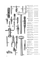
ATTREZZATURA WEBER
PER LA REVISIONE
DEI CARBURATORI
WEBER TOOLS FOR
OVERHAULING
CARBURETORS
1
Attrezzo per montare
coprfpolvere
Too! for mounting dustcover
9610.315.0957
2
Alesatore per ripassatura
condotto valvola awlamento
Reamer for overhauling
starter valve duct
9600.035.0422
Cacciavite grande
Large screwdriver
Cacciavite grande
Large screwdriver
9610.065.0038
4
Attrezzo per montare
cuscinetfo nel corpo
carburatore
Tool for mounting bearing
on carburetor body
9610.315.0956
5
6
Pin2a a becco mezzo tondo
Half-rounded pliers
9610.535.0034
3
Chiave fissa
Fixed spanner
Chiave fissa
Fixed spanner
Chiave fissa
Fixed spanner
Chiave fissa
Fixed spanner
Chiave fissa
Fixed spanner
Chiave fissa
Fixed spanner
Chiave fissa
Fixed spanner
9610.065.0039
9650.120.0001 (6/7)
I9650.120.0001 bis (7)
I9650.120.0001 bis (8)
'
j9650.120.0001 bis (10)
9650.120.0001 bis (12)
{9650.120.0001 bis (14)
9650.120.C001 bis (18/19)
9610.315.0959
7
Attrezzo per smontare
cuscinetto dall'alberino
Tool for disassembling
bftaring from spindle
8
9
Chiave a tubo - esag. 14/15 9650.150.0084
Hexagonal box spanner 14/15
10
11
12
13
IPT
Chiave a T - esag. 8-10-12 9650.150.0083
Hexagonal T wrench 8-10-12
Chiave speclale esagonale
Special hexagonal spanner
9650.150.0088
Attrezzo per foratura
alberino
Tool for boring spindle
9610.020.0507
Calibro controllo llvellatura
galleggiante
Gauge for checking float
levelling
Calibro controllo livellatura
galleggiante
Gauge for checking float
levelling
9620.175.2909
9620.175.1990
Calibro 0 1
9620.175.1846
controllo canalizzazlonl
Gauge 0 1 for checking ducts
Calibro 0 1,5
9620.175.1847
controllo canalizzazlonl
Gauge 0 1.5
for checking ducts
Calibro 0 2
9620.175.1848
controllo canallzzazlonl
Gauge 0 2 for checking ducts
14
15
Estrattore per dlffusorl
Extractor for choke
9610.150.0034
Estrattore per centratorl
dl miscela
Extractor for auxiliary
venturl
9610.150.0035
16
Filiera
Screw
Fillera
Screw
Flliera
Screw
Filiera
Screw
Filiera
Screw
Hllera
Screw
2116.021.0712
2116.029.0712
2116.036.0712
2116.041.0712
2116.047.0712
2116.057.0712
0 4x07
die 0 4 x 0.7
0 5x0,8
die 0 5x0.8
0 6x1
die 0 6 x 1
0 7x1
die 0 7 x 1
0 8x1
die 0 8 x 1
0 10 x 1
die 0 1 0 x 1
30
17
Punzone per smontagglo
spina conrtex 0 2
Punch for disassembling link
pin 0 2
S810.315.0958
18
Glramaschl da mm. 4
a mm. 10
Tap wrench from 4 to 10 mm
9600.200.0013
19
20
Martello da 100 grammi
Hammer of 100 gms.
9650.355.0003/1
Maschio III 0 4 x 0r7
Screw tap III 0 4 x 0.7
Maschio III 0 5x0,8
Screw tap i l l 0 5 x 0.8
Maschio Ml 0 6 x 1
Screw tap 111 0 6 x 1
Maschio III 0 7 x 1
Screw tap III 0 7 x 1
Maschio III 0 8 x 1
Screw tap III 0 8 x 1
Maschio III 0 10 x 1
Screw tap III 0 10 x 1
2200.063.0808
2200.087.0808
2200.108.0808
2200.123.0808
2200.141.0808
2200.171.0808
Mandrino porta punte
da mm. 0 a mm. 1,5
Chuck for twist drills
from 0 to 1.5 mm
Mandrino porta punte
da mm. 1 a mm. 3
Chuck for twist drills
from 1 to 3 mm
9610.280.0006/1
22
Impugnatura con mandrino
porta punte
Holder with chuck
for twist drills
9610.280.0014
23
Punzone per battitura
sede getto minimo
Punch for idling jet seat
9610.315.0816
24
Punzone per battitura
sede getto principal
Punch for main jet seat
9610.315.0815
25
Punzone per battitura sede
valvola avviamento
Punch for starting valve seat
9610.315.0820
26
27
Punzone per tappature
Punch for plugs
9610.315.0823
Punzone per aggraffatura vltl
Punch for countersinking
screws
9610.315.0833
21
28
Punta per ripassatura
condotto getto minimo
Flat drill for overhauling
idle jet duct
29
Punta per ripassatura
condotto getto principate
Flat drill for overhauling
main jet duct
30
Punta per ripassatura
condotto getto avviamento
Reamer for overhauling
starter jet duct
9600.325.0815
31
GlrafiMera a tubo
Tube dlestock
Glrafiliera a tubo
Tube dlestock
9610.360.0075
9610.360.0076
32
33
34
Raschietto triango are
Triangular scraper
9600.375.0013
Pinza a becco platto
Flat pliers
9610.535.0035
Serie punte elicoidali
da mm. 0,40 a mm. 2,35
Series of twist drills from
mm. 0,40 to 2,35 mm.
2410.176.0812
Serie tamponcini
Set of mlcrom plugs
9620.150.0016
Pinzette elastiche
Tweezers
9610.535.0033
Calibro per foratura alberino
Gauge for boring spindle
9620.175.2555
Martello In plastica
Plastic hammer
9650.355.0016 0 22
35
36
37
38
31
9610.280.0006/2
9600.325.0766
9600.325.0773