1
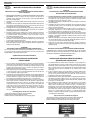
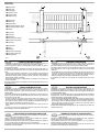
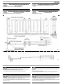
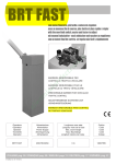
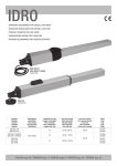
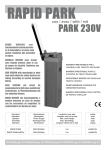
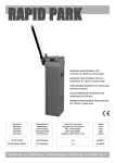
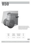
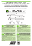
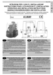
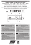
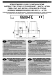
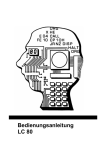
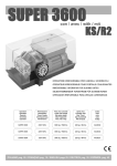
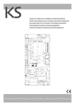
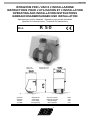
Pag. 1 di 16
ISTRUZIONI PER L'USO E L’INSTALLAZIONE
INSTRUCTIONS POUR L'UTILISATION ET L’INSTALLATION
OPERATING AND INSTALLATION INSTRUCTIONS
GEBRAUCHSANWEISUNGEN UND INSTALLATION
Operatore per portoni industriali - Operateur pour portails industriels
Operator for industrial doors - Torantrieb für Industrietore
R 50
Mod.
Misure in mm
Mesures en mm
Measurements in mm
Abmessungen in mm
Fig. 1
Operatore
Operateur
Operator
Torantrieb
R50
Alimentazione
Alimentation
Power Supply
Stromspannung
230V - 50/60Hz
Peso max cancello
Poids maxi du portail
Max gate weight
Max Torgewicht
2000Kg / 4460lbs
®
automatismi per cancelli
automatic entry systems
codice
code
code
code
AA21580
Pag. 2 di 16
I
IMPORTANTI ISTRUZIONI PER LA SICUREZZA
F
INSTRUCTIONS IMPORTANTES POUR LA SECURITE
- ATTENZIONE É IMPORTANTE PER LA SICUREZZA DELLE PERSONE CHE VENGANO SEGUITE
TUTTE LE ISTRUZIONI
- ATTENTION IL EST IMPORTANT POUR LA SECURITE DES PERSONNES DE SUIVRE
ATTENTIVEMENT TOUTES INSTRUCTIONS
1° - Questo libretto d'istruzioni è rivolto esclusivamente a del personale
specializzato che sia a conoscenza dei criteri costruttivi e dei dispositivi di
protezione contro gli infortuni per i cancelli, le porte e i portoni motorizzati (attenersi
alle norme e alle leggi vigenti).
2° - L’installatore dovrà rilasciare all’utente finale un libretto di istruzioni in accordo alla
EN 12635.
3° - L’installatore prima di procedere con l’installazione deve prevedere l’analisi dei rischi
della chiusura automatizzata finale e la messa in sicurezza dei punti pericolosi
identificati (seguendo la norma EN 12453/EN 12445).
4° - Il cablaggio dei vari componenti elettrici esterni all’operatore (ad esempio fotocellule,
lampeggianti, ecc.) deve essere effettuato secondo la EN 60204-1 e le modifiche a
questa apportate dal punto 5.2.2 della EN 12453.
5° - L’eventuale montaggio di una pulsantiera per il comando manuale del movimento
deve essere fatto posizionando la pulsantiera in modo che chi la aziona non si trovi
in posizione pericolosa; inoltre si dovrà fare in modo che sia ridotto il rischio di
azionamento accidentale dei pulsanti.
6° - Tenete i comandi dell'automatismo (pulsantiera, telecomando etc.) fuori dalla portata
dei bambini. I comandi devono essere posti ad un’altezza minima di 1,5mt dal suolo
e fuori dal raggio d’azione delle parti mobili.
7° - Prima di eseguire qualsiasi operazione di installazione, regolazione, manutenzione
dell’impianto, togliere la tensione agendo sull’apposito interruttore magnetotermico
collegato a monte dello stesso.
1° - Ce manuel d'instruction est adressé seulement au personnel specialisé qui a
une connaissance des critères de construction et des dispositifs de protection contre
les accidents en ce qui concerne les portails, les portes et les portes cochères
motorisées (suivre les normes et les lois en vigueur).
2° - L’installateur devra remettre, à l’utilisateur final, une notice technique conformément
à la norme EN12635.
3° - L’installateur doit avant de procéder à l’installation, prévoir l’analyse des risque de
l’automatisation finale et la mise en sécurité des zones dangereuses identifiées
(selon la norme EN 12453/12445).
4° - Le câblage des différents éléments électriques externes à l’opérateur (ex.
photocellules, clignotants, etc…) doit être effectué selon la norme EN 60204-1 et
aux modifications apportées au paragraphe 5.2.2 de la norme EN 12453
5° - La pose éventuelle d’une commande manuelle par bouton pour la mise en marche
de l’automatisme ne doit pas être positionnée dans une zone qui mettrait en danger
l’opérateur ; il est également important de l’installer de sorte à éviter toute action
accidentelle des boutons.
6° - Gardez les commandes de l'automatisme (boutons poussoirs, télécommande etc.)
hors de la portée des enfants. Les commandes doivent être placées au minimum à
1,5 m du sol, et hors de rayon d’action des pièces mobiles.
7° - Avant d’exécuter quelconques opérationd’installation, réglage, entrietien de
l’installation, couper la tension avec l’interrupteur magnétothermique approprié
connecté en amont.
- ATTENZIONE UNA SCORRETTA INSTALLAZIONE PUÓ PORTARE A DANNI RILEVANTI
LA DITTA RIB NON ACCETTA NESSUNA RESPONSABILITÀ per eventuali danni
provocati dalla mancata osservanza nell'installazione delle norme di sicurezza, delle
leggi attualmente in vigore e delle istruzioni stesse.
- ATTENTION UNE INSTALLATION INCORRECTE PEUT CAUSER DE GRANDS DOMMAGES
L'ENTREPRISE R.I.B. N'ACCEPTE AUCUNE RESPONSABILITÉ pour des dommages
éventuels provoqués par le manque d'observation lors de l'installation des normes de
sécurité de lois actuellement en vigueur et des instructions même.
CONSERVARE CON CURA QUESTE ISTRUZIONI
GARDER MODE D’EMPLOI
IMPORTANTI ISTRUZIONI DI SICUREZZA PER
L’INSTALLAZIONE
INSTRUCTIONS TRÈS IMPORTANTES EN MATIÈRE DE
SÉCURITÉ POUR L'INSTALLATION
1° - Se non é previsto nella centralina elettrica, installare a monte della medesima
un'interruttore di tipo magnetotermico (onnipolare con apertura minima dei contatti
pari a 3mm) che riporti un marchio di conformità alle normative internazionali. Tale
dispositivo deve essere protetto contro la richiusura accidentale (ad esempio
installandolo dentro quadro chiuso a chiave).
2° - Per la sezione ed il tipo dei cavi la RIB consiglia di utilizzare un cavo di tipo H05RNF con sezione minima di 1,5mm2 e comunque di attenersi alla norma IEC 364 e alle
norme di installazione vigenti nel proprio Paese.
3° - Posizionamento di un’eventuale coppia di fotocellule: Il raggio delle fotocellule deve
essere ad un’altezza non superiore a 70 cm dal suolo e ad una distanza dal piano di
movimento dell’anta non superiore a 20 cm. Il loro corretto funzionamento deve
essere verificato a fine installazione in accordo al punto 7.2.1 della EN 12445.
4° - Per il soddisfacimento dei limiti imposti dalla EN 12453, se la forza di picco supera il
limite normativo di 400 N è necessario ricorrere alla rilevazione di presenza attiva
sull’intera altezza del cancello (fino a 2,5m max) - Le fotocellule in questo caso sono
da applicare all’esterno tra le colonne ed all’interno per tutta la corsa della parte
mobile ogni 60÷70cm per tutta l’altezza delle colonne del cancello fino ad un
massimo di 2,5m (EN 12445 punto 7.3.2.1) - es. colonne alte 2,2mt => 6 coppie di
fotocellule - 3 interne e 3 esterne (meglio se dotate di sincronismo - 6 FIT SYNCRO
con 2 TX SYNCRO).
1° - Si la centrale électrique ne dispose d'aucun interrupteur, il faut en installer un de
type magnétothermique en amont de cette dernière (omnipolaire avec ouverture
minimale des contacts correspondant à 3mm); la marque de cet interrupteur devra
être en conformité avec les normes internationales. Ce dispositif doit être protégé
contre toute remise en fonction accidentelle (ex. en l’installant dans un coffre
fermant à clé).
2° - En ce qui concerne la section et le type des câbles, le conseil de la RIB est celui
d'utiliser un câble de type H05RN-F présentant une section minimale de 1,5mm2 et,
quoi qu'il en soit, de se conformer à la norme IEC 364, ainsi qu'aux normes
d'installation en vigueur dans le pays de destination.
3° - Positionnement d’un éventuel jeu de photocellules : le faisceau des photocellules ne
doit pas être à une hauteur supérieure à 70 cm du sol et 20 cm du bord du vantail.
Leur correct effectivité fonctionnement doit être vérifié terminant l’installation, selon
le point de la 7.2.1 de la EN 12445.
4° - Afin de satisfaire aux limites imposées par la norme EN 12453, si la force d’impact
dépasse la limite de 400N, il sera nécessaire de détecter une présence sur la
hauteur totale du portail (jusqu'à un maximum de 2,5m) - Les cellules photoélectriques dans ce cas-ci doivent être s'appliquent extérieurement entre les colums
et intérieurement pour toute la course de la pièce de mobil chaque 60÷70cm pour
toute la taille de la colonne de la porte jusqu'à un maximum de 2,5m (EN 12445
point 7.3.2.1) - exemple: taille 2,2m de colonne = > 6 copies des cellules photoélectriques - 3 internes et 3 externes (meilleur si complet du dispositif de syncronism
- FIT SYNCRO avec TX SYNCRO).
N.B.:É obbligatoria la messa a terra dell'impianto
I dati descritti nel presente manuale sono puramente indicativi.
La RIB si riserva di modificarli in qualsiasi momento.
Realizzare l’impianto in ottemperanza alle norme ed alle leggi vigenti.
N.B.:La mise à terre de l'installation est obligatoire.
Les données figurant dans le présent manuel sont fournies à titre purement indicatif.
La RIB se réserve le droit de les modifier à tout moment, sans aucun préavis.
Effectuer l'installation en conformité avec les normes et les lois en vigueur.
Pag. 3 di 16
GB
IMPORTANT SAFETY INSTRUCTIONS
D
WICHTIGE ANWEISUNGEN FÜR DIE SICHERHEIT
- WARNING IT IS IMPORTANT FOR THE SAFETY OF PERSONS TO FOLLOW ALL
INSTRUCTIONS
- ACHTUNG UM DIE SICHERHEIT VON PERSONEN VOLLKOMMEN
GARANTIEREN ZU KöNNEN, IST ES WICHTIG, DASS ALLE
1° - This instruction booklet is exclusively dedicated to specialized staff who are
aware of the construction criteria and of the accident prevention protection devices
for motorized gates and doors (according to the current regulations and laws).
2° - In the compliance with the EN 12635, the fitter must issue an istruction manual.
3° - Even before beginning with the installation, fitters must examine the risks of an
automatic closing and find an appropriate solution for these cases (in accordance
with the EN 12453 and EN 12445).
4° - All external electrical wirings to the operators (e.g. photocells, blinkers etc.) must be
carried out in compliance with the EN 60204-1 norm and their subsequent
modifications brought to them with the point 5.2.2 of the EN 12453.
5° - When a command pushbutton is also installed, it is necessary that the istallation is
carried out in such a way that the operator is in a safe position, and so to reduce to a
minimum the risks of accidental operation.
6° - Keep the automatic control (push-button, remote control, etc) out of the reach of
children. The control systems must be installed at a minimum height of 1.5m from
the ground surface and not interfere with the mobile parts.
7° - Before starting any installation and operation or maintenance work make sure to cut
off power supply by turning the general magnetothermic switch off.
1° - Diese Montageanweisung ist ausschließlich für geschultes Fachpersonal
bestimmt, das mit den Montagevorschriften und den Schutzvorrichtungen zur
Verhinderung von Unfällen bei motorisierten Toren vertraut ist (nach den aktuellen
Normen und Gesetzen).
2° - In Uebereistimmung mit der EN12635, aus dem selbigen Handbuch.
3° - Bevor sie mit der installation beginnen,muessen sie eine geeignete Schutzfunktion
fuer das automatische Schliessen finden(immer in Anlehnung an die EN 12453 und
EN12445).
4°- Alle externen elektrischen Kabel (z.B.zur Fotozelle,Blinker usw.)muessen in Einklang
mit der EN60204-1 gebracht werden, und Veraenderungen nach Punkt 5.2.2 der
EN12453 vorgenommen werden.
5°- Wenn sie ein Drucktaster installieren ist es wichtig,das er so installiert wird, das er
nicht ausversehen durch eine Person betaetigt werden kann, nur wenn es gewollt ist.
6° - Bewahren Sie die Geräte für die automatische Bedienung (Drucktaster, Funksender,
u.s.w.) an einem für Kinder unzugänglichen Platz auf. Die Steuerungen müssen auf
einer Mindesthöhe von 1,5 m angebracht werden und sich ausserhalb der Raumes
der bewegenden Teile befinden.
7° - Bevor Sie eine Installation oder Wartungsarbeit an der Anlage durchführen, müssen
Sie kontrollieren, dass die Anlage spannungsfrei geschaltet ist. e le istruzioni stesse.
- WARNING - INCORRECT INSTALLATION CAN LEAD TO SEVERE INJURY
R.I.B. IS NOT LIABLE for any damage caused by not following the safety regulations, the
instructions and laws at present in force not being observed during installation.
SAVE THESE INSTRUCTIONS
- ACHTUNG EINE FALSCHE INSTALLATION KANN ZU BEDEUTENDEN SHÄDEN FÜHREN
R.I.B. HAFTET NICHT für eventuelle Schäden, die bei der Installation durch
Nichtbeachtung der jeweils gültigen Sicherheitsvorschriften und Anweisungen entstehen.
INSTALLATIONSVORSCHRIFTEN BEACHTET WERDEN
IMPORTANT SAFETY INSTRUCTIONS FOR THE INSTALLATION
1° - Install a thermal magnetic switch (omnipolar, with a minimum contact opening of 3
mm) before the control board, in case this is not provided with it. The switch shall be
guaranteed by a mark of compliance with international standards. Such a device
must be protected against accidental closing (e.g. Installing it inside the control panel
key locked container).
2° - As far as the cable section and the cable kind are concerned, RIB suggests to use
an H05RN-F cable, with a minimum section of 1,5mm2, and to follow, In any case,
the IEC 364 standard and Installation regulations In force In your Country.
3° - Positioning of an eventual pair of photocells: The beam of the photocells must be at
an height not above the 70 cm from the ground, and, should not be more than 20 cm
away from the axis of operation of the gate (Sliding track for sliding gate or door, and
the hinges for the swing gate). In accordance with the point 7.2.1 of EN 12445 their
correct functioning must be checked once the whole installation has been
completed.
4° - In order to comply with the limits defined by the EN 12453 norm, if the peak force is
higher than the limit of 400N set by the norm, it is necessary to use an active
obstacle detection system on the whole height of the gate (up to a maximum of
2,5m) - The photocells in this case must be apply externally between the colums and
internally for all the race of the mobil part every 60÷70cm for all the height of the
column of the gate up to a maximum of 2,5m (EN 12445 point 7.3.2.1). example:
column height 2,2m => 6 copies of photocells - 3 internal and 3 external (better if
complete of syncronism feature - FIT SYNCRO with TX SYNCRO).
N.B.: THE SYSTEM MUST BE GROUNDED
Data described by this manual are only Indicative and RIB reserves to modify them at
any time. Install the system complying with current standards and regulations.
WICHTIGE SICHERHEITSVORSCHRIFTEN FÜR DIE
INSTALLATION
1° - Wenn nicht bereits an der elektrischen Schaltzentrale vorgesehen, muss vor der
Schaltzentrale ein thermomagnetischer Schalter installiert werden (omnipolar, mit
einer minimalen Kontaktöffnung von 3 mm), der ein von den internationalen Normen
anerkanntes Konformitätszeichen besitzt. Solch ein Geraet muss vor Vandalismus
geschuetzt werden(z.B.mit einen Schluesselkatsten in einem Panzergehaeuse)
2° - RIB empfiehlt den Kabeltyp H05RN-F mit einem minimalen Querschnitt von 1,5mm2
generell sollten die Normative IEC 364 und alle anderen geltenden Montagenormen
des Bestimmungslandes eingehalten werden.
3°- Position des ersten paar Fotozellen: Der sollten nicht hoeher als 70cm vom Boden
sein, und sollte nicht mehr als 20 cm entfernt von der Achse des Tores sitzen (das
gilt fuer Schiebe und Drehtore). In Übereinstimmung mit dem Punkt 7.2.1 der EN
12445 Norm, ihr korrektes Funktionieren muß einmal überprüft werden.
4°- In Einklang mit der Norm EN12453, ist es bei Toren notwendig eine komplette
Sicherheitslieiste zu installieren, bei denen mehr als 400N Kraft aufgewand werden
muessen, um das Tor zum anhalten zu bringen (Maximum von 2,5m anwenden) Die Fotozellen müssen in diesem Fall sein beantragen außen zwischen den colums
und innerlich das ganzes Rennen des mobil Teils jede 60÷70cm für die ganze Höhe
der Spalte des Gatters bis zu einem Maximum von 2,5m - EN 12445 Punkt 7.3.2.1).
Beispiel: Spalte Höhe 2,2m => 6 Kopien von Fotozellen - 3 intern und 3 extern
(besser, wenn komplett von der syncronism Eigenschaft - FIT SYNCRO mit TX
SYNCRO).
ANMERKUNG: Die Erdung der Anlage ist obligatorisch
Die in diesem Handbuch aufgeführten Daten sind ausschließlich empfohlene Werte.
RIB behält sich das Recht vor, das Produkt zu jedem Zeitpunkt zu modifizieren.
Die Anlage muss in Übereinstimmung mit den gültigen Normen und Gesetzen montiert
werden.
Pag. 4 di 16
❶ Operatore R50
❷ Antenna radio
❸ Lampeggiatore
❹ Fotocellula esterna
❺ Fotocellule interna
❻ Selettore a chiave
❷
❸
❻
❶ Operateur R50
❷ Antenne radio
❸ Signal electrique
❹ Photocellules p/protection externe
❺ Photocellules p/protection interne
❻ Selecteur
❺
❺
❶ R50 operator
❷ Tuned aerial
❸ Flashing lamp
❹ Photoelectric cells (external)
❺ Photoelectric cells (internal)
❻ Key selector
❶ Torantrieb R50
❷ Antenne
❸ Blinkleuchte
❹ Photozelle Toraussenseitig
❺ Photozellen Torinnenseitig
❻ Schlusselschalter
❶
❻
❹
❹
❶
❺
❺
Fig. 2
I
CONTROLLO PRE-INSTALLAZIONE
F
CONTROLE PRE-INSTALLATION
I
CARATTERISTICHE TECNICHE MOTORIDUTTORE
Le ante devono essere solidamente fissate ai cardini delle colonne, non
devono flettere durante il movimento e devono muoversi senza attriti.
Il terreno sul quale vanno ad agire le ruote dell'R50 deve essere compatto, non friabile e
con un'inclinazione minima.
È obbligatorio uniformare le caratteristiche del cancello alle norme e leggi vigenti. La
porta può essere automatizzata solo se in buono stato e se rispondente alla norma EN
12604.
- L’anta non deve presentare porte pedonali. In caso contrario occorrerà prendere
opportune precauzioni in accordo al punto 5.4.1 della EN12453 (ad esempio impedire il
movimento del motore quando il portoncino è aperto, grazie ad un microinterruttore
opportunamente collegato in centralina).
- Non bisogna generare punti di intrappolamento (ad esempio tra anta aperta del
cancello e cancellata).
Non devono essere presenti fermi meccanici al di sopra del cancello perché non sono
sufficientemente sicuri.
Le portail à battant doit être solidement fixé aux cardans des colonnes,
ne doit pas flechir pendant le mouvement et doit pouvoir manoeuvrer sans effort. Le
terrain sur lequel se déplace le roues du R50 doit être compact, non friable et avec une
très faible pente.
Il est impératif d'uniformiser les caractéristiques du portail avec les normes et les lois en
vigueur. La porte peut être automatisée seulement si elle est en bon état et qu’elle est
conforme à la norme EN 12604.
- Le vantail ne doit pas comporter de portillon intégré. Dans le cas contraire, il sera
opportun de prendre les précautions décrites au point 5.4.1 de la EN 12453 (interdire,
par le biais d’un contact raccordé aux bornes adaptées de la platine électronique, la
mise en marche de l’automatisme si le portillon est ouvert).
- Ne pas générer de zone d’écrasement (par exemple entre le vantail ouvert et la
cloture).
Il ne devra y avoir aucun arrêt mécanique au-dessus du portail, étant donné que les
arrêts mécaniques ne sont pas suffisamment sûrs.
Operatore per movimentare portoni a battente ad uso industriale del
peso massimo complessivo di 2000 Kg.
L’R50 è un operatore irreversibile la cui forza di traino è variabile con la pressione,
regolabile, che le ruote motrici esercitano sul pavimento.
Le ruote motrici che aderiscono al terreno hanno la possibilità di superare un dislivello di
circa 6 cm poichè il gruppo motoriduttore scorre su una guida verticale.
La pressione tra ruote motrici e terreno varia da 30 fino ad un massimo di 130 Kg ed è
mantenuta da una molla registrabile.
GB
PRE-INSTALLATION CHECKS
D
PRÜFUNG VON DER MONTAGE
GB
GEARMOTOR TECHNICAL CHARACTERISTICS
The leaf must be fixed firmily on the hinges to the pillars, must not be
flexible during the movement and must move without frictions. The ground on
which the R50 wheels run must be solid and compact with minimum gradient.
Gate features must be uniformed with the standards and laws in force. The door/gate
can be automated only if it is in a good condition and its conditions comply with the EN
12604 norm.
- The door/gate leaf does not have to have a pedestrian opening. In the opposite case it
is necessary to take the appropriate steps, in accordance with EN 12453 norm (for
instance; by preventing the operation of the motor when the pedestrian opening is
opened, by installing a safety microswitch connected with the control panel).
No mechanical stop shall be on top of the gate, since mechanical stops are not safe
enough.
Das Flugeltor muß fest an der Angelpunkten der Trager fixiert sein, darf
sich wahrend der Bewegung nicht biegen und ohne reibung nicht bewegen. Zum
einwandfreien R50-Betriebs muß das Antriebsrad auf einem kompakten, stabilen Boden
mit minimalem Gefälle abrollen.
Es ist erforderlich, die Charakteristiken des Tors an die geltenden Normen und Gesetze
anzupassen. Das Tor kann nur automatisch Angeschlossen werden, wenn es in einem
einwandfreien Zustand ist und der EN12604 entspricht.
- Das Tor welches keine Gehfluegelfunktion hat,in diesem Fall ist es erforderlich das Tor
mit der norm EN12453 in Einklang zu bringen(z.B. das in Bewegung setzen des Motors
per Handsender, wenn der Gehfluegel geoeffnet ist. Das zu vehindern koennen sie
einen Endschalter anschliessen der beim oeffnen des Gehfluegel andere
automatischen funktionen ausser Kraft setzt).
Es dürfen keine mechanischen Anschläge über dem Tor vorhanden sein, da diese nicht
ausreichend sicher sind.
Gearmotor for operating industrial swing gates with overall maximum
weight of 2000 kg.
The R50 is an irreversible electric gearmotor with adjustable drive force, regulated by
changing the pressure exerted by the drive wheels on the ground.
The drive wheels are able to run over surface irregularities of up to 6 cm (approx.),
because the gearmotor unit slides along a vertical track.
The pressure setting between the drive wheels and the ground can vary from 30 to 130
kg maximum and is maintained by an adjustable spring.
Pag. 5 di 16
F
CARACTERISTIQUES TECHNIQUES MOTOREDUCTEUR
Motoréducteur pour portails à vantaux industriels d’un poids total
maximum de 2000 kg.
Le R50 est un motoréducteur irréversible dont la force d’entraînement varie en fonction
de la pression (réglable) exercée sur le sol par les roues motrices.
Les roues motrices, qui adhèrent au sol, peuvent supporter un dénivellement d’environ 6
cm, puisque le motoréducteur coulisse sur une glissière verticale.
La pression des roues motrices sur le sol varie de 30 à 130 kg maximum et elle est
exercée par un ressort réglable.
TECHNISCHE DATEN GETRIEBEMOTOR
D
Getriebemotor für Industrie-Flügeltore mit max. Gesamtgewicht von
2.000 kg.
R50 ist ein selbsthemmender Elektromotor mit druckabhängiger Zugkraftregelung der
Antriebsräder auf dem Boden.
Die Antriebsräder mit Bodenkontakt können einen Höhenunterschied von ca. 6 cm
überwinden, da der Getriebemotor auf einer Vertikalführung läuft.
Der Druck zwischen Antriebsrädern und Boden variiert von 30 kg und 130 kg und wird
durch eine einstellbare Feder gesichert.
Parts to install meeting the EN 12453 standard
Componenti da installare secondo la norma EN12453
TIPO DI COMANDO
COMMAND TYPE
USO DELLA CHIUSURA
Persone esperte
Persone esperte
(fuori da area pubblica*)
(area pubblica)
A
B
a uomo presente
non possibile
a impulsi in vista
C
o
E
C
o
E
C e D, o E
(es. sensore)
a impulsi non in vista
CoE
C e D, o E
C e D, o E
(es. telecomando)
automatico
C e D, o E
C e D, o E
C e D, o E
* esempio tipico sono le chiusure che non accedono a pubblica via
A: Pulsante di comando a uomo presente (cioè ad azione mantenuta), come cod. ACG2013
B: Selettore a chiave a uomo presente, come cod. ACG1010
C: Regolazione della forza del motore
D: Costole come cod. ACG3010 e/o altri dispositivi di limitazione delle forze entro i limiti della
norma EN12453 - Appendice A.
E: Fotocellule, es. cod.ACG8026 (Da applicare ogni 60÷70cm per tutta l’altezza della colonna
del cancello fino ad un massimo di 2,5m - EN 12445 punto 7.3.2.1)
with manned operation
with visible impulses
(e.g. sensor)
homme presente
impulsion en vue
(es. capteur)
impulsion hors de vue
USAGE DE LA FERMETURE
Personne expertes
Personne expertes
(au dehors d’une zone publique*) (zone publique)
A
B
C ou E
C ou E
C or E
Unrestricted use
C or E
non possibile
C and D, or E
with not visible impulses
(e.g. remote controldevice)
C or E
C and D, or E
C and D, or E
automatic
C and D, or E
C and D, or E
C and D, or E
* a typical example are those shutters which do not have access to any public way
A: Command button with manned operation (that is, operating as long as activated), like code
ACG2013
B: Key selector with manned operation, like code ACG1010
C: Adjustable power of the motor
D: Safety edges, like code ACG3010 and/or other safety devices to keep thrust force within
the limits of EN12453 regulation - Appendix A.
E: Photocells, like code ACG8026 (To apply every 60÷70cm for all the height of the column of
the gate up to a maximum of 2,5m - EN 12445 point 7.3.2.1)
Komponenten zur Installation nach der Norm EN1253
Parties à installer conformément à la norme EN12453
TYPE DE COMMANDE
USE OF THE SHUTTER
Skilled persons
Skilled persons
(out of public area*)
(public area)
A
B
Uso illimitato
STEUERUNGSSYSTEM
Usage illimité
non possible
C et D, ou E
C ou E
C et D, ou E
C et D, ou E
automatique
C et D, ou E
C et D, ou E
C et D, ou E
* example typique: fermetures qui n’ont pas d’accès à un chemin public
A: Touche de commande à homme present (à action maintenue), code ACG2013.
B: Sélecteur à clef à homme mort, code ACG1010.
C: Réglage de la puissance du moteur.
D: Cordon de securité, cod. ACG3010 et/ou autres dispositifs de limitation des forces dans les
limites de la norme EN12453- appendice A.
E: Cellules photo-électriques, code ACG8026 (Appliquer chaque 60÷70cm pour toute la taille
de la colonne de la porte jusqu'à un maximum de 2,5m - EN 12445 point 7.3.2.1).
(es. boîtier de commande)
ANWENDUNG DER SCHLIESSUNG
Fachpersonen
Fachpersonen
Grenzlose
Anwendung
(außer einem öffentlichen Platz*)
(öffentlicher Platz)
A
B
nicht möglich
mit Totmannschaltung
mit sichtbaren
C oder E
C oder E
C und D, oder E
(z.B. Sensor)
mit nicht sichtbaren
C und D, oder E
C oder E
C und D, oder E
Impulsen (Fernsender)
automatisch
C und D, oder E
C und D, oder E C und D, oder E
* ein Musterbeispiel dafür sind jene Türe, die keine Zufahrt zu einem öffentlichen Weg haben
A: Betriebstaste mit Totmannschaltung (das heißt, aktivieren sie eine Funktion, solange man
sie gedrückt hält), wie Code ACG2013
B: Schlüsselselektor mit Totmannschaltung, wie Code ACG1010
C: Justierbare Kraft des Motors
D: Kontaktleiste, wie Code ACG3010 und /oder andere Sicherheitseinrichtungen muessen mit
den Norm EN12453 uebereinstimmen (Anhang A).
E: Photozelle, wie Code ACG8026 (Jede 60÷70cm für die ganze Höhe der Spalte des Gatters
bis zu einem Maximum von 2,5m anwenden - EN 12445 Punkt 7.3.2.1)
CARATTERISTICHE
TECNICHE
CARACTERISTIQUES
TECNIQUES
TECHNICAL
DATA
TECHNISCHE
EIGENSCHAFTEN
Lunghezza max. anta
Longueur maxi du battant
Max. leaf length
Max. Torflügelweite
mt
10
R50
Peso max cancello
Poids maxi du portail
Max. leaf weight
Max. Torgewicht
Kg
2000
Tempo medio apertura 90°
Temps moyen d'ouverture 90°
Average opening time 90°
Mittlere Offnungszeit 90°
sec.
78
Velocità traino
Vitesse de traction
m/sec
Operating speed
Laufgeshwindigkeit
Alimentazione e frequenza CEE Alimentation et frequence CEE
EEC Power supply
Stromspannung und frequenz CEE
0,180
Potenza motore
Puissance moteur
Motor capacity
Motorleistung
W
295
Assorbimento
Absorption
Power absorbed
Stromaufnahme
A
1,96
Condensatore
Condensateur
Capacitor
Kondensator
µF
Alimentazione e frequenza
Alimentation et frequence
Power supply
Stromspannung und frequenz
Potenza motore
Puissance moteur
Motor capacity
Motorleistung
W
251
2,26
230V~ 50/60Hz
16
120V~ 60Hz
Assorbimento
Absorption
Power absorbed
Stromaufnahme
A
Condensatore
Condensateur
Capacitor
Kondensator
µF
40
n° di cicli normativi 230/50-60
N° de cycles normatifs 230/50-60
No. normative cycles 230/50-60
Anzahl der normative Zyklen 230/50-60
6 - 40s/2s
n° di cicli normativi 120/60
N° de cycles normatifs 120/60
No. normative cycles 120/60
Anzahl der normative Zyklen 120/60
8 - 78s/2s
n° di cicli consigliati al giorno
n° de cycles conseillés par jour
No. of daily operations suggested
Nr. Zyklen rieten einem Tag
300
60%
Servizio
Service
Service
Service
n° cicli consecutivi garantiti
n° cycles consécutifs garantis
No. guaranteed consecutive cycles
Zahl garantierte nachfolgende Zyklen
Tipo di olio
Type d'huile
Lubrification
Ölsorte
Peso max
Poids maximun
Weight of operator
Motorgewicht
Kg
45
Grado di protezione
Indìce de protection
Protection
Schutzart
IP
547
15/40s
IP MELLANA 100
Pag. 6 di 16
I
INSTALLAZIONE DELL'R50
F
INSTALLATION DU MOTOREDUCTEUR R50
È necessario che il pavimento sia compatto e senza forti dislivelli almeno
per il tratto percorso dalle ruote.
Fissare la piastra porta riduttore in punta all'anta facendo appoggiare le ruote motrici al
terreno.
Per far ciò è necessario praticare quattro fori nell'anta di Ø6,5 mm e poi filettarli con un
maschio M8, quindi utilizzare quattro viti M8 e stringere con una chiave n°13.
Eliminare in seguito la spina elastica che blocca lo scorrimento delle ruote (Fig. 6).
Qualora le ruote motrici dovessero slittare sul pavimento durante la marcia, agire sulle
ghiere di registro della molla girandole in senso orario per aumentare la pressione tra
ruote e terreno.
Per evitare che le ruote si deteriorino durante il movimento è necessario svitare i dadi (D)
con una chiave n°13 e inclinare le ruote dei motoriduttori in modo che l'asse delle ruote
gommate attraversi il centro del cardine dell'anta.
L'inclinazione delle ruote è variabile da 0° a 7,5°. In seguito ribloccare i due dadi.
L’R50 ha in dotazione due finecorsa corazzati stagni utilizzabili per delimitare
elettricamente la corsa del cancello.
Il posizionamento di questi finecorsa è a discrezione dell’installatore.
Le sol doit être compact et ne pas présenter des dénivellements
importants, tout au moins dans la zone d’évolution des roues.
Fixez la plaque porte-réducteur à l’extrémité du vantail de façon à ce que les roues
reposent sur le sol.
Pour cela, percez quatre trous de 6,5 mm de diamètre dans le vantail et filetez-les avec
un taraud M8. Insérez ensuite quatre vis M8 et serrez-les à l’aide d’une clé n° 13.
Otez ensuite la goupille élastique qui empêche le coulissement des roues (Fig. 6).
Si les roues motrices patinent pendant leur parcours, tournez les colliers de réglage du
ressort dans le sens des aiguilles d’une montre pour augmenter la pression exercée sur
le sol.
Afin d’éviter que les roues ne se détériorent pendant le mouvement, desserrez les
écrous (D) à l’aide d’une clé n° 13 et inclinez les roues du motoréducteur de façon à ce
que l’axe des roues caoutchoutées passe par le centre du gond du vantail.
L’inclinaison des roues peut varier de 0° à 7,5°. Resserrez ensuite les écrous.
Le R50 est livré avec deux fins de course blindés et étanches, qui peuvent être utilisés
pour délimiter électriquement la course du portail.
Le montage de ces fins de course est à discrétion de l’installateur.
GB
R50 INSTALLATION
D
INSTALLATION R50
The ground should be compact and without any excessive differences in
level along the tract destined for wheel run.
Secure the gearmotor plate to the corner of the gate leaf and ensure that the drive
wheels rest on the ground.
Drill four Ø 6.5 mm holes in the leaf, then tap them with M8 male threading.
Insert four M8 bolts and tighten with a No. 13 wrench.
Remove the elastic pin which prevents the wheels from turning (Fig. 6).
If the drive wheels slide on the ground during operation, turn the set screw on the spring
clockwise to increase the pressure between the wheels and the ground.
To reduce wheel wear during operation, loosen nuts (D) with a No. 13 wrench and tilt the
rubber wheels so that the axles coincide with the center of the gate leaf pivot point.
The wheels may be tilted by 0° to 7.5°. Retighten the two nuts.
The R50 is equipped with two waterproof, armored limit stops to electrically control gate
travel.
The limit stops should be positioned in accordance with installer requirements.
Im Laufbereich der Antriebsräder ist ein dichter Untergrund ohne
größere Höhenunterschiede erforderlich.
Getriebe-Trägerplatte so am Torende befestigen, daß die Antriebsräder Bodenkontakt
haben.
Hierzu vier Bohrungen mit 6,5 mm Durchmesser im Flügel durchführen und
anschließend anhand eines M8-Bohrers mit Gewinde versehen; vier Schrauben M8
einsetzen und mit einem 13er Schlüssel anziehen.
Danach den Federstecker für die Radblockierung entfernen (Abb. 6).
Besteht beim Vorschub keine einwandfreie Bodenhaftung seitens der Antriebsräder, sind
die Nutmuttern für die Federeinstellung zur Druckerhöhung zwischen Rad und Boden im
Uhrzeigersinn anzudrehen.
Zur Vermeidung von Radschäden beim Vorschub Muttern (D) mit einem 13er Schlüssel
abschrauben und die Antriebsräder der Getriebemotoren so neigen, daß die
Gummiradachse in der Mitte des Flügel-Angelzapfens verläuft.
Die Radneigung kann zwischen 0° und 7,5° schwanken. Anschließend beide Muttern
wieder festschrauben.
R50 ist mit zwei dichten, gepanzerten Hubendschaltern ausgestattet.
Das Positionieren dieser Endschalter obliegt dem Installateur.
B min [mt]
= (0,205+A) / 0,12
B [mt]
= 0,9 x L
Tempo di apertura / Temps d'ouverture / Opening time / Offnungszeite [sec] = 7,85 x L
Fig. 3
Pag. 7 di 16
I
APPLICAZIONE DELL'R50 A PORTONE CON PIÙ
ANTE SCORREVOLI
GB
R50 APPLICATION ON MULTIPLE PANEL DOORS
In this case the R50 must be installed on the first leaf.
In questo caso l'R50 dovrà essere montato sulla prima anta.
F
APPLICATION DU R50 A UN PORTAIL A PLUSIEURS
VANTAUX COULISSANTS.
Dans ce cas, le R50 devra être monté sur le premier vantail.
D
ANWENDUNG R50 BEI TOREN MIT MEHREREN
SCHIEBEFLÜGELN
R50 auf ersten Flügel montieren.
Fig. 4
Fig. 5
I
SICUREZZE ELETTRICHE
Realizzare l’impianto in ottemperanza alle norme ed alle leggi vigenti.
Si consiglia l'utilizzo delle centraline elettroniche di comando KS2.
Per i collegamenti ed i dati tecnici degli accessori attenersi ai relativi libretti.
F
SECURITES ELECTRIQUES
Adapter les installation du parties electriques aux normes et lois en
vigueur. Nous vous conseillons d’utiliser des coffrets électroniques KS2.
Pour ce qui est des raccordements et des données techniques des accessoires, se
référer à leur manuel.
GB
ELECTRICAL SAFETY DEVICES
The installation must be installed according to the current regulations and
laws.
Use the KS2 electronic control units.
For connections and technical data of accessories refer to the appropriate booklets.
D
ELEKTRISCHE SICHERHEITEN
Die Installation muß nach die aktuellen Gesetznormen installiert werden.
Es wird die Verwendung der elektronischen Steuergeräte KS2 empfohlen.
Für die Anschlüsse und technische Daten der Zubehörteilen verweisen wir auf die
entsprechenden Bedienungshandbücher.
Pag. 8 di 16
I
SBLOCCO DI EMERGENZA
F
DEBLOCAGE D'URGENCE
Da effettuare dopo aver tolto l'alimentazione elettrica al motore.
In caso di mancanza di energia elettrica sollevare la maniglia laterale per ottenere il
sollevamento delle ruote dal terreno.
Per poter eseguire in modo sicuro la movimentazione manuale dell’anta occorre
verificare che:
- sull’anta siano presenti maniglie idonee;
- tali maniglie siano posizionate in modo da non creare punti di pericolo durante il loro
utilizzo;
- lo sforzo manuale per muovere l’anta non superi i 225N per i cancelli posti su siti privati
ed i 390N per i cancelli posti su siti commerciali ed industriali (valori indicati nel punto
5.3.5 della norma EN 12453).
Effectuer apres avoir coupé l'alimentation.
En cas de coupure de courant, tirez la poignée latérale vers le haut pour soulever les
roues du sol.
Afin de pouvoir manœuvre manuellement le vantail, il est important de vérifier que :
- Il soit fourni des poignées adaptées sur le vantail
- Ces poignées doivent être positionnées de sorte à ne pas créer un danger durant leur
utilisation.
- L’effort manuel pour mettre en mouvement le vantail ne doit pas excéder 225N pour les
portes et portails en usage privé, et 390N pour les portes et portails à usage industriel
et commercial (valeurs indiquées au paragraphe 5.3.5 de la norme EN 12453).
GB
EMERGENCY RELEASE
To be undertaken after disconnecting power supply.
In the event of a power failure, raise the side handle to lift the wheels off the ground.
In order to carry out the manual operation of the gate leaf the followings must be
checked:
- That the gate is endowed with appropriate handles;
- That these appropriate handles are placed so to avoid safety risks for the operator;
- That the physical effort necessary to move the gate leaf should not be higher than 225
N, for doors/gates for private dwellings, and, 390N for doors/gates for commercial and
industrial sites ( values indicated in 5.3.5 of the EN 12453 norm).
D
NOTENTRIEGELUNG
Die Wartungsarbeit nur nach der Ausschliessung der Spannung
auszuführen.
Bei Stromausfall den seitlichen Handgriff anheben, um die Räder vom Boden
anzuheben.
Um das Tor manuell richtig zu pruefen muessen folgende Punkte beachtet werden:
- Das Tor muss einen geeigneten Griff haben.
- Dieser Griff muss so angebracht sein das er kein Risiko ist beim Test.
- Daß die physische notwendige Kraft um das Tor-Blatt zu bewegen nicht höher als 225N
ist, für Tore bei privaten Wohnungen, und 390N für Tore für kommerzielle und
industrielle Situationen (Werte nach 5.3.5 vom EN 12453 Norm).
I
MANUTENZIONE
Da effettuare da parte di personale specializzato dopo aver tolto
l'alimentazione elettrica al motore.
Ogni fine settimana pulire accuratamente la superficie di scorrimento delle ruote.
Ogni sei mesi ritarare la pressione delle ruote sul pavimento e controllare lo stato delle ruote
motrici.
Ogni due anni è consigliabile una revisione con sostituzione dell'olio.
F
ENTRETIEN
Effectuer seulement par personnel specialisé apres avoir coupé
l'alimentation.
Chaque fin de semaine, nettoyez soigneusement la surface de glissement des roues.
Tous les six mois, contrôlez la pression de le roues sur le sol et contrôlez l'état de le
roues motrice.
Tous les deux ans, nous vous conseillons une révision générale avec vidange d'huile.
Fig. 6
A : Asta
con corsa max 6 cm (sollecitazioni di buche o dislivello del
pavimento).
B : Spina elastica da rimuovere a fissaggio ultimato per liberare la molla.
C : Ghiere di registrazione molla.
A : Course max. 6 cm (contraintes dues aux creux ou dénivellements du
sol).
B : Goupille élastique
à enlever une fois la fixation terminée afin de libérer
le ressort.
C : Colliers de réglage du ressort.
A : Maximum stroke 60 mm during movement (holes or uneven ground)
B : Remove the elastic pin, after the unit is secured, to release the spring.
C : Spring set screw.
A : Max. Hub 60 mm beim Vorschub. (Höhenunterschiede oder Löcher im
Boden)
B : Spannstift nach dem Befestigen entfernen, um die Feder zu lösen.
C : Nutmuttern zur Federeinstellung
GB
MAINTENANCE
To be undertaken by specialized staff after disconnecting power
supply.
Clean the wheel contact surfaces carefully once a week.
Check wheel/ground pressure and condition of motor wheels every six months.
The motor should be overhauled every two years and the oil replaced.
D
WARTUNG
Die Wartungsarbeit nur durch spezialiesierten Fachleuten nach der
Ausschliessung der Spannung auszuführen.
Jedes Wochenende Räder-Lauffläche sorgfältig reinigen.
Halbjährlich Raddruck auf Boden vermindern und Ölfüllstand und Antriebsradzustand
kontrollieren.
Alle 2 Jahre Überholung durchführen und ggf. Öl- und Keilriemenwechsel vornehmen.
Pag. 9 di 16
ACCESSORI - OPTIONS - OPTIONALS - ZUBEHÖR
- Per i collegamenti ed i dati tecnici degli accessori attenersi ai relativi libretti di istruzione.
- Pour les branchements et les données techniques des accessoires, se conformer aux livrets d’instruction correspondants.
- For the connections and the technical data of the fixtures follow the relevant handbooks.
- Für die Anschlüsse und die technischen Daten der Zubehöre verweisen wir auf die entsprechenden Betriebsanleitungen.
KS2
cod. ABKS105 => 230V
cod. ABKS104 => 120V
*
*
*
*
*
*
*
*
*
*
*
autoapprendimento corsa e tempi
chiusura automatica
prelampeggio
rallentamento in chiusura
regolazione della forza
comando radio - automatico o passo passo
comando singolo - automatico o passo passo
comandi direzionali apre (con gestione orologio) e chiude
colpo di sgancio della serratura elettrica
comando di stop
Gestisce encoder di rilevamento ostacolo - fotocellule - coste - lampeggiatore selettore - buzzer - serratura elettrica
*
*
*
*
*
*
*
*
*
*
*
autoapprentissage automatique de course et temps
fermeture automatique
pre-clignotement
rallentissement en fermeture
reglage de la force
commande radio automatique ou par pas
commande simple automatique ou par pas
commandes directionnels ouvrir (avec gestion horloge) et fermer
Coup de bélier serrure électrique
commande ‘stop’
Gestion Encodeur pour relever l'obstacle - cellules photo-électriques - cordons - Feu
clignotant - selecteur - buzzer - serrure électrique
*
*
*
*
*
*
*
*
*
*
*
automatic travel and timing code learning system
automatic closure
pre-blinking
slow speed in close position approach
electronic adjustment of the force
radio command - step by step or automatic
single command - step by step or automatic
directional open and close commands (with timer control)
electric lock release operation
stop command
Connectable to encoder to detect obstacle - photocells - strips - blinker - key selector buzzer - electric lock
*
*
*
*
*
*
*
*
*
*
*
automatisches codelernen des hubs und der zeiten
automatisches Schliessen
vorblinken
Langsame Geschwindigkeit in der Schliessen
elektronische kupplung
automatischer - oder schrittfunkbefehl
automatischer - oder schritteinzelbefehl
direktionsbefehle für die öffnung (mit Uhrbetrieb) und für das schliessen
Rückschlag des Elektroschloßes
haltbefehl
Betrieb des Encoder - Fotozellen - Kontaktleiste - Blinkleuchte - Schlüsselschalter buzzer - Elektroschloßes
Pag. 10 di 16
SCHEDA EXPANDER (ACG5470)
SCHEDA EXPANDER PLEX (ACG5472)
CARTE EXPANDER (ACG5470)
CARTE EXPANDER PLEX (ACG5472)
EXPANDER CARD (ACG5470)
KARTE EXPANDER (ACG5470)
CARTE EXPANDER PLEX (ACG5472)
CARTE EXPANDER PLEX (ACG5472)
D5
D4
D3
D2
!! INNESTARE LA SCHEDA EXPANDER IN ASSENZA DI CORRENTE !!
!! ENGAGER LA CARTE EXP EN CAS DE COUPURE DE COURANT !!
!! FEED THE EXP CARD IN WHEN POWER IS NOT SUPPLIED !!
!! DIE KARTE EXP NUR BEI ABGESCHALTETEM STROM EINSCHIEBEN !!
FUNZIONI AGGIUNTIVE CON SCHEDA EXPANDER
PULSANTE APERTURA PEDONALE (10-12)
CHIUSURA AUTOMATICA PEDONALE
COSTA (11-12)
FOTOCELLULA 2 PER CHIUSURA IMMEDIATA (9-12)
LUCE DI CORTESIA REGOLABILE (7-8)
SEMAFORO
FONCTIONS SUPPLÉMENTAIRES AVEC CARTE EXPANDER
POUSSOIR OUVERTURE PIÉTONNE (10-12)
FERMETURE AUTOMATIQUE PIÉTONNE
CORDON (11-12)
PHOTOCELLULE 2 POUR FERMETURE IMMÉDIATE (9-12)
PLAFONNIER RÉGLABLE (7-8)
FEU DE SIGNALISATION
FUNZIONI PRINCIPALI
----> MONITORAGGIO DI QUATTRO FOTOCELLULE
----> APERTURA PEDONALE
----> CHIUSURA AUTOMATICA PEDONALE
----> GESTIONE COSTA
----> GESTIONE LUCE DI CORTESIA
----> GESTIONE SEMAFORO
----> MONITORAGGIO COSTA
FONCTION PRINCIPALES
----> MONITORAGE DE 4 PHOTOCELLULES
----> OUVERTURE PIÉTONNE
----> FERMETURE AUTOMATIQUE PIÉTONNE
----> GESTION CORDON
----> GESTION DU PLAFONNIER
----> GESTION DU FEU DE SIGNALISATION
----> COMMANDE DE CORDON
MAIN FUNCTIONS
EXTRA FUNCTIONS WITH EXPANDER
PEDESTRIAN OPENING BUTTON (10-12)
AUTOMATIC PEDESTRIAN CLOSING
SAFETY EDGE (11-12)
PHOTOCELL 2 FOR IMMEDIATE CLOSING (9-12)
ADJUSTABLE COURTESY LIGHT (7-8)
TRAFFIC LIGHT
ZUSÄTZLICHE FUNKTIONEN MIT DER KARTE EXPANDER
TASTE PERSONENÖFFNUNG (10-12)
AUTOMATISCHE SCHLIESSUNG DER PERSONENÖFFNUNG
SICHERHEITSKONTAKTE (11-12)
FOTOZELLE 2 FÜR DAS SOFORTIGE SCHLIESSEN (9-12)
JUSTIERBARES HILFSLICHT (7-8)
AMPELSTEUERUNG
----> MONITORING OF 4 PHOTOCELLS COUPLES
----> PEDESTRIAN OPENING
----> AUTOMATIC PEDESTRIAN CLOSING
----> MANAGEMENT OF THE SAFETY EDGE
----> MANAGEMENT OF THE COURTESY LIGHT
----> MANAGEMENT OF THE TRAFFIC LIGHT CONTR
----> STRIP CONTROL
HAUPTFUNKTIONEN
----> ÜBERWACHUNG DER VIER PHOTOZELLEN
----> FUßGÄNGER ÖFFNEN
----> AUTOMATISCHE SCHLIESSUNG DER PERSONENÖFFNUNG
----> KÜSTE LEITUNG
----> ÜBERWACHUNG DER HÖFLICHKEITLICHT
----> ÜBERWACHUNG DER AMPEL
----> KONTAKTLEISTESTEUERUNG
Pag. 11 di 16
MOON
ACG6082 - 433
ACG7026 - 91
SPARK
ACG6081 - 433
ACG7025 - 91
Le centraline KS2 permettono l’inserimento di un qualunque ricevitore compatibile
attivabile dal relativo telecomando.
LAMPEGGIATORE SPARK con scheda intermittente incorporata
FEU CLIGNOTANT SPARK avec carte intermittente incorporée
BLINKER SPARK with in-built intermittent card
BLINKER SPARK mit eingebauter Wechselsignalkarte
code ACG7059 - 230V
code ACG7060 - 120V
code ACG7057 - 12V
ANTENNA SPARK
ANTENNE SPARK
SPARK ANTENNA
SPARK ANTENNE code ACG5452 - 433MHz
code ACG5454 - 91
Les armoires de commande KS2 permettent l’embrochage d’un recepteur RIB 12Vdc
commandé par un emetteur approprié.
KS2 control units can be used with any type of compatible receiver that will respond
to the relative remote control.
Die Steuertafeln KS2 erlauben den Einbau eines beliebigen kompatiblen
Funkempfängers, der durch die entsprechende Fernbedienung aktivierbar ist.
RADIO RICEVITORI AD AUTOAPPRENDIMENTO
RADIORÉCEPTEURS AUTO-APPRENDISSAGE
CODE LEARNIG SYSTEM RADIORECEIVERS
SELBSTLERNEND FUNKEMPGÄNGER
RX91/A
RX91/A
RX433/A
RX433/A
RX433/A 2CH
RX433/A 2CH
quarzata con innesto
quarzata con morsettiera
supereterodina con innesto
supereterodina con morsettiera
supereterodina bicanale con innesto
supereterodina bicanale con morsettiera
cod. ACG5005
cod. ACG5004
cod. ACG5055
cod. ACG5056
cod. ACG5051
cod. ACG5052
RX91/A
RX91/A
RX433/A
RX433/A
RX433/A 2CH
quartzée embrochable
quartzée avec bornes à visser
superhétérodyne embrochable
superhétérodyne avec bornes à visser
superhétérodyne à deux canaux embrochable
code ACG5005
code ACG5004
code ACG5055
code ACG5056
code ACG5051
RX91/A
RX91/A
RX433/A
RX433/A
RX433/A 2CH
RX433/A 2CH
quarzata and coupling
quarzata and terminal board
super eterodyne and coupling
super eterodyne and terminal board
super eterodyne, 2 channel and coupling
super eterodyne, 2 channel and terminal board
code ACG5005
code ACG5004
code ACG5055
code ACG5056
code ACG5051
code ACG5052
RX91/A
RX91/A
RX433/A
RX433/A
RX433/A 2CH
RX433/A 2CH
Quartz mit Steckkontakt
Quartz mit Klemmbrett
super eterodyne mit Steckkontakt
super eterodyne mit Klemmbrett
super eterodyne, 2 Kanäle mit Steckkontakt
super eterodyne, 2 Kanäle mit Klemmbrett
Code ACG5005
Code ACG5004
Code ACG5055
Code ACG5056
Code ACG5051
Code ACG5052
FIT SYNCRO
FOTOCELLULE DA PARETE - cod. ACG8026
Portata settabile 10÷20mt 49÷100”
Sono applicabili più coppie ravvicinate tra loro grazie al circuito sincronizzatore.
Aggiungere il TRASMETTITORE SYNCRO cod. ACG8028 per più di 2 coppie di
fotocellule (fino a 4).
COPPIA DI CESTELLI DA INCASSO cod. ACG8051
PHOTOCELLULES MURALES - code ACG8026
Portée cloisonnable 10÷20mt
Plusieurs couples sont appliqués, rapprochés les uns des autres grâce au circuit
synchronisé.
Ajouter le TRANSMETTEUR SYNCRO code ACG8028 s'il existe plus de deux couples
de photocellules (jusqu'à 4).
COUPLE DE COFFRETS ENCASTRABLES code ACG8051.
PHOTOCELLS for the wall-installation - code ACG8026
The range you can set Is 10÷20mt 49÷100”You can fit many couples close together
thanks to the synchronising circuit.
Add the SYNCRO TRANSMITTER, code ACG8028, for more than 2 photocells couples
(up to 4).
COUPLE OF BUILT-IN BOXES code ACG8051
WANDFOTOZELLEN - code ACG8026
einstellbare Reichweite 10÷20mt 49÷100”
Dank einer Synchronisiereinrichtung sind mehrere sich gegenseitig annähernde Paare
möglich.
Bei mehr als 2 Fotozellenpaare (bis 4), den SENDER SYNCRO mit code ACG8028
hinzufügen. ACG8028 für mehr als 2 Fotozellenpaare (bis 4 Paare).
PAAR FÜR EINBAUKASTEN, code ACG8051
Pag. 12 di 16
REGISTRO DI MANUTENZIONE - DOSSIER D’ENTRETIEN
MAINTENANCE LOG - WARTUNGSREGISTER
Il presente registro di manutenzione contiene i riferimenti tecnici e le registrazioni delle attività di installazione,
manutenzione, riparazione e modifica svolte, e dovrà essere reso disponibile per eventuali ispezioni da parte di
organismi autorizzati.
Ce dossier d’entretien contient les références techniques et les enregistrements des opérations d’installation,
d’entretien, de réparation et de modification effectuées, et devra être rendu disponible pour les inspections éventuelles
de part d’orgenismes autorisée
This maintenance log contains the technical references and records of installation works, maintenance, repairs and
modifications, and must be made available for inspection purposes to authorised bodies.
Dieser Wartungsregister enthält die technischen Hinweise, sowie die Eintragung der durchgeführten Installation-,
Reparatur- und Änderungstätigkeiten, und er muss zur Verfügung der zuständigen Behörden für etwaige Inspektionen
gesetzt werden, wenn sie das erfordern.
ASSISTENZA TECNICA
SERVICE D’ASSISTANCE TECHNIQUE
TECHNICAL ASSISTANCE
TECHNISCHE ASSISTENZ
NOME, INDIRIZZO, TELEFONO - NOM, ADRESSE, TÉlÉPHONE - NAME, ADDRESS, TELEPHONE NUMBER - NAME, ADRESSE, TELEFON
CLIENTE
CLIENT
CUSTOMER
KUNDE
NOME, INDIRIZZO, TELEFONO - NOM, ADRESSE, TÉlÉPHONE - NAME, ADDRESS, TELEPHONE NUMBER - NAME, ADRESSE, TELEFON
MATERIALE INSTALLATO
MATERIEL INSTALLEE
INSTALLATION MATERIAL
INSTALLIERTES MATERIAL
Data
Date
Date
Datum
Descrizione dell’intervento (installazione, avviamento, verifica delle sicurezze, riparazioni, modifiche)
Firma del tecnico
Firma del cliente
Description de l’intervention (installation, mise en marche, réglage, contrôle des sécurités, réparations, modifications)
Signature du techicien
Signature du client
Description of the operation (installation, start-up, adjustement, safety device check, repair, modifications)
Technician’s signature
Customer’s signature
Beschreibung der Kundendienstleistung (Installation, Inbetriebnahme, Überprüfung der Sicherheitsvorrichtungen, Reparaturen Änderungen) Unterschrift des Technikers Unterschrift des Kunden
Pag. 13 di 16
R.I.B. S.r.l.
25014 Castenedolo - Brescia - Italy
Via Matteotti, 162
Telefono ++39.030.2135811
Fax ++39.030.21358279 - 21358278
http://www.ribind.it - email: [email protected]
DICHIARAZIONE DI CONFORMITÁ - DECLARATION OF COMPLIANCE
DÉCLARATION DE CONFORMITÉ - ÜBEREINSTIMMNUGSERKLÄRUNG
Dichiariamo sotto la nostra responsabilità che l’operatore R50 è conforme alle seguenti norme e Direttive
L’opérateur R50 se conforme aux normes suivantes:
We declare under our responsibility that R50 operator is conform to the following standards:
Wir erklaeren das der R50 den folgenden EN-Normen entspricht
EN 55014-1
EN 55014-2
EN 60335-1
EN 61000-3-2
2000
1997
2002
2000
EN 61000-3-3
EN 61000-6-1
EN 61000-6-2
EN 61000-6-3
1995
2001
1999
2001
EN 61000-6-4
2001
Inoltre permette un’installazione a Norme - Permit, en plus, une installation selon les normes suivants
You can also install according to the following rules - Desweiteren genehmigt es eine Installation der folgenden Normen:
EN12453
2000
EN 12445
2002
EN 13241-1
2003
Come richiesto dalle seguenti Direttive - Conformément aux Directives
As is provided by the following Directives - Wie es die folgenden Richtlinien verfügen
93/68/EEC
73/23/EEC
89/336/EEC
92/31/EC
Il presente prodotto non può funzionare in modo indipendente ed è destinato ad essere incorporato in un impianto costituito da ulteriori elementi.
Rientra perciò nell’Art. 4 paragrafo 2 della Direttiva 98/37/CEE (Macchine) e successive modifiche, per cui segnaliamo il divieto di messa in
servizio prima che l’impianto sia stato dichiarato conforme alle disposizioni della Direttiva
Le présent dispositif ne peut fonctionner de manière indépendante, étant prévu pour être intégré à une installation constituée d'autres éléments.
Aussi rentre-t-il dans le champ d'application de l'art. 4, paragraphe 2 de la Directive machines 98/37/CEE et de ses modifications successives. Sa
mise en service est interdite avant que l'installation ait été déclarée conforme aux dispositions prévues par la Directive
This product can not work alone and was designed to be fitted into a system made up of various other elements. Hence, it falls within Article 4,
Paragraph 2 of the EC-Directive 98/37 (Machines) and following modifications, to which respect we point out the ban on its putting into service
before being found compliant with what is provided by the Directive
Dieses Produkt kann nicht allein funktionieren und wurde konstruiert, um in einen von anderen Bestandteilen zusammengesetzten System
eingebaut zu werden. Das Produkt fällt deswegen unter Artikel 4, Paragraph 2 der EWG-Richtlinie 98/37 (Maschinen) und folgenden
Legal Representative
Pag. 14 di 16
NOTE:
Pag. 15 di 16
NOTE:
Pag. 16 di 16
Denominazione Particolare
CCA1301
CCA1302
Piastra di base
Carter
CCU6010
CCU6203
CCU6205
Cuscinetto 6010
Cuscinetto 6203
Cuscinetto 6205
CEL1076
CEL1463
CEL1355
CEL1382
Pressacavo PG13.5
Blocca Cavo SR6P3-4
Finecorsa 3SE3120-1G
Condensatore 16µF 450V
CME1054
CME2022
CME4072
CME5075
CME5076
CME8035
CME8038
CME8047
CME8200
CME8997
Albero di traino
Corona con mozzi Z=38
Ingranaggio Z=29
Bussola inf. R50
Bussola sup. R50
Supporto motore R50
Timone regolab. R50
Squadretta di guida R50
Leva di sblocco manuale R50
Vite senza fine
Codice
Denominazione Particolare
CME9081
CME9082
CME9150
CME9353
CME9400
Cerchione esterno R50
Cerchione filettato R50
Controflangia
Cappellotto
Carcassina
CMO1245
CMO1320
CMO1353
Rotore con albero
Statore 230V 50/60Hz 1P
Statore 120V 60Hz 1P
CCM6302ZZ
Cuscinetto 6302ZZ
CTC1006
CTC1069
CTC1104
CTC1124
CTC1136
CTC1206
CTC1350
CTC1401
CTC1402
CVA1029
Chiavetta 6x6x20
Molla per R50
Paraolio 50x72x10
Seeger E28
Seeger I 80
Molla a tazza
Anello di tenuta
Paraolio 50x80x8
Paraolio30x47x7
Manopola MCG 28 85 GIR
Codice
Denominazione Particolare
CVA1130
CVA1380
CVA1381
CVA1406
Ruota trascinamento R50
Copriventola motore
Ventola
Ghiera reg. friz. Prem.
CZM6006
CZM6203
Cuscinetto motore 6006ZZ
Cuscinetto motore 6203ZZ
DDMM10
DSB10X70
DTE8X25
Dado 10MA medio
Vite TSPEI 10X70
Vite TE 8X25 UNI5739
Cod. CVA1246 - 15012006 - Rev. 12
Codice
®
25014 CASTENEDOLO (BS)-ITALY
Via Matteotti, 162
Telefono ++39.030.2135811
Telefax ++39.030.21358279-21358278
automatismi per cancelli
http://www.ribind.it
- e-mail: [email protected]
automatic entry systems
8 028265 070349 >